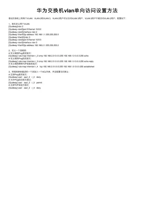
华为三层交换机自反ACL 所有vlan不能访问vlan66 vlan66可以访问所有vlan
- 格式:docx
- 大小:6.57 KB
- 文档页数:1

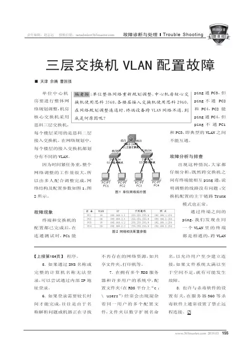
155 2019.03责任编辑:赵志远 投稿信箱:netadmin@故障诊断与处理Trouble Shootingping 通PC3,但ping 不通 PC2和PC4,PC2能ping 通PC4,但ping 不通PC1和PC3,即典型的VLAN 之间不能互通。
故障分析与排查出现这种情况,大家都仔细分析,既然跨交换机之间有终端能相互ping 通,说明调整的线路没有问题;交换机配置的主干链路Trunk模式也正常。
通过终端之间的ping,我们发现在同一个VLAN 里的终端都是相通的,跨VLAN单位中心机房要进行整体网络规划调整,机房核心交换机采用思科三层交换机,每个楼层采用的是思科二层接入交换机。
在网络规划中,每个楼层的接入交换机都划分有不同的VLAN。
因为时间紧任务重,整个网络调整的工作量很大,所以由多人配合调整完成,网络结构及配置参数如图1、图2所示。
故障现象终端和交换机的配置都已完成后,在连通测试时,PC1能三层交换机VLAN 配置故障■ 天津 佘腾 曹国强编者按:单位整体网络重新规划调整,中心机房核心交换机使用思科3560,各楼层接入交换机使用思科2960,在网络规划调整连通时,终端设备跨VLAN 网络不通,到底是何原因呢?图1 单位网络拓扑图图2 网络相关配置参数程序。
5.如果通过DNS 名称或完整的计算机名称无法登录,可以尝试通过内部IP 地址登录。
6.如果登录需要较长时间才能完成,往往是由于名称解析问题或机器正在寻找不再存在的网络资源,如共享文件夹、打印机等。
7.在拥有多个RDS 服务器和许多用户的系统中,配置文件夹(在RDS 平台上“c :\ users”)经常会出现混杂着同一用户的多个配置文件,文件夹以数字扩展名命名,以允许用户至少建立连接,如果文件系统太满以至于空间不足,就有可能发生故障。
8.也许与杀毒软件的设置有关,在服务器360等杀毒软件上通常设置了禁止远程连接。
N【上接第154页】1562019.03 Trouble Shooting 责任编辑:赵志远 投稿信箱:netadmin@故障诊断与处理图3 查看核心三层交换机配置信息图4 查看各端口状态图5 查看VLAN信息之间的终端不通,而且PC 上默认网关都配置正常,这时大家把视线集中在了交换机的配置上。

三层交换机vlan划分和访问控制策略方法一:配置基于端口的VLAN#创建vlan1并进入视图(连接ICG 2000 电信路由器及办公室,信息管理部)<H3C> system-view[H3C] vlan 1#向VLAN1 中加入端口Ethernet1/0/1 和Ethernet1/0/2。
将物理端口1、2划分为VLAN1 [H3C-vlan1] port Ethernet 1/0/1 Ethernet 1/0/2 (或者port e1/0/1 e1/0/2)# 创建VLAN2 并进入其视图<H3c>system-view[H3c] vlan 2#向VLAN2 中加入端口Ethernet1/0/3和Ethernet1/0/5。
[H3C-vlan2] port Ethernet 1/0/3 to Ethernet 1/0/5 (或者port e1/0/3 e1/0/5)# 创建VLAN3 并进入其视图<H3c>system-view[H3C] vlan 3# 向VLAN3 中加入端口Ethernet1/0/6和Ethernet1/0/10[H3C-vlan3] portEthernet 1/0/6 to Ethernet 1/0/10 (或者port e1/0/6 e1/0/10)二:IP 地址配置# 配置VLAN 1 的IP 地址。
<H3C> system-view[H3C] interface Vlan-interface 1[H3C-Vlan-interface1] ip address 192.168.1.1 255.255.255.0# 配置VLAN 2的IP 地址。
<H3C> system-view[H3C] interface Vlan-interface 2[H3C-Vlan-interface2] ip address 192.168.2.1 255.255.255.0# 配置VLAN 3 的IP 地址。

H3C交换机配置ACL禁⽌vlan间互访1、先把基础⼯作做好,就是配置VLAN,配置Trunk,确定10个VLAN和相应的端⼝都正确。
假设10个VLAN的地址分别是192.168.10.X,192.168.20.X。
192.168.100.X,与VLAN号对应。
2、为第⼀个VLAN 10创建⼀个ACL,命令为ACL number 2000这个2000号,可以写的数是2000-2999,是基本的ACL定义。
然后在这个ACL下继续定义rule,例如rule 1 deny source 192.168.20.0rule 2 deny source 192.168.30.0rule 3 deny source 192.168.40.0rule 4 deny source 192.168.50.0rule 5 deny source 192.168.60.0rule 6 deny source 192.168.70.0rule 7 deny source 192.168.80.0rule 8 deny source 192.168.90.0然后进⼊VLAN接⼝interface vlan 10在vlan 10接⼝下,启⽤上⾯定义的规则:packet-filter outbound ip-group 2000这应该就可以了,其它VLAN也按这个⽅法定义。
这⼀句:packet-filter outbound ip-group 2000 设备有可能不⽀持,那你就得换种⽅法定义ACL,使⽤3000-3999之间的扩展ACL定义:rule 1 deny destination 192.168.20.0....然后在vlan接⼝下启⽤packet-filter inbound ip-group 3000。
![H3C配置实例]三层交换机VLAN间限制通讯](https://uimg.taocdn.com/4397d73531126edb6f1a10a3.webp)
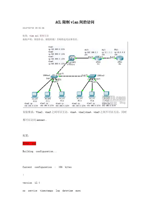
ACL限制vlan间的访问2010-08-03 09:32:06标签:vlan acl限制互访版权声明:原创作品,谢绝转载!否则将追究法律责任。
实验要求:Vlan2、vlan3之间可以互访,vlan4、vlan2,vlan4、vlan3之间不可以互访,同时都可以访问internet 。
配置:R1#sh runBuilding configuration...Current configuration : 456 bytes!version 12.4no service timestamps log datetime msecno service timestamps debug datetime msec no service password-encryption!hostname R1!!interface FastEthernet0/0no ip addressduplex autospeed autoshutdown!interface FastEthernet0/1ip address 12.1.1.2 255.255.255.0duplex autospeed auto!interface Vlan1no ip addressshutdown!ip classless!line con 0line vty 0 4login!!endR0#sh runBuilding configuration...Current configuration : 826 bytes!version 12.4no service timestamps log datetime msec no service timestamps debug datetime msec no service password-encryption!hostname R0!interface FastEthernet0/0ip address 192.168.0.1 255.255.255.0ip nat insideduplex autospeed auto!interface FastEthernet0/1ip address 12.1.1.1 255.255.255.0ip nat outsideduplex autospeed auto!interface Vlan1no ip addressshutdown!ip nat inside source list 1 interface FastEthernet0/1 overload ip classlessip route 192.168.2.0 255.255.255.0 192.168.0.2ip route 192.168.3.0 255.255.255.0 192.168.0.2ip route 192.168.4.0 255.255.255.0 192.168.0.2 ip route 0.0.0.0 0.0.0.0 12.1.1.2!!access-list 1 permit any!!line con 0exec-timeout 0 0logging synchronousline vty 0 4login!!end3750sw1#sh runBuilding configuration...Current configuration : 1969 bytes!version 12.2no service timestamps log datetime msec no service timestamps debug datetime msec no service password-encryption!hostname 3750sw1!ip routing!no ip domain-lookup!!interface FastEthernet0/1![output cut]!interface FastEthernet0/24!interface GigabitEthernet0/1switchport trunk encapsulation dot1qswitchport mode trunk!interface GigabitEthernet0/2!interface Vlan1ip address 192.168.0.2 255.255.255.0 !interface Vlan2ip address 192.168.2.1 255.255.255.0 ip access-group 101 in!interface Vlan3ip address 192.168.3.1 255.255.255.0 ip access-group 102 in!interface Vlan4ip address 192.168.4.1 255.255.255.0 ip access-group 103 in!ip classlessip route 0.0.0.0 0.0.0.0 192.168.0.1 !access-list 101 permit ip 192.168.2.0 0.0.0.255 192.168.3.0 0.0.0.255 access-list 101 deny ip 192.168.2.0 0.0.0.255 192.168.4.0 0.0.0.255 access-list 101 permit ip any anyaccess-list 102 permit ip 192.168.3.0 0.0.0.255 192.168.2.0 0.0.0.255 access-list 102 deny ip 192.168.3.0 0.0.0.255 192.168.4.0 0.0.0.255 access-list 102 permit ip any anyaccess-list 103 deny ip 192.168.4.0 0.0.0.255 192.168.2.0 0.0.0.255 access-list 103 deny ip 192.168.4.0 0.0.0.255 192.168.3.0 0.0.0.255 access-list 103 permit ip any any!!line con 0exec-timeout 0 0logging synchronousline vty 0 4login!!end2960sw2#sh runBuilding configuration...Current configuration : 1134 bytes!version 12.2no service timestamps log datetime msec no service timestamps debug datetime msec no service password-encryption!hostname 2960sw2!!interface FastEthernet0/1switchport access vlan 2!interface FastEthernet0/2switchport access vlan 3interface FastEthernet0/3switchport access vlan 4!interface FastEthernet0/4![output cut]!interface FastEthernet0/24 !interface GigabitEthernet1/1 switchport mode trunk!interface GigabitEthernet1/2 switchport mode trunk!interface Vlan1no ip addressshutdown!!line con 0line vty 0 4loginline vty 5 15login!!end2960sw3#sh runBuilding configuration...Current configuration : 1111 bytes!version 12.2no service timestamps log datetime msec no service timestamps debug datetime msec no service password-encryption!hostname 2960sw3!interface FastEthernet0/1switchport access vlan 2!interface FastEthernet0/2switchport access vlan 3!interface FastEthernet0/3switchport access vlan 4!interface FastEthernet0/4![output cut]!interface FastEthernet0/24 !interface GigabitEthernet1/1 !interface GigabitEthernet1/2 switchport mode trunk!interface Vlan1no ip address shutdown!!line con 0!line vty 0 4 loginline vty 5 15 login!!end验证:由此PC0得vlan2可以访问vlan3和internet,不可以访问vlan4。
华为交换机故障排查案例华为交换机是一种常见的网络设备,用于在计算机网络中传输数据。
然而,由于各种原因,交换机可能会出现故障,导致网络中断或性能下降。
下面列举了一些华为交换机故障排查案例,希望能对读者有所帮助。
1. 网络中断:当网络中断时,首先要检查交换机的电源是否正常,以及是否有任何硬件故障。
如果电源和硬件都正常,则可能是由于配置错误或软件问题导致的。
此时,可以通过查看交换机日志来查找问题,并尝试重新配置交换机。
2. 性能下降:如果网络性能下降,可能是由于交换机的负载过高或网络拓扑不合理导致的。
可以通过查看交换机的流量统计信息来确定是否存在负载过高的情况,并尝试优化网络拓扑以提高性能。
3. VLAN故障:VLAN是一种逻辑分区技术,用于将交换机划分为多个虚拟局域网。
如果VLAN无法正常工作,可能是由于交换机端口配置错误或VLAN故障引起的。
可以通过检查端口配置和VLAN设置来解决问题。
4. STP故障:STP(Spanning Tree Protocol)是一种用于防止网络环路的协议。
如果STP无法正常工作,可能会导致网络中断或性能下降。
可以通过查看交换机的STP配置和状态来确定是否存在STP故障,并尝试重新配置或调整STP参数。
5. 电力故障:如果交换机无法正常供电,可能会导致整个网络中断。
可以通过检查交换机电源和电缆连接来确定是否存在电力故障,并尝试修复或更换故障设备。
6. 网络攻击:如果交换机遭受网络攻击,可能会导致网络中断或性能下降。
可以通过检查交换机的安全配置和日志来确定是否受到攻击,并尝试加强安全措施以防止类似攻击再次发生。
7. 端口故障:如果交换机端口无法正常工作,可能会导致网络中断或性能下降。
可以通过检查端口状态和配置来确定是否存在端口故障,并尝试重新配置或更换故障端口。
8. 路由故障:如果交换机无法正确路由数据包,可能会导致网络中断或性能下降。
可以通过检查交换机的路由表和路由配置来确定是否存在路由故障,并尝试重新配置或调整路由参数。
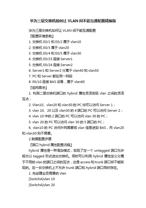
华为三层交换机如何让VLAN间不能互通配置精编版华为三层交换机如何让VLAN间不能互通配置『配置环境参数』1. 交换机E0/1和E0/2属于vlan102. 交换机E0/3属于vlan203. 交换机E0/4和E0/5属于vlan304. 交换机E0/23连接Server15. 交换机E0/24连接Server26. Server1和Server2分属于vlan40和vlan507. PC和Server都在同一网段8. E0/10连接BAS设备,属于vlan60『组网需求』1. 利用二层交换机端口的hybrid属性灵活实现vlan之间的灵活互访;2. Vlan10、vlan20和vlan30的PC均可以访问Server 1;3. vlan 10、20以及vlan30的4端口的PC可以访问Server 2;4. vlan 10中的2端口的PC可以访问vlan 30的PC;5. vlan 20的PC可以访问vlan 30的5端口的PC;6. vlan10的PC访问外网需要将vlan信息送到BAS,而vlan20和vlan30则不需要。
2 数据配置步骤『端口hybrid属性配置流程』hybrid 属性是一种混杂模式,实现了在一个untagged端口允许报文以tagged形式送出交换机。
同时可以利用hybrid属性定义分属于不同的vlan的端口之间的互访,这是access和trunk端口所不能实现的。
在一台交换机上不允许trunk端口和hybrid端口同时存在。
1. 先创建业务需要的vlan[SwitchA]vlan 10[SwitchA]vlan 20[SwitchA]vlan 30[SwitchA]vlan 40[SwitchA]vlan 502. 每个端口,都配置为 hybrid状态[SwitchA]interface Ethernet 0/1[SwitchA-Ethernet0/1]port link-type hybrid3. 设置端口的pvid等于该端口所属的vlan[Switch-Ethernet0/1]port hybrid pvid vlan 104. 将希望可以互通的端口的pvid vlan,设置为untagged vlan,这样从该端口发出的广播帧就可以到达本端口[Switch-Ethernet0/1]port hybrid vlan 10 40 50 60 untagged 实际上,这种配置是通过 hybrid 端口的 pvid 来唯一的表示一个端口,接收端口通过是否将 vlan 设置为 untagged vlan,来控制是否与 pvid vlan 为该 vlan 的端口互通。
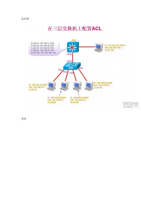
拓扑图要求3750配置:3750#conf t3750(config)#int f0/153750(config-if)#switchport mode trunk3750(config)#end3750#vlan database3750(vlan)#vtp server3750(vlan)#vtp domain sy3750(vlan)#vtp password cisco3750(vlan)#vlan 103750(vlan)#vlan 203750(vlan)#vlan 303750(vlan)#vlan 403750(vlan)#vlan 1003750(vlan)#exit3750(config)#ip routing3750(config)#int vlan 103750(config-if)#ip address 192.168.10.1 255.255.255.0 3750(config-if)#no shutdown3750(config-if)#exit3750(config)#int vlan 203750(config-if)#ip address 192.168.20.1 255.255.255.0 3750(config-if)#no shutdown3750(config-if)#exit3750(config)#int vlan 303750(config-if)#ip address 192.168.30.1 255.255.255.03750(config-if)#no shutdown3750(config-if)#exit3750(config)#int vlan 403750(config-if)#ip address 192.168.40.1 255.255.255.03750(config-if)#no shutdown3750(config-if)#exit3750(config)#int vlan 1003750(config-if)#ip address 192.168.100.1 255.255.255.03750(config-if)#no shutdown3750(config-if)#exit3750(config)#end3750(config)#int f0/13750(config-if)#switchport access vlan 1003750(config-if)#end配置ACL3750#conf t3750(config)#access-list 100 deny ip 192.168.10.0 0.0.0.255 192.168.20.0 0.0.0.255 3750(config)#access-list 100 deny ip 192.168.10.0 0.0.0.255 192.168.30.0 0.0.0.255 3750(config)#access-list 100 permit ip any any3750(config)#access-list 101 deny ip 192.168.20.0 0.0.0.255 192.168.10.0 0.0.0.255 3750(config)#access-list 101 deny ip 192.168.20.0 0.0.0.255 192.168.30.0 0.0.0.255 3750(config)#access-list 101 permit ip any any3750(config)#access-list 102 deny ip 192.168.30.0 0.0.0.255 192.168.10.0 0.0.0.255 3750(config)#access-list 102 deny ip 192.168.30.0 0.0.0.255 192.168.20.0 0.0.0.255 3750(config)#access-list 102 permit ip any any3750(config)#ip access-list extended infilter //在入方向放置reflect//3750(config-ext-nacl)#permit ip any any reflect ccna3750(config-ext-nacl)#exit3750(config)#ip access-list extended outfilter //在出方向放置evaluate//3750(config-ext-nacl)#evaluate ccna3750(config-ext-nacl)#deny ip 192.168.10.0 0.0.0.255 any3750(config-ext-nacl)#deny ip 192.168.20.0 0.0.0.255 any3750(config-ext-nacl)#deny ip 192.168.30.0 0.0.0.255 any3750(config-ext-nacl)#permit ip any any3750(config-ext-nacl)#exit3750(config)#int vlan 40 //应用到管理接口//3750(config-if)#ip access-group infilter in3750(config-if)#ip access-group outfilter out3750(config-if)#exit3750(config)#int vlan 103750(config-if)#ip access-group 100 in3750(config-if)#exit3750(config)#int vlan 203750(config-if)#ip access-group 101 in3750(config-if)#exit3750(config)#int vlan 303750(config-if)#ip access-group 102 in3750(config-if)#end2960配置:2960#conf t2960(config)#int f0/152960(config-if)#switchport mode trunk2960(config-if)#switchport trunk encapsulation dot1q2960(config-if)#end2960#vlan database2960(vlan)#vtp client2960(vlan)#vtp domain sy2960(vlan)#vtp password cisco2960(vlan)#exit2960#show vtp statusVTP Version : 2Configuration Revision : 2Maximum VLANs supported locally : 256Number of existing VLANs : 10VTP Operating Mode : ClientVTP Domain Name : syVTP Pruning Mode : EnabledVTP V2 Mode : DisabledVTP Traps Generation : DisabledMD5 digest : 0x4D 0xA8 0xC9 0x00 0xDC 0x58 0x2F 0xDD Configuration last modified by 0.0.0.0 at 3-1-02 00:13:342960#show vlan-sw briefVLAN Name Status Ports---- -------------------------------- --------- ------------------------------- 1 default active Fa0/0, Fa0/1, Fa0/2, Fa0/3Fa0/4, Fa0/5, Fa0/6, Fa0/7Fa0/8, Fa0/9, Fa0/10, Fa0/11Fa0/12, Fa0/13, Fa0/1410 VLAN0010 active20 VLAN0020 active30 VLAN0030 active40 VLAN0040 active100 VLAN0100 active1002 fddi-default active1003 token-ring-default active1004 fddinet-default active1005 trnet-default active2960#conf t2960(config)#int f0/12960(config-if)#switchport access vlan 102960(config-if)#int f0/22960(config-if)#switchport access vlan 202960(config-if)#int f0/32960(config-if)#switchport access vlan 302960(config-if)#int f0/42960(config-if)#switchport access vlan 402960(config-if)#end客户机验证:PC1:PC1#ping 192.168.20.20Type escape sequence to abort.Sending 5, 100-byte ICMP Echos to 192.168.20.20, timeout is 2 seconds: U.U.USuccess rate is 0 percent (0/5)PC1#ping 192.168.30.30Type escape sequence to abort.Sending 5, 100-byte ICMP Echos to 192.168.30.30, timeout is 2 seconds: U.U.USuccess rate is 0 percent (0/5)PC1#ping 192.168.40.40Type escape sequence to abort.Sending 5, 100-byte ICMP Echos to 192.168.40.40, timeout is 2 seconds: U.U.USuccess rate is 0 percent (0/5)PC1#ping 192.168.100.100Type escape sequence to abort.Sending 5, 100-byte ICMP Echos to 192.168.100.100, timeout is 2 seconds: !!!!!Success rate is 100 percent (5/5), round-trip min/avg/max = 104/268/336 msPC2#ping 192.168.10.10Type escape sequence to abort.Sending 5, 100-byte ICMP Echos to 192.168.10.10, timeout is 2 seconds: U.U.USuccess rate is 0 percent (0/5)PC2#ping 192.168.30.30Type escape sequence to abort.Sending 5, 100-byte ICMP Echos to 192.168.30.30, timeout is 2 seconds: U.U.USuccess rate is 0 percent (0/5)PC2#ping 192.168.40.40Type escape sequence to abort.Sending 5, 100-byte ICMP Echos to 192.168.40.40, timeout is 2 seconds: U.U.USuccess rate is 0 percent (0/5)PC2#ping 192.168.100.100Type escape sequence to abort.Sending 5, 100-byte ICMP Echos to 192.168.100.100, timeout is 2 seconds: !!!!!Success rate is 100 percent (5/5), round-trip min/avg/max = 56/170/336 msPC3:PC3#ping 192.168.10.10Type escape sequence to abort.Sending 5, 100-byte ICMP Echos to 192.168.10.10, timeout is 2 seconds:.U.U.Success rate is 0 percent (0/5)PC3#ping 192.168.20.20Type escape sequence to abort.Sending 5, 100-byte ICMP Echos to 192.168.20.20, timeout is 2 seconds: U.U.USuccess rate is 0 percent (0/5)PC3#ping 192.168.40.40Type escape sequence to abort.Sending 5, 100-byte ICMP Echos to 192.168.40.40, timeout is 2 seconds: U.U.USuccess rate is 0 percent (0/5)PC3#ping 192.168.100.100Type escape sequence to abort.Sending 5, 100-byte ICMP Echos to 192.168.100.100, timeout is 2 seconds: !!!!!Success rate is 100 percent (5/5), round-trip min/avg/max = 144/218/416 msPC4#ping 192.168.10.10Type escape sequence to abort.Sending 5, 100-byte ICMP Echos to 192.168.10.10, timeout is 2 seconds:.!!!!Success rate is 80 percent (4/5), round-trip min/avg/max = 240/331/508 ms PC4#ping 192.168.20.20Type escape sequence to abort.Sending 5, 100-byte ICMP Echos to 192.168.20.20, timeout is 2 seconds:!!!!!Success rate is 100 percent (5/5), round-trip min/avg/max = 220/288/356 ms PC4#ping 192.168.30.30Type escape sequence to abort.Sending 5, 100-byte ICMP Echos to 192.168.30.30, timeout is 2 seconds:!!!!!Success rate is 100 percent (5/5), round-trip min/avg/max = 144/207/268 ms PC4#ping 192.168.100.100Type escape sequence to abort.Sending 5, 100-byte ICMP Echos to 192.168.100.100, timeout is 2 seconds: !!!!!Success rate is 100 percent (5/5), round-trip min/avg/max = 96/219/440 msPC5:PC5#ping 192.168.10.10Type escape sequence to abort.Sending 5, 100-byte ICMP Echos to 192.168.10.10, timeout is 2 seconds:!!!!!Success rate is 100 percent (5/5), round-trip min/avg/max = 92/194/284 ms PC5#ping 192.168.20.20Type escape sequence to abort.Sending 5, 100-byte ICMP Echos to 192.168.20.20, timeout is 2 seconds:!!!!!Success rate is 100 percent (5/5), round-trip min/avg/max = 144/209/336 ms PC5#ping 192.168.30.30Type escape sequence to abort.Sending 5, 100-byte ICMP Echos to 192.168.30.30, timeout is 2 seconds:!!!!!Success rate is 100 percent (5/5), round-trip min/avg/max = 64/184/372 ms PC5#ping 192.168.40.40Type escape sequence to abort.Sending 5, 100-byte ICMP Echos to 192.168.40.40, timeout is 2 seconds:!!!!!Success rate is 100 percent (5/5), round-trip min/avg/max = 192/239/308 ms。
三层交换机配置ACL(访问节制列表)之袁州冬雪创作说明:书本上讲述的ACL主要是应用在路由器上,但现在三层交换机在大中型企业中的应用越来越广泛,三层交换机因拥有路由器的功能而逐渐代替路由器.ACL访问节制列表是构建平安规范的网络不成缺少的,但在三层交换机上配置ACL却不为一些刚进企业的初级网络管理维护人员所知.在这里我先容一下在三层交换机上配置ACL的试验过程.试验拓扑先容:三层交换机上配置当地Vlan 实现下层接入层交换机分歧Vlan互通.F0/1 192.168.70.2 (开启路由功能)路由器上配置FF0/1 192.168.70.1试验步调:1、在二层交换机上把相应的PC加入VLAN检查交换机Switch0Switch0(config)#show run!interface FastEthernet0/1switchport access vlan 2!interface FastEthernet0/2switchport access vlan 3!检查交换机Switch1Switch1#show run!interface FastEthernet0/3switchport access vlan 4!interface FastEthernet0/4switchport access vlan 5!2、在三层交换机上配置相应的当地VALNSwitch(config)#inter vl 2Switch(config-if)#no shutSwitch(config)#inter vl 3Switch(config-if)#no shutSwitch(config)#inter vl 4Switch(config-if)#no shutSwitch(config)#inter vl 5Switch(config-if)#no shutSwitch(config-if)#exi在接口itnerface f0/1上开启路由接口Switch(config)#inter f0/1Switch(config-if)#no switchport3、在二层交换机和三层交换机之间开启中继链路4、在路由器和三层交换机上配置动态路由协议RIP Router(config)#router ripRouter(config)#Router(config)#三层交换机上配置Switch(config)#router ripSwitch(config-router)#neSwitch(config-router)#5、验证各PC互通Pinging 192.168.30.20 with 32 bytes of data: Request timed out.Reply from 192.168.30.20: bytes=32 time=110ms TTL=126Reply from 192.168.30.20: bytes=32 time=110msTTL=126Reply from 192.168.30.20: bytes=32 time=125msTTL=126Ping statistics for 192.168.30.20:Packets: Sent = 4, Received = 3, Lost = 1 (25% loss),Approximate round trip times in milli-seconds:Minimum = 110ms, Maximum = 125ms, Average = 115msPinging 192.168.40.30 with 32 bytes of data:Reply from 192.168.40.30: bytes=32 time=94msTTL=126Reply from 192.168.40.30: bytes=32 time=125msTTL=126Reply from 192.168.40.30: bytes=32 time=125msTTL=126Reply from 192.168.40.30: bytes=32 time=109msTTL=126Ping statistics for 192.168.40.30:Packets: Sent = 4, Received = 4, Lost = 0 (0% loss),Approximate round trip times in milli-seconds: Minimum = 94ms, Maximum = 125ms, Average = 113ms 6、在三层交换机上配置ACL注意如果设置分歧VALN的PC之间不克不及互通,则应用的接口应为VLAN对应的当地Llan接口.设置PC1不克不及ping通PC3和PC4应用于接口Switch(config)#inter vl 4Switch(config-if)#ip access-group 10 outSwitch(config-if)#exiSwitch(config)#inter vl 5Switch(config-if)#ip access-group 10 outSwitch(config-if)#或者是Switch(config)#inter vl 2Switch(config-if)#ip access-group 10 inSwitch(config-if)#(注上:此处ACL应用于接口,从PC1到PC3 和PC4,数据流走向是颠末三层交换机上配置的当地Vlan2接口进入,再从三层交换机上配置的当地Vlan4出去到达PC3,从当地Vlan5出去到达PC4.所以在配置ACL时应注意访问节制列表应用于哪儿接口?!)7、验证:PC1不克不及ping通PC3和PC4Pinging 192.168.50.40 with 32 bytes of data: Request timed out.Request timed out.Ping statistics for 192.168.50.40:Packets: Sent = 3, Received = 0, Lost = 3 (100% loss),Control-C^CPinging 192.168.40.30 with 32 bytes of data: Request timed out.Request timed out.Request timed out.Request timed out.容易发生的错误分析:能够在学习的时候只是学习了如何在路由器上配置ACL,而不知道在三层交换机上也能配置ACL.或许有些同学在三层交换机上各接口开启路由接口形式,就把三层交换机当作路由器来配置,虽说三层交换机有路由器的功能,但是一些协议运用起来还是和路由器有差此外.就比方说这个试验在三层交换机的下毗连口f0/5和f0/6上开启路由接口形式,成果是不配置ACL的前提下,各Vlan欠亨.所以f0/5和f0/6不克不及开启路由接口形式.在Vlan 2、3、4、5之间配置ACL时,要弄清楚数据流的进、出接口,在这里Vlan2、3、4、5之间的数据流的进、出口就是在三层交换机上配置当地Vlan接口.其实ACL原理都一样、只要清楚三层交换机上配置ACL和路由器上配置的区别,在三层交换机上配置ACL就简单易行.。