上海英展BH(3)使用技术说明书
- 格式:pdf
- 大小:866.44 KB
- 文档页数:32

上海英展机电企业有限公司使用说明书目录注意事项 (2)使用前之准备工作 (2)第一章 产品介绍 (3)第一节 简介 (3)第二节 单位转换关系 (3)第二章 显示部分说明 (4)第三章 电源说明 (5)第一节 电源选择 (5)第二节 充电电压 (5)第三节 耗电流 (5)第四节 低电源警示 (6)第五节 内存电源(此为含打印机机种) (6)第四章 按键说明 (7)第五章 功能操作说明 (8)第一节 背光功能 (8)第二节 计重功能 (8)第三节 计数功能 (14)第四节 错误讯息 (14)第六章 功能设定模式 (15)F4 ⇒ 设定检校功能 (16)F5 ⇒ 设定RS-232接口(选配)及微型打印机输出 (17)F6 ⇒ 跳出设定模式 (25)F8 ⇒ 设定重量暂留(hold)模式 (26)F10 ⇒ G值校正 (28)第七章 Load Cell输入信号接脚说明 (29)第八章 选配功能说明 (30)附录一 七节码字样说明 (31)附录二 打印机相关组装 (32)附录三 FB630吊钩组装方式 (33)附录四 按键对照表 (34)三包事项 (35)产品保证卡 (36)注意事项一、严禁淋雨或以水冲洗。
如不慎沾水,请用干布擦拭干净。
二、本产品不正常时,请尽速送到经销商处,我们将竭诚为您服务。
三、严禁将本产品置于高温或潮湿之场所。
四、勿让蟑螂侵入及小生物寄生机内。
五、严禁撞击,重压(勿超过其最大秤量)。
六、本产品若长期不使用,请取出干电池,将本产品擦拭干净,放入干燥剂后以塑料袋包好。
七、本产品使用时,秤物之重心须位于秤盘之中心点,且秤物不超出秤盘范围,以确保其准确度。
八、本产品所附插座符合国家标准的有关规定,不能使用非标产品。
九、本产品上的铅封请勿打开。
如擅自开启,所产生的后果由用户自负。
十、如对本产品有任何建议,请不吝指正之。
十一、本说明书内容与实际产品不符之处,本公司有保留修改的权利。

英展實業股份有限公司EXCELL PRECISION CO., LTD.電 子 天 平 使 用 說 明 書 ©英展實業股份有限公司目錄注意事項 (3)使用前之準備工作 (3)第一章顯示部份說明 (4)第二章功能操作說明 (5)2-1 計重模式 (5)2-2 計數模式 (6)2-3 百分比模式 (6)第三章防風罩組裝圖 (7)第四章外觀尺寸圖 (8)第五章功能設定操作說明 (9)5-1 一般功能設定 (10)5-1-1 選擇開機單位 (11)5-1-2 選擇使用單位 (12)5-1-3 選擇自動關機時間 (13)5-1-4 選擇背光模式 (14)5-1-5 選擇計數模式下是否自動單重校正 (15)5-2 重量外部校正及G值外部校正 (16)5-2-1 重量外部校正 (17)5-2-2 G值外部校正 (18)5-2-3 回復出廠設定值 (19)5-3 RS232設定 (20)5-3-1 RS232傳送方式設定 (20)5-3-2 RS232鮑率設定 (22)5-3-3 RS232通訊協定設定 (23)5-3-4 RS232輸出格式設定 (24)5-3-5 回零範圍設定 (25)5-3-6 重量變化範圍設定 (26)5-3-7 顯示日期時間(選配) (27)5-3-8 時間日期設定(選配) (27)第六章 電源部份說明 (28)電源選擇 (29)耗電流 (29)錯誤訊息 (29)附錄一 RS232 雙向格式 (30)RS232 輸出格式 (31)附錄二單位轉換表 (35)附錄三規格表 (36)附錄四七節碼字樣說明 (38)專利名稱:電子秤專利號:新式樣 D 111525感謝愛用者選購英展高精度電子秤為有效幫助您正確的使用本公司產品,請細讀使用說明,將有助益於操作及延長產品之壽命,並可減少故障機會。
注意事項1. 嚴禁淋雨或以水沖洗。
(如不慎沾水,請用乾布擦拭乾淨,機器不正常時,請儘速送到經銷商處,我們將竭誠為您服務。

BH-3M铣床数控系统使用说明书(2013版)武汉保华数控工作室2目次第一章系统的启动与操作 (7)1.1系统初始化 (7)1.1.1首次通电初始化 (7)1.1.2正常开机初始化 (7)1.1.3特殊情况下的初始化处理 (7)1.2操作与面板组成 (8)1.2.1显示部分 (8)1.2.2开关部分 (8)1.2.2.1 电源开关 (9)1.2.2.2 驱动开关 (9)1.2.3键盘部分 (9)1.2.3.1 退出键 (9)1.2.3.2 空格键 (9)1.2.3.3 删除键 (9)1.2.3.4 回车键 (9)1.2.3.5 上档键 (9)1.2.3.6 增速键 (9)1.2.3.7 减速键 (9)1.2.3.8 暂停键 (10)1.2.3.9 返回键 (10)1.2.3.10 方向键 (10)1.2.3.11 换刀键 (10)1.2.3.12 冷却液控制键 (10)1.2.3.13 主轴控制键 (10)1.3系统的启动 (11)第二章自动运行 (12)2.1连续运行 (13)2.2单步运行 (13)2.3跳步运行 (13)2.4调试运行 (13)2.5加工过程中的屏幕显示图例 (13)第三章手动方式 (14)3.1点动进给 (14)3.2连续进给 (14)3.3手动换刀 (14)3.4手动调速 (14)3.5手动返回工件坐标参考点 (15)3.6启动/停止主轴和冷却泵 (15)3.7立即执行数控命令 (15)第四章设置系统参数 (16)4.1刀具补偿 (16)4.2间隙补偿 (16)4.3G00快进速度 (16)第五章编辑加工程序 (17)5.1工件程序的名称 (17)5.2工件加工程序的输入 (17)5.3程序的修改 (17)5.4电子盘与程序管理 (18)5.4.1电子盘 (18)5.4.2程序文件管理命令 (18)5.4.2.1 自动行号命令(AUTO) (18)5.4.2.2 重编行号命令(REN)(暂无) (18)5.4.2.3 调入命令(LOAD) (19)5.4.2.4 存贮命令(SA VE) (19)5.4.2.5 删除程序命令(DEL) (19)5.4.2.6 更名命令(RENAME) (19)5.4.2.7 电子盘拷贝命令(COPY) (19)5.4.2.8 加锁命令(LOCK) (19)5.4.2.9 开锁命令(UNLOCK) (19)5.4.2.10 显示目录(DIR) (19)5.4.2.11 格式化命令(INIT) (20)5.4.2.12 列表命令(LIST) (20)5.4.2.13 清除内存命令(NEW) (20)5.4.2.14 清除屏幕命令(CLS) (20)5.5计算器 (20)第六章数控语言及命令 (22)6.1坐标系统和程序结构 (22)6.1.1坐标系统 (22)6.1.1.1 工件坐标系 (22)6.1.1.2 加工起始点 (22)6.1.1.3 机械参考点 (22)6.1.2程序及格式 (22)6.1.2.1 工件程序 (22)6.1.2.2 行号 (22)6.1.2.3 指令字 (23)6.1.2.4 程序的执行顺序 (23)6.2编程指令 (23)6.2.1术语解释 (23)6.2.1.1 模态 (23)6.2.1.2 绝对坐标 (24)6.2.1.3 增量坐标 (24)6.2.2准备功能(G功能) (24)6.2.2.1 快速点定位(G00) (24)6.2.2.2 直线插补指令G01 (24)6.2.2.3 圆弧插补指令G02、G03 (24)6.2.2.4 螺旋线插补指令 (25)6.2.2.5 正弦曲线加工 (26)6.2.2.6 程序延时指令G04 (26)6.2.2.7 返回工件坐标参考点指令G26、G27、G29 (26)6.2.2.8 程序循环指令G22、G80 (26)26.2.2.9 钻孔循环程序举例 (27)6.2.2.10 图形窗口命令G66 (28)6.2.2.11 坐标设置指令G92 (28)6.2.3辅助功能(M功能) (29)6.2.3.1 程序暂停指令M00 (29)6.2.3.2 程序结束指令M02 (29)6.2.3.3 主轴正转指令M03 (29)6.2.3.4 主轴反转指令M04 (29)6.2.3.5 主轴停止指令M05 (29)6.2.3.6 开冷却泵指令M08 (29)6.2.3.7 关冷却泵指令M09 (29)6.2.3.8 自定义指令M41、M42、M43、M44 (29)6.2.3.9 程序跳转指令M97 (29)6.2.3.10 子程序调用指令M98和子程序返回指令M99 (30)6.2.4进给功能(F) (30)6.2.5主轴功能(S) (31)6.2.5.1 开关量主轴速度控制指令 (31)6.2.5.2 模拟量主轴速度控制指令 (31)6.2.5.3 指令使用举例 (31)6.2.6刀具功能(T) (32)6.2.6.1 换刀与刀具长度补偿 (32)6.2.6.2 刀具半径补偿 (32)6.2.7设置/返回机械参考点 (37)6.2.7.1 G74设置机械参考点指令: (37)6.2.7.2 G30返回机械参考点指令: (37)6.2.7.3 机械参考点信号接线 (37)6.2.7.4 返回机械参考点的执行过程 (37)6.2.7.5 机械参考点原理及设置步骤 (37)6.2.8数控BASIC命令 (38)6.2.8.1 变量、函数和数学表达式 (38)6.2.8.2 数学表达式及其运算规则 (39)6.2.8.3 逻辑运算 (39)6.2.8.4 BASIC命令 (39)6.3编程举例 (41)6.4程序执行中的错误分析 (42)第七章通讯功能介绍 (43)7.1串行通讯 (43)7.1.1通讯协议 (43)7.1.2通讯电缆的接线方式: (43)7.1.3注意事项: (43)7.1.4安装和设置通讯软件 (43)7.2文件传输 (44)7.2.1把CNC中的工件加工程序传送到PC (44)7.2.2把PC上的工件加工程序传送到CNC (45)7.3DNC方式 (45)7.3.1 NC程序的格式及要求 (45)7.3.2 DNC数控加工的操作 (46)7.3.2.1 按7.1.2节的要求连接电缆。
三氟化硼阀门的使用说明书第一章:引言1.1 产品概述三氟化硼阀门是一种用于控制流体流动的设备,广泛应用于化工、石油、制药等行业。
本使用说明书旨在帮助用户正确安装、操作和维护三氟化硼阀门,确保其正常运行和延长使用寿命。
1.2 安全须知在使用三氟化硼阀门之前,请务必仔细阅读本章节内容,以确保您的安全和设备的正常运行。
1) 在操作阀门之前,确保阀门处于关闭状态,并切断供应介质的压力。
2) 使用阀门时,请佩戴适当的防护装备,如手套、护目镜等。
3) 阀门的安装和维护应由专业人员进行,确保操作正确和安全。
4) 阀门的维护和保养应定期进行,以确保其正常运行。
第二章:产品特点2.1 结构特点三氟化硼阀门采用优质的三氟化硼材料制造,具有耐腐蚀、耐高温、耐磨损等特点。
阀门结构简单紧凑,操作灵活方便。
2.2 技术参数- 额定压力:根据不同型号和规格,额定压力范围为0.6MPa至4.0MPa。
- 适用介质:适用于酸、碱、盐等腐蚀性介质。
- 适用温度:适用于-50℃至200℃的温度范围。
第三章:安装与操作3.1 安装步骤1) 在安装前,检查阀门是否完好无损。
2) 根据管道连接方式,选择合适的连接方式(法兰连接、螺纹连接等)。
3) 在安装过程中,确保阀门处于关闭状态,避免介质泄漏。
3.2 操作指南1) 打开阀门:顺时针旋转手柄或操作杆,使阀门打开。
2) 关闭阀门:逆时针旋转手柄或操作杆,使阀门关闭。
3) 调节阀门:根据需要,适当旋转手柄或操作杆,调节阀门的开度。
第四章:维护与保养4.1 定期检查定期检查阀门的密封性能、操作灵活性和外观状况,如发现异常情况,应及时进行维修或更换。
4.2 清洁保养定期清洁阀门表面和内部,确保阀门的正常运行。
使用中发现阀门有异物或堵塞时,应及时清理。
第五章:故障排除5.1 常见故障1) 泄漏:检查阀门密封面是否损坏,如有损坏应及时更换密封件。
2) 卡阻:检查阀门内部是否有异物或堵塞,如有应进行清理。

3” BUTTERFLY VALVEMAINTENANCE MANUAL //MM008 REV01 - 27.08.13IMPORTANT:PLEASE READ THE INSTRUCTIONS IN FULL PRIOR TO COMMENCING WORK ON THE VALVE. Manual Contents∙Valve Identification.∙General Assembly Dismantling.∙Valve Dismantling.∙Valve Re-assembly.∙General Assembly Re-assembly.Tooling Required∙13mm A/F Spanner.∙ 2 x 17mm A/F Spanner.∙ 2 x 19mm A/F Spanner.∙ 2 x 24mm A/F Spanner.∙3mm A/F Allen Key.∙6mm A/F Allen Key.∙Torque Wrench.∙Soft Mallet.∙Nut Retainer.∙Small Sharp Knife.∙‘O’ Ring Expanders and Resizers.∙Stuffing Plate Tube.BEFORE ATTEMPTING DISASSEMBLY OR REMOVAL OF ANY FORT VALE COMPONENT, ALWAYS DEPRESSURIZE AND DRAIN ANY PIPING SYSTEMS.Prior to commencing any remedial work :Prior to handling the valve,ascertain the last product carried and ensure that the valve has been correctly decontaminated. Obtain a Material Safety Data Sheet for the last product carried and observe all the Health and Safety advice, particularly with regards to P .P .E. (Personal Protection Equipment)personnel Servicing of valves should be conducted by a “Qualified Person”The term “qualified person” relates to a person familiar with the installation, assembly, operation, applications andlimitations of the component. The person should have the qualifications corresponding to their responsibilities, such as instruction and awareness to comply with all operational, regional and in-company regulations and requirements.Limitations of use/Mis-usePlease observe the maximum allowable working pressure and the minimum/maximum allowable temperature range and ensure that the valve is not operated outside these limitations. Use/operation outside these limits is at the risk of the user and Fort Vale shall bear no responsibility for such actions.ServicingFort Vale components are manufactured for longevity under normal and compatible working conditions. It is the responsibility of the user to take into account the working conditions of the valve and to implement a regular serviceschedule based upon individual circumstances. In addition, a thorough visual inspection of the valve should be made at regular intervals to check for correct operation and signs of corrosion. It must be noted that working at extremes of temperature and/or pressure will reduce the operational life of the valve between services.AFTER ANY REMEDIAL WORK, ENSURE THAT THE VALVE IS LEAK TESTED PRIOR TO RETURNING TO SERVICE.During service or testing, if any problem arises that cannot be resolved with the use of this Maintenance Manual, please contact Fort Vale for further advice and assistance.Risk assessment and hazard assessmentFort Vale recommends a full and comprehensive risk and hazard assessment in accordance with national or locallegislation prior to servicing a valve. Not all service environments are the same and basic instructions may need to be incorporated into the safe procedures for use of the end user. See examples below:- Correct use of personal protection equipment when working with compressed gases- Correct use of personal protection equipment when working with low temperature components- Correct use of personal protection equipment when working with heavy components and the use of lifting equipment - Training and competence ofconducting pressure testingThis page is intentionally blank.A .B Series 3” Butterfly Valve (Clamped and Composite).B. A Series 3” Butterfly Valve (Clamped, Flanged and Composite).C. Original 3” Butterfly Valve (Clamped, Flanged and Composite).Butterfly ValveValve Identification.THIS DRAWING IS AN UNCONTROLLED COPY AND AS SUCH WILL NOT BE AUTOMATICALLY UPDATED Printed by Gerard_van_der_bok on 08 June 2017 at 09:55:32 GMT EXPIRES ON 08 July 2017A . 3” Clamped Butterfly Valves/Footvalve Assemblies. B. 3” Flanges Butterfly Valves/Footvalve Assemblies. C. 3” Composite Butterfly Valves/Footvalve Assemblies.Butterfly ValveGeneral Assembly Breakdown.THIS DRAWING IS AN UNCONTROLLED COPY AND AS SUCH WILL NOT BE AUTOMATICALLY UPDATED Printed by Gerard_van_der_bok on 08 June 2017 at 09:55:32 GMT EXPIRES ON 08 July 2017A. Basic Butterfly Valve Design.B. Valve DismantlingButterfly Valve Valve Dismantling.THIS DRAWING IS AN UNCONTROLLED COPY AND AS SUCH WILL NOT BE AUTOMATICALLY UPDATED Printed by Gerard_van_der_bok on 08 June 2017 at 09:55:32 GMT EXPIRES ON 08 July 2017A. Important Surfaces.B. Spindle Seals.C. Valve Re-assembly.D. Replacing Main Seal and Aligning Closure Plate.E. Pre A Series TIR.Butterfly ValveValve Re-assembly.THIS DRAWING IS AN UNCONTROLLED COPY AND AS SUCH WILL NOT BE AUTOMATICALLY UPDATED Printed by Gerard_van_der_bok on 08 June 2017 at 09:55:32 GMT EXPIRES ON 08 July 2017A. 3” B Series Clamped Butterfly Valves/Footvalves Assemblies.B. 3” A Series and Original Clamped Butterfly Valves/Footvalves Assemblies.C. 3” Flanged Butterfly Valves/Footvalves and Top Discharge Assemblies.D. 3” Composite Butterfly Valves/Footvalves Assemblies.Butterfly ValveGeneral Assembly Re-assembly.THIS DRAWING IS AN UNCONTROLLED COPY AND AS SUCH WILL NOT BE AUTOMATICALLY UPDATED Printed by Gerard_van_der_bok on 08 June 2017 at 09:55:32 GMT EXPIRES ON 08 July 2017This page is intentionally blank.All goods supplied will be subject to Fort Vale Engineering Ltd Terms and Conditions of Sale (Ref. FV4) which are available upon request, or may be viewed at .Please note that this brochure and the contents herein remain the property of Fort Vale Engineering Limited.This brochure may not be copied or reproduced, or the information contained herein divulged to any third party without the prior written permission of Fort Vale Engineering Limited.Repair/refurbishment/resetting of Fort Vale valves may be carried out only by trained and authorised personnel. Fort Vale Engineering Limited shall not, in any circumstances, be liable for injuries, losses, expenses or damage, direct or consequential, sustained by the buyer or any person which may in any degree be attributable to the adoption, either by the buyer or any third party, of technical or other information, data or advice given on behalf of Fort Vale Engineering Limited or however otherwise caused in relation to the use of its products in accordance with Fort Vale Engineering Limited’s recommendation.The specifications included in this catalogue are intended to be generic and must be interpreted as equivalent or functionally equivalent. The identification of many items is facilitated by illustrations (photographs and line drawings). The mention of, or reference to specific companies, national standards, or trade names, including those that might appear on the photographs, is intended for illustration purposes only. It does not imply an endorsement, preference or availability of any specific standard, brand or supplier.The data and information contained herein is being provided for information only and without responsibility, and Fort Vale Engineering Limited makes no representations or warranties, either expressed or implied, as to the accuracy,。

FEATURES / BENEFITS■ H igh Efficient Motor With Upper & LowerBall Bearings / Runs Cooler & Last Longer■ Vortex Impeller / Helps Prevent Clogging ■ S ealed Entry-Replaceable Power Cord / Sealed Entry-Replaceable Power Cord /Easy To Replace In The Field, PreventsWater From Entering The Motor Housing Through A Cut Power Cord (Up To 50’ Available)■ P iggy-Back Switch Design / DefectiveSwitches Can Be Diagnosed By Phone; Pump Can Be Operated Manually By Overriding The Switch■ E very Pump Is Tested In Water /Ensures That The Pump Meets Head & Flow RequirementsAPPLICATIONS■ B asements, Dewatering, Septic Systems,Decorative Ponds1520250510T o t a l H e a d i n F T3050402010Gallons Per MinuteCPS3A –11CPS3V–11Distributed by:wwDISCHARGE1-1/2” NPT. Vertical LIQUID TEMPERATURE 140 Degrees F. (Intermittent)MOTOR HOUSING Cast Iron VOLUTE Cast Iron SEAL PLATE Cast IronIMPELLER Nylon + 30% Fiberglass SHAFT Nickel Plated SteelSHAFT SEALMechanicalCarbon - Rotating Face Ceramic - Stationary Face Buna-N - Elastomer300 Series Stainless Steel - Hardware BEARING (UPPER & LOWER) Single Row, Ball, Oil Lubricated HARDWARE 300 Series Stainless Steel SQUARE RINGS Buna-NCORD (UL / CUL) Listed 16 AWG, Type SJTW10’ Length Standard. Other Lengths Available.CORD ENTRYCompression Grommet - Outer Jacket Seal Quick Disconnect Pin TerminalsMOTOR (SINGLE PHASE)1/3 HP , 1750 RPM, 60HzNEMA L Includes Overload Protection In The Motor.Oil Filled, Class BPermanent Split Capacitor WEIGHT24 lbs (Manual)Model HP Volts Phase Amps Cord Length Switch CPS3-111/31151 4.010Manual CPS3-121/31151 4.020Manual CPS3-131/31151 4.030Manual CPS3-151/31151 4.050Manual CPS3A-111/31151 4.010Float CPS3A-121/31151 4.020Float CPS3A-131/31151 4.030Float CPS3V-111/31151 4.010Vertical Float CPS3V-121/311514.020Vertical FloatChampion Pump Company, Inc • P .O. Box 528• Ashland, OH 44805phone 419-281-4500• toll free 800-659-4491• fax 419-616-1100。
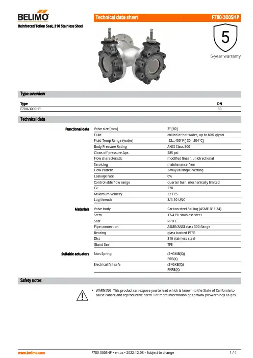
F780-300SHP•Reinforced Teflon Seat, 316 Stainless SteelType overviewType DNF780-300SHP80 Technical dataFunctional data Valve size [mm]3" [80]Fluid chilled or hot water, up to 60% glycolFluid Temp Range (water)-22...400°F [-30...204°C]Body Pressure Rating ANSI Class 300Close-off pressure ∆ps285 psiFlow characteristic modified linear, unidirectionalServicing maintenance-freeFlow Pattern3-way Mixing/DivertingLeakage rate0%Controllable flow range quarter turn, mechanically limitedCv228Maximum Velocity32 FPSLug threads3/4-10 UNCMaterials Valve body Carbon steel full lug (ASME B16.34)Stem17-4 PH stainless steelSeat RPTFEPipe connection ASME/ANSI class 300 flangeBearing glass backed PTFEDisc316 stainless steelGland Seal TFESuitable actuators Non-Spring(2*GMB(X))PRB(X)Electrical fail-safe(2*GKB(X))PKRB(X)Safety notesWARNING: This product can expose you to lead which is known to the State of California tocause cancer and reproductive harm. For more information go to F780-300SHP Product featuresFlow/Mounting detailsDimensionsType DN WeightF780-300SHP8086 lb [39 kg]A B C D E F Number of Bolt Holes16.0" [406]11.7" [298]16.3" [415]12.5" [318]7.9" [201]6.0" [152]8A B C D E F Number of Bolt Holes21.5" [547]11.7" [298]18.3" [464]14.5" [368]7.9" [201]6.0" [152]8A B C D E F Number of Bolt Holes16.8" [426]11.7" [298]16.3" [415]12.5" [318]7.9" [201]6.0" [152]8A B C D E F Number of Bolt Holes16.8" [426]11.7" [298]21.3" [540]17.5" [445]7.9" [201]6.0" [152]8PRXUP-MFT-TModulating, Non Fail-Safe, 24...240 V, NEMA4X with BACnetTechnical dataElectrical dataNominal voltageAC 24...240 V / DC 24...125 V Nominal voltage frequency 50/60 HzNominal voltage rangeAC 19.2...264 V / DC 19.2...137.5 V Power consumption in operation 20 W Power consumption in rest position 6 WTransformer sizing with 24 V 20 VA / with 240 V 52 VAAuxiliary switch2 x SPDT, 1 mA...3 A (0.5 A inductive), DC 5 V...AC 250 V (II, reinforced insulation), 1 x 10° / 1 x 0...90° (default setting 85°)Switching capacity auxiliary switch 1 mA...3 A (0.5 A inductive), DC 5 V...AC 250 V (II, reinforced insulation)Electrical Connection Terminal blocks, (PE) Ground-Screw Overload Protectionelectronic thoughout 0...90° rotation Data bus communicationCommunicative controlBACnet MS/TP Modbus RTU MP-Bus Functional data Torque motor 160 Nm Operating range Y 2...10 V Operating range Y note 4...20 mAInput Impedance100 kΩ for 2...10 V (0.1 mA), 500 Ω for 4...20 mA, 1500 Ω for On/Off Operating range Y variable Start point 0.5...30 V End point 2.5...32 VOperating modes optional variable (VDC, on/off, floating point)Position feedback U 2...10 V Position feedback U note Max. 0.5 mA Position feedback U variable VDC variable Direction of motion motor reversible with app Manual override 7 mm hex crank, supplied Angle of rotation 90°Running Time (Motor)35 s / 90°Running time motor variable 30...120 s Noise level, motor 68 dB(A)Position indicationintegral pointer Safety data Power source ULClass 2 Supply Degree of protection IEC/EN IP66/67Degree of protection NEMA/UL NEMA 4XEnclosureUL Enclosure Type 4XPRXUP-MFT-TApplicationOperationSafety dataAgency ListingcULus acc. to UL60730-1A/-2-14, CAN/CSA E60730-1:02, CE acc. to 2014/30/EU and 2014/35/EU Quality Standard ISO 9001Ambient humidity Max. 100% RH Ambient temperature -22...122°F [-30...50°C]Storage temperature -40...176°F [-40...80°C]Servicingmaintenance-free Weight Weight13 lb [5.9 kg]MaterialsHousing material Die cast aluminium and plastic casingProduct featuresPR Series valve actuators are designed with an integrated linkage and visual position indicators. For outdoor applications, the installed valve must be mounted with the actuator at or above horizontal. For indoor applications the actuator can be in any location including directly under the valve.The PR series actuator provides 90° of rotation and a visual indicator shows the position of the valve. The PR Series actuator uses a low power consumption brushless DC motor and is electronically protected against overload. A universal power supply is furnished to connect supply voltage in the range of AC 24...240 V and DC 24...125 V. Included is a smart heater with thermostat to eliminate condensation. Two auxiliary switches are provided; one set at 10° open and the other is field adjustable. Running time is field adjustable from 30...120 seconds by using the Near Field Communication (NFC) app and a smart phone.†Use 60°C/75°C copper wire size range 12...28 AWG, stranded or solid. Use flexible metal conduit. Push the listed conduit fitting device over the actuator’s cable to butt against the enclosure. Screw in conduit connector. Jacket the actuators input wiring with listed flexible conduit. Properly terminate the conduit in a suitable junction box. Rated impulse Voltage 4000 V. Type of action 1. Control pollution degree 3.AccessoriesGatewaysDescriptionType Gateway MP to BACnet MS/TP UK24BAC Gateway MP to Modbus RTU UK24MOD Gateway MP to LonWorksUK24LON Electrical accessoriesDescriptionType Service Tool, with ZIP-USB function, for programmable andcommunicative Belimo actuators, VAV controller and HVAC performance devicesZTH USMechanical accessoriesDescriptionType Hand crank for PR, PKR, PM ZG-HND PR ToolsDescriptionTypeConnection cable 10 ft [3 m], A: RJ11 6/4 ZTH EU, B: 3-pin Weidmüller and supply connectionZK4-GEN Service Tool, with ZIP-USB function, for programmable and communicative Belimo actuators, VAV controller and HVAC performance devicesZTH USPRXUP-MFT-TSensors Description TypeDuct/Immersion sensor Temperature 6" [150 mm] x 0.24" [6 mm] Pt100001DT-5BNDuct/Immersion sensor Temperature 2" [50 mm] x 0.24" [6 mm] Pt100001DT-5BHDuct/Immersion sensor Temperature 4" [100 mm] x 0.24" [6 mm] Pt100001DT-5BLDuct/Immersion sensor Temperature 8" [200 mm] x 0.24" [6 mm] Pt100001DT-5BP01DT-5BTDuct/Immersion sensor Temperature 18" [450 mm] x 0.24" [6 mm]Pt100001DT-5EH01DT-5EL01DT-5EN01DT-5EP01DT-5BRDuct/Immersion sensor Temperature 12" [300 mm] x 0.24" [6 mm]Pt100001DT-5ER01DT-5ET Electrical installationMeets cULus requirements without the need of an electrical ground connection.Universal Power Supply (UP) models can be supplied with 24 V up to 240 V.Disconnect power.Provide overload protection and disconnect as required.Two built-in auxiliary switches (2x SPDT), for end position indication, interlock control, fanstartup, etc.Only connect common to negative (-) leg of control circuits.Actuators may be controlled in parallel. Current draw and input impedance must be observed.Warning! Live electrical components!During installation, testing, servicing and troubleshooting of this product, it may be necessaryto work with live electrical components. Have a qualified licensed electrician or other individualwho has been properly trained in handling live electrical components perform these tasks.Failure to follow all electrical safety precautions when exposed to live electrical componentscould result in death or serious injury.Wiring diagramsOn/OffOn/OffPRXUP-MFT-T BACnetModulatingFloating PointTemperature Sensors Auxiliary SwitchesPRXUP-MFT-T Dimensions。

XK3150(C)-SH 称重显示器 使用说明书本产品执行GB/T 7724-2008国家标准 ©上海英展机电企业有限公司 版权所有2019F298-31目录使用前之准备工作 (3)注意事项 (3)主要技术功能 (5)第一章显示及按键功能说明 (7)1-1 显示部份说明 (7)1-2 指示符号“ ” (7)1-3 按键说明 (8)1-4错误讯息说明 (9)1-5自测模式 (9)1-5-1 检查软件版号 (10)1-5-2检查按键与LCD、背光测试 (10)1-5-3读取AD值 (10)1-5-4 按键测试 (11)1-5-5 EEPROM、校正开关测试 (12)1-5-6 Real Time Clock(RTC)读取 (12)1-5-7 RS232 (TXD与RXD短路测试) (13)1-5-8读取free format PCB软件版号 (13)1-5-9读取温度IC AD值 (13)1-5-10读取电池电压AD值 (14)1-5-11离开测试模式 (14)第二章操作说明 (15)2-1 开机 (15)2-2 显示相对内部值 (15)2-3 置零 (15)2-4 取样方式 (15)2-4-1 待称物品之单重未知 (15)2-4-2 待称物品之单重已知 (16)2-5 去皮操作方式 (17)2-6 预去皮操作方式 (17)2-7 清除预去皮值 (18)2-8 累计 (18)2-8-1 数量累计 (18)2-8-2 重量累计 (19)2-9 数量预设 (20)2-9-1 预设数量之上限值(非标准型按键设定方法) (20)2-9-2 清除所预设之上限值 (20)2-10 重量预设 (20)2-10-1 预设重量之上限值 (21)2-10-2 清除所预设之上限值 (21)2-11 ID 输入方式 (21)2-12 ITEM 输入方式 (22)2-13 单重预设 (23)2-13-1 存入单重预设数据之操作方式(写入) (23)2-13-2 使用单重预设数据之操作方式(读出) (23)第三章外校功能设定模式 (24)3-1 外部功能设定 (25)3-1-1 背光方式设定 (26)3-1-2 自动关机时间设定 (26)3-1-3 数量取样稳定范围设定 (27)3-1-5 A/D取样速度设定 (28)3-1-6 零点显示范围设定 (28)3-1-7 零点追踪范围设定 (29)3-1-8 累计结束方式设定 (29)3-1-9 预去皮型态设定 (30)3-1-10 有数量设定时蜂鸣器“哔哔”输出条件设定 (30)3-1-11 累计接受条件设定一 (31)3-1-12 累计接受条件设定二 (31)3-1-13 复合键设定 (32)3-2 RS-232和串行打印设定 (33)3-2-1 波特率设定 (34)3-2-2 通讯协议设定 (34)3-2-3 输出数据格式设定 (35)3-2-4 连续传送时每秒输出笔数设定 (37)3-2-5 操作模式设定 (37)3-2-6 连续传送输出条件设定 (41)3-2-7 自动传送归零条件设定 (41)3-2-8 自动传送重置条件设定 (42)附录一: RS232 全双工格式 (43)附录二: 固定格式RS232 传输线示意图 (45)附录三: 七节码字样说明 (46)三包事项 (47)产品保修卡 (48)感谢使用者选购XK3150(C)-SH产品,为有效帮助您正确的使用本公司产品,请细读使用说明,将有助于操作及延长产品之寿命,并可减少故障机会。

8AWH(QT) V2.0SMC300000039上海英展机电企业有限公司MC 沪制00000028号AWH (QT) 简易电子秤操作手册©上海英展机电企业有限公司版权所有目录注意事项 (2)安全须知 (2)使用前之准备工作 (3)一、产品规格说明 (4)1.产品特色 (4)2.产品规格 (4)3.标准包装 (4)二、显示部份说明 (5)三、产品操作简介 (6)1.按键说明 (6)2.功能操作说明 (7)四、外部功能设定模式 (9)1.自动关机及背光设定 (9)2.重量暂留设定 (10)附录一七节码字样说明 (11)三包事项.............................................................................................................錯誤! 尚未定義書籤。
产品保证卡. (13)感谢爱用者选购英展电子秤为有效帮助您正确的使用本公司产品,请详细阅读本使用说明,将有助于操作顺畅及产品寿命之延长,并可减少故障的机会。
注意事项1. 严禁将电子秤置于高温或潮湿之场所。
2. 勿让蟑螂侵入及小生物寄生机内。
3. 严禁撞击、重压(勿超过其最大秤量)。
4. 电子秤若长期不使用时,请擦拭干净,放入干燥剂后以塑料袋包好,若使用干电池者,需将干电池取出,以防止可能发生的电解液漏出。
5. 请勿混合使用不同类型之干电池,或混合使用新旧干电池◦6. 如对本产品有任何建议,请不吝指正。
7. 本产品是适用于非贸易结算。
安全须知1. 请确认电池“+”、“-”电极的放置方向是否正确。
2. 请勿将电池暴露于热源处,或试图拆开电池,以免引起漏电。
3. 请勿混用不同型号之电池。
4. 请勿将新电池与旧电池一起混用。
5. 请勿将没有电之电池续留在电池座内,以免发生故障。
上海英展机电企业有限公司使用前之准备工作1. 请将电子秤放置于稳固且平坦之桌面上使用,勿放于摇动或振动之台架上。
Measurement:4. When the Conductivity reading stabilized, the will appear on display & user can take the measurement.5. To select to TDS Mode, press button to enter the Setup Menu and ‘PArA’ will appear.14. To take TDS measurement, rinse sensor before dipping to test solution & repeat steps 2-4.15. To select to Salinity Mode now, press button to enter the Setup Menu and ‘PArA’ will appear.Note: Tester automatically shuts off after 8.5 minutes of nonuse to conserve batteries.Calibration:1. This tester allows only 1 Point Calibration.2. For Conductivity Mode, 1 Point Auto or Manual calibration can be done while for TDS & Salinity Mode, only 1 Point Manual TDS & Salinity Calibration can be done.4. Dip sensor in at least 30 mm of Conductivity Standard (recommended 1410 µS/cm solution).5. Stir gently and press button to start Conductivity calibration.6. It will show ‘CAL’ follow by the default Cond. value & will appear on display during calibration.8. After the will appear on display, wait for Auto scanning to lock.9. When the reading is within the calibration window of Auto Conductivity Standards it will Auto11. Upon exit to Conductivity Mode, it will show the Auto calibrated value (80 or 1410 or 12.90).12. When the Conductivity reading is out of the calibration window of Auto Conductivity Standards,it will enter into Conductivity Manual Calibration Mode.13. Press button to decrease value to the set Conductivity reading (±40% of default reading).Operating InstructionsOakton ® EcoTestr CTS Waterproof Pocket Tester15. Upon exit to Conductivity Mode, it will show the Manual calibrated value.16. To calibrate a new Conductivity Point, rinse sensor before dipping into test solution & then repeat steps 2-15.17. To calibrate TDS Mode, first select to ‘PArA tdS’ & set ‘tdS.F , correctly (refer to steps in Setup Menu).18. To start TDS Manual Calibration, dipped sensor at least 30 mm into the TDS Calibration Standard & repeat steps 2-15.19. To calibrate Salinity Mode, first select to ‘PArA SALt’ (refer to steps in Setup Menu).20. To start Salinity Manual Calibration, dipped sensor at least 30 mm into the Salinity Calibration Standard & repeat steps 2-15.21. To abort Conductivity/TDS/Salinity calibration, press button to escape.Note: The Auto Conductivity Standards are 84 µS/cm, 1413 µS/cm & 12.88 mS/cm.‘r.SEt’.‘dEg’.ºC’ ºC/9.0ºF of default ATC).22. Press button to toggle from ‘t.CAL ’ back to ‘PArA’ again. The Setup Menu cycle will repeat.23. To exit from Setup Menu back to Measurement Mode, press button to escape. Error Messages:1. ‘ ’ – Weak batteries & need replacement soon.2. ‘bAt Lo’ (Low Battery supply) – Tester automatically shut offs without going to Measurement Mode & batteries need immediate replacement.3. ‘StBL Err’ ( Stabilizing Error) – Manual Decrease/Confirm of calibration when reading still stabilizing.4. ‘Or’ (Over Range) – The Conductivity, TDS, Salinity & ATC Temperature reading is above the measuring range of tester.5. ‘Ur’ (Under Range) – The ATC Temperature reading is below the measuring range of tester.menumenumenumenucalesccal esc calescCAL。
B325•ApplicationStainless Steel Ball and StemTechnical dataFunctional dataValve Size 1" [25]Fluidchilled or hot water, up to 60% glycol Fluid Temp Range (water)0...250°F [-18...120°C]Body Pressure Rating 600 psi Body pressure rating note 600 psi Close-off pressure ∆ps 200 psiFlow characteristic A-port equal percentage, B-port modified for constant common port flow Servicing maintenance-free Flow Pattern 3-way Mixing/Diverting Leakage rate0% for A – AB, <2.0% for B – AB Controllable flow range 75°Cv30 No Characterized Disc TRUECv Flow RatingA-port: as stated in chart B-port: 70% of A – AB CvMaterialsValve body Nickel-plated brass body Stem stainless steel Stem seal EPDM (lubricated)SeatPTFE Characterizing disk TEFZEL®Pipe connection NPT female ends O-ring EPDM (lubricated)Ballstainless steel Suitable actuators Non-Spring LRB(X)NRB(X) N4SpringLFSafety notesWARNING: This product can expose you to lead which is known to the State of California to cause cancer and reproductive harm. For more information go to Product featuresThis valve is typically used in air handling units on heating or cooling coils, and fan coil unit heating or cooling coils. Some other common applications include Unit Ventilators, VAV box re-heat coils and bypass loops. This valve is suitable for use in a hydronic system with variable or constant flow.B325 Flow/Mounting detailsDimensionsDimensional drawingsLRB, LRXType DN Weight [kg][kg]B325250.60A B C D E F H1H28.5" [216] 3.1" [78] 5.9" [150] 5.1" [129] 1.3" [33] 1.6" [40] 1.2" [30]0.9" [23]LRB, LRXA B C D E F H1H29.4" [239] 3.1" [78]7.2" [184] 6.3" [161] 1.3" [33] 1.3" [33] 1.2" [30]0.9" [23]LRQB, LRQXA B C D E F H1H28.9" [226] 3.1" [78] 6.7" [169] 5.6" [142] 1.6" [40] 1.6" [40] 1.2" [30]1" [25]LFA B C D E F8.1" [206] 3.1" [78] 6.5" [165] 5.6" [142] 1.9" [48] 1.9" [48]LRX120-3Mode of operationOn/Off, Floating Point, Non-Spring Return, AC 100...240 VTechnical dataElectrical dataNominal voltageAC 100...240 V Nominal voltage frequency 50/60 Hz Power consumption in operation 2 W Power consumption in rest position 0.5 WTransformer sizing 4 VA (class 2 power source)Electrical Connection18 GA appliance cable, 3ft [1m] 10ft [3m] and 16ft [5m], with 1/2" conduit connector, degree of protection NEMA 2 / IP54Overload Protectionelectronic thoughout 0...90° rotation Functional dataDirection of motion motor selectable with switch 0/1Manual override external push button Angle of rotation 90°Angle of rotation note adjustable with mechanical stop Running Time (Motor)default 90 s, variable 150, 90, 45, 35 s Running time motor variable 150, 90, 45, 35 s Noise level, motor 35 dB(A)Position indicationMechanically, pluggable Safety dataDegree of protection IEC/EN IP54Degree of protection NEMA/UL NEMA 2Enclosure UL Enclosure Type 2Agency ListingcULus acc. to UL60730-1A/-2-14, CAN/CSA E60730-1:02, CE acc. to 2014/30/EU and2014/35/EU; Listed to UL 2043 - suitable for use in air plenums per Section 300.22(c) of the NEC and Section 602.2 of the IMC Quality Standard ISO 9001Ambient temperature -22...122°F [-30...50°C]Storage temperature -40...176°F [-40...80°C]Ambient humidity Max. 95% RH, non-condensing Servicingmaintenance-free WeightWeight1.1 lb [0.50 kg]Product featuresFBGL W'Shld for F6 HS(U) (AFx2, 2.5"-3")LRX120-3 Electrical installationINSTALLATION NOTESActuators with appliance cables are numbered.Provide overload protection and disconnect as required.Actuators may be connected in parallel. Power consumption and input impedance must beobserved.Meets cULus requirements without the need of an electrical ground connection.Warning! Live electrical components!During installation, testing, servicing and troubleshooting of this product, it may be necessaryto work with live electrical components. Have a qualified licensed electrician or other individualwho has been properly trained in handling live electrical components perform these tasks.Failure to follow all electrical safety precautions when exposed to live electrical componentscould result in death or serious injury.Wiring diagramsOn/Off AC 100...240 V Floating Point AC 100...240 VDimensions。
INSTRUCTION MANUAL3-Way Diverting Ball Valves71543-00001.D07/21 - S u b j e c t t o c h a n g e . © B e l i m o A i r c o n t r o l s (U S A ), I n c .23-Way Diverting Ball ValvesInstruction Manualdamage. If shipping damage has occurred notify appropriate carrier. Do not install.2. Install valve with the proper ports as inlets and outlets. See drawings onpage 1. Check that inlet and outlet of 2-way valves are correct; check that the “A”, “B”, and “AB” ports of three-way valves are piped correctly. Check tag marking for correct flow direction.3. Blow out all piping and thoroughly clean before valve installation.4. Clean male pipe threads with wire brush and rag. If threads have beendamaged or exposed to weather, running a tap or die over the threads may straighten them. Clean pipes, threads, and valve threads beforeinstallation; check for any foreign material that can become lodged in trim components. Strainers should be cleaned after initial startup.5. Pipe sealing compound should be applied sparingly after cleaning andmay not be applied to the two lead threads of a screwed pipe, which are innermost inside the valve. Sealing compound is to be placed on male threads only. The purpose is to lubricate the pipes when tightening.6. Valve must be installed with the stem towards the vertical, not belowhorizontal.7. Start the connection by turning the valve or pipe by hand as far aspossible. Be certain the threads mate by the “feel” of the connection.8. Use wrenches to tighten the valve to the pipe. Do not over tighten or stripthe threads. Two wrenches are necessary to avoid damaging the valve.9. Two-way valve Normally Open or Closed configurations must be verified byexamining both the mechanical drawings and the valve and actuator. See details on page 1.10. Three-way valve Normally Open or Closed configurations for the ControlPort and the Bypass Port must be verified by examining both themechanical drawings and the valve and actuator. See details on page 1.• Avoid installations where valve may be exposed to excessive moisture, corrosive fumes, vibration, high ambient temperatures, elements, or high traffic areas with potential for mechanical damage.• Valve assembly location must be within ambient ratings of actuator. If temperature is below -22°F a heater is required.• The valve assembly will require heat shielding, thermal isolation, or cooling if combined effect of medium and ambient temperatures – conduction, convection, and radiation – is above 122°F for prolonged time periods at the actuator.• Following standard procedure, a strainer should be installed before the coil and valve or in another appropriate place in the system.• Visual access must be provided. Assembly must be accessible for routine schedule service. Contractor should provide unions for removal from line and isolation valves.• Avoid excessive stresses. Mechanical support must be provided where reducers have been used and the piping system may have less structural integrity than full pipe sizes.• Sufficient upstream and downstream piping runs must be provided to ensure proper valve capacity and flow response. Five diameters in each direction are recommended.• Life span of valve stems and O-rings is dependent on maintaining non-damaging conditions. Poor water treatment or filtration, corrosion, scale, other particulate can result in damage to trim components. A water treatment specialist should be consulted.•Normal thread engagement between male pipe thread and valve body should be observed. Pipe run that is in too far will damage the valve.The flange allows the actuator to be either parallel or perpendicular to the pipe; there are four orientations possible.If field installing a spring return actuator, disconnect power and allow actuator to spring closed. Flip actuator over if necessary to achieve proper rotationdirection. DO NOT USE THE REVERSING SWITCH TO DO THIS.Do not force. Do not use the actuator to turn the pipe or the stem. Do not use any toothed tool such as pliers, which may damage the stem.• Check that the actuator rotates so that the valve seats for close off and also rotates open to achieve full Cv. Use the gear release or the AF crank to verify. For LF or NF models apply power and control signal if necessary.•Install and tighten the hold down screw not more than 1/2 turn beyond thepoint where resistance is felt.71543-00001.D07/21 - S u b j e c t t o c h a n g e . © B e l i m o A i r c o n t r o l s (U S A ), I n c .。
三用阀使用说明范文三用阀是一种多功能的阀门,可以用于控制液体或气体的流量、方向和压力。
它可用于各种工业和商业应用,如石油和天然气开采、化学工程、供水和排水系统等。
在这篇文章中,我们将详细介绍三用阀的使用说明。
1.三用阀的组成三用阀由阀体、阀盖、阀芯、传动装置和管道连接组成。
阀盖上通常装有手轮、电机或气动装置,用于控制阀芯的开启和关闭。
阀盖还可以附加压力表或温度计,以监测流体的压力和温度。
2.三用阀的工作原理三用阀有三个不同的流体通道:进口、出口和旁通。
当阀芯处于关闭位置时,进口和出口被隔离,流体无法通过。
当阀芯处于旁通位置时,进口和出口被连通,流体可以自由流动。
当阀芯处于部分开启位置时,阀芯可以调节进口和出口之间的流量。
3.三用阀的使用步骤(1)检查阀门:在使用三用阀之前,首先要检查阀门的外观和连接是否完好。
确保阀门没有任何损坏或泄漏。
(2)准备工具:根据需要,选择适当的工具,如手轮、电机或气动装置。
(3)启动阀门:根据工艺要求,将手轮、电机或气动装置连接到阀盖上,并启动阀门。
(4)调节流量:根据需要,旋转手轮或控制电机,以调节阀芯的位置,从而控制流体的流量。
根据需要,可以使用压力表或温度计来监测流体的压力和温度。
(5)关闭阀门:在使用完毕后,将手轮或电机旋转到关闭位置,以隔离进口和出口,并停止流体的流动。
4.三用阀的注意事项(1)操作注意:在操作三用阀时,应根据需要逐步调整阀芯的位置,并使用适当的工具。
不要用过大的力量旋转手轮或操作电机,以免损坏阀门。
(2)保养维护:定期检查三用阀的外观和连接是否正常。
如发现损坏或泄漏,应及时修复或更换。
定期清洗阀门的内部,以确保阀芯的顺畅运动。
(3)安全注意:在操作三用阀时,务必佩戴适当的个人防护设备,如手套和眼镜。
避免将身体部位放在阀门附近,以免发生意外伤害。
5.三用阀的优势和应用三用阀具有以下优势:(1)多功能:三用阀可以实现流量控制、方向控制和压力控制,可以满足不同应用的要求。
SPECIFICATIONSService: Compatible fluids.Body: 3-way, NC.Line Size:1/2 to 2˝ NPT.End Connections:Female NPT.Pressure Limits: Max: 375 psi (25 bar); Close off: 87 psi (6 bar).Temperature Limit:Ambient: -22 to 158°F (-30 to 70°C); Process: 23 to 122°F (-5 to 50°C).Wetted Materials: Brass, SS, NBR, PTFE.Input:Floating: 3-wire; Modulating: 4 to 20 mA (24 VAC power only). Power Requirements:120 VAC or 24 VAC, 50/60 Hz, single phase.Power Consumption: Floating: 3 to 5 VA; Modulating: 4 VA. Electrical Connection:18 AWG.Cycle Time (per 90°): 1/2 to 1˝: 45 s.; 1-1/4 to 2˝: 50 s. Enclosure Rating: NEMA 1 (IP10).Housing Material: Plastic, nylon, and polyoxymethylene. Weight:See table above.Instructions For Operation And UseAssembly and disassembly of the actuator from the valve body is donesimply by twisting the connection between them (see Figure 1). In order todo this properly, the actuator lever needs to be in the ‘0’ position so theactuator stem and pins match with the corresponding hole. Use little forceto pull apart the actuator.2. 3-way valves are installed by matching the pipe male connection to the3HBAV female valve connection. Do not mount the 3HBAV upside down.For the correct direction of the 3HBAV placement (see Figure 2).3. Manual operating lever: To move the ball valve manually, press and holddown the manual button located on the top of the actuator (see Figure 3).Moving the lever allows you to rotate the ball valve open or closed. Whenthe manual button is released, the valve is locked in that positionautomatically.Automatic operating lever: To have the ball valve rotate automatically,install a three wire electric connection of 18 AWG into the sensor inputlocated under the plastic cover of the actuator.Wiring DiagramsFLOATINGMODULATINGNOTEModulating model sizes 1/2˝ through 1˝ include an electric cord attached onthe outside. Modulating model sizes 1-1/4˝ through 2˝ contain a 4-wireterminal block.MAINTENANCE/REPAIRUpon final installation of the Series 3HBAV, no routine maintenance isrequired. The Series 3HBAV is not field serviceable and should be returnedif repair is needed. Field repair should not be attempted and may voidwarranty.WARRANTY/RETURNRefer to “Terms and Conditions of Sales” in our catalog and on our website.Contact customer service to receive a Return Goods Authorization numberbefore shipping the product back for repair. Be sure to include a briefdescription of the problem plus any additional application notes.©Copyright 2012 Dwyer Instruments, Inc.Printed in U.S.A. 5/12FR#RB-443966-00 Figure 1Figure 2Figure 3Figure 4Figure 5。