can-ib100-200-pcie-manual
- 格式:pdf
- 大小:514.17 KB
- 文档页数:13

目录一、概述 (1)1.1产品概要: (1)1.2技术指标 (2)1.2.1主要指标 (2)1.2.2工作环境 (3)1.2.3工作电源 (3)1.2.4外形尺寸 (3)1.2.5重量 (3)二、面板说明 (4)2.1前面板 (4)2.2后面板 (4)2.3按键 (5)2.4显示信息 (5)三、菜单操作 (7)3.1菜单概述 (7)3.2菜单说明 (7)3.3快捷菜单 (9)3.4菜单设置 (9)3.4.1系统配置(System Config) (9)3.4.2负载设置(Load Setup) (11)3.4.3电池测试设置(Battery Test Set) (13)3.4.4动态测试设置(Tran Test Set) (13)3.4.5列表测试设置(List Test Set) (14)3.4.6文件保存(Save File) (16)3.4.7文件调用(Recall File) (16)3.4.8退出菜单(Exit) (17)四、测试操作 (18)4.1定电流工作模式(CC) (18)4.2定电压工作模式(CV) (18)4.3定功率工作模式(CP) (19)4.4定电阻工作模式(CR) (19)4.5电池测试模式 (18)4.6短路测试模式 (19)4.7动态测试模式 (19)4.7.1 连续方式(CONT) (19)4.7.2脉冲方式(PULS) (22)4.7.3触发方式(TRIG) (22)4.8列表测试模式 (22)4.9 保护功能 (23)4.9.1过压保护 (24)4.9.2过流保护 (24)4.9.3过功率保护 (24)4.9.4输入极性反报警 (24)4.9.5过热保护 (24)5.0 设置数据快速调用功能 (25)五、应用实例 (25)5.1 电池测试: (25)5.1.1参数 (25)5.1.2设置 (25)5.1.3测试 (26)5.2动态测试 (26)5.2.1参数 (26)5.2.2设置 (27)5.2.3测试 (28)5.3列表测试 (28)5.3.1参数 (28)5.3.2设置 (28)5.3.3测试 (31)六、成套与保修 (32)附录A远端测量及外触发 (33)A1远端测量 (33)A2外触发 (33)A3引脚配置 (33)感谢您购买本公司产品!使用本仪器前请首先根据说明书最后“成套与保修”事项进行确认,若不符合请尽快与我公司联系,以维护您的权益。


PROFINET到CANopen总线网关PN-G-CANopen/Master产品手册(CANopen主站)V1.1北京鼎实创新科技股份有限公司2017-12版本修正说明:版本变更内容变更时间V1.1 1.完善产品PROFINET侧技2017.12术指标、完善CAN侧状态字说明;2.修正手册里错误名称以及一些书写错误等;3.新增版本修正说明V1.0 创建2014.10目录一、产品概述 (4)(一)产品主要用途 (4)1.产品系列 (4)2.PROFINET网关系列产品主要用途 (4)(二)产品特点 (5)(三)技术指标 (6)二、产品结构、安装、启动 (7)1.产品布局 (7)2.安装 (8)3.外形尺寸 (8)4.PROFINET总线接口连接器及安装 (9)5.CAN总线接口及安装 (9)6、电源 (11)三、CANopen通讯协议简介 (12)㈠、CANopen通讯的对象字典: (12)㈡、CANopen报文结构: (13)㈢、CANopen从站设备的状态机 (14)㈣、CANopen子协议 (15)1、NMT协议 (15)2、node guarding协议 (15)3、Heartbeat协议 (16)4、Bootup协议 (16)5、SDO协议 (16)6、PDO协议 (18)7、SYNC协议 (18)四、产品配置及使用方法 (19)(一)、硬件配置 (19)1.安装GSML文件 (20)2.PN-G-CANopen网关使用说明 (22)3.为PN-G-CANopen网关分配设备名 (35)五、有毒有害物质表 (39)一、 产品概述(一) 产品主要用途1.产品系列PN-G-CANopen 接口(以下有时简称“接口”)是PROFINET 网关Gataway (网关)系列中的产品,本产品手册适合PN-G-CANopen 类型产品。
2.PROFINET 网关系列产品主要用途将具有RS232/485、 MODBUS 、CAN 以及CANopen 等专用通信协议的接口设备连接到PROFINET 总线上,使设备成为PROFINET 总线上的一个从站。

PC104接口双路非智能CAN通讯卡用户手册产品简介 (1)产品外观 (2)硬件说明 (3)接口说明 (3)指示灯说明 (3)跳线说明 (4)地址跳线 (4)中断跳线 (4)终端匹配 (4)使用资源 (5)电缆要求 (5)软件编程 (7)故障诊断与排除 (8)指示灯应用 (8)产品简介CAN(CONTROL AREA NETWORK)是德国BOSCH公司为解决汽车上众多控制器和传感器之间的数据交换而开发的一种串行通信网络,由于其具有抗干扰能力强、可靠性高、实时性好和易于使用等特点,已经广泛应用于工业自动化、交通工具、医疗仪器、楼宇自动化等多个领域,是公认为的最有前途的现场总线技术之一。
北京润泉科技公司自成立以来,一直致力于CAN总线技术的研究和推广工作,推出了全系列的CAN总线产品。
本文所要介绍的PC104接口双路非智能CAN通讯卡具有如下特点:即插即用,无需配置。
CAN总线隔离,隔离电压1000VrmsCAN总线过流过压保护,减少静电和雷击等对系统的干扰和破坏CAN 波特率5K~1M支持CAN2.0A和CAN2.0B协议,与ISO11898兼容提供DOS驱动程序提供RUNQCAN模型驱动,所有本公司CAN适配卡可以互相替代使用功率0.5W产品外观PC104接口双路非智能CAN通讯卡外观图硬件说明接口说明本卡共有2个CAN接口,2个CAN接口共用一个10PIN插座,在PCB上表示为CAN,其定义如下CAN接口描述表管脚号管脚定义1,2 CAN1L3,4 CAN2H5 CANGND7,8 CAN2L9,10 CAN2H6 CANGND指示灯说明每个CAN接口各有一组指示灯,共用一个10PIN插座,在PCB上表示为LED,其定义如下指示灯描述表管脚号管脚定义1 PWR1+2 PWR1-3 TX/RX1+4 TX/RX1-7 PWR2+8 PWR2-9 TX/RX2+10 TX/RX2-跳线说明地址跳线本卡有1组地址跳线SW0,其定义如下表地址跳线描述表管脚号管脚定义1,2 A173,4 A165,6 A157,8 A149,10 A1311,12 A1213,14 A1115,16 空在PCB的丝印上靠近SW0的是15和16脚。


Data SheetPowerful Vehicle InterfaceMost ECUs in today’s vehicle networks use the CAN bus as acommunication medium for onboard and diagnostic data. It istherefore particularly important in the Engineering, Manufacturingand Test environment to have easy-to-use access to this CANbus from your PC in all kinds of applications. CAN-AC2-PCI is apowerful hardware interface perfect for use in precisely suchcases. The CAN-AC2-PCI enables ECU communication instationary operation and is perfectly suited, thanks to galvanicisolation, for use with test beds and in the Manufacturing environ-ment.Areas of Implementation and ApplicationsIn the ECU Engineering, Simulation, Test and Validation sectors, the CAN-AC2-PCI supports a wide range of communication applications. It allows parallel access to several ECUs at up to two CAN buses simultaneously (important for diagnostic and test applications).By default, both CAN channels are equipped with high-speed transceivers. For perfect adaptation to the particular use case, each channel can also be equipped with an additional CAN low-speed transceiver. This takes place using an optional piggyback which enables software-controlled selection of the CAN trans-ceiver. This makes a test system easy and flexible to use with different ECUs.AdvantagesCAN APIsThe CAN-API, which is standard for all CAN interfaces from Softing, provides powerful communication mechanisms for CAN applications. Local buffering and preprocessing result in high performance and a reduction of time-critical tasks for the PC. Special automation interfaces, such as the CANopen-API, are also available.D-PDU APIThe standardized programming interface provides applications with powerful multi-channel communication mechanisms with vehicle protocols such as Diagnostics on CAN (ISO 15765) and UDS (ISO 14229). It also allows integration into diagnostic systems in accordance with ISO 22900 (MVCI).D-PDU API is available upon request.ScalableThe CAN-AC2-PCI interface supports two independent CAN bus channels. By combining several CAN-AC2-PCIs (or even other CAN/EDIC®interfaces), the number of communication channels available on the PC system can quickly be adaptedto the relevant application.EnvironmentThe galvanic isolation of PC and vehicle interfaces enables trouble-free operation even in harsh manufacturing environments.CAN-AC2-PCIData SheetCAN Bus PCI Interface for Vehicle ElectronicsS u b j e c t t o c h a n g e s © S o f t i n g A u t o m o t i v e E l e c t r o n i c s G m b H , D _A E _04E _1011 / V 1.03N o n -b i n d i n g c h a r a c t e r o f t h e i n f o r m a t i o n a n d r e s e r v a t i o n o f t h e r i g h t o f m o d i f i c a t i o n : t h e f e a t u r e s d e s c r i b e d i n t h i s p r o d u c t i n f o r m a t i o n d o n o t r e p r e s e n t a n y p l e d g e d f e a t u r e s i n a l e g a l s e n s e . T h e i n f o r m a t i o n c o n t a i n e d h e r e i n m a y b e o u t -o f -d a t e , i n c o r r e c t o r i n c o m p l e t e . A l l d e t a i l s a r e t h u s s u b j e c t t o c h a n g e a n d n o n -b i n d i n g .Technical DataFormat S hort PC I card, 100x160mm Power supply 5V (via PC)Current consumptionTyp. 410 mAicrocontroller Infineon C165Program/data memory 256 kB RAM for operating software (via download)PC interface PCI V2.1, 4kB DPRAM (16-bit)Vehicle interfaces 2 D-Sub 9-pin, CAN bus signals galvanically isolated from the PC interface CAN2 CAN channels in acc. with ISO 11898 and CAN 2.0B with 11-/29-bit identifierSlot per channel for optional piggyback with additional CAN bus transceiver (switchable via software)CAN controller SJA1000Temperature range Operation: 0 ... +55 °C, Storage: -20 ... +70 °CEMC conformityNoise emission: EN 55022 Class BInterference immunity: EN 61000-6-2 (Industrial sector) FCC part 15 subpart B Class B (Industrial sector)Delivery ScopeCAN-AC2-PCI hardwareCD with CAN-API software, manual as PDF file and X-Analyser AppetizerSystem RequirementsOperating system Windows™ 7, Vista, XP4 kB free addressable storage in the upper memory area and one free interruptSoftware (optional)Diagnostic Tool Set (DTS)D-PDU API software in acc. with ISO 22900-2 (upon request)***********************************************Order Numbers / OptionsC A N -A C 2-P C I NPCI-Bus interface for 2 x CAN HighspeedC A N -A C 2-P C I -L SPiggyback for CAN low-speed with transceiver TJA1053 (or compatible)One piggyback is required per CAN channel C A N -A C 2-P C I -S I o n r e q u e s tPiggyback for CAN low-speed SingleWire with transceiver AU5790 (or compatible)One piggyback is required per CAN channel。


设为主页 | 登录 | 现在注册 | 订阅电子快讯 | 杂志订阅首页新闻设计中心专题下载视频论坛博客小组微博在线研讨会热点搜索:Webench设计大赛谐振放大器PSoC4充电器网络分析仪尝试E源搜索,享受专业体验文章搜索高级搜索温馨提示:访问论坛和博客的设置方法[特刊] 新一期《分销与供应链特刊》订阅《EDN电子技术设计》杂志研发、品管、热分析全套红外解决方案作者: 浩康科技上网日期: 2013年05月27日打印版订阅存储器热点厂商方案推荐:加英特尔官方微博获得专业技术支持浩康科技联同Velosti发布USB3.0超高速硬件加密优盘关键字:USB3.0 硬件加密优盘浩康科技2013年5月21日,香港浩康科技(Crypton Tech)发布了USB3.0超高速AES / UCA硬件加密优盘方案。
在高速数据传输领域,数据传输速度和保密性是两个最重要的考察指标,该方案成功满足了这两个指标。
方案采用Velosti USB3.0 控制器 (以32位ARM架构为基础 ),内置AES /UCA 硬件加密机制,具有保密性好,极难破解的特点,而且速度比一般USB2.0优盘快 10 倍左右。
方案特点以ARM 32bits为基础,快速进行AES加密支持USB3.0并向下兼容 (有USB-IF USB3.0证书及FIPS加密证书 )密码输入错误10次时,优盘将自动格式化优盘采用AES硬件配合个人密码进行加密采用UCA 保密, 用户可选择只有在特定电脑上才能读取优盘资料,加强保密性,不怕密码外泄UCA 保密基于用户密码和电脑签名等信息,计算出保密信息,极难破解。
支持Mac/Windows XP/Vista/7/8系统方案内容方案采用四层沉金板,Velosti VLS5100 搭配32GB MLC ( 16GB x 2) 闪存芯片,外围元器件较少,布线简单。
浩康科技联同Velosti发布USB3.0超高速硬件加密优盘更多电子元器件Datasheet下载>>热门文章与存储相关的五项突破,彻底改变了成本与复杂性的规则东芝推出全球写入速度最快的新系列SD存储卡PMC推出12Gb/s SAS存储解决方案提升SSD闪存性能更多精品文章网友推荐相关文章与存储相关的五项突破,彻底改变了成本与复杂性的规则(2013-09-16)LSI选择Cypress并行nvSRAM非易失性存储器(2013-09-11)东芝推出全球写入速度最快的新系列SD存储卡(2013-09-09)PMC推出12Gb/s SAS存储解决方案提升SSD闪存性能(2013-09-06)2018年全球大数据市场规模将达463.4亿美元(2013-09-05)整合远程服务器和存储设备,实现安全与高效(2013-09-04)数据手册相关热门搜索最近更新元器件热门器件型号热门厂商线性调节器RT9058-25GVL表贴型晶振EQRD32A1J-106.250M交流转直流电源HLG-120H-C1050D电池管理S-8230BAB-I6T1U纸质电容PFD1C152J精彩在线研讨会EDN China > 产品新闻 > 嵌入式系统 > 存储器 > 正文 2013原创博客大赛不限话题月月给你惊喜好礼!TI WEBENCH设计大赛等你参加!投票数:收藏订阅杂志东芝TX03微控制器阵容再添新成员全球首个基于软件的Super-Resolution技...分享到:相关文章力科公司携手百佳泰等共同举办USB3.0专题...富士通推出业界领先PC外围使用的USB3.0–...与存储相关的五项突破,彻底改变了成本与...LSI选择Cypress并行nvSRAM非易失性存储器东芝推出全球写入速度最快的新系列SD存储卡PMC推出12Gb/s SAS存储解决方案提升SSD闪...编辑推荐“推特”吧,工程师们!采用非隔离驱动器的LED灯泡减小了体积与...简化多输出隔离DC-DC转换器设计的栅极驱...用1V电源使激光驱动器保护加倍恢复反激变压器的漏泄能量WinPath4处理器可扩大LTE回传网络容量我来评论您的昵称:香港的游客(您将以游客身份发表,请登录 | 注册)评论:验证码:分享:评论最多文章中移动4G商业化倒计时全年417亿砸向建... ( 3 )方块统计:一种快速估算PCB走线电阻的... ( 2 )智能机硬件“核战”:八核是噱头还是创... ( 2 )手机产业链“核战”:八核竞争难避免 ( 2 )中国发明新晶体管,提高国际芯片制造话... ( 2 )恩智浦将优势技术运用于智能交通和汽车... ( 2 )黑客帝国到来:芯片植入脑意念控制动作 ( 2 )智能手机市场:透着血腥味的强者乐园 ( 1 )一款小型化高压小功率电源的设计 ( 1 )FinFET引爆投资热半导体业战火重燃 ( 1 )商情观察2018年全球大数据市场规模将达463.4亿美元人命关天:FRAM在医疗设备中的应用现状全球速度最快嵌入式存储芯片实现量产2013年第一季度全球SSD出货劲增NAND闪存2013年第一季度意外出现短缺2013第一季度移动DRAM表现逊色新品导读LSI选择Cypress并行nvSRAM非易失性存储器东芝推出全球写入速度最快的新系列SD存储卡PMC推出12Gb/s SAS存储解决方案提升SSD闪...北京石竹科技推出迷你规格SATA 6Gbps固态...世界唯一自加密0.5TB 2.5”SATA SLC固态...恩智浦推出双向电压I2C总线转换缓冲器浩康科技联同Velosti发布USB3.0超高速硬件加密优盘《电子设计技术》网站版权所有,谢绝转载本文链接:浩康科技联同Velosti发布USB3.0超高速硬件加密优盘/ART_8800512114_29_35573_NP_63e510f0.HTM[10月16日]一堂课成为红外专家,研发、品管、热分析轻松搞定![10月22日]新的宽禁带大功率半导体测量技术[10月23日]全新锂电池性能及安全性测试方案[10月24日] AMD嵌入式解决方案 - 针对嵌入式应用程序的DASH实施[10月29日]如何简化与测试包络跟踪功率放大器的功率附加效率测量信号微小幅度变化的示波器技巧Spansion SPI NOR Flash在嵌入式产品的应用力科示波器调制信号时频域分析嵌入式设计调试挑战与低成本综合解决方案恩智浦半导体I2C总线多路复用器和开关介绍数模转换器的信号处理应用模数转换器设计基础专题聚焦2013 IIC China第十八届国际集成电路研讨会暨展览会(IIC China)为前瞻创新技术、行业资讯交流的平台,本次展会将吸引众多国际知名厂商带来新的产业机遇...每月定期向您递送电子元器件规格书网中的最新元器件数据手册下载、库存信息及技术参数更新。

IntroductionThis evaluation board is designed to help the customer evaluate the 9FGV1006 and 9FGV1008 devices. When the board is connected to a PC running IDT Timing Commander ™ Software through USB, the device can be configured and programmed to generate different combinations of frequencies. This evaluation board is designed for differential outputs. It can not be used for single-ended outputs.Board OverviewUse Figure 1 and Table 1 to identify: power supply jacks, USB connector, input and output frequency SMA connectors.Figure 1. Evaluation Board Overview8910111234567129FGV1006 / 9FGV1008 PhiClock™ PCIe Evaluation BoardUser GuideBoard Power SupplyThe evaluation board uses jumpers E1–E4 to set the power supply voltages for various V DD pins. The 4-way jumpers can select 3 different voltages from regulators that use power from the USB port. Selection #2 is the jack for connecting a bench power supply.E1: Power supply for the REF outputs. The E1 voltage also determines the LVCMOS output levels of the REF0 and REF1 outputs.E2: Power supply for the OUT0 output driver.E3: Power supply for the OUT1 output driver.E4: Power supply for the analog (V DDA ) and digital (V DDD ) core V DD pins.See the schematics (Figure 4 – Figure 7) for detailed selection information for VDD_REFp, VDDO_0, and VDDO_1.Table 1. Evaluation Board Pins and FunctionsLabel NumberNameOn-board Connector LabelFunction1I2C interface ConnectorJ2Alternative I 2C interface connector for Aardvark.IDT Timing Commander can also use Aardvark.2USB Connector J6Connect this USB to your PC to run IDT Timing Commander.The board can be powered from the USB port.3Output Power Supply Jack J3Connect to 1.8V, 2.5V or 3.3V for the output voltage of the device.4Core Power Supply JackJ4Connect to 1.8V, 2.5V or 3.3V for the core voltage of the device.5Ground Jack J5Connect to ground of power supply.6Differential Output 1S3 & S4This can be a differential pair, or two single-ended outputs.Available logic types: LVCMOS, LVDS and LP-HCSL.7Differential Output 2S7 & S10This can be a differential pair, or two single-ended outputs.Available logic types: LVCMOS, LVDS and LP-HCSL.8Power Supply VoltageSelectorE1, E2, E3VDD_REFP1, VDDO_0, VDDO_1, four-way headers used to select a power supply voltage. Connect the center pin to one of the 4 surrounding pins to select a voltage or a source.9Power Supply VoltageSelector E4VDDA0, four-way headers used to select a power supply voltage. Connect the center pin to one of the 4 surrounding pins to select a voltage or a source.10Reference Output 0S1Reference or buffered output from the crystal.11Sel_I2C#JP3I 2C bus enable access registers.OTP bank CFG0 used to initialize RAM configuration registers.12SCL, SDA / SEL0, SEL1JP1, JP2OTP bank CFG used to initialize RAM configuration registers.Interfacing with a Computer to Run Timing CommanderAs shown in Figure 2, jumpers JP1 and JP2 are installed to use the FTDI chip U6 for connecting to the computer with the USB port J6. The U6 chip translates USB to I2C.When using Aardvark, remove jumpers JP1 and JP2 and connect the Aardvark to connector J2. Default I2C device address for the9FGV1006 / 9FGV1008 is 0x68.Miscellaneous interfaces can connect to J2 pin 1 for the Serial Clock and to J2 pin 3 for the Serial Data signal. J2 pin 2 can be used as ground, but any other ground pin will also work.When OTP in the 9FGV1006 / 9FGV1008 device is burned with multiple configurations, JP1 and JP2 can be applied in JP3 position respectively. Connect JP3 (SEL_I2C#) to V DDO and power-up the 9FGV1006 / 9FGV1008 in Hardware Select mode. This enables changing between 4 configurations with SEL0/1.Figure 2. Connecting to a Computer via USB Port J6On-board CrystalA 25MHz crystal is installed on the board and is used as the reference frequency. The board can also be modified to insert an external reference clock into the XIN pin using SMA connector S11. When using an external reference clock, additional components need to be assembled and the crystal needs to be removed.Output TerminationsEach differential output has a pair of SMA connectors to connect to a 50Ω coax. It is recommended to combine the two signals using a balun or splitter/combiner device when measuring jitter or phase noise. The circuit at the SMA connectors is shown in Figure 3.Figure 3. SMA Connectors CircuitThe circuit is designed for maximum flexibility when testing all possible logic types. Default assembly uses a 0.1μF capacitor in place of R14 and R16, and the short across R14 and R16 is cut. No other devices are assembled. This simple AC-coupled configuration allows for testing phase noise and jitter of all possible logic types. The circuit can be modified for custom tests. TP3 is a position to place a differential FET probe.Operating Instructions1.Set all jumpers for power supply choices (E1–E6), interface choices (JP1 and JP2), and set the U2 switches.2.Connect an interface: USB or I2C.3.In the case of an I2C interface, also connect external power supply to jacks J3, J4 and J5.4.Start Timing Commander for either USB or Aardvark.a.Start new configuration or load TCS file for existing configuration.b.Choose PhiClock personality.c.For Aardvark, click to select Aardvark “Connection Interface”.d.For a new configuration, prepare all settings.e.Click to connect to the 9FGV1006 / 9FGV1008 device. Top right should turn green.f.Click to write all settings to the 9FGV1006 / 9FGV1008 device.g.It should now be possible to measure clocks on outputs.h.While connected, each change to the settings will be written to the 9FGV1006 / 9FGV1008 immediately and can be observed at theclock outputs.SchematicsFigure 4. 9FGV1006 PCIe Evaluation Board Schematic – page 1DISCLAIMER Integrated Device Technology, Inc. (IDT) and its affiliated companies (herein referred to as “IDT”) reserve the right to modify the products and/or specifications described herein at any time,without notice, at IDT’s sole discretion. Performance specifications and operating parameters of the described products are determined in an independent state and are not guaranteed to perform the same way when installed in customer products. The information contained herein is provided without representation or warranty of any kind, whether express or implied, including, but not limited to, the suitability of IDT's products for any particular purpose, an implied warranty of merchantability, or non-infringement of the intellectual property rights of others. This document is presented only as a guide and does not convey any license under intellectual property rights of IDT or any third parties.IDT's products are not intended for use in applications involving extreme environmental conditions or in life support systems or similar devices where the failure or malfunction of an IDT product can be rea-sonably expected to significantly affect the health or safety of users. Anyone using an IDT product in such a manner does so at their own risk, absent an express, written agreement by IDT.Integrated Device Technology, IDT and the IDT logo are trademarks or registered trademarks of IDT and its subsidiaries in the United States and other countries. Other trademarks used herein are the property of IDT or their respective third party owners. For datasheet type definitions and a glossary of common terms, visit /go/glossary . Integrated Device Technology, Inc.. All rights reserved.Tech Support/go/supportSales 1-800-345-7015 or 408-284-8200 Fax: /go/salesCorporate Headquarters 6024 Silver Creek Valley Road San Jose, CA 95138 USA Ordering InformationRevision HistoryOrderable Part NumberDescriptionEVK9FGV1006Evaluation board with all differential outputs AC coupled.EVK9FGV1006Q5Evaluation board with all differential outputs AC coupled, internal 50MHz crystal.EVK9FGV1008Evaluation board with all differential outputs AC coupled.EVK9FGV1008Q5Evaluation board with all differential outputs AC coupled, internal 50MHz crystal.Revision Date Description of ChangeJanuary 21, 2019Updated user guide to include both 9FGV1006 and 9FGV1008.May 17, 2018Updated evaluation board schematics.February 28, 2018Updated numbering and labeling in Evaluation Board Pins and Functions table and Evaluation Board Overview diagram.November 27, 2017Initial release.。

P C C A N I n t e r f a c e C A N-I B S e r i e s f o r P C I/P C I e x p r e s sUSER MANUAL4.01.0230.200003.2en-US ENGLISHImportant User InformationLiabilityEvery care has been taken in the preparation of this document.Please inform HMS Industrial Networks of any inaccuracies or omissions.The data and illustrations found in this document are not binding.We,HMS Industrial Networks,reserve the right to modify our products in line with our policy of continuous product development.The information in this document is subject to change without notice and should not be considered as a commitment by HMS Industrial Networks.HMS Industrial Networks assumes no responsibility for any errors that may appear in this document.There are many applications of this product.Those responsible for the use of this device must ensure that all the necessary steps have been taken to verify that the applications meet all performance and safety requirements including any applicable laws,regulations,codes,and standards.HMS Industrial Networks will under no circumstances assume liability or responsibility for any problems that may arise as a result from the use of undocumented features,timing,or functional side effects found outside the documented scope of this product.The effects caused by any direct or indirect use of such aspects of the product are undefined,and may include patibility issues and stability issues.The examples and illustrations in this document are included solely for illustrative purposes.Because of the many variables and requirements associated with any particular implementation,HMS Industrial Networks cannot assume responsibility for actual use based on these examples and illustrations.Intellectual Property RightsHMS Industrial Networks has intellectual property rights relating to technology embodied in the product described in this document.These intellectual property rights may include patents and pending patent applications in the USA and other countries.Table of Contents Page1User Guide (3)1.1Target Group (3)1.2Related Documents (3)1.3Document History (3)1.4Trademark Information (3)1.5Conventions (4)2Safety Instructions (5)2.1Information on EMC (5)2.2General Safety Instructions (5)2.3Intended Use (5)3Scope of Delivery (5)4Product Description (6)4.1CAN-IB100/200/PCIe and CAN-IB300/400/PCI (6)4.2CAN-IB500/600/PCIe (7)4.3CAN-IB120/PCIe Mini and CAN-IB520/PCIe Mini (8)5Installation (9)5.1Installing the Software (9)5.2Installing the Hardware (9)6Connections (10)6.1Overview (10)6.2CAN Bus (10)6.3Expansions (11)6.4PCIe Mini (12)7Expansions (13)7.1Fieldbus Expansion (13)7.2CAN Expansion Board (15)7.3MultiCAN Expansion (16)8Technical Data (20)8.1PCI/PCIe (20)8.2Mini PCIe (20)9Support/Return Hardware (21)9.1Support (21)9.2Return Hardware (21)10Disposal (21)A Regulatory Compliance (23)A.1EMC Compliance(CE) (23)A.2FCC Compliance Statement (23)A.3Disposal and recycling (24)1User GuidePlease read the manual carefully.Make sure you fully understand the manual before using theproduct.1.1Target GroupThis manual addresses trained personnel who are familiar with CAN,CAN FD and the applicablestandards.Only ESD trained staff is authorized to install the interface.The contents of themanual must be made available to any person authorized to use or operate the product.1.2Related Documents1.3Document History1.4Trademark InformationIxxat®is a registered trademark of HMS Industrial Networks.All other trademarks mentioned inthis document are the property of their respective holders.1.5ConventionsInstructions and results are structured as follows:►instruction1►instruction2→result1→result2Lists are structured as follows:•item1•item2Bold typeface indicates interactive parts such as connectors and switches on the hardware,ormenus and buttons in a graphical user interface.This font is used to indicate program code and otherkinds of data input/output such as configuration scripts.This is a cross-reference within this document:Conventions,p.4This is an external link(URL):Safety advice is structured as follows:Safety signs and signalwords are used dependent on the level of the hazard.This is additional information which may facilitate installation and/or operation.Safety Instructions5(26)2Safety Instructions2.1Information on EMC2.2General Safety Instructions►Protect product from moisture and humidity.►Protect product from too high or too low temperature(see Technical Data,p.20).►Protect product from fire.►Do not paint the product.►Do not modify or disassemble the product.Service must be carried out by HMS Industrial Networks.►Store products in dry and dust-free place.2.3Intended UseThe interfaces are used to connect computer systems to CAN and LIN networks.They areintended for the installation in computer systems with closed housings.3Scope of DeliveryIncluded in the scope of delivery of standard variant:•PC CAN interface•CD with VCI driver and example application•Installation Guide VCI Driver•User Manual PC CAN Interface4Product DescriptionPCIe interfaces(apart from PCIe Mini)are available as standard and low-profile version.PCIinterfaces are available as standard version.The low-profile version is expandable with a D-Sub9connector on a second slot bracket.Fig.1Standard and low-profile version4.1CAN-IB100/200/PCIe and CAN-IB300/400/PCICommon Features•available with1or2CAN channels•expandable up to4CAN channels•ISO11898-2CAN bus coupling(high-speed)•expandable with ISO11898-3low-speed CAN•expandable with LIN(CAN-IB200/PCIe,CAN-IB400/PCI)CAN-IB100/200/PCIe•single Lane(x1)PCI Express CAN Interface•CAN-IB100/PCIe,passive interface•CAN-IB200/PCIe,active interface•PCI Express connector compliant with the specification PCI Express Card Electromechanical Specification version1.1,operation in any PCI Express slot(x1,x4,x8,x16)possible •standard version:optionally galvanically isolatedlow-profile version:galvanically isolatedCAN-IB300/400/PCI•PCI CAN Interface•5V and3.3V compatible•CAN-IB300/PCI,passive interface•CAN-IB400/PCI,active interface•PCI interface compliant with PCI local bus specification Rev.2.2•galvanically isolated4.2CAN-IB500/600/PCIeCommon Features•supports CAN-FD(ISO and non-ISO)and CAN2.0A/B•ISO11898-2CAN bus coupling(high-speed)•expandable with ISO11898-3low-speed CAN•galvanically isolatedCAN-IB500/PCIe•available with1CAN channel•Single Lane(x1)PCI Express CAN Interface•passive interface•PCI express connector compliant with the specification PCI Express Card Electromechanical Specification version1.1,operation in any PCI Express slot(x1,x4,x8,x16)possible CAN-IB600/PCIe•available with1or2CAN channels•Single Lane(x1)PCI Express CAN Interface•active interface•PCI express connector compliant with the specification PCI Express Card Electromechanical Specification version1.1,operation in any PCI Express slot(x1,x4,x8,x16)possible •expandable with LIN4.3CAN-IB120/PCIe Mini and CAN-IB520/PCIe MiniCommon features•Single lane(x1)PCI express card•PC interface compliant with PCI express base specification,revision1.1•form factor F2:Full-mini with bottom-side keep outs•dimensions according to PCI express Mini Card electromechanical specification,revision1.2•ISO11898-2CAN bus coupling(high-speed)CAN-IB120/PCIe Mini•available with1or2CAN channels•optionally galvanic isolatedCAN-IB520/PCIe Mini•1CAN-FD channel,switchable ISO CAN-FD,non-ISO CAN-FD,CAN2.0A/B•galvanically isolatedInstallation9(26)5Installation5.1Installing the SoftwareFor the operation of the interface a driver is needed.Windows►Install the VCI driver(see Installation Guide VCI Driver).Linux and Real-Time Operating Systems►Observe information about supported operating systems and interfaces on .5.2Installing the Hardware►Make sure that the VCI driver is installed.►Turn off the computer.►Pull the power cord.►Open the computer case according to the instructions of the computer manufacturer.►Determine the corresponding slot.►Plug PCI/PCIe connector in the corresponding slot,without using force.►Make sure that the interface is securely held in the computer.►Close the computer case.→Hardware installation is complete.6Connections6.1OverviewFig.2Connections (exclusively in standard version)expansion connector channel 2(option)expansion connector channel 1(option)connectorboard connector (option)6.2CAN BusThe bus coupling can optionally be galvanically isolated.With galvanic isolation the shield of the CAN connector is connected to CAN ground through a 1MΩresistor and a 10nF capacitor.The shields of the CAN connectors are connected directly together.For a not galvanically isolated interface,the CAN ground and PC ground are at the samepotential.For best noise immunity use shielded CAN cables.345Low-Profile Version1Fig.3Low-profile versionIn the low-profile version,only the D-Sub9connector of CAN1is implemented.It is possible tooutput the signals of CAN2to a second slot bracket.►To connect the second slot bracket to the interface,plug the ribbon cable in connector(1) on the interface and in the connector on the second slot bracket.6.3ExpansionsThe fieldbus expansion connectors can be used to extend each CAN circuit with fieldbusexpansions for additional fieldbuses(exclusively galvanically isolated interfaces).The signals ofthe additional fieldbuses are applied to the corresponding CAN connector.The CAN expansion board connector can be used to connect a CAN expansion board that canprovide up to two additional CAN interfaces and fieldbus expansions.6.4PCIe MiniFig.4Connections PCIe MiniSignalCAN-HighCAN-LowGNDThe CAN connector type is SM03B-SURS-TF by JST.The counterpart is03SUR-32S by JST.A pre-assembled open-style cable for each CAN connector is included.7Expansions7.1Fieldbus ExpansionFig.5Fieldbus expansionIf there is a low-speed CAN transceiver on the fieldbus expansion,it is possible to switch viasoftware between the high-speed CAN transceiver on the interface and the low-speed CANtransceiver on the fieldbus expansion.The signals of the fieldbus modules are connected to theappropriate D-Sub9connector.Simultaneous operation of low-speed CAN and LIN is also possible.7.1.1Compatibility7.1.2InstallationFig.6CAN interface with fieldbus expansions expansion channel 2expansion connector channel 2expansion channel 1expansion connector channel 1►Plug the expansion in the corresponding expansion connector.►Make sure that the expansion is properly inserted in the socket.→Interface detects the installed expansions automatically.►If the expansion is not detected automatically,check if the expansion is properly inserted.►Observe product description and further information on .12437.2CAN Expansion Board756Fig.7Expansion board with fieldbus expansionschannel4connector channel4channel3connector channel3connectorThe CAN expansion board provides the following options:•increase the number of available CAN channels up to four•increase with additional fieldbus expansionsAs an option the bus coupling can be galvanically isolated.The CAN expansion board is available as standard or low-profile version.7.2.1CompatibilityThe CAN expansion board is compatible with the following,galvanically isolated two channelCAN interface:•CAN-IB100/PCIe•CAN-IB200/PCIe•CAN-IB300/PCI•CAN-IB400/PCI7.2.2Installation►Connect the CAN expansion board to the CAN interface with the provided ribbon cable.►Make sure that the ribbon cable is in right orientation.►For pin allocation of D-Sub9connector see CAN Bus,p.10.7.2.3Fieldbus ExpansionsThe fieldbus expansion connectors can be used to extend each CAN circuit with fieldbusexpansions for additional fieldbuses.The signals of the additional fieldbuses are applied to thecorresponding CAN connector.►Observe information about available fieldbus expansions and the compatibility with CAN interfaces on .►Install the expansion(see Installation,p.14).7.3MultiCAN ExpansionFig.8MultiCAN expansionWith using a MultiCAN expansion the number of available CAN high-speed channels on a D-Sub9connector of a specific CAN interface is doubled and the number of required computer slots ishalved.MultiCAN-PB is used in conjunction with the standard version.MultiCAN-PB/LP is used in conjunction with the low-profile version.7.3.1MultiCAN-PBThe expansion redirects the channel CAN3to the D-Sub9connector of CAN1and channel CAN4to D-Sub9connector of CAN2.The galvanic isolation of CAN channels remains.The use of the following expansions is not possible:•CAN expansion board•fieldbus expansionsCompatibilityThe MultiCAN-PB expansion is compatible with the following,galvanically isolated two channelCAN interfaces(standard version):•CAN-IB100/PCIe•CAN-IB200/PCIe•CAN-IB300/PCI•CAN-IB400/PCIInstallation34Fig.9CAN interface with MultiCAN-PB expansionconnectors►Install the expansion(see Installation,p.14).►Observe different pin allocation of D-Sub9connector.MultiCAN-PBSignal CAN2/4(high-speed)CAN4-Low(high-speed)(high-speed)CAN2-Low(high-speed)GND2(high-speed)CAN4-High(high-speed)GND4—(high-speed)CAN2-High(high-speed)7.3.2MultiCAN-PB/LPFig.10CAN interface and CAN expansion board with MultiCAN-PB/LP expansion CAN 1/2CAN 3/4MultiCAN-PB/LPFieldbus expansion connectorsIf used in conjunction with low profile CAN interfaces the expansion redirects channel CAN 2to the CAN 1connector.If used in conjunction with the CAN expansion board the expansion redirects channel CAN 4to the CAN 3connector.The galvanic isolation of CAN channels remains.The use of fieldbus expansions is not patibilityThe MultiCAN-PB/LB expansion is compatible with the following,galvanically isolated CAN interfaces (low-profile version):•CAN-IB100/PCIe LP •CAN-IB200/PCIe LP •CAN-IB600/PCIe LP •CAN expansion board LP122Expansions19(26)Installation►Install the expansion(see Installation,p.14).►Observe different pin allocation of D-Sub9connector.Technical Data20(26)8Technical Data8.1PCI/PCIe8.2Mini PCIeSupport/Return Hardware21(26)9Support/Return HardwareObserve the following information in the support area on :•information about products•FAQ lists•installation notes•updated product versions•updates9.1Support►For problems or support with the product request support at /support.►If required use support phone contacts on .9.2Return Hardware►Fill in the form for warranty claims and repair on .►Print out the Product Return Number(PRN resp.RMA).►Pack product in a physically-and ESD-safe way,use original packaging if possible.►Enclose PRN number.►Observe further notes on .►Return hardware.10Disposal►Dispose of product according to national laws and regulations.►Observe further notes about disposal of products on .This page intentionally left blankA Regulatory ComplianceA.1EMC Compliance(CE)The product is in compliance with the Electromagnetic Compatibility Directive.More informationand the Declaration of Conformity is found at .A.2FCC Compliance StatementThis device complies with Part15of the FCC Rules.Operation is subject to the following twoconditions:►This device may not cause harmful interference.►This device must accept any interference received,including interference that may cause undesired operation.A.3Disposal and recyclingYou must dispose of this product properly according to local laws and regulations.Because thisproduct contains electronic components,it must be disposed of separately from householdwaste.When this product reaches its end of life,contact local authorities to learn about disposaland recycling options,or simply drop it off at your local HMS office or return it to HMS.For more information,see .This page intentionally left blank©2019HMS Industrial Networks Box412630004Halmstad,Sweden。


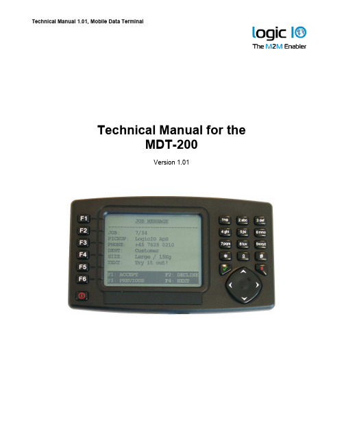
Technical Manual for theMDT-200Version 1.01Logic IO ApS. Ph: (+45) 7625 0210Page 2 of 9IntroductionThis manual contains technical documentation allowing easy installation and use of the unit. For programming information please consult the RTCU Programming Documentation and/or the RTCU IDE Online help.The Mobile Data Terminal (MDT-200) extends the RTCU units (MX2 /DX4/AX9/ M11 series) with a flexible and easy-to-use user interface solution with many advanced features, allowing all kinds of two-way messaging applications to be implemented. The MDT-200 is robust, field proven, and is packed to survive thermal extremes and vibrations.The MDT is easily connected to the RTCU units and includes the following features:• Monochrome Graphical Liquid Crystal Display (LCD) • 320 x 240 pixels resolution (1/4 VGA) • 11 lines with 28 characters.• 21 tactile, user definable keys and a four way cursor. • Built in piezo buzzer.• 10 user selectable backlight and contrast levels. • Two easy mounting options. • High-level VPL library.• Simulator support in RTCU-IDE. • Built for tough environments. • Easy vehicle installation.• MDT on/off and standby functionality.Table of ContentsIntroduction..........................................................................................................................2 Table of Contents ................................................................................................................2 Graphical view.....................................................................................................................3 External connections............................................................................................................4 Overview..........................................................................................................................4 Connector ‘2’....................................................................................................................4 Connector ‘1’ & Connector ‘3’...........................................................................................4 Installation............................................................................................................................5 MX2/DX4..........................................................................................................................5 AX9..................................................................................................................................6 M11 Series.......................................................................................................................7 Power and standby modes...............................................................................................7 Mounting..............................................................................................................................8 Flexible suction cup..........................................................................................................8 M3 mounting holes...........................................................................................................8 Specifications for the Mobile Data Terminal. (9)Logic IO ApS. Ph: (+45) 7625 0210Page 3 of 9Graphical viewFigure 1: Front view7 tactile keysLarge easy-to-read display(11 x 28)14 tactile keys4 way cursorM3 Brass insertBuzzerM3 Brass insertSlot for suction bracket cupFigure 2: Back viewLogic IO ApS. Ph: (+45) 7625 0210Page 4 of 9External connectionsOverviewThe MDT-200 uses a serial interface to communicate with the RTCU unit. Supply for the MDT-200 is also fed into the serial connector on the MDT-200. On the unit are three connectors, only one used is connector ‘2’. See Figure 3 for placement of connectors.Connector ‘2’The unit needs an external DC power source this has to be connected to the interface cable. The supply voltage must be 8-30VDC and connected to the red (positive) and black (ground) wires on the interface cable.Connector ‘1’ & Connector ‘3’Not used.Connector ‘1’ Not used (blinded)Connector ‘3’ Not used Connector ‘2’Figure 3: Bottom viewLogic IO ApS. Ph: (+45) 7625 0210Page 5 of 9InstallationThe interface cable provided in the MDT-200 package is made by Logic IO. The external supply wires and data signal blue (MX2/DX4/AX9) / grey (M11) cable are wired into one (black ) cable to the MDT-200 unit. The total length of the cable is ~3.5m see the figure 4 below for details.Figure 2: MX2/DX4/AX9 Cable dimensionsMX2/DX4The blue cable must be inserted into serial port 2 on the MX2/DX4 unit, the black end must be inserted into connector ‘2’ on the MDT-200 unit, see figure 3 for placement of connector ‘2’ on the MDT-200. For further information on external connections on the MX2/DX4, see their Technical Manual.Figure 3: MX2 Cable~3m~0.5m~0.5mLogic IO ApS. Ph: (+45) 7625 0210Page 6 of 9AX9The blue cable must be connected to serial port 2 on the AX9 unit, the black end must be inserted into connector ‘2’ on the MDT-200 unit, see figure 3 for placement of connector ‘2’ on the MDT-200. For further information on external connections on the AX9, see AX9 Technical Manual.Figure 4: AX9 CableAs the MDT-200 cable not delivered with RJ45 connector at the end of the blue cable, the color coded cable needs to be connected to the AX9 manually. Cables are color coded, and these colors will be used in the following description:Figure 5 AX9 cable close-upAs seen on the above picture, there are 4 signals to be connected to the AX9 Pro. The cable colors and the signal names on the AX9 Pro are given in the following table:Signal Name Blue SGND Blue/white SER2_RXD Green SER2_TXD Brown SER2_RTSLogic IO ApS. Ph: (+45) 7625 0210Page 7 of 9Connect the 4 colored cables to their respective labeled angled screw terminals asmentioned in the table in the previous page. Please refer to AX9 Pro Technical Manual to locate the terminals.M11 SeriesThe grey cable must be inserted into serial port 2 on the M11 unit, the black end must be inserted into connector ‘2’ on the MDT-200 unit, see figure 3 for placement of connector ‘2’ on the MDT-200. For further information on external connections on the M11 series, see the appropriate M11 Technical Manual.Figure 6: M11i / M11Gi CablePower and standby modesThe MDT-200 has two power modes with different behaviors and power consumption:• Power : Controls the DC supply for the MDT-200, if turned off it’s not possible to usethe keys, this way the MDT-200 must be turned on from the software. In this state the power savings are at maximal.• Standby : In standby mode the display will be turned off, this way it looks like theMDT-200 is turned off, but it’s possible to turn on the MDT-200 on the keys. Power savings are minimal in this state.For more information on this subject please consult the RTCU Programming Documentation and/or the RTCU IDE Online help.Logic IO ApS. Ph: (+45) 7625 0210Page 8 of 9MountingThere are two ways to mount the MDT unit these are described below.Flexible suction cup.1. Match the two slides on the bracket to the corresponding slots on the back of theMDT-200 unit until they firmly latch into place. 2. Find a smooth surface and clean it thoroughly.3. Press the suction cup firmly to the surface while pulling the lever down to seal the suction cup.4. Hold the bracket base and bend the stalk to adjust the viewing position.M3 mounting holes.The brass inserts on the backside can be used to mount the MDT on a custom made bracket. There are four M3 mounting holes available, see figure 6 below for guidance. Be careful not to over tighten the screws as driving the screws in too far may cause damage, therefore use M3x6mm screws. Too use the mounting holes the slot for the suction cup must be removed.Figure 6: M3 brass inserts placementsSpecifications for the Mobile Data TerminalPage 9 of 9 Logic IO ApS. Ph: (+45) 7625 0210。

广州致远电子有限公司类别内容关键词 CANET 、以太网、CAN 摘 要修订历史版本日期原因V1.00 2008/03/21 创建文档V1.01 2008/09/10 更新文档V1.02 2009/02/03 更新文档销售与服务网络(一)广州周立功单片机发展有限公司地址:广州市天河北路689号光大银行大厦12楼F4邮编:510630电话:(020)38730916 38730917 38730972 38730976 38730977传真:(020)38730925网址:广州专卖店地址:广州市天河区新赛格电子城203-204室电话:(020)87578634 87569917传真:(020)87578842 南京周立功地址:南京市珠江路280号珠江大厦2006室电话:(025)83613221 83613271 83603500 传真:(025)83613271北京周立功地址:北京市海淀区知春路113号银网中心A座1207-1208室(中发电子市场斜对面)电话:(010)62536178 62536179 82628073传真:(010)82614433 重庆周立功地址:重庆市石桥铺科园一路二号大西洋国际大厦(赛格电子市场)1611室电话:(023)68796438 68796439传真:(023)68796439杭州周立功地址:杭州市天目山路217号江南电子大厦502室电话:(0571)28139611 28139612 2813961328139615 28139616 28139618传真:(0571)28139621 成都周立功地址:成都市一环路南二段1号数码同人港401室(磨子桥立交西北角)电话:(028)85439836 85437446传真:(028)85437896深圳周立功地址:深圳市深南中路 2070号电子科技大厦C座4楼D室电话:(0755)83781788(5线)传真:(0755)83793285 武汉周立功地址:武汉市洪山区广埠屯珞瑜路158号12128室(华中电脑数码市场)电话:(027)87168497 87168297 87168397传真:(027)87163755上海周立功地址:上海市北京东路668号科技京城东座7E室电话:(021)53083452 53083453 53083496 传真:(021)53083491 西安办事处地址:西安市长安北路54号太平洋大厦1201室电话:(029)87881296 83063000 87881295传真:(029)87880865销售与服务网络(二)广州致远电子有限公司地址:广州市天河区车陂路黄洲工业区3栋2楼邮编:510660传真:(020)38601859网址:(嵌入式系统事业部)(工控网络事业部)(楼宇自动化事业部)技术支持:CAN-bus:电话:(020)22644381 22644382 22644253 邮箱:****************************iCAN及数据采集:电话:(020)28872344 22644373 邮箱:*********************MiniARM:电话:(020)28872684 28267813邮箱:******************************以太网:电话:(020)22644380 22644385邮箱:*********************************无线通讯:电话:(020) 22644386邮箱:*************************串行通讯:电话:(020)28267800 22644385 邮箱:***********************编程器:电话:(020)22644371邮箱:*************************分析仪器:电话:(020)22644375 28872624 28872345 邮箱:********************ARM嵌入式系统:电话:(020)28872347 28872377 22644383 22644384 邮箱:**********************楼宇自动化:电话:(020)22644376 22644389 28267806 邮箱:*************************************************销售:电话:(020)22644249 22644399 22644372 22644261 28872524 28872342 28872349 28872569 28872573 38601786维修:电话:(020)22644245目录1. 功能简介 (3)1.1 概述 (3)1.2 特性 (4)1.2.1 强大的硬件 (4)1.2.2 完善的功能 (4)1.3 产品规范 (4)1.3.1 LAN (4)1.3.2 CAN (5)1.3.3 软件特性 (5)1.3.4 电气参数 (5)机械尺寸 (6)2. 产品硬件接口说明 (7)2.1 外观图 (7)2.2 电源接口 (7)2.3 以太网接口 (8)2.4 恢复出厂设置按钮 (8)2.5 CAN口 (8)2.6 LED指示灯 (9)3. 硬件连接使用说明 (11)4. 快速使用说明 (12)4.1 设备IP出厂设置 (12)4.2 用户获取设备IP (12)4.3 PC机与设备网段检测 (13)4.3.1 Windows98/Me网络设置 (13)4.3.2 Windows2000/XP网络设置 (15)4.4 CANET-200T与USBCAN接口卡通信 (17)5. 工作模式 (23)5.1 TCP Server模式 (23)5.2 TCP Client模式 (23)5.3 UDP模式 (24)6. ZNetCom软件配置 (25)6.1 安装配置软件 (25)6.2 获取设备配置信息 (26)6.3 修改设备配置信息 (28)6.4 保存恢复设置 (35)6.4.1 保存设置 (35)6.4.2 恢复设置 (36)6.5 升级固件 (36)7. 冗余功能介绍 (40)7.1 以太网网络冗余原理 (40)7.2 CAN网络冗余原理 (41)7.2.1 冗余方案一 (42)7.2.2 冗余方案二 (43)8. 附录 (45)TCP和UDP中默认已经被占用的端口列表 (45)CANET-200T数据转换格式 (47)9. 产品问题报告表 (49)10. 产品返修程序 (50)11. 声明 (1)1. 功能简介1.1 概述CANET-100T/200T 是广州致远电子有限公司开发的一款工业级以太网CAN-bus 数据转换设备,它内部集成了一路/两路CAN-bus 接口和一路EtherNet 接口以及TCP/IP 协议栈,用户利于它可以轻松完成CAN-bus 网络和EtherNet 网络的互连互通,进一步拓展CAN-bus 网络的范围。


李庆明:打造高端存储设备领头羊——PCIe/PXIe接口外置高速大容量存储设备发布时间:2022-10-26T07:06:24.220Z 来源:《中国科技信息》2022年第6月12期33卷作者:陈璐[导读] 在社会经济及科学技术发展的支持下,我国高端存储设备及技术已经得到了完善作者:陈璐单位:藤曼科技发展有限公司邮编:518116在社会经济及科学技术发展的支持下,我国高端存储设备及技术已经得到了完善,促进了我国高端存储领域发展。
李庆明作为沃易升科技(北京)有限公司高速大容量存储项目经理,兼任公司总经理,一直从事高端存储设备研发工作,对我国未来的高端存储市场充满信心,他认为“基于PCIe/PXIe接口的外置高速大容量存储设备”具有非常广阔的市场前景,能够打破国内高端存储市场被国外品牌垄断的僵局。
高端存储市场现状EMC、IBM、NetApp、HP等国外品牌在国内高端存储市场占据主导地位。
在国内与同行业技术水平相当的外国品牌还有NAS和SAN 等,使国内高端存储市场处于群雄争霸的状态。
国内市场占有率较高的国内品牌为华为、浪潮、曙光。
根据IDC预测,全球数据总量将从2018年的33ZB增长至2025年的175ZB。
面临数据的爆发式增长,市场需要更多的存储器承载海量的数据。
参与重大项目李庆明2014年加入沃易升科技(北京)有限公司,担任总经理。
他曾负责高速大容量存储设备项目,产品已完成开发、小批中试工作。
经过两年的潜心钻研,李庆明带领团队于2015年7月正式发布了基于PCIe/PXIe接口的外置高速大容量存储设备,此产品一举填补了国内的市场空白。
紧盯高端存储领域痛点及难点大力创新产品李庆明认为“对于中小科技企业,尤其是投入开发外部存储设备而言,一定要谋求差异化定义,细分市场”。
他指出目前的Block/NAS/SAN网络存储设备并不能很好的解决特定客户需求,这主要体现在:一是存储速率不够高,不能满足用户的刚性存储带宽要求,如实现5GB/s以上的存储速率;二是价格极其昂贵,如EMC满足相关需求的存储设备价格高达七位数人民币以上;三是设备占用空间大,都是以FC和IP存储作为当前主要解决方案,需要配置多余的交换设备作为代价。

Silvertel1 Table of Contents1Table of Contents 1 2Table of Figures 1 3Kit Contents 2 4Introduction 2 4.1EvalAg6700 (2)4.2EvalAg5700 (2)5Evaluation Board Description for Ag6700 3 5.1Input Selection (3)5.2Input Switch (3)5.3Ag6700 Information (4)6Evaluation Board Description for Ag5700 4 6.1Input Selection (4)6.2Input operation (4)6.3Output Adjustment (5)6.4Diode Selection (5)6.5Heat Sink (5)6.6Ag5700 Information (6)7Set-up 6 7.1Power Supply Input (6)7.2Data Input (7)2 Table of FiguresFigure 1: Board Layout (3)Figure 2: Board Layout (4)Figure 3: Output Adjustment (5)Figure 4: Basic set-up (6)Figure 5: Laptop Setup (7)3 Kit ContentsAg5700 Evaluation BoardAg5700 PD ModuleAg6700 Evaluation BoardAg6700 PSE ModuleHeat sink attached to Ag5700 Evaluation Board4 IntroductionThis manual is intended to be a guide to using the “EVALAg5700 evaluation board” along with the “EVALAg6700 evaluation board” with the following Silver Telecom Power Over Ethernet (POE) modules.4.1 EvalAg6700The EVALAG6700 evaluation board can be powered from a 58V power supply suitable of delivering up to 60V at 5A.The data is supplied to the EVALAG6700 through connector J2 and is passed through the data transformer and through to J3. The output power from the PSE is sent to the Ag5700 via J3 (see Figure 1). When the Ag6700 input is on, LED1 will be illuminated. When the PSE module output is on, LED2 will be illuminated.The EVALAG6700 evaluation board will work with the following PSE module: -Ag67004.2 EvalAg5700The EVALAG5700 evaluation board can be powered from the EVALAg6700 evaluation board that provides 58Vdc and up to 4A to the EVALAg5700 board through connector J1.The data and power input to the EVALAG5700 is supplied from the EVALAG6700 to the EVALAG5700 via connector J1 (see Figure 2). Data is passed through the data transformer and through to the data output of connector J2.The output power from the Ag5700 is supplied to the connectors JP1, JP2 and JP3 (see Figure2), where JP2 provides the positive +24Vdc and JP3 provides the ground path of 0Vdc.When there is power connected to the EVALAg5700 board then LED1 will be illuminated. LED2 will be illuminated when the PD module outputs +24Vdc.The EVALAG5700 evaluation board will work with the following PD module: -Ag57005 Evaluation Board Description for Ag67005.1 Input SelectionThe EVALAG6700 evaluation board should be powered using a DC Power supply delivering +58V to either JP1 or pin 1 of J1 and 0V to either JP2 or pin 2 of J1. If LED1 is illuminated then there is power going to the Ag6700 input.Figure 1: Board Layout5.2 Input SwitchApplying the power to the Ag6700 is achieved by switching SW1-1 (ENABLE) into the ON position. The output power is limited to 20W when the CONTROL switch SW1-2 is OFF. To obtain full power from the Ag6700 (200W), the CONTROL switch must be set to ON.LK1 is connected to the Status pin of the Ag6700, if a link is present LED2 will light to show the current output state of the Ag6700. The output of the Ag6700 is in full operation when LED2 is lit, conveying there is output power. When the LED flashes this symbolizes that a fault has occurred e.g. a short circuit.5.3 Ag6700 InformationFull operating conditions and feature set for the Ag6700 can be found in the Ag6700 datasheet, available from 6 Evaluation Board Description for Ag57006.1 Input SelectionThe EVALAg5700 evaluation board should be powered using the EVALAg6700 evaluation board delivering power and data. If LED1 is illuminated then there is power going to the Ag5700 input.Figure 2: Board Layout6.2 Input operationData and Power is supplied to the EVALAg5700 evaluation board through connector J1 which is sent to the data transformer T1 where the power and data are separated from each other.The data is routed to J2 and the power output goes through the selected diode bridgeU1 (see Diode Selection). Applying the power to the Ag5700 is achieved through the output of the diode bridge via ferrite beads, (which prevent high frequency noise going back up the cable and reduces EMI). The Ag5700 distributes the output power of up to 200W through the 4mm plugs, JP2/JP3 or the screw terminal JP1.6.3 Output AdjustmentThe Ag5700 has an ADJ pin, which allows the output voltage to be increased or decreased from its nominal value. Figure 3: Output Adjustment shows how the ADJ pin is connected.Figure 3: Output AdjustmentLK1 is connected to the ADJ pin for the PD module to either increase or decrease the voltage. When the link is connected to the top and middle pins, the Ag5700 output voltage will be increased to its output of 27V. When the link is connected to the bottom and middle pins of LK1 then the Ag5700 output voltage will be decreased to its minimum of 19.5V.6.4 Diode SelectionDue to the differences in the voltage drop across the various diodes, U1 is pluggable so that a Schottky diode or MOSFET bridge maybe chosen.6.5 Heat SinkAs the Ag5700 is a 200W power supply thermal management is essential, as such it is designed to be used with a heat sink at all times to distribute the heat away from the board so the board can run at full operation.The heat sink attached is 2mm aluminum which covers the whole Eval board. For full details on the thermal management see section 8 of the Ag5700 datasheet under Operating Temperature Range.6.6 Ag5700 InformationFull operating conditions and feature set for the Ag5700 can be found in the Ag5700 datasheet, available from 7 Set-up7.1 Power Supply InputFigure 4 shows the basic set up using the EVALAG5700 evaluation board along with the EVALAG6700 evaluation board with a power supply input to JP1.The equipment required: -Power supply Input +58V IN e.g. Meanwell SP-240-48 available form mouser which will give 56VEthernet Data Cable (CAT5e cable) Input and OutputCAT5e or CAT6 interlink cable(between EvalAg6700 and EvalAg5700)Output power cableFigure 5: Laptop Setup7.2 Data InputTo pass data via the Evaluation boards, the data input e.g. Internet, can be connected to J2 on the Ag6700 Eval Board using a cat5e cable. The data is then passed through the data transformer, where power is added and sent out via connector J3 of theAg6700 Eval Board. The Data and power is extracted through J1 of the EVALAg5700 board and then divided into its separate power and data through the data transformer. The data output is then available from J2 of the EvalAg5700 Board, which can then be connected to your device.。

广州致远电子股份有限公司类别 内容关键词 CAN-bus ,CANopen ,主站卡摘 要说明CANopen 协议通讯卡用作为CANopen 主站设备时的具体操作步骤。
修订历史版本日期原因V1.00 2015/01/15 创建文档目录1. 功能简介 (1)1.1主要性能 (1)1.2产品外观 (1)2. 硬件说明 (3)2.1硬件结构 (3)2.2机械尺寸 (3)2.3电气特性 (4)2.4接口定义 (4)2.5CAN-bus连接器 (4)2.6指示灯状态说明 (5)2.7终端电阻 (7)3. 设备安装 (8)3.1硬件安装 (8)3.2驱动安装 (8)3.3卸载设备驱动 (12)4. 测试软件使用说明 (14)5. 二次开发说明 (22)5.1API开发 (22)5.2组态应用 (22)6. 免责声明 (23)1. 功能简介PCI-5010-P 主站卡是集成1路CAN通道,可以连接CAN总线并实现CANopen协议的数据通讯。
接口卡的CAN通道都集成完全的电气隔离保护、防浪涌保护,抗干扰能力强,是性能稳定、通讯可靠的。
并且提供强大的软件支持,包括CANopen函数库、CANopen测试软件、EDS配置软件、OPC服务器等。
为CANopen网络提供了可靠性、高效率的解决方案。
已经大量应用于风力发电、轨道交通、变频器等CANopen网络领域中的数据采集与数据处理。
本产品配有可在Win2000/XP/WIN7/WIN8、等操作系统下工作的驱动程序,并包含详细的应用例程。
并且提供个性化定制服务。
1.1 主要性能●通用PCI或者USB接口,适用于5V系统;●CAN通道数:1路;●电气隔离:DC 2500V 或者AC 1700V;●CANopen接口支持DS301V 4.02、DS303-3等,通过CIA一致性测试;●最大32个从站、可注册最多128个RPDO、512个TPDO,支持PDO、SDO发送;●支持所有NMT网络管理功能;●主站卡硬件自动存储紧急报文;●支持所有PDO通讯类型,并可实现对每个PDO 的监控;●运行环境:Win9X/Me、Win2000/XP、Vista、win2003、Win7、Win8等操作系统;●ESD(静电放电)保护:IEC 61000-4-2 Level 3(接触放电6KV,空气放电15KV);●CAN通信接口支持2KV、5/100Hz浪涌保护;●工作温度与存储温度:-40℃~+85℃;●物理尺寸:114mm*90mm;●安装方式:便携式或者PCI固定方式;●CAN波特率:符合CANopen规范的波特率——10kbps 20kbps 50kbps 100kbps125kbps 250kbps 500kbps 800kbps 1000kbps;1.2 产品外观PCI-5010-P 产品外观如图1. 1所示:图1. 1 PCI-5010-P产品外观2. 硬件说明2.1 硬件结构PCI-5010-P CANOpen协议通讯卡的硬件由32bit PCI桥、ARM7协议处理器、隔离CAN 接口等单元组成,如图2. 1所示:图2. 1 PCI-5010-P通讯卡的硬件框图2.2 机械尺寸PCI-5010-P通讯卡机械尺寸如图2. 2:图2. 2 PCI-5010-P通讯卡的机械尺寸2.3 电气特性PCI-5010-P CANOpen协议通讯卡具有良好的电气性能,主要参数如表2. 1所示。