PRESENTACION CLUBCARD10 ESPANOL V16-1-1
- 格式:pdf
- 大小:7.96 MB
- 文档页数:30

CPS-HP3Set Manguera 0.9m premiumCPS-HP5Set Manguera 1.5m premiumCPS-HP5E Set Manguera 1.5m premium c/valvulaCPS-HS10Set Manguera 3.0m standarCPS-HS3Set Manguera 0.9m standarCPS-HS5Set Manguera 1.5m standarCPS-HXD Depresor p/manguera 1/4 x 10CPS-HXGA Gomita p/manguera 1/4 antiblowCPS-HXGB Gomitas p/manguera 1/4 x 100CPS-HXTG Junta de teflon p/manguera 1/4 x 10MANIFOLDSADAP1/2ACMEX1/4FH Adaptador rosca Acme flare hembra 1/2"x1/4" p/mang R-134a ADAP1/2ACMEX1/4FM Adaptador rosca Acme flare macho 1/2"x1/4" p/garrafa R-134a ADAP1/4X5/16VR Adaptador 1/4"FM x 5/16"FH c/valvula retención UNIWELD 92863 CPS-M2TP3Manifold R-22 y R-407 c/mangueraCPS-M2YP3Manifold R-22 y R-404 c/mangueraCPS-MBYP3Manifold R-22 y R-407 c/manguera negraCPS-MBZS3Manifold R-22 y R-12 c/manguera negraCPS-MEBP3Manifold R-410 c/manguera rosaCPS-MSTG3Manifold R404A, R22, R134A c/manguera 36" BAR/PSI/CCPS-MT2O7P5S Manifold R410A, R22, R407C c/manguera 36" BAR/PSI/CCPS-MV12B Manifold R-410 c/manguera VORTECHCPS-MV13B Manifold R-410 1/4 VORTECHCPS-MV4Z Manifold R-22 y R-134 VORTECHCPS-MV4ZP5Manifold R-22 y R-134 c/manguera VORTECHMANÓMETROSCPS-RGBH Manómetro R410 alta 68mmCPS-RGBL Manómetro R410 baja 68mmCPS-RGX68BB Protector goma azul 68mmCPS-RGX68L Lente para manometro 68mmCPS-RGX68RB Protector goma rojo 68mmCPS-RGYH Manómetro R22/407 alta 68mmCPS-RGYL Manómetro R22/407 baja 68mmCPS-RGZH Manómetro R22/12 alta 68mmCPS-RGZL Manómetro R22/12 baja 68mmPESTAÑADORAS Y EXPANSORASCPS-FT195Pestañadora 3/16" - 5/8" standarCPS-FT203Pestañadora 5/8" - 1 1/8" standarCPS-FT500Pestañadora 3/16" - 5/8" especialCPS-FT525Pestañadora ajustable 5/8"CPS-TLE6Expansora tubo 3/8" - 1 1/8"CPS-TLH06Reemplazo Cabezal Expansora 3/8"CPS-TLH08Reemplazo Cabezal Expansora 1/2"CPS-TLH10Reemplazo Cabezal Expansora 5/8"CPS-TLH12Reemplazo Cabezal Expansora 3/4"CPS-TLH14Reemplazo Cabezal Expansora 7/8"CPS-TLH16Reemplazo Cabezal Expansora 1"CPS-TLH18Reemplazo Cabezal Expansora 1 1/8"CPS-TLH22Reemplazo Cabezal Expansora 1 3/8"REMOVEDOR DE NÚCLEOCPS-TLVC1Sacaóvulo standar c/4 nucleosCPS-TLVC2Sacaóvulo dual 1/4" + autoCPS-TLVC410A Sacaóvulo R410 c/portCPS-TLVCS Sacaóvulo standar c/portRECUPERADORA DE GASES REFRIGERANTESCPS-CR300S Recuperadora gases economica 220V 282K/h LiqCPS-CR500S Recuperadora gases apta R410 220V 332K/h Liq comp 1/3HP oil less CPS-CR700S Recuperadora gases Cyclone R410 220V 430K/h Liq comp 1HP oil less CPS-TR21S Recuperadora gases liviana R410 220V 858K/h Liq comp 1HP oil less CPS-MT69Acelarador Molecular CPS para recuperadorasTERMÓMETROS DE BOLSILLOCPS-TM50Termómetro digital de bolsillo, rango -58 a 260°CCPS-TMAPC Termómetro analógico de bolsilloCPS-TMDP Termómetro digital de bolsilloCPS-TMINI12Termómetro infrarrojo 8/1VACUÓMETROSCódigo DescripciónCPS-VG100A Vacuómetro digital ledCPS-VG200Vacuómetro digital display。

Commutateur 8 Ports ProSafe avec PoEFS108P 4 PortsFS108PAlluméÉteintVoyant d'alimentationActivité (clignotant)Pas de lien (éteint)Liaison 10 Mbits/s (voyant de droite)Voyants de portLiaison 100 Mbits/s (voyant de gauche)Guide d'installationÉtape 2. Branchez l'alimentation Étape 3. Vérifiez l'étatModem en optionÉtape 1. Connectez l'équipementRouteur en optionOrdinateurServeurInternetVoyants PoEMoins de 7W de puissance PoE disponible.PoE max. VoyantLes ports PoE fonctionnent normalement. (éteint)Le voyant PoE MAX était actif au cours des 2 dernières minutes. (clignotant)PoE utiliséNe pas utiliser PoE (éteint)Panne PoEPanne PoE VoyantSeptembre 2012Ce symbole a été apposé conformément à la directive européenne 2002/96 sur la mise au rebut des équipements électriques et électroniques (directive WEEE - Waste Electrical and ElectronicEquipment). En cas de mise au rebut de ce produit dans un État membre de l'Union européenne, il doit être traité et recyclé conformément à cette directive.NETGEAR, le logo NETGEAR et Connect with Innovation sont des marques commerciales et/ou des marques déposées de NETGEAR, Inc. et/ou des filiales de NETGEAR aux Etats-Unis et/ou dans d'autres pays. Les informations sont sujettes à changement sans préavis. Les autres marques et noms de produits sont desmarques commerciales ou des marques déposées de leurs détenteurs respectifs. © NETGEAR, Inc. Tous droits réservés.Pour une utilisation en intérieur dans tous les pays de l'UE et la Suisse.Pour consulter la déclaration de conformité complète, rendez-vous sur le site /app/answers/detail/a_id/11621/.Conditions : NETGEAR se réserve le droit d'apporter des modifications aux produits décrits dans ce document sans préavis afin d'en améliorer la conception, les fonctions opérationnelles et/ou la fiabilité. NETGEAR décline toute responsabilité quant aux conséquences de l'utilisation des produits ou des configurations de circuits décrits dans le présent document.SpécificationsSpécification DescriptionInterface réseauPorts RJ45 Auto-Uplink 10/100 Mbits/s avec PoE activé (ports 1 - 4)Ports RJ45 Auto-Uplink 10/100 Mbits/s (ports 5 - 8)Câble réseau Catégorie 5e (Cat 5e) ou meilleur câble Ethernet Ports8Adaptateur secteur Entrée CC 48V @ 1,25 ABudgetd'alimentation PoE 53W max. tous les ports PoE (1-4), 15,4 W max. par port PoE Poids 0,74 kg (1,7 lb)Dimensions (L × P × H)235 mm x103 mm x 27 mm 9,3 po. x 4,1 po.x 1,1 po.Température de fonctionnement 0-40 ° C (32-104 ° F)Humidité de fonctionnement 10% -90% d'humidité relative, sans condensationConformitéélectromagnétique CE Classe B; FCC Classe B; VCCI Classe B; C-Tick Classe B, CCC Homologations de sécuritéCE/LVD, CCCSupport techniqueAprès l'installation de votre périphérique, notez le numéro de série inscrit surl'étiquette de votre produit. Il vous sera nécessaire pour enregistrer votre produit à l'adresse https:// .Vous devez enregistrer votre produit avant de pouvoir utiliser l'assistancetéléphonique de NETGEAR. NETGEAR vous recommande d'enregistrer votre produit sur le site Web de NETGEAR. Pour obtenir des mises à jour de produits et accéder au support Web, visitez .。

Geislingen, 05.05.2015Declaration of Compliancefor articles made from metals and alloys as well as plasticintended to come into contact with foodHereby we confirm that our product:Anniversary utility knife 10 cm "Spitzenklasse Plus" Item No.: 18.9586.9992 complies with the legal regulations laid down in the German Commodity Ordinance (or the respective stipulations laid down in the European Regulations on Plastic materials) as well as Regulation (EU) No 10/2011, the Regulation (EC) No 1935/2004 and the Regulation (EC) No 2023/2006, in their relevant versions.Description (material/optics):Forged special blade steel (10 cm) handles made of black Polyoxymethylene (POM), rivetedWhen used as specified, the overall migration as well as the specific migration do not exceed the legal limits; the transition of metal ions does not exceed the SRLs (Specific Release Limits) according to Council of Europe Resolution CM/Res(2013)9 on metals and alloys used in food contact materials and articles (effective 2013 – 1st Edition).The tests are performed according to the Directives 82/711/EEC and 85/572/EEC resp. to the …Technical guide on metals and alloys used in food contact materials and articles“. As from 01.01.2016 the migration tests for plastics according to articles 17 and 18 of Regulation (EU) No 10/2011 in conjunction with Annex V.The materials and raw materials used comply with the German Commodity Ordinance (or the respective stipulations laid down in European Regulations on Plastic materials) as well as the Regulation (EC) No 1935/2004 and the Regulation (EU) No 10/2011, respectively according to the latest version.The following substances, subject to limitations and/or specification are used in the above mentioned product:Name of substance/ CAS-No / Ref.-No SML values / Limits Formaldehyde (POM) ≤ 15 mg/kgpage 1 of 2Declaration of ComplianceWMF AGEberhardstraße 3573312 Geislingen | Steige Germanytelefon +49 7331 25 1 fax +49 7331 45 387email ******************web V ORSIT ZENDE R DES AU F SI CHT SRATES Johannes P. HuthV ORSTA NDPeter Feld | V O RSIT ZENDER Bernd StoeppelS IT Z DER GE SELLS CHAF T Geislingen | SteigeRECHT SF ORMAktiengesellschaftREG ISTE RGE RI CHTUlm HRB 540215WEEE-Reg.-Nr. DE 78426351 USt.-ID.-Nr. DE 298 927 552 St.-Nr. 62050|01072 ILN 4000530 00000 2BAN KVE RBINDUN GCommerzbank AG Göppingen BLZ 610 400 14 KON TO 1 60 3000 00 BI C COBADEFFXXX I BAN DE06 6104 0014 0160 3000 00Version : 1 page 2 of 2Specification of the intended use or limitations:- Type (s) of food intended to come into contact with the article:Universal foodstuffs- Intended duration and temperature of treatment and storage while in contact with the food:Repeated short-term contact also at high temperaturesDual-use-additives are not enclosed.There is no functional barrier used in the plastic material.This declaration is valid for the product delivered by us as specified above. Under consideration of the food contact conditions stated, the product complies with the stipulations of these Directives regarding the specified foods. The user shall verify himself that the product is suitable for the intended food beyond the stipulations of the Directives.The validity of the declaration is ending if the requirements are changed.WMF Württembergische Metallwarenfabrik AktiengesellschaftThis document was created electronically and is valid without signature.Name of the document: WMF_1895869992_EN_20150505 Anniversary utility knife 10 cm Spitzenklasse Plus_sh.docx。
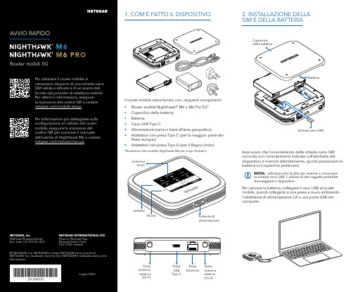
Per caricare la batteria, collegare il cavo USB al router mobile, quindi collegarlo a una presa a muro utilizzando l'adattatore di alimentazione CA o una porta USB del computer.Assicurarsi che l'orientamento della scheda nano SIM coincida con l'orientamento indicato sull'etichetta del dispositivo e inserirla delicatamente, quindi posizionare la batteria e il coperchio posteriore.NOTA: utilizzare solo le dita per inserire o rimuovere la scheda nano SIM. L'utilizzo di altri oggetti potrebbe danneggiare il dispositivo.1. COM'È FATTO IL DISPOSITIVO2. INSTALLAZIONE DELLA SIM E DELLA BATTERIAIl router mobile viene fornito con i seguenti componenti:• Router mobile Nighthawk® M6 o M6 Pro 5G*• Coperchio della batteria • Batteria• Cavo USB Tipo C• Alimentatore (varia in base all’area geografica)• Adattatori con presa Tipo C (per la maggior parte dei Paesi europei)•Adattatori con presa Tipo G (per il Regno Unito)*Illustrazioni del modello Nighthawk M6 per scopi illustrativi.antenna esterna (TS-9)antenna esterna (TS-9)USB Tipo CEthernetCONFORMITÀ NORMATIVA E NOTE LEGALIPer informazioni sulla conformità alle normative, compresala Dichiarazione di conformità UE, visitare il sito Web https:///it/about/regulatory/.Prima di collegare l'alimentazione, consultare il documento relativo alla conformità normativa.Può essere applicato solo ai dispositivi da 6 GHz: utilizzare il dispositivo solo in un ambiente al chiuso. L'utilizzo di dispositivi a 6 GHz è vietato su piattaforme petrolifere, automobili, treni, barche e aerei, tuttavia il suo utilizzo è consentito su aerei di grandi dimensioni quando volano sopra i 3000 metri di altezza. L'utilizzo di trasmettitori nella banda 5.925‑7.125 GHz è vietato per il controllo o le comunicazioni con sistemi aerei senza equipaggio.SUPPORTO E COMMUNITYDalla pagina del portale di amministrazione Web, fare clic sull'icona con i tre puntini nell'angolo in alto a destra per accedere ai file della guida e del supporto.Per ulteriori informazioni, visitare il sito netgear.it/support per accedere al manuale dell'utente completo e per scaricare gli aggiornamenti del firmware.È possibile trovare utili consigli anche nella Community NETGEAR, alla pagina /it.GESTIONE DELLE IMPOSTAZIONI TRAMITE L'APP NETGEAR MOBILEUtilizzare l'app NETGEAR Mobile per modificare il nome della rete Wi-Fi e la password. È possibile utilizzarla anche per riprodurre e condividere contenutimultimediali e accedere alle funzioni avanzate del router mobile.1. Accertarsi che il dispositivo mobile sia connesso a Internet.2. Eseguire la scansione del codice QR per scaricare l'appNETGEAR Mobile.Connessione con il nome e la password della rete Wi-Fi 1. Aprire il programma di gestione della rete Wi‑Fi deldispositivo.2. Individuare il nome della rete Wi‑Fi del router mobile(NTGR_XXXX) e stabilire una connessione.3. Only Connessione tramite EthernetPer prolungare la durata della batteria, l'opzione Ethernet è disattivata per impostazione predefinita. Per attivarla, toccare Power Manager (Risparmio energia) e passare a Performance Mode (Modalità performance).4. CONNESSIONE A INTERNETÈ possibile connettersi a Internet utilizzando il codice QR del router mobile da uno smartphone oppure selezionando manualmente il nome della rete Wi‑Fi del router e immettendo la password.Connessione tramite codice QR da uno smartphone 1. Toccare l'icona del codice QR sulla schermata inizialedello schermo LCD del router mobile.NOTA: quando è inattivo, lo schermo touch si oscura per risparmiare energia. Premere brevemente e rilasciare il pulsante di alimentazione per riattivare lo schermo.3. CONFIGURAZIONE DEL ROUTER MOBILETenere premuto il pulsante di accensione per due secondi, quindi seguire le istruzioni visualizzate sullo schermo per impostare un nome per la rete Wi‑Fi e una password univoci.La personalizzazione delle impostazioni Wi‑Fi consente di proteggere la rete Wi‑Fi del router mobile.Impostazioni APNIl router mobile legge i dati dalla scheda SIM e determina automaticamente le impostazioni APN (Access Point Name) corrette con i piani dati della maggior parte degli operatori. Tuttavia, se si utilizza un router mobile sbloccato con un operatore o un piano meno comune, potrebbe essere necessario immettere manualmente le impostazioni APN.Se viene visualizzata la schermata APN Setup Required (Configurazione APN richiesta), i dati APN dell’operatore non sono presenti nel nostro database ed è necessario inserirli manualmente. Immettere i valori fornitidall’operatore nei campi corrispondenti, quindi toccare Save (Salva) per completare la configurazione.NOTA: l’operatore determina le proprie informazioni APN e deve fornire le informazioni per il proprio piano dati. Si consiglia di contattare il proprio operatore per le impostazioni APN corrette e di utilizzare solo l’APN suggerito per il piano specifico.Schermata inizialeAl termine della configurazione, il router visualizza la schermata iniziale:Wi‑FiPotenza Carica Rete Codice QR connessione rapida Wi‑FiNome e Wi‑FiIcona del codice QR。

How to Make Iced CoffeeThere are two simple ways to prepare flavorful iced coffee that doesn’t get watered down:1.Brew the coffee double strength and pour into a glass of ice.2.Prepare coffee ice cubes ahead of time and brew the coffee normal strength.Double Strength Brewing:For Capresso 10-cup coffee makers, place 10 scoops of ground coffee in the gold-tone filter and fill the water tank with 5 cups of water. The extra ground coffee in the filter will give the brewed coffee twice the strength and when ice is placed in the glass and starts to melt, it will not water down the iced coffee as it is double brewed. Adjust coffee strength to taste by adding or subtracting the number of coffee scoops or adjusting the water quantity.Coffee Ice Cubes:If you do not enjoy the double strength brewed iced coffee, you can also make coffee iced cubes by simply filling an ice cube tray with coffee and freezing it overnight. Prepare the drip coffee as you normally would and pour coffee over the coffee ice cubes. When the ice cubes melt, they will not dilute the iced coffee.Additional Tips:•Always add sugar and milk to the coffee while it is hot. The sugar will dissolve better and the cold milk will help cool down the coffee faster.•In lieu of sugar, add flavorings such as vanilla syrup, chocolate syrup, hazelnut syrup or almond extract to create a specialty iced coffee. The syrups will sweeten up the coffee while adding a hint of flavor. They also dissolve better in liquid than coarse sugar.•Try sweetened condensed milk or coconut milk for a different twist on iced coffee.•For even colder iced coffee, place the brewed coffee in a covered container in the refrigerator for one to two hours before serving or even overnight. This will cool down the coffee completely and help reduce ice melting inside the glass. Do not place the hot coffee carafe directly in the refrigerator as it could causedamage to the carafe.•Want colder iced coffee without waiting? Add coffee, milk, sugar/sweetener and ice to a cocktail shaker and shake. Strain iced coffee into a glass with even more ice and serve.。


*1010R16/P(CTS MCS-16C)Card RackGeneral Purpose 16 CardFront Load RackCopyright© 2000 Patton Electronics Co., All Rights ReservedAn ISO-9001Certified CompanyDoc#: 152001UA Part#: 07M1010R16-ARackmount InstallationT he rackmount cards install in the card rack for central site installation. The card rack can accommodate up to 16 cards. Before installing the rackmount cards into the rack, the supplied personality module must be installed in the back of the Rack. See below for module types.The tab of the personality module is placed in the appropriate slot on the back of the Card Rack. The reason for this installation is to provide the cable termination between the two peripheral devices and the rackmount card. Once the module has been placed into the slot, be sure to secure the module to the rack with the supplied fastening screw. After installing the personality module, the rackmount card can be placed in the rack by sliding the card into the front of the Card Rack. Cards may be removed from the rack without removing the cables or powering off the Card Rack.Once the Personality module and rackmount card have been installed, configure the rackmount cards. Configuration settings are explained in the units operations manual provided with the rackmount card.The Card Rack is supplied with an internal power transformer capable of suppling 6 Amps of current. In the event one card should fail, a self correcting device on the power bus will isolate that card allowing the remaining cards to operate correctly.Card Rack with Personality Modules InstalledTechnical SpecificationsApplications : Multiple Interfacecards in a data center can bemounted in a 19” rack to conservespaceCapacity: 16 CardsPower Source: 100-120/200-240VAC, 50 to 60 Hz, 0.8/0.4A,Switch SelectableApprovals:Environmental: Operating Temp:32° to 122° (0° to 50°C); Relative Humidity: 5 to 90% non-conduct-ing; Altitude: 0 to 10,000 feet Dimensions: Height: 6.96 inches;Width: 19.00 inches; Depth: 9.88inches Weight: 4.5 lbs* Switch fuse for 100-120V (0.8ASB, 250V) 200-240V (0.4ASB, 250V) as noted on the power supply.Caution: The RJ-45 connectors should never be connected to the Public Telephone Network.CE NOTICE: The CE symbol on your Patton Electronics equipment indicates that it is in compliance with the Electromagnetic Compatibility (EMC) directive and the Low Voltage Directive (LVD) of the Union European (EU). A Certificate of Compliance is available by contacting Technical Support.*7622 Rickenbacker DriveGaithersburg, MD 20879Sales: 301 975-1000 Support: 301 975-1007 Web Address: 。

OCA-P181610Outdoor Cabinet Assembly18 x 16 x 10” Polycarbonate Enclosure for OutdoorSwitchesInstall GuideContentsFeatures (2)Specifications (2)Regulatory Agency Compliance (2)Base Cabinet Compliance (2)Ordering Information (3)Related Manuals (3)Dimensions (4)Components (5)Product Views (6)Install Procedures (7)Ground Terminal Blocks Together (7)If Using an AC Power Source (9)Cutting and Reconnecting AC Power Cord within Enclosure (9)Connecting DC Power within the Enclosure (9)Connecting the Magnetic Door Contact Switch (10)Cautions and Warnings (10)Installing the OCA-PMK-26 Option (11)Record of Revisions (14)Contact Us (14)Transition Networks’ Outdoor Cabinet Assembly is a high impact resistant polycarbonate enclosure with a hinged cover that permits a 225° door swing and allows for easy door removal during installation or maintenance. The door is secured by two stainless steel latches that are bolted in place (providing more security than pop rivets or slide-on latches) and can be further secured with pad locks (not included). The 18” x 16” x 10” cabinet is deep enough to protect the bend radius of fiber cables connected to nearly any Transition Networks temperature hardened switch when mounted in the enclosure. A liquid tight vent is included to prevent condensation inside the enclosure.Inside the cabinet, the OCA-P181610 includes two 15” DIN rails for easily mounting switches, media converters, power supplies and other communications equipment (sold separately). One entry port for routing power wires (a receptacle can be added) and 10 data cable entry ports with cord grips (each data cord grip accommodates two cables) are pre-installed in the cabinet. The enclosure also includes a ground terminal block with four push-in connections on each DIN rail to protect against lightning or other surges in power to the enclosure. Red and black feed-through terminal blocks are provided for terminating low voltage DC positive and negative wires within the enclosure. Blue and white feed-through terminal blocks are provided for AC mains line andneutral/line connections. End caps are also included for added safety.The enclosure includes mounting feet for mounting on a wall or side of a building. Optional brackets are available for mounting on 2-6" diameter poles. The optional EDCA-DIO-01 mounts easily on the DIN rails or to the side of the cabinet with optional wall mount brackets. Optional fiber management trays (SESPM-4P-FMT) are available for managing fiber cable, if needed.Features•Light weight, high impact resistant polycarbonate cabinet•Wide swing or removable hinge for easy access•Bolted latches•Vent to prevent condensation inside the enclosure•Wall or pole mount (optional)•Enclosure door contact alarm (optional)•Fiber management trays (optional)•Wide operating temperature range•Made in USASpecificationsRegulatory Agency ComplianceBase Cabinet ComplianceStandard(s) for Safety: Standard for Enclosures for Electrical Equipment, UL 50UL 50E ENCLOSURES FOR ELECTRICAL EQUIPMENTCSA C22.2 NO. 94.1.07 ENCLOSURES FOR ELECTRICAL EQUIPMENT, NON-ENVIRONMENTAL CONSIDERATIONS CSA C22.2 NO. 94.2-07 ENCLOSURES FOR ELECTRICAL EQUIPMENT, ENVIRONMENTAL CONSIDERATIONSRoHS, WEEE, and Environmental Programs: See https:///rohs-weee-environmental-programs/.Ordering InformationRelated Manuals•SISPM1040-384-LRT-C and SISPM1040-362-LRT Quick Start Guide, Install Guide, Web User Guide, and CLI Reference (33726 – 33729)•SISPM1040-582-LRT Quick Start Guide, Install Guide, Web User Guide, and CLI Reference (33754 - 33757) •PS-DC-DUAL-5624T Power Supply QSG (33792) and PS-DC-DUAL-5624T Power Supply Install Guide (33788) •EDCA-DIO-01 Quick Start Guide (33796) and EDCA-DIO-01 Install Guide (33790)•OCA-PMK-26 Quick Install Guide, 33820•WMB-EDCA: see the EDCA-DIO-01 Install Guide (33790)•SESPM-4P-FMKIT Option Install Guide (33775)•Power Supplies: 25104, 25105, 25160 and PS-DC-DUAL-56xxTDimensionsComponentsCheck the package contents to make sure you have received the following items. Contact your sales representative if any item is damaged or missing. Please save the packaging for possible future use.•One 18x16x10” NEMA 4X/IP66 polycarbonate cabinet•Two DIN Rails (installed)•Two Ground Terminal Blocks (installed)•One each Red and Black Terminal Blocks for DC +/- Wires (installed)•One each Blue and White Terminal Blocks for AC Mains Line and Neutral/Line Connections (installed) •One Power Wire Gland (installed) (see Note 1 below)•Ten Data Wire Glands (accommodate 2 Cables each) (installed) (see Note 2 below)•One 22365 Magnetic Door Contact Switch (installed)•Nine 22339 Hole Plugs•Nine 22338 Hole Plugs•Six Terminal Block 22381 End Caps (3 installed, 3 extras provided to be inserted for safety if terminal blocks are separated from initial configuration)Note 1: Power Wire Gland (x1): Using Torque Wrench, tighten nuts to 75-80 in. lbs.Note 2: Data Wire Glands (x10): Using Torque Wrench, tighten nuts to 75-80 in. lbs.Product ViewsInstall ProceduresGround Terminal Blocks TogetherGround terminal blocks are provided on both the upper and lower DIN rails. For added safety, it is recommended that these ground terminal blocks be tied to together.Note: Switch and power supply shown for illustration purposes only (sold separately).Terminal Block DetailsIf Using an AC Power SourceIf using an AC power source, you must either cut off the plug and terminate the wires as you would a DC power source or add a receptacle (not provided). If adding a receptacle, the vent and power gland can be swapped to better accommodate a receptacle.If using molded power cords, the IEC C1x type equipment connector will not pass through the wire glands provided with the enclosure. The connector can be cut from the cord per the below instructions; push-on terminal blocks are provided to reconnect the wires from the cord. There are typically three insulated wires:•green for earth (chassis) ground connection•white for neutral in 110VAC systems (or second leg in 220VAC systems)•non-white (black/blue/red) for the line (hot) in 110VAC (or first leg in 220VAC systems)Cutting and Reconnecting AC Power Cord within Enclosure1.Determine the length of stub connection needed to reach from the IEC C1x connector attached to theequipment to the green, white and blue terminal blocks. Make sure to allow enough extra length to providea drip loop in the event that any moisture that potentially entered the enclosure while servicing theequipment during inclement weather with the enclosure door open will not allow for water droplets to run down the power cord wires and into the terminal blocks.2.Cut the power cord to the desired length.3.Pass the cut end of the AC mains wire from the outside of the enclosure through the strain relief/wire glandto the inside of the enclosure.4.Strip the outer sheath of both ends of the power cord to expose enough individual wire length forconnecting to the terminal blocks and allowing extra length for drip loops.5.Strip the insulation on each wire back approximately 0.25" (6mm). After stripping the insulation, twist thestranded wire ends to facilitate insertion of the wire into the terminal block.6.Attach the green wires on both cut ends of the power cord to the green earth (chassis) ground terminalblock: push and hold the orange wire release button while inserting wire, then release to secure connection.7.Attach the white wires on both cut ends of the power cord to the white terminal block.8.Attach the non-white wires on both cut ends of the power cord to the blue terminal block.Connecting DC Power within the Enclosure1.Strip the insulation on each wire back approximately 0.25" (6mm).2.Twist the stranded wire ends to facilitate insertion of the wire into the terminal block.3.Insert ground (green) wire into green terminal block. Push and hold the orange wire release button whileinserting wire, then release to secure connection.4.Insert DC positive (red) wire into red terminal block.5.Insert DC negative (black) wire into black terminal block.Connecting the Magnetic Door Contact SwitchA magnetic door contact switch is included in the cabinet. Use of the door contact switch typically requires a 12-24VDC power source. The Transition Networks PS-DC-DUAL-5624T Dual Industrial Power Supply or the EDCA-DIO-01 Enclosure Door Contact Alarm can provide the required power for the door contact switch. Follow the instructions in your Ethernet Switch manual (if Ethernet Switch includes alarm input/outputs) or the optional Enclosure Door Contact Alarm manual for connecting alarm input/outputs to the door contact switch.Note: If making further modifications to this cabinet, please note the following Cautions and Warnings. Cautions and WarningsWarning: Cancer and Reproductive Harm. See https:///.Use Listed Conduit Hubs or connectors with environmental rating appropriate for the end-use.For Type 2 and/or 3R installations a drain hole is required to be installed in the lowest part of the bottom wall of the enclosure with the size of 1/8” min. to ¼” max.Models ending in 6P require the use of 4 corner screws, torqued to 10 in-lbs, in order to maintain the 6 or 6P rating.Bonding between connections is not automatic and must be provided as a part of the installation.Installing the OCA-PMK-26 OptionThe OCA-PMK-26 is an optional Universal Pole Mount Kit for mounting the OCA-P181610 onto 2-6" diameter poles. The kit is ordered and packaged separately.OCA-PMK-26 Option Part ListOCA-PMK-26 Option DimensionsNote: Only one of two Struts shown:I 2 Hose Clamp 3”OCA-PMK-26 Option Install Procedure1.Attach Band Clamp Brackets (E) or (F) (x2) to inside of Strut Rails (A) (x2) and secure with Pan Head Screws x½” Long (D), Fender Washers (C), & Nylok Nuts (E) (x4). Torque to 32 in-lbs Max.2.Attach Strut Rails to the Enclosure mounting bosses and s ecure with Pan Head Screws x ½” Long (D), andFender Washers (C) (x4). Torque to 32 in-lbs Max.3.Feed Hose Clamp (G) or (H) or (I) (x2) through slots in Band Clamp (E) or (F) (x2), typical.OCA-PMK-26 Option Installed ViewsContact UsTransition Networks10900 Red Circle DriveMinnetonka, MN 55343, U.S.A.tel: +1.952.941.7600 | toll free: 1.800.526.9267 | fax: 952.941.2322******************** | ************************** | ******************************。

Comptec10/2023Desk-top cases –Comptec|5.100OVERVIEW MAIN KATALOGCabinets . . . . . . . 1Wall mountedcases . . . . . . . . . 2 Accessories for cabinets and wall mounted cases . . 3Climate control . . 4Electronicscases . . . . . . . . . 5Subracks/19" chassis . . . . . 6Front panels,plug-in units . . . . 7Systems . . . . . . . 8Power supplyunits . . . . . . . . . . 9Backplanes . . . . 10Connectors, front panel component system . . . . . . . 11Appendix . . . . . 1202202003STANDARDS•Internal dimensions in accordance with IEC 60297-3-100•Type of protection IP 20 in accordance with IEC 60529•Protective ground connections in accordance with:DIN EN 50178/VDE 0160DIN EN 62368-1/VDE 0805DIN EN 61010-1/VDE 0411part 1DIN EN 61010-1A2/VDE 0411part 1/A1/SCHROFFSCHROFF PRODUCT CATALOG 12 / 2022Desk-top cases –ComptecOVERVIEW5.101/SCHROFF |CASE TO ACCEPT 19" SUBRACKS OR 19" CHASSIS•Internal assemblies of up to 40 kg•Up to six rows of ventilation slots in the base plate for optimal air inlet •High stability•Front and rear identical, depth-symmetrical construction •With handle strip or recessed grip0220200402202005SERVICEPLUSe.g. modifications (cut-outs, special colours)e.g. custom solutions (special sizes)e.g. assembly service from 1 pieceOverview . . . . . . 5.100comptec3, 4 U, St . . . . . . . . . 5.1026, 7, 9 U, St . . . . . . 5.1039, 12 U, Al . . . . . . . . 5.104AccessoriesFolding handle . . . 5.105Slide rails . . . . . . . . 5.105Earthing kit . . . . . . 5.106Assembly kit . . . . . 5.106Tip-up feet . . . . . . . 5.107CASE•Al die-cast frame front and rear•Top cover and base plate can be subsequently removed•Top cover and base plate fitted with hidden GND/earth connections •Case height 3, 4, 6, 7 and 9 U (cladding parts in sheet metal)•Case height 9 U and 12 U (cladding parts in aluminium)Desk-top cases–Comptec|ORDER INFORMATIONNOTE•Please order GND/earthing kit separately, see page 5.106•The case foot, item 10, can be replaced by a tip-up foot,see page. 5.107•Please order slide rails separately, see page 5.10519" CASE, 3U, 4U02202001CTTP0001Front viewCTA42313Usable width b = B - 69 mm, h = height of case footItem Qty Description11Front frame, Al die-cast, RAL 7016, with 19" grid21Rear frame, Al die-cast, RAL 7016, with 19" grid52Side panel, Al extrusion, RAL701671Cover plate, Al, 1 mm, RAL 9006,with GND/earthing tag81Base plate, Al, 1 mm, RAL 9006,with GND/earthing tag91Rear panel, St, 1mm, RAL 9006,with GND/earthing tag104Case foot with anti-slip protection, PC, black,Height H h Depth D Usable depthdWidth B Part no.U mm mm mm mm mm315313.030027652010225-601315313.040037652010225-612•Desk-top case (pre-fitted)•Top cover, base plate and rear panel in sheet metal•Front and rear frames in die-cast Al•Ventilation slits in base plate•Ventilation gills in rear panel•Side panel with integral handle functionDELIVERY COMPRISES(kit)SCHROFF PRODUCT CATALOG 12 / 2022CTA30677h = case foot height =15.8mm, HE = U, internal usable heightSide view/SCHROFF5.103Desk-top cases –Comptec/SCHROFF |Part number in bold face type: ready for despatch within 2 working days Part number in normal type: ready for despatch within 10 working daysItems 1, 2, 3, 4, 5, 6 and 9 fitted.ORDER INFORMATIONNOTE•Please order GND/earthing kit separately, see page 5.106•The case foot, item 10, can be replaced by a tip-up foot, see page 5.107•Please order slide rails separately, see page 5.105•Handle shell, item 6, can be replaced by a folding handle, see page 5.10519" CASE, 6 U, 7 U, 9U02202002CTTP0002Front viewCTA30676CTA42312Usable depth d = D - 24 mmItem Qty Description11Front frame, Al die-cast, RAL 7016, with 19" grid 21Rear frame, Al die-cast, RAL 7016, with 19" grid 32Side profile at top, Al extrusion, RAL 701642Side profile at bottom, Al extrusion, RAL 701652Side panel, St, 1.5mm, RAL 9006, with GND/earthing tag62Handle shell, ABS, RAL 9005, UL 94 V-0,load-carrying capacity: 60 kg/pair71Cover plate, St, 1 mm, RAL 9006, with GND/earthing tag 81Base plate, St, 1 mm, RAL 9006, with GND/earthing tag 91Rear panel, St, 1mm, RAL 9006, with GND/earthing tag 104Case foot with anti-slip protection, PC, black,UL 94 V-0111 Assembly kitHeight Hh Depth D Usable depth d Width B Part no.U mm mm mm mm mm 62861330027652010225-60462861340037652010225-61573311350047652010225-627•Desk-top case (pre-fitted)•With handle shell•Top cover, base plate and rear panel in sheet metal •Front and rear frames in die-cast Al •Ventilation slits in rear panel and baseDELIVERY COMPRISES (kit)h = case foot height =15.8mm , HE = U, internal usable height S ide viewDesk-top cases–Comptec|02202006 CTTP0003Front viewCTA30679CTA42314 Usable depth d = D - 24 mm Items 1, 2, 3, 4, 5, 6 and 9 fitted.ORDER INFORMATIONNOTE•Please order GND/earthing kit separately, see page 5.106•The case foot, item 10, can be replaced by a tip-up foot, see page 5.107•Please order slide rails separately, see page 5.105•Handle shell, item 6, can be replaced by a folding handle, see page 5.10519" CASES 9 AND 12 U, ALUMINIUMItem Qty Description11Front frame, Al die-cast, RAL 7016, with 19" grid21Rear frame, Al die-cast, RAL 7016, with 19" grid32Side profile at top, Al extrusion, RAL 701642Side profile at bottom, Al extrusion, RAL 701652Side panel, Al, 1.5 mm, RAL 9006,with GND/earthing tag62Handle shell, ABS, RAL 9005, UL94 V-0,load-carrying capacity: 60 kg/pair71Cover plate, Al, 1 mm, RAL 9006, with GND/earthing tag81Base plate, Al, 1 mm, RAL 9006, with GND/earthing tag91Rear panel, Al, 1 mm, RAL 9006, with GND/earthing tag104Case foot with anti-slip protection, PC, black,UL94 V-011 1 AssemblykitHeight H h Depth D Usable depthdWidth B Part no. U mm mm mm mm mm 94201340037652010225-667 94201350047652010225-682•Desk-top case (pre-fitted)•With handle shell•Top cover, base plate and rear panel in Aluminium•Front and rear frames in die-cast Al•Ventilation slots in base plate•Air vents in rear panelDELIVERY COMPRISES(kit)SCHROFF PRODUCT CATALOG 12 / 2022 Usable width b = B - 69 mm, h = height of case foot =15.8mmSide view/SCHROFF5.105Desk-top cases –Comptec/SCHROFF |Part number in bold face type: ready for despatch within 2 working days Part number in normal type: ready for despatch within 10 working days•Folding handles can be used instead of the pre-fitted handle shells •Load-carrying capacity: 50 kg/pairDELIVERY COMPRISES (kit)ORDER INFORMATION•Slide rails are suitable as support for 19"subracks and 19"chassisDELIVERY COMPRISESORDER INFORMATIONNOTE• 2 slide rails are required per subrack or 19" chassis•Slide rail cannot be used for shielded 19" subracks; special slide railsavailable on requestFOLDING HANDLEItem Qty DescriptionDescription Part no.Folding handle20225-439SLIDE RAILSCTTP0005Item Qty Description11Slide rail, Al extrusion, 2 mm, anodised, cut edges plain, static load-carrying capacity 10 kgFor case depth Part no.mm30030225-08940030225-090/SCHROFFDesk-top cases –Comptec|aza43284•The GND/earthing kit allows VDE compliant earthing of cases in accordance with:EN 50178/VDE 0160 EN 62368-1/VDE 0805EN 61010-1/VDE 0411 part 1 EN 61010-1A2/VDE 0411 part 1/A •VDE testedDELIVERY COMPRISES (kit)ORDER INFORMATIONSC128XXX06108055•For fitting subracks or 19" chassis in a comptec case •For fixing 19" front panelsDELIVERY COMPRISESORDER INFORMATIONGND/EARTHING KITItem Qty DescriptionGND/earthing kit, Cu wire, 1.5mm 112, PVC sheathing, green/yellow, connects side panels, cover, base plate and rear panelDescriptionGND/earthing kit for cases with21100-49021100-44819" FIXINGItem Description1Screw M6 × 16, zinc-plated with Pozidrive 2Cage nut M6, zinc-plated 3Plastic washer, ABS, blackDescriptionPart no.PU = 8 × screw, washer, nut21100-435PU = 50 each of M6 screw, washer and cage nut 21101-809PU = 100 each of M6 screw, washer and cage nut21101-810Up to 4U Part no.bigger than 4U Part no.SCHROFF PRODUCT CATALOG 12 / 20225.107Desk-top cases –Comptec/SCHROFF |Part number in bold face type: ready for despatch within 2 working days Part number in normal type: ready for despatch within 10 working days•Static load-carrying capacity 25kg per foot•Tip-up feet can be used instead of the case feet fitted as standard •Fixing holes provided in bottom of caseDELIVERY COMPRISES (kit)ORDER INFORMATIONAZA43836•Static load-carrying capacity 50 kg per foot•Tip-up feet can be used instead of the case feet fitted as standard •Fixing holes provided in bottom of caseORDER INFORMATION1) Part no. comprises 1 piece;delivery is in standard pack quantity (SPQ): please order a minimum of 10 feet or a multiplePLASTIC TIP-UP FEETItem Qty Description14Foot, PA, UL 94 V-024Anti-slip protection, TPE DescriptionRAL 7016 an-thracite RAL 9006 sil-ver Part no.Part no.Plastic tip-up foot20603-00220603-001TIP-UP FOOT IN DIE-CAST ALDescription Qty Part no.1)PU 100pieces21101-211Hexagon nut M4, St, zinc-plated, PU 100pieces 21100-211Spring washer A4, St, zinc-plated, PU 100pieces21100-207/SCHROFFDesk-top cases –Introduction|Desk-top enclosuresOur desk-top cases are used to house PCBs (euroboards) or individual components The choice is yours:•ratiopacPRO, the universal case with 19" compatible dimensions and high EMC shielding,e.g. for CompactPCI and VME64x applications•propacPRO, the robust case with high EMC shielding for 19"-compatible or custom electronics assemblies•compacPRO, Desk-top or portable case for unshielded applications19" casesOur comptec cases are comparable with small cabinets and are used to house 19" components such as subracks, 19" fan trays or 19" front panelsAll desk-top enclosures have a very low weight owing to the materials used and are also suitable for mobile useFitting with individual electrical or mechanical components, e.g.on •Practical technology without time-consuming assembly. The modular product platform of these cases allows a wide rangeof possible uses with only a small number of components.The intelligent design of all components results in an astonishingly quick and easy assembly of the components.With our PRO product platform we offer you full compatibilityof all individual components and accessories, also with our europacPRO subracks.Standard desk-top enclosures can also be adapted easily and with little effort for mobile applications.CASE TYPES: DESK-TOP ENCLOSURE/19" CASE0220200401810002Desk-top enclosure, rati 19" case, comptecopacPROAPPLICATIONS FOR DESK-TOP ENCLOSURESONE PRODUCT PLATFORM AND EXTENSIVE ACCESSORIES05806006058060080200500602005003SCHROFF PRODUCT CATALOG 12 / 20225.3Desk-top cases –Introduction/SCHROFF |Part number in bold face type: ready for despatch within 2 working days Part number in normal type: ready for despatch within 10 working daysSupplied in space-saving packs. Simply unpack parts and screw together - done.Depending on the kit chosen the threaded insert, the perforated rail or the EMC gasket is pre-assembled on the horizontal rail. We offer you three forms of delivery:•Pre-assembled kit for use with 160mm deep euroboards, frame fitted, cladding parts and guide rails supplied loose.•Pre-assembled kit for individual configuration, frame assembled, cladding parts supplied loose.•Ready assembled cases to your specifications. With our ServicePLUS option you can order ready-assembled cases, with drilled holes and cut-outs and individual front panels - if necessary even by express service.•Guide rails form the interface between the mechanics of the case and the electronics assembled (PCBs, plug-in units,frame type plug-in units, drive unit modules, etc.).Robust snap-in fixings on the plastic rails assure that the components are held securely, even when exposed to vibrations. Guide rails can also be screwed on.•Our case product platforms offer standard solutions for achieving electromagnetic compatibility (EMC) and to avoid electrostatic interference (ESD)•Shielding on the front and rear of the case is effected by front panels with EMC gaskets•To prevent electrostatic discharge when inserting PCBs, ESD contacts are clipped into the guide rails. These provide a conductive connection between board and case earth/ground•Test reports are available on our website for downloadFORMS OF DELIVERY FOR DESK-TOP ENCLOSURES06104001Flat pack delivery to save spaceGUIDE RAIL06108084EMC AND ESD06108081Shielding04503050/SCHROFFDesk-top cases –ServicePLUS|Application examples0180900101809003Application: ratiopacPRO-air case in special colour, shielded board cage, filter mat top and bottomApplication: ratiopacPRO-air case with processedfront and rear panels0200900102009003Application:Application: compacPRO case, modifiedcompacPRO case with fitted horizontal railwith lip and hinged front panel0200900202009004Application: compacPRO case with fitted horizontal rail with lip and folding front panelApplication: compacPRO with tip-up carrying handle and front panel (without visible screws)0210900105809005Application: inpac case with hinged and modified front and rear panelsApplication: propacPRO, EMC case in special colour with mounting plates for individual constructionSCHROFF PRODUCT CATALOG 12 / 20225.5Desk-top cases –ServicePLUS/SCHROFF |Part number in bold face type: ready for despatch within 2 working days Part number in normal type: ready for despatch within 10 working days/SCHROFF©2018 nVent. All nVent marks and logos are owned or licensed by nVent Services GmbH or its affiliates. All other trademarks are the property of their respective owners.nVent reserves the right to change specifications without notice.CADDY ERICO HOFFMAN RAYCHEM SCHROFF TRACERour powerful portfolio of brands:North AmericaWarwick, RI, USA Europe, Middle East & IndiaStraubenhardt, Germany Tel +49 7082 794 0Betschdorf, France Tel +33 3 88 90 64 90 Warsaw, Poland Tel +48 22 209 98 35 Hemel Hempstead, Great Britain Tel +44 1442 24 04 71 Lainate, Italy Tel +39 02 932 714 1Dubai, United Arab Emirates Asia PacificShanghai, China Tel +86 21 2412 6943 Singapore Tel +65 6768 5800 Shin-Yokohama, Japan Tel +81 45 476 0271Tel +1.401.738.1722San Diego, CA, USA Tel +1.858.740.2400Tel +9714 82 38 666 Tel +90 541 368 0941Bangalore, India 6715 8900 Tel +9180Istanbul, Turkey。

Estimado usuario:Acaba de adquirir un producto de gran fiabilidad ysolidez, acompañado de gran contenido tecnológico yuna máxima distribución y reparto uniforme de latemperatura de cocción.Para que este producto goce de la garantía especificadaen este documento, debe exigirle a su distribuidor lacumplimentación de este certificado, así como laanotación del número de teléfono de su servicio técnicopost-venta. De no ser así, la garantía comenzará a regirdesde la fecha de fabricación del producto.Es importante que lea atentamente todas las páginas deeste manual, para que adquiera un perfectoconocimiento sobre el uso y cuidados a que debesometer su producto. De ser así, estamos seguros deque quedará plenamente satisfecho de sufuncionamiento.Gracias por haber confiado en nosotrosIMPORTANTEXXX IPTEFDPSB DPN 5FMDATOS TÉCNICOSPLACA DE CARACTERÍSTICAS MODELO T-02T-03T-06T-09 Tensión (Vca) 230230230230 Potencia (W) 2000200030004000 Largo (mm) 370475475632 Fondo (mm) 250250250250 Alto (mm) 235235365365 Peso bruto(kg.)56812 Nº pisos 1122ATENCIÓN -Leer atentamente las siguientes instrucciones y conservarlas para poderlas consultar en cualquier momento. -Todas las operaciones correspondientes al presente manual tienen que ser efectuadas por personal cualificado según la normativa vigente.-Durante la instalación: No colocar sobre superficies o en las cercanías de muros, tabiques, muebles de cocina o similares, a menos que estén realizados de material no combustible o cubiertos por un material adecuado aislante del calor, y preste atención a las legislaciones de prevención de fuegos.NORMAS DE REFERENCIA -Los equipos han sido fabricados en conformidad con las directivas 73/23/ CEE (Baja Tensión) y posteriores modificaciones (93/68/CEE), 89/336/CEE (compatibilidad electromagnética) y posteriores modificaciones(93/68/CEE), 89/392/CEE (Máquinas) y posteriores modificaciones (91/368/CEE), así como la directiva 89/109/CEE (Materiales y objetos destinados a estar en contacto con productos alimenticios).CONSERVACIÓN Y ALMACENAMIENTO-Si el producto, antes de usarse, se almacena durante largos periodos, se recomienda guardarlo en lugares secos a una temperatura comprendida entre -5 y +40º C.USO PREVISTO -Este equipo sirve exclusivamente para cocer alimentos y es de uso profesional.INSTALACIÓN-Colocación: El equipo se tiene que instalar en un lugar ventilado. Se puede colocar en contacto con las paredes a condición de que éstas sean resistentes al calor; en caso contrario, se tiene que interponer un material aislante o mantener el equipo a una distancia mínima de 3 cms. Algunas partes del equipo están protegidas con una película adhesiva que se ha de quitar antes de su puesta en marcha; luego, hay que lavar esmeradamente los residuos de cola (no utilizar sustancias abrasivas).CONEXIÓN ELÉCTRICA-El equipo está preparado para funcionar con corriente alterna a la tensión indicada en el esquema eléctrico adjunto y en la tarjeta técnica situada en la cara posterior del aparato. CONEXIÓN DEL CABLE ELÉCTRICO DE ALIMENTACIÓN: Si el equipo se conecta directamente a la red, es necesario instalar, entre éste y la red, un interruptor omnipolar con una abertura mínima entre los contactos de3 mm., con las medidas adecuadas a la carga y según establecen las normas vigentes.-Si, por cualquier motivo, se tiene que sustituir el cable de alimentación, debe realizarse con cables de tipo H05 RN-F.-El aparato debe instalarse en un sistema equipotencial. La conexión se lleva a cabo mediante el tornillo ubicado cerca de la entrada del cable eléctrico debajo del fondo.ANTES DE EFECTUAR LA CONEXIÓN ELÉCTRICA, VERIFICAR QUE: -La instalación pueda soportar la carga del equipo (véase la etiqueta con los datostécnicos). -La instalación de alimentación posea una toma de tierra eficaz segúnlas normas y disposiciones vigentes. -La toma o el interruptor omnipolar utilizados en la conexión se puedan alcanzar con extrema facilidad incluso con el equipo instalado.INSTRUCCIONES DE USOLa puesta en marcha del tostador se efectúa accionando el/los interruptor/ es del frontal del aparato y girando el mando del temporizador hasta la posición deseada. Controlar que la bandeja de recogida de migas estéinstalada en el equipo. Para una buena cocción, mantener bien limpio y brillante el fondo; para ello, se aconseja extender en el fondo un trozo de papel de aluminio y cambiarlo cuando éste se ensucie.El tiempo de cocción de los equipos se puede elegir entre 1 y 15 minutos. Éstos tiempos se pueden programar mediante un temporizador con el que se regula el tiempo de cocción en función de las necesidades.Por ejemplo, para un bocadillo caliente de queso, se regulará el temporizador de 2 a 3 minutos.En el modelo HT-6 se han previsto dos zonas de cocción que pueden funcionar por separado ya que cada una de ellas tiene un interruptor. Transcurrido el tiempo programado , las resistencias se desactivan.La calidad del pan y su humedad son de gran importancia.Si el pan está seco, se quema antes de que por ejemplo el queso o el jamón se calienten.Para obtener un buen resultado, se aconseja conservar el pan en envases herméticos para evitar así que pierda humedad.Para obtener bocadillos calientes tostados uniformemente con queso fundido, se aconseja utilizar pan de molde y queso en lonchas, que se encuentran fácilmente en el mercado.La cocción de bocadillos congelados no garantiza un resultado satisfactorio ya que, por una parte, el pan tiende a quemarse y,por otra, el queso o el jamón no se calientan. Por lo tanto, se aconseja quitar el producto del congelador con cierta antelación.LIMPIEZAATENCIÓN: NO LIMPIAR NUNCA EL EQUIPO CON UN CHORRO DE AGUA. RECOMENDACIONES:Antes de efectuar cualquier operación, desconectar el equipo eléctricamente. Para garantizar el buen funcionamiento del equipo, es necesario efectuar con frecuencia una limpieza general esmerada teniendo presente que:-Las partes de acero inoxidable se tienen que limpiar con productos adecuados y no abrasivos. No utilizar nunca sustancias que contengan cloro (lejía u otras).-No utilizar nunca un estropajo metálico ni detergentes que contengan sustancias abrasivas.MANTENIMIENTO-Antes de efectuar cualquier operación, se debe desenchufar el equipo. No se requiere ningún tipo de mantenimiento especial: sólo hay que comprobar el estado de los conductores, los mandos y las resistencias eléctricas.-Cuando se detecten anomalías de funcionamiento, solicitar asistencia técnica a personal cualificado.RECUERDE: LAS OPERACIONES DE MANTENIMIENTO TIENEN QUE SER EFECTUADAS POR PERSONAL TÉCNICO CUALIFICADO.El fabricante declina toda responsabilidad por las posibles incorrecciones presentes en este folleto debidas a errores de transcripción o de imprenta. El fabricante se reserva el derecho de aportar, sin previo aviso, cualquier modificación del producto que considere útil o necesaria para mejorarlo sincambiar sus características esenciales.XXX IPTEFDPSB DPN 5FMLEYENDA: · R1-R2-R3-R4-R5-R6-R7-R8-R9:Resistencias ·Tp: Temporizador ·l1 -l2 -l3:Interruptores ·Tr: Termostato de rearme o deseguridadXXX IPTEFDPSB DPN 5FMLEYENDA: · R1-R2-R3-R4-R5-R6:Resistencias · Tp: Temporizador · I:Interruptor · P: Piloto · Tr: Termostato derearme o de seguridadXXX IPTEFDPSB DPN 5FMGARANTÍAHR garantiza todas sus máquinas en las siguientes condiciones:1.HR, garantiza al primer usuario contra los defectos de fabricación en un normal uso del aparato.2.El tiempo de garantía es de UN AÑO en toda Europa a partir de la fecha de salida de fábrica para todos los componentes. garantía que HR concede consiste en la reparación o reposición de los componentes defectuosos, siendo a cargo del usuario o comprador los gastos de transporte y si la reparación no se pudiera realizar in-situ serán a cargo del usuario o comprador los gastos de transporte, embalaje, riesgos, etc.4.Los gastos de desplazamiento y mano de obra del personal técnico serán siempre con cargo al usuario o comprador cuando no exista un defecto de fabricación.5.Quedan excluidos de la garantía la rotura de componentes por mal uso del aparato.6.HR, declina toda responsabilidad cuando el aparato haya sido objeto de un mal uso o trato, mantenimiento defectuoso, así como por intervenciones o reparaciones por personal no autorizado.7.HR, no concede ni acepta más garantías que las que se especifican en el presente escrito.8.El fabricante no responde de los daños a personas o cosas que se deriven del uso impropio del aparato o por faltar la conexión a tierra.9.Queda fuera de garantía la depreciación normal del aparato; las alteraciones debidas a condiciones climatológicas o de naturaleza, así como las averías producidas por inundaciones, incendios, etc.10.El tiempo que dure la reparación no será motivo para resarcimiento de daños.11.Al sustituir en un aparato una o varias piezas, la garantía de éstas termina en la misma fecha en que finaliza el plazo de la pieza sustituida.12.Queda anulada la garantía cuando se coloque el aparato en lugares o condiciones ambientales no recomendables según las instrucciones de uso.13.No se responde de la garantía cuando el instalador remita cualquier pieza incompleta o a portes debidos.14.Serán a cargo del cliente los servicios que se prestan por causas que no cubra la garantía.15.HR, se inhibe de cualquier otra responsabilidad.XXX IPTEFDPSB DPN 5FM。
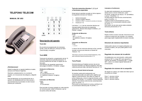
Descripción del aparatoTecla SetEs una tecla de programación de memorias, sonido, modo de selección y tiempo de Flash (Tecla Plustel) u horquilleo.Tecla MEMTecla para la activación y programación de las 10 memorias. Esta tecla le permite almacenar 10 números telefónicos de hasta 16 dígitos de uso frecuente.Para efectuar las siguientes operaciones descuelgue el teléfono. Al finalizar, cuelgue.Grabación de Memorias Pulse:. SET + MEM. N ° de memoria de 0 a 9. N ° telefónico (máximo 16 dígitos) . SETLlamando con Memorias Pulse: . MEM. N ° de memoriaPara recordar el número grabado en cada posición de memoria puede utilizar el Directorio, que se encuentra arriba del teclado.TELEFONO TELECOMMANUAL DE USOTecla de memorias directas 1, 2, 3 y 4 o funciones especialesEstas teclas le permiten acceder en forma rápida a los siguientes servicios de Telecom:1 Señal de llamada*.2 Acceso a tarjeta Telecom.3 Acceso a CALL* (contestación automática de llamadas).4 Acceso al 112.Las teclas 1, 2 y 3 de las memorias directas son reprogramables efectuando las siguientesoperaciones. Siempre descuelgue el teléfono, y al finalizar, cuelgue.Grabación de Memorias Pulse: . SET + 1, 2, ó 3 . N ° telefónico (máximo 16 dígitos) . SETLlamando con Memorias Pulse: . 1, 2 ó 3La tecla 4 de las memorias directas es fija y permite acceder al servicio de Atención al Cliente de Telecom, 112.*Para hacer uso de los servicios Señal de llamada y CALL debe solicitarlos llamando previamente al 112.Tecla PlustelEsta tecla tiene por finalidad accionar dos de los servicios PLUSTEL de Telecom Argentina. Para ello, usted previamente debe solicitarlos llamando al 112.Servicios Plustel Señal de llamadaSi mientras usted está manteniendo unacomunicación recibe una señal corta, significa que alguien lo está llamando. Para dejar en espera al primer interlocutor y tomar la segunda llamada, pulse las teclas: PLUSTEL + 2, o la tecla 1 de las memorias directas. Para alternar entre las dos conversaciones, pulse: PLUSTEL + 2.Para cortar la comunicación en curso y continuar con la conversación retenida pulse: PLUSTEL + 1.Llamada en ConferenciaSi usted está manteniendo una conversación y desea incluir un tercer interlocutor, pulse:PLUSTEL (recibe tono de discar) + N ° del teléfono a incluir + PLUSTEL + 3.Si quiere alternar entre las dos conversaciones, pulse: PLUSTEL + 2.Si desea cortar la comunicación en curso y continuar con la conversación retenida, pulse: PLUSTEL + 1.Para hacer uso de este servicio debe solicitarlo llamando previamente al 112.Tecla rellamaRepite el último número marcado. Esta tecla es útil cuando se recibe tono de ocupado o no contesta, para luego repetir rápidamente el número marcado.Directorio de números importantesUsted podrá colocar en el papel preimpreso sus números usuales y los que pueda grabar en las memorias .Regulador de volumen de la audiciónAl establecerse una comunicación, usted podrá presionar SET 3 y luego SET para aumentar el volumen de audición. Al presionar SET 1 y luego SET, vuelve a su estado original finalizando la comunicación.Regulador de volumen de la campanillaSe regula en 3 pasos, por medio de la llave que se encuentra en la base:Paso 1: volumen mínimo Paso 2: volumen medio Paso 3: volumen máximo¡Felicitaciones!Usted ha adquirido un aparato telefónico modelo exclusivo de Telecom Argentina.Diseñado cuidadosamente, es un productodurable, con innovaciones tecnológicas y elegante estilo.Para familiarizarse con las prestaciones de su aparato, lea detalladamente las instrucciones y recomendaciones enumeradas en este manual. Gracias por su elección.Base del aparato:1. Zócalo conector cable de líneaUna vez insertado el cable en el zócalo, puede sacarse hacia delante o hacia atrás, a través de las guías en la base del aparato.2. Zócalo conector cable del microteléfono Una vez insertado el cable en el zócalo, debe sacarse hacia el lateral, a través de la guía en la base del aparato.GARANTIATelecom Argentina Stet-France Telecom S.A.(Telecom) garantiza el correcto funcionamiento del terminal entregado, por doce meses contados a partir de la fecha de venta, período durante el cual reparará o en su caso reemplazará por otro de similares características, sin cargo alguno para el Cliente, el terminal o aquella parte del mismo que no obstante su normal utilización, resultaradeficiente en razón de material vicioso o defectos de fabricación.Quedan expresamente excluidas de la cobertura las fallas y/o roturas del terminal, atribuibles a su incorrecta instalación, inadecuada manipulación, quita de componentes, o las debidas a cualquier causa ajena al producto y todo supuesto de caso fortuito o fuerza mayor. Esta garantía se extinguirá anticipada y automáticamente si Telecomcomprobara a su único criterio, que el terminal fue desarmado y/o reparado por personas no autorizadas.Las reparaciones y/o reemplazos de aparatos y/o piezas realizadas en cumplimiento de la garantía no interrumpirán ni extenderán de modo alguno el período de vigencia de la misma.Para hacer uso de la garantía, además de éste documento es imprescindible presentar elrespectivo terminal con su identificación y número de serie original y sin enmiendas así como el original de recibo o factura correspondiente. Para realizar consultas, llame sin cargo al 112.Nombre y Apellido: ……………….........…………… Dirección: ……………………….........……………… N° de serie del aparato: …….........………………… N° de teléfono: …………………..….......……………Regulador de melodías de la campanillaAntes de realizar cualquiera de estas operaciones, descuelgue el teléfono. Al finalizar, cuelgue.Tecla silenciarPermite cancelar la recepción y emisión de la voz durante una conversación.Teclas especialesLa mayoría de las centrales públicas y privadas modernas (con selección por multifrecuencias) ofrecen facilidades adicionales que pueden activarse pulsando la tecla Plustel, la teclaasterisco (*) o la tecla numeral (#). Para mayores detalles llame al 112.Cambio en el modo de selecciónEl uso de esta función está reservado al técnico instalador de su teléfono. Antes de realizarcualquiera de estas operaciones, descuelgue el teléfono. Al finalizar, cuelgue.Es recomendable utilizar el discado por tonos.SET SET SET 6 5 4 SET SET SET Pulse: Pulse: Pulse: Sonido 3 Sonido 2 Sonido 1 Sonido SET SET 1 1 8 7 SET SET Pulse: Pulse: Discado por pulso Discado por tonos Conectando su aparato telefónico1. Enchufe la ficha terminal del cordón del microteléfono dentro del mismo.2. Enchufe la ficha terminal del cordón del microteléfono en la base del aparato.3. Enchufe la ficha terminal del cordón de entrada de línea dentro de la base del aparato.4. Enchufe la ficha terminal del cordón de entrada de línea en el conector ubicado en la pared.5. Controle el nivel de volumen del tono decampanilla de llamada marcando 115 y cuelgue. 6. Para fijar parámetros por defecto (volumen del tono de llamada alto, sonido 1, discado por tonos y velocidad de FLASH de 300 ms.), descuelgue y pulse: SET + * + SET. Cuelgue. Para fijar los mismos parámetros y borrar la memoria, descuelgue y pulse: SET + # + SET.Consejos útilesLa siguiente información le será útil para que su aparato telefónico funcione y luzca correctamente durante la vida útil del mismo. Lea detalladamente y conserve este manual y certificado de garantía para su futura consulta:No instale o sitúe su aparato cerca de fuentes de calor o dispositivos que puedan producir ruido eléctrico (Ej. Motores, lámparas fluorescentes). No exponga su aparato en forma directa a los rayos solares.Evite caídas de su aparato telefónico y no lo golpee. Para limpiar su aparato telefónico proceda solamente con un trapo humedecido con agua (recuerde desconectar la ficha de conexión de la ficha de la pared).Nunca utilice agentes químicos o abrasivos que puedan dañar el acabado superficial del aparato. No lo sumerja y evite que chorros de agua se introduzcan en su aparato, pues lo dañarán seriamente.No obstruya las aberturas provistas en el aparato para su ventilación.Coloque siempre su aparato sobre una superficie segura y regular.No enchufe ni introduzca las fichas terminales de los cordones de conexión en otras fuentes de poder que no sean las específicas de la línea de servicio telefónico.No instale su aparato donde los cordones de conexión puedan ser afectados por el paso de personas sobre ellos.No deposite sobre el teléfono lámparas eléctricas, velas, cigarrillos encendidos, etc.En caso de detectar pérdidas de gas, evite utilizar el aparato hasta ventilar correctamente el ambiente afectado.No modifique o instale los cables de conexión de su aparato durante una tormenta eléctrica. Siempre consulte a su Centro de Reparaciones (disque 114) en los siguientes casos: Si el equipo se encuentra dentro del período de garantía.Cuando los cordones o fichas de conexión estén dañados.Si el aparato fue expuesto a líquidos (agua, lluvia, café, etc.).Si el aparto no funciona correctamente, de ser posible desconéctelo y pruebe con otro aparato, o conéctelo en otra boca de la línea para comprobar si la falla está en el mismo.Si con esta verificación usted comprueba que la dificultad está en su aparato, controle la lista de solución de desperfectos sencillos enumerados en este manual. Si no encontró solución al mismo, consulte al Servicio de Reparaciones llamando al 114.No proceda nunca a la apertura, desarme o reemplazo de piezas del aparato.Lista de chequeo de ServiceProblema: 1) No hay tono de discar.Solución: Controle los cordones. ¿Están correctamente conectados? ¿Están dañados? Conecte bien cada cordón. Solicite reemplazo.2) La campanilla no funciona. Solución: Verifique correctamente el procedimiento de control de llave de volumen de la campanilla. Verifique que los aparatos conectados sobre la misma línea no excedan la cantidad de tres, aconsejada por Telecom Argentina. ¿Estáncorrectamente conectados?Verifique el regulador de campanilla.。


Solarproducts2Solar fusesREDindicates NEW information ContentsDescription Page Fuse holder and blockselection guide 2-2Volt F uses Size 600Vdc . . . . . . . . . . .PVM. . . . . 13/32˝ x 1 1/2˝. . . . . . . . . 2-4600Vac /300Vdc . . . .PVCF. . . . .CUBEFuse™. . . . . . . . .. 2-5600Vac/dc. . . . . .. . .PVS-R. . . .RK5. . . . . . . . . . . . . . . . . 2-71000Vdc . . . . . . . .. .PV. . . . . . .10x38mm . . . . . .. . . . . . .2-81000Vdc . . . . . . . .. .HPV. . . . . .10x38mm(in-line assembly). . . . . . . .2-91000/1100Vdc. . . .. .PV. . . . . . .14x51mm . . . . . . . . . . .2-101000Vdc . . . . . . . . . .NH. . . . . . .NH Sizes 1, 2, 3. . . . . . . 2-111000Vdc . . . . . . . . . .XL PV. . . . XL Size 01, 1, 2, 3. . .. . .2-121300/1500Vdc . . . .. .PV. . . . . . .14x65mm. . . . . . . . . . . .2-151200/1500Vdc . . . .. .XL PV. . . . XL Size 01, 1, 2, 3. . . . .2-162Solar fuses Holders and blocks for photovoltaic fuses 600 Volts Fuses Volts Page Midget. . . . . . . . . . . . . .PVM. . . . . . . . . . .600V. . . . . . . . . .2-4CF. . . . . . . . . . . . . . . . .CFPV. . . . . . . . . .600V. . . . . . . . . .2-5RK5. . . . . . . . . . . . . . . .PVS-R . . . . . . . . .600V. . . . . . . . . .2-7Holders •TCFH CUBEFuse holder, panel/DIN-Rail mount . . . . . . . . . . . . .1-16•CHM DIN-Rail mount holders . . . . . . . . . . . . . . . . . . . . . . . . . .9-2•HEB in-line holders. . . . . . . . . . . . . . . . . . . . . . . . . . . . . . . . . .9-46Blocks •Modular knifeblade fuse blocks 250/600V, panel mount . . . . . . . 9-17•RM600 RK5 open fuse blocks . . . . . . . . . . . . . . . . . . . . . . . . . .9-24•BMM midget open fuse blocks. . . . . . . . . . . . . . . . . . . . . . . . . .9-32BMM HEB TCFHR600Modular knifeblade1000 Volts Fuses Volts Page 10x38mm . . . . . . . . . . .PV-_A10. . . . . . . .1000V . . . . . . . . .2-814x51mm . . . . . . . . . . .PV-_A14. . . . . . . .1000/1100V. . . . .2-10NH Sizes 1, 2 and 3 . . . . PV-_ANH . . . . . . .1000V . . . . . . . . .2-1101XL . . . . . . . . . . . . . . .PV-_A-01XL . . . . .1000V . . . . . . . . .2-121XL . . . . . . . . . . . . . . . .PV-_A-1XL . . . . . .1000V . . . . . . . . .2-122XL . . . . . . . . . . . . . . . .PV-_A-2XL . . . . . .1000V . . . . . . . . .2-123L . . . . . . . . . . . . . . . . .PV-_A-3L . . . . . . .1000V . . . . . . . . .2-12Holders •CHPV 10x38 DIN-Rail mount holders . . . . . . . . . . . . . . . . . . . .9-2•CH14 14x51 DIN-Rail mount holders. . . . . . . . . . . . . . . . . . . . .9-2•HEB* 10x38 in-line holders. . . . . . . . . . . . . . . . . . . . . . . . . . . .9-46•HPV in-line holder assembly. . . . . . . . . . . . . . . . . . . . . . . . . . . .9-46* Self certified to 1000Vdc.Blocks•SB1XL-S 01XL and 1XL blocks . . . . . . . . . . . . . . . . . . . . . . . . .2-12•SB2XL-S 2XL blocks. . . . . . . . . . . . . . . . . . . . . . . . . . . . . . . . .2-12•SB3L-S 3L blocks. . . . . . . . . . . . . . . . . . . . . . . . . . . . . . . . . . .2-12•SD1-D-PV**. . . . . . . . . . . . . . . . . . . . . . . . . . . . . . . . . . . . . . .2-11•SD2-D-PV**. . . . . . . . . . . . . . . . . . . . . . . . . . . . . . . . . . . . . . .2-11•SD3-D-PV**. . . . . . . . . . . . . . . . . . . . . . . . . . . . . . . . . . . . . . . 2-11** IEC only to 1000Vdc.CHPV CHM CH14HEB SD1-D-PV SB2XL-S SB3L-S HPVSB1XL-SSolarproducts2Solar fuses Holders and blocks for photovoltaic fuses SB2XL-S SB3L-S 1500 Volts Fuses Volts Page 01XL . . . . . . . . . . .PV-_A-01XL-15 . . . .1500V . . . . . . . . .2-161XL . . . . . . . . . . . .PV-_A-1XL-15 . . . . .1500V . . . . . . . . .2-162XL . . . . . . . . . . . .PV-_A-2XL-15 . . . . .1500V . . . . . . . . .2-163L . . . . . . . . . . . . .PV-_A-3L-15 . . . . . .1500V . . . . . . . . . 2-1614x65mm PV-_A14*. . . . . . . . .1300/1500V. . . . .2-15Blocks•SB1XL-S** 01XL and 1XL blocks . . . . . . . . . . . . . . . . . . . . . .2-16•SB2XL-S** 2XL blocks. . . . . . . . . . . . . . . . . . . . . . . . . . . . . .2-16•SB3L-S** 3L blocks . . . . . . . . . . . . . . . . . . . . . . . . . . . . . . . .2-16*Available with tags for bolt mounting or 10mm fixings for mounting in modular blocks for 10mm diameter fuses.** IEC only to 1500Vdc.SB1XL-S2Solar fuses13/32˝ x 1 1/2˝ Midget PV fusesRecommended fuse holders and blocks for the PVM fuse Specifications:Description:fast-acting 600Vdc Midget fuses specificallydesigned to protect solor power systems inextreme ambient temperature, high cyclingand low level fault current conditions (reversecurrent, multi-array fault).Dimensions:13⁄32˝ x 1 1⁄2˝(10.3 x 38.1mm).Ratings:Volts— 600Vdc to UL 2579Amps— 4-30AIR— 50kA DC (4-30A)Agency information:UL Listed 2579, Guide JFGA, FileE335324, CSA Component Certified C22.2. RoHS compliant.Features and benefits:•Specifically designed to protect solar power systems inextreme ambient temperature per UL 2579 listed•Capable of withstanding high cycling and low level faultcurrent conditionsTypical applications:•Solar combiner boxes•Solar string protectorsCatalog numbers (amps)PVM-4PVM-7PVM-10PVM-20PVM-5PVM-8PVM-12PVM-25PVM-6PVM-9PVM-15PVM-30PVMData Sheet: 2153Catalog Amp Power loss (watts)number rating n 1.0 x I nPVM-1010 1.0 1.9PVM-1515 1.0 1.7PVM-3030 1.6 2.9I n= Rated currentPower loss (watts)Dimensions - (mm)11CURRENT IN AMPS.01.1110100AMP5AAAAAA1,TIMEINSECONDSSolar products2Solar fusesPhotovoltaic CUBEFuse™PVCF 600VData Sheet: 2155Carton quantity and weightAmp Carton Weight per cartonrating qty.lbs kgPVCF-35-60A12 1.420.65PVCF-70-100A6 1.740.79Catalog symbol:PVCF_RNFast-acting fuse:6 minutes maximum clearing time at 200%rated current for 30 to 60A fuse8 minutes maximum clearing time at 200%rated current for 70 to 100A fuseRatings:Volts— 600VdcAmps— 35-100AIR— 50kA DC (UL and CSA)Agency information:•UL 2579 Listed Fuse: Guide JFGA, File E335324•CSA Certified Fuse: Class C22.2•RoHS compliantOther ratings/specifications:Watts loss at rated current:PVCF35RN: 5.45WPVCF60RN: 7.27WPVCF100RN: 11.50WOperating and storage temperature range:-40 to 90°CMaterial specifications:• Case: glass filled PES (Polyethersulfone)• Terminals: copper alloy• Terminal plating: electroless tinFeatures and product benefits:•Maximize uptime and reliability using fuses designed and list-Low Voltage Fuses - Fuses for PhotovoltaicSystems.•Minimize chances of equipment failure and personnel injurywhen using full range fuses having the industry’s fastestresponse time to low-magnitude faults.•Maximize return on investment with fuses proven towithstand harsh temperatures.•Minimize design time, operating outage time andchanging enviromental conditions.•Simplify compatibility with readily available industrystandard Class CF holders.•Temperature derating: designed to maximize rated capacity inelevated environmental temperatures.•Overload protection: proven to clear faults faster than the ULrequirement.•Power loss: minimal energy consumption leading to increasedefficiency.Recommended fuse holders for Class CF fuses•2Solar fuses Photovoltaic CUBEFuse™ Data Sheet: 2155 Time-current characteristic curves–average melt 100A60A40A 50A 35A2Solar fusesLimitron™ fast-acting fusesData Sheet: 4203PVS-R(600Vac/dc) Class RK5Recommended fuse holders and blocks for Class RK5 fuses•See page 1-32Solar fuses 10x38mm photovoltaic fuses Description:A range 10x38mm, 1000Vdc PV fuses for the protection and isolation of photovoltaic strings. The fuses arespecifically designed for use in PV systems with extreme ambient temperature, high cycling and low fault current conditions (reverse current, multi-array fault) string arrays.flexibility.Basic fuse size:•10x38mm Catalog symbols:1-20A*—PV-(amp)A10F (cylindrical)—PV-(amp)A10-T (bolt mounting)—PV-(amp)A10-1P (single PCB tab)—PV-(amp)A10-2P (dual PCB tab)—PV-(amp)10F-CT (in-line, crimp terminals)25-30A**—PV10M-(amp) (cylindrical)—PV10M-(amp)-CT (in-line, crimp terminals)*Ceramic tube construction.**Melamine tube construction.Time constant:•1-3ms PV Fuse coordination:With thin film cells and 4”, 5” and 6” crystalline silicon cells Agency information:•UL Listed to 2579*, Guide JFGA, File E335324•IEC 60269-6 (gPV)•CSA File 53787, Class 1422-30 (1-15A), 20-30A Pending •CCC (1-20A) (25-30A pending)•RoHS Compliant *Except crimp terminal version that is UL Recognized to UL 2579, Guide JFGA2, File E335324.Features and benefits:•Meets UL and IEC photovoltaic standards for global acceptance •Low watts loss performance for energy efficiency •Low temperature rise performance for more precise sizing •In-line crimp terminal version is easy to apply in wire harness construction Typical applications:•Combiner boxes •Inverters •PV wire harnesses Recommended fuse blocks, holders and fuseclips:Part number Description Data Sheet #BPVM_10265with optional cover CHPV_Lit # 3185with optional open fuse indication 1A3400-09PCB fuseclip 2131HPV-DV-_AIn-line fuse holder assembly 2157Data Sheet: 1012110x38mm fuses — 1000Vdc, 1-30A Catalog numbers (amp)/electrical characteristics:Rated I 2t (A 2s)Cylindrical Bolt PCB fixing PCB fixing Rated volts Interrupting Pre-Total @Watts loss ferrule fixing single pin double pin crimp terminal amps Vdc rating arcing rated volts 0.8I n I n PV-1A10F PV-1A10-T PV-1A10-1P PV-1A10-2P PV-1A10F-CT 1100050kA 0.150.40.8 1.5PV-2A10F PV-2A10-T PV-2A10-1P PV-2A10-2P PV-2A10F-CT 2100050kA 1.2 3.40.6 1.0PV-3A10F PV-3A10-T PV-3A10-1P PV-3A10-2P PV-3A10F-CT 3100050kA 4110.8 1.3PV-3-5A10F PV-3-5A10-T PV-3-5A10-1P PV-3-5A10-2P PV-3-5A10F-CT 3.5100050kA 6.6180.9 1.4PV-4A10F PV-4A10-T PV-4A10-1P PV-4A10-2P PV-4A10F-CT 4100050kA 9.526 1.0 1.5PV-5A10F PV-5A10-T PV-5A10-1P PV-5A10-2P PV-5A10F-CT 5100050kA 1950 1.0 1.6PV-6A10F PV-6A10-T PV-6A10-1P PV-6A10-2P PV-6A10F-CT 6100050kA 3090 1.1 1.8PV-8A10F PV-8A10-T PV-8A10-1P PV-8A10-2P PV-8A10F-CT 8100050kA 332 1.2 2.1PV-10A10F PV-10A10-T PV-10A10-1P PV-10A10-2P PV-10A10F-CT 10100050kA 770 1.2 2.3PV-12A10F PV-12A10-T PV-12A10-1P PV-12A10-2P PV-12A10F-CT 12100050kA 12120 1.5 2.7PV-15A10F PV-15A10-T PV-15A10-1P PV-15A10-2P PV-15A10F-CT 15100050kA 22220 1.7 2.9PV-20A10F PV-20A10-T PV-20A10-1P PV-20A10-2P PV-20A10F-CT 20100050kA 34350 2.1 3.6PV10M-25————25100020kA 3251860* 1.7 2.9PV10M-30————30100020kA 5363360* 1.7 3.3*Total I 2************************************.Solarproducts2Solar fuses 10x38mm photovoltaic in-line assembly Data Sheet: 2157HPV — 1000Vdc Catalog symbol:HPV-DV-(amp)ADescription:Single-pole, non-serviceable photovoltaic in-line fuse holderand fuse assembly in an IP67 dust tight and temporary water immersion resistant insulating boot for use in photovoltaic wire harnesses.Ratings — 1000Vdc Amps — 1-20AIR — 33kA Agency information • UL Listed to 4248-1 and 4248-18. File # E 348242• CSA Component Acceptance, Class 6225 30, File # 47235• CE, RoHS Compliant, IP20 Finger-safe, IP67Conductors • 75°C/90°C Cu Stranded 12-10AWG PV wire T erminals • Crimp connection for single, stranded 12-10AWG PV conductor Boot material • UL 5VA flammability resistant rated elastomer. • UV resistant to UL F1 suitable for outdoor use.Operating and storage temperature range • -40°C to +90°C PackagingBulk packed in cartons, 180 fuse assemblies per carton. Cartonweight 19.3 Lbs (8.7543kg).Fuse assemblies poly bagged with PV fuse element, two insulating boots (for lineside and loadside), and one pressure to the wire harness.Catalog numbers (amps) and fuse elements*HPV catalog number 10x38mmPV fuse part number Amps HPV-DV-1A PV-1A10F-CT 1HPV-DV-2A PV-2A10F-CT 2HPV-DV-2.5A PV-2.5A10F-CT 2.5HPV-DV-3A PV-3A10F-CT 3HPV-DV-3.5APV-3.5A10F-CT 3.5HPV-DV-4A PV-4A10F-CT 4HPV-DV-5APV-5A10F-CT5HPV-DV-6A PV-6A10F-CT 6HPV-DV-8A PV-8A10F-CT 8HPV-DV-10A PV-10A10F-CT 10HPV-DV-12A PV-12A10F-CT 12HPV-DV-15A PV-15A10F-CT 15HPV-DV-20A PV-20A10F-CT 20* For fuse specifications and derating curves see data sheet no. 10121 at/DatasheetsEle.Recommended tools • Sta-Kon™ terminal crimping tool, catalog # ERG4002• Multi-Contact assembly tool, catalog # PV-RWZ with PV-KOI+II and PV-KOIII tapered spindles2Solar fuses 14x51mm photovoltaic fuses Time-current characteristic curves—average melt Dimensions - mmData Sheet: 720132Available current (amps), DC-time constant 1-3ms Recommended fuse holders and blocks for 14x51mm fuses •See page 2-2Features and benefits:•Specifically designed to provide fast-acting protection under low fault current conditions associated with PV systems •High DC voltage rating •Demonstrated performance in extreme temperature cycling conditions Typical applications:•Combiner boxes •Inverters Recommended fuse holder:CH141B-PV DIN-Rail modular fuse holder See data sheet # 720148 for more information.14x51mm fuses — 1000/1100Vdc, 15-32A2-11Solar products2Solar fusesNH photovoltaic fusesBUSSMANN SERIES FULL LINE CATALOG1007—July 2015 /bussmannseries Description:A range of 1000Vdc NH size Photovoltaic (PV) fusesspecifically designed for protecting and isolating arraycombiners/re-combiners, disconnects and inverters.Ratings:Volts— 1000VdcAmps— 32-400AIR— 50kAAgency information:•UL Listed, Guide JFGA, File E335324.Photovoltaic to UL 2579•IEC 60269-6 gPV•CSA Class 1422-30, File 53787 (32-160A)•UL Listed, IEC gPV, CSA, CCC Pending, RoHS compliantCatalog numbers/electrical characteristics:Data Sheet: 720133Features and benefits:•Compact size saves panel space and extends designflexibility•Bolt-on versions have common hole centers forstandardizing busbar designs across 63-400 amp range•Low power loss for greater efficiency and loweroperating temperature•Global agency standards simplifies designconsiderations for worldwide markets•Dual indication feature and optional microswitchesmake system monitoring easierTypical applications:•Recombiner boxes•InvertersRecommended fuse blocks*:Fuse size Fuse blockNH1SD1-D-PVNH2SD2-D-PVNH3SD3-D-PVSee data sheet # 720149 for more information.Optional microswitches*:Tab size/number mm (inch)Connection Volts Amps170H0236250/6.3 (1⁄4)Quick connect2502170H0238110/2.8 (0.11)Quick connect2502BVL50187/4.8 (3⁄16)Quick connect2506 NH fuses — 1000Vdc, NH1, 2, 3, 32-400A*For use with bladed version.FusesizeCurrentrating(amps)Energy integralsI2t (A2S)Watts lossPart numberPre-arcingT otal at1000V0.8InInPV-32ANH1NH1328072048PV-40ANH1NH140185167059PV-50ANH1NH1504003600611PV-63ANH1NH1634704300612PV-80ANH1NH1806405760815PV-100ANH1NH1100130011,700816PV-125ANH1NH1125260023,400917PV-160ANH1NH1160520046,8001427PV-200ANH1NH120010,20082,0001325PV-250ANH2NH225017,000136,0001938PV-300ANH3NH330032,000260,0002440PV-315ANH3NH331532,000260,0002644PV-350ANH3NH335044,500370,0002745PV-355ANH3NH335544,500370,0002846PV-400ANH3NH340067,500550,0003050Blade without bolt-holesSee data sheet No. 720133 for complete details.Part numberwith bolt holesFusesizeCurrentrating(amps)Energy integralsI2t (A2S)Watts lossPre-arcingT otal at1000V0.8InInPV-63ANH1-B NH1634704300612PV-80ANH1-B NH1806405760815PV-100ANH1-B NH1100130011,700816PV-125ANH1-B NH1125260023,400917PV-160ANH1-B NH1160520046,8001427PV-200ANH1-B NH120010,20082,0001325PV-250ANH2-B NH225017,000136,0001938PV-315ANH3-B NH331532,000260,0002644PV-355ANH3-B NH335538,000310,0002948PV-400ANH3-B NH340061,000490,0003250See data sheet No. 720133 for complete details.Blade with bolt-holesRequest Info2-12BUSSMANN SERIES FULL LINE CATALOG 1007—July 2015 /bussmannseries 2Solar fuses1000Vdc XL photovoltaic fuses Data Sheet: 10201Description:protecting and isolating photovoltaic array combiners and disconnects. These fuses are capable of interrupting low overcurrents associated with faulted PV systems (reverse microswitches for use in monitoring systems.Catalog symbols:Blade — PV-(amp)A(size)XL Bolt-In — PV-(amp)A(size)XL-B Agency information:•UL 2579, Guide JFGA, File E335324•IEC 60269-6•CSA Class 1422-30, File 53787•RoHS Compliant Features and benefits:•Specifically designed to provide fast-acting protection under low fault current conditions associated with PV systems •High DC voltage rating •Variety of mounting options for flexibility •Demonstrated performance in extreme temperature cycling conditions Typical applications:•Recombiner boxes •InvertersRecommended fuse holders:Fuse size Part number Description 01XL SB1XL-S 1-pole block 1XL SB1XL-S 1-pole block 2XL SB2XL-S 1-pole block 3L SB3L-S 1-pole block See data sheet # 10066 for more information.Optional microswitches:Blade — 170H0235 or 170H0237 for size 01XL— 170H0236 or 170H0238 for sizes 1XL, 2XL and 3LBolt-in — 170H0069 for all sizes XL fuses — 1000Vdc, XL01, 1, 2, 3, 63-630A Catalog numbers (amp)/electrical characteristics:Rated I 2t (A 2s)Rated volts Interrupting Total @Watts loss Fuse size Bladed version Bolted version amps Vdc rating Pre-arcing rated volts 0.8I n I n PV-63A-01XL PV-63A-01XL-B 63100050kA 26019001324PV-80A-01XL PV-80A-01XL-B 80100050kA 4903600172901PV-100A-01XL PV-100A-01XL-B 100100050kA 87063001832PV-125A-01XL PV-125A-01XL-B 125100050kA 193013,9002040PV-160A-01XL PV-160A-01XL-B 160100050kA 390028,10022441PV-200A-1XL PV-200A-1XL-B 200100033kA 940027,2603160PV-160A-2XL PV-160A-2XL-B 160100033kA 278021,0002544PV-200A-2XL PV-200A-2XL-B 200100033kA 495037,00028502PV-250A-2XL PV-250A-2XL-B 250100033kA 945070,0003460PV-315A-2XL PV-315A-2XL-B 315100033kA 16,600123,0004066PV-350A-2XL PV-350A-2XL-B 350100033kA 26,000192,0004268PV-355A-2XL PV-355A-2XL-B 355100033kA 26,000192,0004268PV-350A-3L PV-350A-3L-B 350100050kA 31,000161,2004065PV-400A-3L PV-400A-3L-B 400100050kA 44,500231,40048823PV-500A-3L PV-500A-3L-B 500100050kA 85,000442,0005085PV-600A-3L PV-600A-3L-B 600100050kA 137,000712,40080108PV-630A-3L*PV-630A-3L-B*630*100050kA 137,000712,40092118*630A thermally rated to UL only.Request Info2-132Solar fuses1000Vdc XL photovoltaic fuses for solar ap plications BUSSMANN SERIES FUL L LINE CATALOG 1007—July 2015 /bussmannseries 2XL blade sizeDimensions - mm (n ot to scale)3L blade size3L bolt size01XL blade size 01XL bolt sizeData Sheet: 7201342XL bolt size Request Info2-14BUSSMANN SERIES FULL LINE CATALOG 1007—July 2015 /bussmannseries 2Solar fuses 1000Vdc XL photovoltaic fuses for solar applications Data Sheet: 720134100100010000160A 125A 100A 200A 0.010.11100001000100101P r e -a r c i n g T i m e (s )63A 80A Time-current curves for 01XL and 1XL Available current (amps), DC-time constant 1-3ms Time-current curves for 2XLAvailable current (amps), DC-time constant 1-3ms Time-current curves for 3L Available current (amps), DC-time constant 1-3ms2-152Solar fuses 14x65mm photovoltaic fuses BUSSMANN SERIES FULL LINE CATALOG 1007—July 2015 /bussmannseries 14x65mm fuses — 1300/1500Vdc, 2.25-32A Features and benefits:•Specifically designed to provide fast-acting protection under low fault current conditions associated with PV systems •Variety of mounting options for flexibility •Fuses meet UL and IEC photovoltaic standards for global product acceptance Data Sheet: 1172Request Info2-16BUSSMANN SERIES FULL LINE CATALOG 1007—July 2015 /bussmannseries 2Solar fuses 1500Vdc XL photovoltaic fuses Data Sheet: 10201Description:protecting and isolating photovoltaic array combiners and disconnects. These fuses are capable of interrupting low microswitches for use in monitoring systems.Catalog symbols:Blade — PV-(amp)A(size)XL-15Bolt-In — PV-(amp)A(size)XL-B-15Agency information:•UL Listed, Guide JFGA, File E335324. Photovoltaic to UL 2579•IEC 60269-6 gPV •CSA Class 1422-30, File 53787•RoHS compliant Features and benefits:•Specifically designed to provide fast-acting protection PV systems •Variety of mounting options for flexibility Typical applications:•Recombiner boxes •InvertersRecommended fuse holders:Fuse size Part number Description 01XL SB1XL-S 1-pole block 1XL SB1XL-S 1-pole block 2XL SB2XL-S 1-pole block 3L SB3L-S 1-pole block See data sheet # 10066 for more information.Optional microswitches:Blade — 170H0235 or 170H0237 for size 01XL— 170H0236 or 170H0238 for sizes 1XL, 2XL & 3LBolt-in — 170H0069 for all sizes XL PV fuses — 1500Vdc, XL01, 1, 2, 3, 50-400A Catalog numbers (amp)/electrical characteristics:Rated I 2t (A 2s)Rated volts InterruptingTotal @Watts loss Fuse size Bladed version Bolted version amps Vdc rating Pre-arcing rated volts 0.8I n I n PV-50A-01XL-15PV-50A-01XL-B-1550150030kA 7510001425PV-63A-01XL-15PV-63A-01XL-B-1563150030kA 3622250152601PV-80A-01XL-15PV-80A-01XL-B-1580150030kA 56533001935PV-100A-01XL-15PV-100A-01XL-B-151********kA 110066002240PV-125A-01XL-15PV-125A-01XL-B-151********kA 220010,5002342PV-160A-01XL-12PV-160A-01XL-B-12160120030kA 500024,0002652PV-100A-1XL-15PV-100A-1XL-B-151********kA 1250600024431PV-125A-1XL-15PV-125A-1XL-B-151********kA 195093602552PV-160A-1XL-15PV-160A-1XL-B-151********kA 420020,1603058PV-200A-1XL-15PV-200A-1XL-B-152********kA 940045,1203161PV-125A-2XL-15PV-125A-2XL-B-151********kA 220015,00025442PV-160A-2XL-15PV-160A-2XL-B-151********kA 500032,0002948PV-200A-2XL-15PV-200A-2XL-B-152********kA 880051,0003257PV-250A-2XL-15PV-250A-2XL-B-152********kA 16,60085,0004070PV-250A-3L-15PV-250A-3L-B-152********kA 22,30092,00032503PV-315A-3L-15PV-315A-3L-B-153********kA 38,000160,0003666PV-355A-3L-15PV-355A-3L-B-153********kA 44,500184,0004480PV-400A-3L-15PV-400A-3L-B-15400150030kA58,000240,0004991Request Info2-17Solar products2Solar fuses1500Vdc XL photovoltaic fusesBUSSMANN SERIES FULL LINE CATALOG1007—July 2015 /bussmannseriesDimensions - mm (not to scale)Bladed - size 01XL, 1XL, 2XL and 3L1XL blade size1XL bolt size2XL blade size3L blade size3L bolt size01XL blade size01XL bolt sizeData Sheet: 7201342XL bolt sizeRequest Info2-18BUSSMANN SERIES FULL LINE CATALOG1007—July 2015 /bussmannseries2Solar fuses1500Vdc XL photovoltaic fusesData Sheet: 720134Time-current curves for 01XL - 1500VdcAvailable current (amps), DC-time constant 1-3msTime-current curves for 1XL - 1500VdcAvailable current (amps), DC-time constant 1-3ms Time-current curves for 2XL - 1500VdcAvailable current (amps), DC-time constant 1-3msTime-current curves for 3L - 1500VdcAvailable current (amps), DC-time constant 1-3msRequest Info。

意大利红酒产品展示——青岛圣德隆国际贸易有限责任公司
巴洛卡梅洛干红葡萄酒
此款酒具有浓郁的果香气味
和柔和的口感,具有多种的水果香
气,余味复杂且悠长。
与各种红肉,
禽肉及鱼类相得益彰。
配料:葡萄汁、微量二氧化硫
葡萄品种:梅洛
酒精度:12%vol
级别:IGT
葡萄年份:2010
产品类型:干型
装瓶日期:2011年10月5日
保质期:10年
原产国:意大利
产区:意大利威尼托
生产商:意大利伊洛斯公司
储存方式:10-20℃卧放于通风避
光无异味处
净含量:750ml
圣地安梅洛葡萄葡萄酒
此款酒具有浓郁的果香气味和柔和的口感,具有多种的水果香气,余味复杂且悠长。
与各种红肉,禽肉及鱼类相得益彰。
配料:葡萄汁、微量二氧化硫
葡萄品种:梅洛
酒精度:11.5%vol
级别:IGT
葡萄年份:2010
产品类型:干型
装瓶日期:2011年10月5日
保质期:10年
原产国:意大利
产区:意大利威尼托
生产商:意大利伊洛斯公司
储存方式:10-20℃卧放于通风避光无异味处
净含量:750ml。

Read these instructions before using your product.Note for Spanish speakers/Nota para hispanohablantes: Para obtener instrucciones de configuración en español, consulte la Guía de instalación en /support/wfm5299sp(requiere una conexión a Internet).French controlpanel stickersWarning: The product is heavy and should be lifted and moved by two people.1 Remove all protective materials from the product.2 R31 CCaution: Do not connect to your computer yet.2 T3 S elect your language and time on the LCD screen.Note: You can change these settings later using the product’s control panel. For more information, see the online User’s Guide .I nstall ink supply unit(ink pack)Note:• T he product is designed for use with Epson ® ink packs only, notthird-party ink.• T he ink pack included with the product is designed for product setup and not for resale.• A fter some ink is used for charging, the rest is available for printing.3 R emove and discard the protective piece from the inkpack tray.4 S hake the ink pack 10 times, then remove it from thepackaging.Note: Do not touch the green chip on the ink pack.5Mobile printingConnect wirelessly from your smartphone, tablet, or computer.Print documents and photos from across the room or around the world:•Print directly from your iOS device. Simply connect your printer and device to the same network and tap the action icon to select the print option.•Use Epson Print Enabler (free from Google Play™) with Android™ devices (v4.4 or later). Then connect your printer and device to the same network and tap the menu icon to select the print option.•Print remotely with Epson Connect™ and Google Cloud Print™. See your online User’s Guide for instructions or learn more at /connect (U.S.) or www.epson.ca/connect (Canada).Any problems?Network setup was unsuccessful.•Make sure you select the right network name (SSID).•Restart your router (turn it off and then on), then try to connect to it again.•The printer can only connect to a network that supports 2.4 GHz connections. If your router offers both 2.4 GHz and 5 GHz connections, make sure 2.4 GHz is enabled.•If you see a firewall alert message, click Unblock or Allow to let setup continue.•If your network has security enabled, make sure you enter your network password (WEP key or WPA passphrase)correctly. Be sure to enter your password in the correct case.There are lines or incorrect colors in my printouts.Run a nozzle check to see if there are any gaps in the printout. Then clean the print head, if necessary. See the online User’s Guide for more information.The product’s screen is dark.Make sure your product is turned on, and touch the screen or press any button to wake it from sleep mode.Setup is unable to find my printer after connecting it with a USB cable.Make sure your product is securely connected as shown:6 S elect the paper settings on the product’s control panel.Note: An Internet connection is required to obtain the product software.To print from a Chromebook™, go to /support/gcp (U.S.) or www.epson.ca/support/gcp (Canada) for instructions.Standard software package 1 M ake sure the product is NOT CONNECTED to yourcomputer.Windows ®: If you see a Found New Hardware screen, click Cancel and disconnect the USB cable.2 D ownload and run your product’s software package:/support/wfm5299 (U.S.)www.epson.ca/support/wfm5299 (Canada)3 F ollow the instructions on the computer screen to run thesetup program.4 W hen you see the Select Your Connection screen, selectone of the following and follow the on-screen instructions:•Wireless connectionIn most cases, the software installer automatically attempts to set up your wireless connection. If setup is unsuccessful, you may need to enter your network name (SSID) and password.•Direct USB connectionMake sure you have a USB cable (not included).•Wired network connectionMake sure you have an Ethernet cable (not included).PCL or PostScript driverDownload the software and see your online User’s Guide for instructions./support/wfm5299 (U.S.) www.epson.ca/support/wfm5299 (Canada)EPSON and DURABrite are registered trademarks, EPSON Exceed Your Vision is a registered logomark, and Epson Connect is a trademark of Seiko Epson Corporation.Designed for Excellence is a trademark of Epson America, Inc.Mac is a trademark of Apple Inc., registered in the U.S. and other countries.Android, Google Cloud Print, Chromebook, and Google Play are trademarks of Google Inc.General Notice: Other product names used herein are for identification purposes only and may be trademarks of their respective owners. Epson disclaims any and all rights in those marks.This information is subject to change without notice.CPD-55471© 2018 Epson America, Inc., 2/18 Any questions?User’s GuideWindows: Click the icon on your desktop or Apps screen to access the online User’s Guide .Mac: Click the icon in Applications/Epson Software/Guide to access the online User’s Guide .If you don’t have a User’s Guide icon, go to the Epson website, as described below.SupportVisit /support/wfm5299 (U.S.) or/support/wfm5299 (Canada) to download drivers, view manuals, get FAQs, or contact Epson.Call (562) 276-7202 (U.S.) or (905) 709-2567 (Canada), 6 am to 8 pm , Pacific Time, Monday through Friday, and 7 am to 4 pm , Pacific Time, Saturday. Days and hours of support are subject to change without notice. Toll or long distance charges may apply.RecyclingEpson offers a recycling program for end of life hardware and ink packs. Please go to /recycle (U.S.) or www.epson.ca/recycle (Canada) for information on how to return your products for proper disposal.Need paper and ink?Ensure peak performance and brilliant results with Genuine Epson Ink and specialty papers, engineered specifically for Epson printers. Find Genuine Epson Ink and specialty papers at (U.S. sales) orwww.epson.ca (Canadian sales) and at Epson authorized resellers. Call 800-GO-EPSON (800-463-7766).WF-M5299 replacement ink packs。

DATOS TÉCNICOSTemperaturaEscala de temperatura(cierre de rebordeestándar):...................-10°C a+100°C(EPDM) Rango de temperaturas(cierre de reborde especial):...................-10°C a+140°C(EPDM) PresiónPresión máx.de producto:........1000kPa(10bar)Presión mín.de producto:........Vacío completoPresión del aire(actuador):tamaños DN125-150...........De600a800kPa(de6a8bar)Combinaciones del cuerpo de laválvulaFunción del actuador-Movimiento neumático hacia abajo,retorno de muelle(NA-asiento inferior).-Movimiento neumático hacia arriba,retorno de resorte(NC-asiento inferior).DATOS FÍSICOSMaterialesPiezas de acero bañadas por producto: 1.4401(316L) Otras piezas de acero:...........1.4301(304) Tamaños del vástago del tapónDN125-150..................1.4401(316L) Cierres bañados por producto......EPDMOtros cierres.................NBROpcionesA.Piezas macho de conformidad con la normativa exigida.B.Control e indicación(IndiTop,ThinkTop o ThinkTop Basic).C.Aspereza de superficie,piezas bañadas por producto:Ra≤0.8µm.D.Cierres de NBR o FPM bañados por producto.E.Herramientas de servicio para el actuador.F.Cierres de tapón NBR/FPM.El actuador tiene una garantía de5añosDimensiones(mm)DINDNTamaño nominal125150NC NO NC NO A1571573584586 A2614618627631 A3740737777775 A4781778818816 C167167192192 OD129129154154 ID125125150150 t 2.0 2.0 2.0 2.0 E1150150150150 E2150150150150 F143454345 F241414141 H199199199199 Macho M/DIN46465050 Peso(kg):válvula de cierre40.340.340.940.9 Peso(kg):válvula de conmutación505051.351.3a.Cierre.b.Válvula de conmutación.Nota:El momento de apertura/cierre se producirápor lo siguiente:-El suministro de aire(presión de aire).-La longitud y dimensiones de las mangueras de aire.-El número de válvulas conectadas a la misma manguera de aire.-El uso de una sola válvula solenoide para las funciones del actuador de aire conectado en serie.-Presión del producto.Aire comprimido,conexiones de aire:R1/8"(BSP),roscado interno.Función del actuadorConsumo de aire(litros de aire libre)para un recorridoTamaño DN125-150DN125-150Función del actuador de las válvulas de1.5x presión de aire(bar)2.2x presión de aire(bar) cierre y de conmutación NC NOFunción del actuador de las válvulas de3.6x presión de aire(bar) 2.9x presión de aire(bar) cierre y de conmutación NC(Aire de apoyo para el cierre)NO(Aire de apoyo para la apertura)Diagramas de caída de presión/capacidad CierreCierre ΔVálvula de conmutación Válvula deconmutaciónNOTA:Para los diagramas se aplica lo siguiente:Medio:agua (20°C).Medidas:De conformidad con VDI 2173La caída de presión también puede calcularse en el configuradorAnytimeLa caída de presión también puede calcularse con la fórmula siguiente:Q =Kv x √∆pDondeQ =flujo en m 3/h.Kv =m 3/h a una caída de presión de 1bar (consulte la tabla superior).∆p =Caída de presión en la válvula en bares.Cómo calcular la caída de presión para una ISO 2.5"válvula de cierresi el flujo es de 40m 3/h2.5"válvula de cierre,donde Kv =111(consulte la tabla superior).Q =Kv x √∆p40=111x √∆p401110.13 bar2(Esta es aproximadamente la misma caída de presión leyendo el eje"y"superior)Datos de presión para la válvula de asiento sencillo Unique DN125y DN150oooo 12345678A=Aire P/Po=Presión del productoTipo/función del actuador10.Movimiento neumático hacia abajo,retorno de muelle(NA-asiento inferior)20.Movimiento neumático hacia arriba,retorno de muelle(NC-asiento inferior)Tabla1:Válvulas de cierre y de conmutación Presión máx.sin fuga en el asiento de la válvulaTamaño de válvula Combinaciónactuador/cuerpo de válvula y direcciónde presiónPresiónde aire(bar)Posición deltapón Tipo DN125-150 1NO 5.25NO DIN8.726NO DIN 4.45NC8.1*36NC 3.74NC DIN 5.2*=Valores permitidos para presión de aire de8bar=Presión real del productoTabla2:Válvulas de cierre y de conmutaciónLa tabla muestra la presión estática aproximada(P)en bares con laque la válvula puede abrirse.Combinaciónactuador/cuerpo de válvula y direcciónde presiónPresiónde aire(bar)Tipo/funcióndel actuadorTipo DN125-150560(NO)DIN8.8610(NO)8.16660(NO)mín.10** 7670(NC)DIN7.8820(NC)8.9Tabla2Presión máx.en psi contra la que la válvula puede abrirse.Combinaciónactuador/cuerpo de válvula y direcciónde presiónPresión deaire[psi]Posición deltapónPresión máx.(psi)87.6NC145.0A=AireP=Presión del productoAO=Se abre el aireSO=Se abre el muelleESE00250ES1507La información incluida en el presente documento es correcta en el momentode su publicación,no obstante puede estar sujeta a modificaciones sinprevio aviso.ALFA LAVAL es una marca registrada de Alfa Laval CorporateAB(Suecia).©Alfa LavalCómo ponerse en contacto con Alfa Laval Cómo ponerse en contacto con Alfa Laval nosotros en cada país,se actualiza constan-temente en nuestra página web.Visite para acceder a esta. información.。

MEDIDOR DE PRESIONMODELO 08DConfiguración básica incluye:- 1 Brazalete Adulto NIBP- 1 Monitor Contec 08A- 1 Manual usuario- 1 Año de Garantía equipo, 6 meses accesoriosConfiguración opcional:-Adaptador eléctrico 220vAC/6vDC-Sensor Spo2 Adulto-Brazalete Obeso-Bolso de TransporteIntroducciónEl Monitor CONTEC 08D es un esfigmomanómetro electrónico de escritorio o transporte, con pantalla LCD de alta definición, con medición de presión arterial con visibilidad automática y alta exactitud, puede ser un esfigmomanómetro tanto para el hogar como clínico, pude realizar medición de presión para adulto y adulto obeso. El dispositivo tiene función que permite la medición de parámetros, visualización y grabación en su memoria, además con su software puede revisar datos de mediciones anteriore, además este equipo cuenta con la función de medición de SpO2 incluida (Sensor SpO2 se vende por separado).Características Generales■ Medida de la presión arterial totalmente automático■ El esfigmomanómetro electrónico almacena los resultados de medida de tres usuarios de forma automática, y hasta 99 exámenes para cada usuario.■ Para uso en pacientes adultos y Obesos.■ Puede revisar datos, tales como mediciones anteriores a simple vista.■ Con la función de medida de SpO2 (opcional sonda SpO2).■ Con Alarma de energía baja, y símbolo de baja bateria.■ Cuando hay factores que afectan a la medida en el proceso de medida y el dispositivo no se puede obtener el resultado medida, el dispositivo puede mostrar el mensaje de error correspondiente.■ Permite elegir la unidad de medida de PNI: mmHg / kPa■ Los resultados contienen fecha y hora.■ Pantalla LCD de 2.4de alta definición.■Utiliza cuatro pilas AA Alkalinas de 1.5V■ Tamaño Aproximado 132mm*130mm*50mm■Peso Aproximado 425 g (sin baterías)■ Función de apagado automático.NIBP Spo2■ Medición de Brazo■ Medición Oscilométrica■ Rango de Medición : 0kPa (0mmHg) ~ 38.67kPa(290mmHg)■ Resolución : 0.133kPa (1mmHg)■ Precisión : +- 0.4kPa (+- 3mmHg)■ Rango de Medición del puso NIBP : 40 ~ 240bpm■ Modo de reducción de la presión : Auto movimiento que reduce la presión■ Modo de incrementación de la presión : Forzado de inflado automático ■Rango de Medicion : 35% ~ 100%■Presicion : 70-100%, +- 2%■Rango de Medicion de la Satuacion : 30bpm ~ 250bpm ■Resolucion del Pulso SpO2 : 1bpm。

PRODUCT USE GUIDE FOR6 IN ONE DISHWASHER TABLETSC13Product DescriptionFormulated for use in domestic dishwashers. The tablets are individually wrapped. The tablets have six functions:1. Wash2. Rinse3. Water Softer4. Glass Protection5. Stain Remover6. Stainless Steel ProtectionProduct Features∙This product is food safe when used in accordance with the Directions for Use below.Direction for Use∙Remove food scraps and rinse heavily soiled items before loading the dishwasher.∙Remove tablet from wrapper and place in the dispenser.∙Close the dispenser, select programme and switch on.∙NB - Certain items are not suitable for automatic dishwashing. These include some lead crystal or decorative glassware, antique and hand painted items with the pattern over the glaze, items with bone, wooden or plastic handles, coloured or anodised aluminium-ware or plastic items which cannot withstand temperatures of above 70°C. If in doubt, consult the manufacturer’s recommendations or test wash one piece. Do not allow silver to touch stainless steel in the dishwasher.Storage∙Store in cool conditions away from direct sources of heat∙Avoid extremes of temperature∙Do not allow to freeze∙Ensure the cap is tightly fitted after use∙Keep out of reach of childrenShelf Life∙Shelf life 24 months, if stored as recommended.∙Use within 6 months of opening.Environmental Hazards∙Do not allow large quantities of neat product to enter surface waterways.∙In the event of a large spillage, contact the local water authority or Environment Agency immediately.PRODUCT USE GUIDE FOR6 IN ONE DISHWASHER TABLETSC13For further information please scan your QR Smart Reader hereCode Nos.022221/100Data Sheet No. C13Note: This product is only to be used for the purpose for which it was intended and in accordance with the specified instructions. This product should never be mixed with other chemical products and should be handled with care and stored carefully out of reach of children.。
IDIOMA ESPAÑOL V.16.1.1No importa el destino, no importa el momento, con Clubcard10 no hay obstáculos.Vacaciones de ensueño en cualquier fecha del año, con quién quieras¡SIN RESTRICCIONES!, viaja a cualquier parte del mundo, disfruta de hoteles, resorts, cruceros, y todo lo que imaginesClubcard10 nace de la visión y el compromiso de su fundador Sergio Sánchez, presidente de Clubcard10 internacional, el cual desarrolla un plan estratégico para desarrollar mediante franquicias una expansión en todo el mundo, por medio de la experiencia obtenida durante más de 15 años en el sector turístico y con una cuota de mercado de más de 5 millones declientes y usuarios que utilizan nuestros productos o servicios.Nuestro compromisoNaturaleza, ecología, medio ambiente, sostenibilidad… VIDA.Bajo estas premisas nace Nature, pare ello hemos creado y desarrollado diferentes líneas de productos especiales para el cuidado corporal. Con formulaciones actuales y componentes naturales asumimos el compromiso con el medio ambiente y nuestro planeta y con el cuidado diario de nuestro cuerpo.Como si lo hicieras túProductos tan naturales como tú deseas y tu cuerpo necesita, noshan llevado a desarrollar unas líneas de alta cosmética fiables y efectivas. Perfumes, esencias y aromas procedentes de lugaresdonde aún reina la pureza nos hacen sentir y revivir la naturaleza. Sostenibilidad y competitividadEn nuestros procesos de fabricación se emplean métodos respetuosos con el medio ambiente y que ahorran costos, consiguiendo con ello productos naturales de calidad con precios asequibles y competitivos. Productos que potenciarán tu belleza y bienestar personal.Esencia italianauna marca joven, inspirada en la experiencia y elegancia del estilo italiano.Un estilo de mujerElegante, discreta, sofisticada, romántica y sobre todo muy femenina. Una mujer a la que le gusta sentirse bella, que sigue la moda, pero que es fiel a su propio estilo. Un mujer que busca ser el centro de las miradas, pero sin necesidad de caer en el exceso para conseguirlo: la belleza de lo sutil.Muy femeninoUna misma mujer, pero diferentes looks: natural y romántica, sofisticada y cautivadora, elegante y juvenil,sutil y soñadora...La delicadeza del cristalLa elegancia del clasicismo de sus formas y de materiales tan sutiles y delicados como el cristal Swarovski®, contrasta con la utilización de nuevos materiales utilizados en la alta joyería de vanguardia: rodio, cerámica, seda trenzada... el resultado, piezas delicadas y bellas, de inspiración italiana.Bookingclubcard10 es el proveedor turístico oficial de Clubcard10. El apoyo y la solvencia de la marca hacen de nuestronegocio un valor seguro. Bookingclubcard10 ofrece a miembros y huéspedes de todo el mundo un amplio abanico dealojamientos y actividades para que disfruten plenamente de sus días de vacaciones. Seleccionamos increíbles destinos queofrecen el lujo soñado a un precio asequible. Nuestro objetivo es ofrecer a cada miembro del club y a los huéspedes denuestras agencias unas vacaciones inmejorables, relajantes y sin preocupaciones. En Bookingclubcard10 queremos ofrecerleel más alto nivel de compromiso y atención personal, y esperamos superar de forma consistente las expectativas de nuestrosclientes, con un asesoramiento de alta calidad.Por nuestras garantías.Si decides tener tu Agencia de Viajes con Bookingclubcard10 te ofrecemostodos los medios y recursos necesarios para comenzar y hacer crecer tunegocio con todas las garantías. El asesoramiento personalizado y laatención realizada por los profesionales de la compañía son las claves parael éxito de tu agencia.Como si lo hicieras tú.Nuestro equipo de profesionales turísticos atenderá las llamadas yconsultas de tus clientes a través de tu propio número de teléfono.Nuestra seriedad y compromiso hacia el cliente forman parte de lafilosofía de la compañía en aras de la fidelización de tus clientes.No debes preocuparte de nada, nosotros atendemos a tus clientesen nombre de tu agencia.Los mejores precios.Bookingclubcard10 tiene concertados acuerdos especiales con más de 100proveedores nacionales e internacionales.La alta rentabilidad de las comisiones, la gran disponibilidad de plazas y lasnumerosas ofertas especiales aumentan la rentabilidad de cada una denuestras Agencias en el mercado actual..Las llegadas de turistas internacionales a escala mundial crecerán un 3,3% anualmente entre 2010 y 2030, hasta alcanzar los 1.800 millones de personas. Claves del turismo MundialLas llegadas de turistas internacionales (visitantes que pernoctan)aumentaron un 4,3% en 2014, alcanzándose la cifra récord de 1.133millones de llegadas, después de haberse traspasado en 2012 la cotade los mil millones. La región de las Américas registró el mayor crecimiento, con un aumento del 8% en llegadas internacionales Americas En Europa las llegadas aumentaron un 3%Europa En Asia y oriente medio las llegadas aumentaron un 5% Asia y oriente medioEn África las llegadas aumentaron un 2%Africa9% 1,5 6% De 25 a 1.133 De 5 a 6 1.800 1 de cada 11 del PIB - efecto directo, indirecto e inducido.billones* de dólares en exportación.de las exportaciones mundiales.millones de turistas internacionales en 1950…millones en 2014. mil millones de turistas internos.millones de turistas internacionales previstos en 2030.puestos de trabajo son por sector turístico, efecto directo, indirecto e inducido.Vacaciones Hoteles, vuelos, cruceros, alquiler de coches, paquetes vacacionales y una gran variedad de servicios para nuestros socios.Multi Business Direct Bonus, Unilevel, Global Marketing, System Binary, Get Money, Global Sells, ymuchas más oportunidades denegocio en un solo plan.Variedad de productos Gran diversidad de productos tantode viajes , ocio, tecnología, belleza,salud y mas variedades que seincorporan periódicamente. BeneficiosGenera beneficios semanales, quincenales y mensuales con nuestro Plan de Compensación.Formación y entrenamientos Diseñados e impartidos por la escuela de la propia compañía e impartidos por expertos cualificados.ExpansiónClubcard10 crece día a día, tanto en acuerdos como en productos y franquicias como en mejoras del sistema y siempre con beneficios para sus socios.Te ofrecemos la posibilidad de adquirir nuestros packs de socios los cuales te permitirán realizar tus reservas vacacionales con los Ticket Club a precio de mayorista!. Además de beneficiarte de todas las ventajas de nuestro Plan de Negocio. También puedes desarrollar una actividad como profesional de la industria.600 € 600 Team point 6% Binary 60€ Direct Bonus 2 Global sells position 20 Ticketclub 20 Booking coupon 260 € 260 Team point 4% Binary 26€ Direct Bonus 1 Global sells position 10 Ticketclub 10 Booking coupon 1.150 €1.150 Team point8% Binary115€ Direct Bonus3 Global sells position30 Ticketclub30 Booking coupon4.950€4.950 Team point 12% Binary 495€ Direct Bonus 5 Global sells position Online Agency (completa ) 50 Booking coupon 2.750 € 2.750 Team point 10% Binary 275€ Direct Bonus 4 Global sells position Online Agency (hotel+ crucero ) 40 Booking coupon 18.000 €12% Binary2000€ Direct BonusOnline Agency (completa)Agencia fisica1000 Booking couponSMART FORTWO**SMART FORTWO, VER CONDICIONES EN ESTE PLANHoy en día internet y sus posibilidades hacen del desarrollo de las relaciones con clientes y futuros socios la forma más rápida de comunicar una oportunidad por eso Clubcard10 quiere invitarte a conocer este servicio de marketing para socios. Fácil Un sistema fácil para copiar y pegar tus textos de anuncios y publicarlos. Rápido Menos de 2 minutos de tu tiempo por cada paquete de 2 anuncios. 52 semanas Puedes obtener beneficios semanales durante 52 semanas por cada paquete de Global Marketing NextBeneficios SemanalesPublica tus anuncios cada semana ytendrás tu saldo disponible en lapróxima semana en tu BackOffice.Fines de semanasDisfruta tus fines de semana sinrealizar anuncios diarios.Crece tu equipoPublica anuncios en webs deanuncios gratuitos y crecerá el equipode tu red.PRECIO PROMOCIÓNPRECIO PROMOCIÓN PRECIO PROMOCIÓN PRECIO PROMOCIÓNServicio de Marketing Online para promocionar tu negocio con bonos semanales, sólo para socios.Impuestos incluidosRealiza 4 anuncios diariosDe Lunes a ViernesImpuestos incluidosRealiza 2 anuncios diariosDe Lunes a ViernesImpuestos incluidosRealiza 6 anuncios diariosDe Lunes a ViernesImpuestos incluidosRealiza 8 anuncios diariosDe Lunes a Viernes50 €216 €Máximo semanal Máximo mensual120 €520 €Máximo semanal Máximo mensual200 €866 €Máximo semanal Máximo mensual250 € 1.083 €Máximo semanal Máximo mensualPromoterPartner Professional Web AgentPaquete socio mínimo Paquete socio mínimo Paquete socio mínimo Paquete socio mínimoPara adquirir paquetes de global marketing es necesario contar primero con paquetes de socio, el cual limita la cantidad y el tipo de paquete que puedes comprarTARJETA RETIRADA DE BENEFICIOSCon la compra de un paquete de socio clubcard10 adquieres una CASHCARD (Tarjeta de retiro de comisiones Mastercard), la cual es utilizada para ingresos mínimos de 80€y un máximo de 2.000€mensuales, Clubcard10 utiliza también las transferencias bancarias para el abono de comisiones.TARJETA DE CREDITOUno-e(o unoe) es el nombre comercial de UNOE BANK, S.A., un banco en linea español perteneciente al Grupo BBVA, el cuál ofrece a nuestros socios la posibilidad de solicitar, por medio de un formulario online, una tarjeta con crédito de entre 600€ a 9.000€. Más información y solicitud en:10% de facturación quincenal equipo 2.750 Puntos 275 € Bono directo 12% de facturación quincenal equipo 4.950 Puntos 495 € Bono directo 12% de facturación quincenal equipo 0 Puntos 2.000 € Bono directo 4%de facturación quincenal equipo260Puntos26 €Bono directo6%de facturación quincenal equipo600Puntos60 €Bono directo8%de facturación quincenal equipo1.150Puntos115 €Bono directo Con tus referidos directos y referidos indirectos se crea tu EQUIPO CLUBCARD10 dividido en lado izquierdo y lado derecho Creando tu arbol binario, en lo que van a contabilizar puntos y comisiones por ventas realizadas (Direct Bonus).Comisión Puntos El porcentaje obtenido dependerá del paquete de socio que tengas activo. La comisión es generada por la suma de puntos quincenal del lado con menos puntos. Puntos Bank Los puntos obtenidos en el lado menor serán descontados del lado con mayor volumen de puntos, y esta diferencia se guardará en el lado con mayor volumen de puntos para el próximo periodo como “PuntosBank”.Beneficio quincenal Se obtienen los puntos de los paquetes adquiridos durante el periodo quincenal por todos los miembros de la red.REQUISITOS MiNIMOS Condicion rango BINARY BONO RETIRADAS TOTALESEN TU EQUIPO(ACUMULATIVAS) DIRECTOS REQUERIDOS IZQUIERDA RETIRADAS EQUIPO DE TU IZQUIERDA DIRECTOS REQUERIDOS DERECHA RETIRADAS EQUIPO DE TU DERECHA PAQUETES REQUERIDO Categoría personal Categoría directos MAX. COBRO QUINCENAL PUNTOS EQUIPO BONO REGALOAF 0 0 0 0 0 0 1.000 € 0 DT 1 1.000 1 500 1 500 TM 2 TM 3.000€ 2.500 € DR 1 3.000 1 1.000 1 1.000 LM 2 LM6.000 € 5.000 € DP 1 6.000 1 1.500 1 1.500 LM 2 LM2 TM 10.000 € 7.500 €REQUISITOS MiNIMOS Condicion rango BINARY BONO RETIRADASTOTALES EN TUEQUIPO(ACUMULATIVAS)DIRECTOSREQUERIDOSIZQUIERDARETIRADASEQUIPO DE TUIZQUIERDADIRECTOSREQUERIDOSDERECHARETIRADASEQUIPO DE TUDERECHAPAQUETESREQUERIDOCategoríaPERSONALCategoríadirectosFranquicianecesariaMAX. COBROQUINCENAL PUNTOSEQUIPOBONO REGALO REGALO DN 1 10.000 1 2.000 1 2.000 LM 4 LM 15.000 €10.000 €DI 1 15.000 2 2.500 2 2.500 LM4 LM2 TM30.000€12.500 €VPI 1 25.000 2 5.000 2 5.000 LM 6 LM 40.000 €25.000 €PI 1 50.000 2 10.000 2 10.000 LM6 LM2 TM80.000 €70.000 €PSI 1 100.000 2 20.000 2 20.000 LM 8 LM150.000€100.000 €Estos son algunos ejemplos de los productos disponibles en UnilevelMerchandising Publicita tu negocio: Carteles, plotters, tarjetas, rollups, etc.. Bookingclubcard10Servicios turísticos,paquetes de vacaciones,vuelos, hoteles, etc. Francesco VeriJoyería confeccionadacon cristales de la máxima calidad de Swarovski Elements ® Productos diversos Adquiere cientos deproductos en nuestratienda Unilevel. Nature Ecología Productos de belleza, perfumería, cosmética y complementarios.Point Cards Adquiere Point Cards y canjéalos por productos cuando tu quieras.El Unilevel es la forma más simple de estructura de nuestro Plan de Compensación, no tiene límite de ancho en cada nivel y se encuentra configurado con hasta 8 niveles de profundidad y además tiene la ventaja de mantener el mismo porcentaje de bonificaciones para cada nivel. Sistema de compresiónNuestro sistema Unilevel cuenta con un sistema de compresión para los pagos de comisiones.ANCHO ILIMITADOPROFUNDIDA D HAS TA8NIV E LE STUDIRECTO DIRECTO DIRECTO DIRECTOEl rango aumentará tus BONIFICACIÓNES de equipo el 5% hasta 8 NIVELES que se compensará por medio de compras de productos por puntosRANGOS Compra mínima mensual 0 50 100 150 200 200 300 300Nivel 15% 5% 5% 5% 5% 5% 5% 5% Nivel 25% 5% 5% 5% 5% 5% 5% Nivel 35% 5% 5% 5% 5% 5% Nivel 45% 5% 5% 5% 5% Nivel 55% 5% 5% 5% Nivel 65% 5% 5% Nivel 75% 5% Nivel 85%Puedes ver e informarte sobre formaciones, entrenamientos, presentaciones online y presenciales y eventos locales, regionales, nacionales e internacionales en nuestro calendario online disponible en la web oficial . Lunes Martes Miércoles Jueves Viernes Sábado Domingo Feb12 3 EVENTO BRASIL 4 LONDRES RUMANIA PARIS 5 6 7 MEXICOHONG KONG 8 NEW YORK 9 ROMA SEVILLA 10 MILAN MÁLAGA 11 MOSCÚ IBIZA 12 EVENTO CANADÁ 13 MARSELLA1415 FORMACION16 BARCELONA 17 CORDOBAMÁLAGA1819 20 2122 BARCELONA 23 24 EVENTO MADRID25 BUENOS AIRES26 27 28OPORTO ROMA 2930 Mar 1 2 3 4 5。