D571-10F中文资料
- 格式:pdf
- 大小:202.28 KB
- 文档页数:8

水轮机进水重锤式液压控制蝶阀产品使用说明书 The following text is amended on 12 November 2020.一、主要性能特点、用途及适用范围本产品为新型的水轮机进水重锤式液压控制蝶阀,全称为希斯威系列水轮机进水重锤式液控蝶阀或希斯威系列水电站开阀锁定型自动保压重锤式液控止回蝶阀,分普通型和防泥沙型两种,防泥沙型液控蝶阀用于水中含泥沙等杂质较多的水电站工程。
希斯威系列液控蝶阀开启采用液压驱动,油压可达16Mpa,减少了接力器的体积,开启过程中,同时将一重锤举起,利用举起的重锤蓄能关闭,取消蓄能罐,开启后锁锭自动投入,液压系统自动保压,重锤不下掉,蝶板不抖动。
关闭时不需动力油源,自动解除锁锭销、按预定的程序关闭,简单可靠,大大简化了液压系统。
采用双偏心阀板,水平安装的阀轴在管道中心线上抬高一定距离,使阀板下半部迎水面积大于上半部,能利用动水力的作用帮助阀门关闭以减小重锤的重量,将结构简单、体积小的油压装置、蝴蝶阀控制柜、电气自动控制箱、接力器、控制油管很紧凑的与阀门集聚在一起,不需用户另外配置。
该阀能实现就地控制、远方控制及联动控制,可满足“无人值班、少人值守”的要求,是一种理想的新型管路控制设备。
这种液控蝶阀是水电站中管线系统截断或接通介质的理想设备,适用于装在水轮机前的压力钢管处,作为水轮机进水阀,其作用为:1、水轮机发生事故且导叶不能关闭时,动水关闭阀门,紧急关闭截断水流,防止水轮机发生飞逸,确保机组安全。
2、机组停机备用时,关闭阀门,截断水流,防止水轮导叶长期漏水,既减少水能损失,又可防止在导叶端面和立面处产生间隙气蚀。
3、机组停机检修时,静水关闭阀门,截断水流。
本蝶阀还适用于高位布置在压力钢管的始端,用作压力钢管保护阀,在压力钢管发生爆裂等情况时紧急关闭截断水流,防止事故扩大,确保安全。
本系列蝶阀的驱动装置可根据厂房的需要设计在水流方向的左边或右边,重锤可根据电站需要而设计成倒向顺水流方向或逆水流方向。

1概述1.1仪器的主要特点1.2仪器的正常工作条件1.3型号编制1.4安全2结构特征2.1仪器的外形图2.2仪器的操作面板图2.3仪器的后视图2.4仪器的侧面图3技术特性4尺寸、重量5开箱及检查6安装7使用步骤7.1反应管预处理及密封圈和隔膜装配7.2样品准备工作7.3消解操作步骤7.4测量准备7.5低浓度COD的测量7.6高浓度COD的测量7.7废液处理7.8测量结束工作8仪器的日常维护附录一COD标准溶液的配制方法附录二专用氧化剂A或B的配制方法附录三重蒸馏水的制备方法1 概述化学需氧量(Chemical Oxygen Demand,简称COD)是在一定条件下,用强氧化剂处理水样时所消耗氧化剂的量,结果一般以氧的量来表示(以mg/L计),反映了水受还原性物质污染的程度。
通常情况下,还原性物质主要是有机物,因此,化学需氧量也是作为有机物相对含量的指标之一。
化学需氧量测定方法通常是重铬酸钾法或高锰酸钾法。
欧美多采用重铬酸钾法,日本则广泛采用高锰酸钾法,我国根据自己的国情规定了用重铬酸钾法测定化学需氧量。
COD-571型化学需氧量分析仪是采用比色法测定化学需氧量的实验室仪器。
参照了我国有关化学需氧量的测定方法,我们专门设计了与分析仪配套的消解装置,可同时进行21个样品加热回流仪器,具有体积小,操作方便,节约大量水、电及试剂,减少二次污染等优点,主要适用于焦化、造纸、石化、印染、皮毛、制革、制药、试剂、食品加工等工业废水中化学需氧量的测定。
1.1仪器的主要特点1.采用单片机技术,中文菜单显示操作简单明了。
2.COD分析仪可直接读取COD结果,无需滴定等其它方法进行分析。
3.采用PP40打印机,可将结果打印输出。
1.2仪器的正常工作条件1.环境温度:(5~35)℃;2.相对湿度:不大于85%;3.供电电源:AC(220±22)V,频率(50±0.5)Hz;4.周围空气中无腐蚀性的气体存在;5.周围无影响性能的振动存在;6.周围除地磁场外无其它影响性能的电磁场干扰。


Advance Data Sheet April 2000D571-Type Digital 1.5 µ m Uncooled DFBFastLight ™ Laser ModuleThe low-profile D571-Type Laser Module is ideally suited for L u c e n t D 571-10A S /N -L 651036 s Hermetically sealed active components s Internal back-facet monitorsQualification program: Telcordia Technologies * TA-983* Telcordia Technologies is a trademark of Bell Communications Research, Inc.ApplicationssLong-reach SONET OC-3/STM-1, OC-12/STM-4 systemss Telecommunications sSecure digital data systemsBenefitss Easily board mounted s Requires no lead bending s No additional heat sinks requiredsPin compatible with industry-standard 14-pin laser modulesHighly efficient DFB-MQW laser structure allows for lower threshold and drive currents, and reduced power consumptionDescriptionThe D571-Type Uncooled Laser Module consists of a laser diode coupled to a single-mode fiber pigtail. The device is available in a standard, 8-pin configu-ration (see Figure 1 and/or Table 1) and is ideal for long-reach (SONET) and other high-speed digital applications.The laser diode is a narrow linewidth (<1 nm) DFB-MQW single-mode laser and an InGaAs PIN photo-diode back-facet monitor in an epoxy-free, hermeti-cally sealed package.元器件交易网D571-Type Digital 1.5 µ m Uncooled DFB Advance Data SheetFastLight Laser ModuleApril 20002Lucent Technologies Inc.Description (continued)The device characteristics listed in this document are met at 2.0 mW output power. Higher- or lower-power operation is possible. Under conditions of a fixed pho-todiode current, the change in optical output is typically ± 0.5 dB over an operating temperature range of –40 ° C to +85 ° C.This device incorporates the new Laser 2000 manufac-turing process developed by the Optoelectronic unit of Lucent Technologies Microelectronics Group. Laser 2000 is a low-cost platform that targets high-volume manufacturing and tighter product distributions on all optical subassemblies. The platform incorporates an advanced optical design that is produced on a highly automated production line. The Laser 2000 platform isqualified for the central office and uncontrolled environ-ments, and can be used for applications requiring high performance and low cost. Table 1. Pin DescriptionsPin NumberConnection 1NC/Reserved 2Case ground 3NC/Reserved 4Photodiode cathode 5Photodiode anode 6Laser diode cathode 7Laser diode anode 8NC/ReservedFigure 1. D571-Type Digital Uncooled DFB Flat-PAC Laser Module Schematic, Top ViewAbsolute Maximum RatingsStresses in excess of the absolute maximum ratings can cause permanent damage to the device. These are abso-lute stress ratings only. Functional operation of the device is not implied at these or any other conditions in excess of those given in the operations sections of the data sheet. Exposure to absolute maximum ratings for extended periods can adversely affect device reliability.* Rating varies with temperature.ParameterSymbol Min Max Unit Maximum Peak Laser Drive Current or Maximum Fiber Power* I OP P MAX ——15010mA mW Peak Reverse Laser Voltage:Laser MonitorV RL V RM ——220V V Monitor Forward CurrentI FD —2mA Operating Case Temperature Range T C–4085 ° C Storage Case Temperature Range T stg –4085 ° C Lead Soldering Temperature/Time — —260/10 °C/s Relative Humidity (noncondensing)RH—85%1-900 (C)元器件交易网元器件交易网Advance Data Sheet D571-Type Digital 1.5 µm Uncooled DFBApril 2000FastLight Laser ModuleD571-Type Digital 1.5 µm Uncooled DFB Advance Data Sheet FastLight Laser Module April 20000.17(4.32)元器件交易网Advance Data Sheet D571-Type Digital 1.5 µm Uncooled DFBApril 2000FastLight Laser ModuleD571-Type Digital 1.5 µm Uncooled DFB Advance Data Sheet FastLight Laser Module April 200010 mW 1.5 µmAdvance Data Sheet D571-Type Digital 1.5 µm Uncooled DFB April 2000FastLight Laser ModuleFor additional information, contact your Microelectronics Group Account Manager or the following:INTERNET:/micro, or for Optoelectronics information, /micro/optoE-MAIL:docmaster@N. AMERICA:Microelectronics Group, Lucent Technologies Inc., 555 Union Boulevard, Room 30L-15P-BA, Allentown, P A 181031-800-372-2447, FAX 610-712-4106 (In CANADA: 1-800-553-2448, FAX 610-712-4106)ASIA PACIFIC:Microelectronics Group, Lucent Technologies Singapore Pte. Ltd., 77 Science Park Drive, #03-18 Cintech III, Singapore 118256 Tel. (65) 778 8833, FAX (65) 777 7495CHINA:Microelectronics Group, Lucent Technologies (China) Co., Ltd., A-F2, 23/F, Zao Fong Universe Building, 1800 Zhong Shan Xi Road, Shanghai 200233 P. R. China Tel. (86) 21 6440 0468, ext. 316, FAX (86) 21 6440 0652JAP AN:Microelectronics Group, Lucent Technologies Japan Ltd., 7-18, Higashi-Gotanda 2-chome, Shinagawa-ku, Tokyo 141, Japan Tel. (81) 3 5421 1600, FAX (81) 3 5421 1700EUROPE:Data Requests: MICROELECTRONICS GROUP DATALINE: Tel. (44) 7000 582 368, FAX (44) 1189 328 148Technical Inquiries:OPTOELECTRONICS MARKETING: (44) 1344 865 900 (Ascot UK)Lucent Technologies Inc. reserves the right to make changes to the product(s) or information contained herein without notice. No liability is assumed as a result of their use or application. No rights under any patent accompany the sale of any such product(s) or information. FastLight is a trademark of Lucent Technologies Inc.Copyright © 2000 Lucent Technologies Inc.All Rights ReservedApril 2000DS00-136OPTO (Replaces DS99-056LWP)。

User's ManualThank you for purchasing the Differential Probe (Model 700924) for the DL series. To ensure correct use, please read this manual thoroughly before beginning operation. After reading the manual, keep it in a convenient location for quick reference whenever a question arises during operation.IM 700924-01E IM 700924-01EModel 700924Differential Probe for the DL SeriesYOKOGAWA ELECTRIC CORPORATION, Communication & Measurement Business Headquarters Phone: (81)-422-52-67689-32, Nakacho 2-chome, Musashino-shi, Tokyo, 180-8750 JAPANYOKOGAWA CORPORATION OF AMERICA Phone: (1)-770-253-70002 Dart Road, Newnan, Ga. 30265-1094, U.S.A.YOKOGAWA EUROPE B.V. Phone: (31)-33-4641858Databankweg 20, 3821 AL, Amersfoort, THE NETHERLANDS YOKOGAWA ENGINEERING ASIA PTE. LTD. Phone: (65)-624199335 Bedok South Road, Singapore 469270, SINGAPORE7th Edition7th Edition : October 2007 (YK)All Rights Reserved, Copyright © 2007, Yokogawa Electric CorporationSafety PrecautionsMake sure to comply with the safety precautions mentioned hereafter when handling the probe.Yokogawa Electric Corporation assumes no responsibility for any consequences resulting from failure to comply with these safety precautions. Also, read the User’s Manual of the measuring instrument thoroughly so that you are fully aware of its specifications and handling, before starting to use the probe.The following symbols are used on this instrument.Warning: handle with care. Refer to the user’s manual or service manual. This symbol appears on dangerous locations on the instrument which require special instructions forproper handling or use. The same symbol appears in the corresponding place in the manual to identify those instructions. Risk of electric shockMake sure to comply with the following safety precautions in order to prevent accidents such as an electric shock which impose serious health risks to the user and damage to theGrounding of the measuring instrumentThe protective grounding terminal of the measuring instrument must be connected to ground.Earth cable of the probeMake sure to connect the earth cable of the probe to the ground (grounding potential). Do not operated with suspected failuresIf you suspect that there is damage to this probe, have it inspect by a service personnel.Observe maximum working voltageTo avoid any injury,do not use the probe above 1400 Vpeak between each input lead and earth or between the two inputs.This voltage rating applies to both 1/100 and 1/1000 settings.Must be groundedThis probe must be grounded with the BNC shell and an auxiliary grounding terminal, through the grounding conductor of the power cord of the measuring instrument or other appropriate grounding conductor. Before making connections to the input terminals of the product, ensure that the output connector is attached to the BNC connector of the measuring instrument and the auxiliary grounding terminal is connected to a proper ground, while the measuring instrument is properly grounded.Do not operate without coverTo avoid electric shock or fire hazard, do not operate this probe with the cover removed.Do not operate in wet/damp conditionsTo avoid electric shock, do not operate this probe in wet or damp conditions.Do not operate in explosive atmosphereTo aviod injury or fire hazard, do not operate this probe in an explosive atmosphere.Avoid exposed circuitryTo avoid injury, remove jewelry such as rings, watches, and other metallic objects. Do not touch exposed connections and components when power is present.CAUTIONMaximum input voltageDo not apply any voltages exceeding the maximum input voltage to the probe.Correct use of the power supplyPower the probe with either 4 AA dry cells, a 6 VDC/200 mA or 9 VDC/150 mA externalpower supply, or by connecting the probe’s power cable to a probe power supply terminal on a DL series measuring instrument or to the 700938 or 701934. Operating the probe under a power supply greater than the voltage specified above may cause damage to the instrument. Connecting the external power supply to the probeAlways turn OFF the probe’s power switch when connecting or disconnecting the external power supply. Also, do not install the dry cells when using an external power supply.Operating environment limitationsSee below for operating environment limitations.CAUTIONThis product is a Class A (for industrial environments) product. Operation of this product in a residential area may cause radio interference in which case the user is required to correct the interference.Waste Electrical and Electronic Equipment (WEEE), Directive 2002/96/EC (This directive is only valid in the EU.)This product complies with the WEEE Directive (2002/96/EC) marking requirement. This marking indicates that you must not discard this electrical/electronic product in domestic household waste.Product CategoryWith reference to the equipment types in the WEEE directive Annex 1, this product is classified as a “Monitoring and Control instrumentation” product.Do not dispose in domestic household waste. When disposing products in the EU, contact your local Yokogawa Europe B. V. office.The Following Symbols are Used in this Manual.Improper handling or use can lead to injury to the user or damage to the instrument. This symbol appears on the instrument to indicate that the user must refer to theuser’s manual for special instructions. The same symbol appears in the corresponding place in the user’s manual to identify those instructions. In the manual, the symbol is used in conjunction with the word “WARNING” or “CAUTION.”WARNING Calls attention to actions or conditions that could cause serious or fatal injury to theuser, and precautions that can be taken to prevent such occurrences.CAUTION Calls attentions to actions or conditions that could cause light injury to the user ordamage to the instrument or user’s data, and precautions that can be taken to prevent such occurrences.NoteCalls attention to information that is important for proper operation of the instrument.1 DescriptionBy using this device, oscilloscopes with single-ended input can be easily used as oscilloscopes with differential inputs.2 Appearance22 Pinchers tips3 Ground extention lead (length = 100 cm)Power cable*Pinchers tip B9852MJ Black: B9852MM, Red: B9852MN* Power can be supplied from the DL, 700938,or 701934.Optional Accessories (Sold Separately)3 Installing/Replacing the Dry CellsShift the lid at the back side of the probe and install/replace the four dry cells. The dry cells are not installed on receipt of the instrument.4 Operation1. Install four AA cells. When using an external power supply, do not install the dry cells. Supply power only through the external power supply.2. Simply plug-in the BNC output connector to the vertical input of a oscilloscope, and connect the auxiliary grounding terminal to a proper ground. If necessary, use a ground extention lead.3. Select the proper range setting. For higher resolution and less noise when measuring signals below 350V, switch the attenuation to 1/100. Otherwise, set the attenuation to 1/1000 when measuring signals above 350V.4. If the offset voltage is large, short the top of input leads, and turn the ADJUST variable resistor (DC voltage adjustment) using a flat-head screwdriver to adjust the offset voltage.• To protect against electric shock the ground side of the output cable (the shielded side of the BNC connector) must be grounded.• Make sure to avoid an electric shock when connecting the probe to the object ofmeasurement. Do not remove the probe from the measuring instrument after the object of measurement is connected.• When disconnecting the probe BNC output connector, first turn OFF the power to the circuit under measurement. Then, disconnect the probe from the high voltage parts of the circuit under measurement.• When replacing batteries or connecting an external power supply, first turn OFF the power to the circuit under measurement. Then, remove the input lead from the circuit under measurement.CAUTION• This probe is to carry out differential measurement between two points on the circuit under measurement. This probe is not for electrically insulating the circuit under measurement and the measuring instrument.• Use a soft cloth to clean the dirt. Prevent damage to the probe. Avoid immersing the probe, using abrasive cleaners, and using chemicals contains benzene or similar solvents.Note• Connect the BNC connector to the input terminal of the oscilloscope and for two pointmeasurement (differential measurement), connect both input leads. Because the performance declines in case you carry out measurements with only one input lead connected, make sure to always connect both.• Accurate measurement may not be possible near objects with strong electric fields (such as cordless equipment, transformers, or circuits with large currents).5 SpecificationsItemSpecificationsFrequency bandwidth *1DC to 100 MHz (−3 dB)Input typeBalancing difference inputAttenuation ratioswitched ratios of 100:1 and 1000:1Output offset voltage *1 *2±7.5 mVInput resistance and capacity 4 M Ω + 10 pF each side to groundDifferential allowable voltage ±1400 V (DC + ACpeak) or 1000 Vrms at 1000:1 attenuation (between + − terminal)±350 V (DC + ACpeak) or 250 Vrms at 100:1 attenuation Max common mode voltage ±1400 V (DC + ACpeak) or 1000 Vrms Max input voltage(to ground)±1400 V (DC + ACpeak) or 1000 VrmsCMRR (typical)*160 Hz: less than −80 dB; 1 MHz: less than −50 dB Output voltage *1±3.5 V (DC + ACpeak)Output impedance Using 1 M Ω input system oscilloscopeGain accuracy *1±2% (common mode voltage ≤ 400 V and ≥ −400 V)±3% (common mode voltage ≤ 1000 V and ≥ −1000 V)Operating environment 5 to 40°C, 25 to 85% (no condensation)Storage environment −30 to 60°C, 25 to 85% (no condensation)Operating altitude 2,000 m or lessPower requirements *3Internal battery: four dry cells (AA, R6)External power supply:6 VDC/200 mA or more, or 9 VDC/150 mA or more.From the DL series instrument’s probe power supply, 700938, or 701934 using the probe’s power supply cable. Cell life time In continuous duty, approx. 2 hoursDimensions 207 mm × 83 mm × 38 mm (excluding connector and cable)WeightApprox. 800 g ( excluding the dry cells)Withstanding voltage 2000 VACrms (between input terminal and BNC-ground), for 5 minutesSafety standardsComplying standards EN61010-031Measurement category III *4: 1400 V (DC + ACpeak)Pollution degree 2*5EmissionComplying standardsEN61326, EN55011, EN61000-3-2, EN61000-3-3This product is a Class A (for industrial environment) product. Operation of this product in a residential area may cause radio interference in which case the user is required to correct the interference.ImmunityComplying standards EN61326*1 When the power supply voltage from the dry cells is 5 V or more, or when using an external power supply.*2 Ambient temperature 23±5°C*3 When the capacity of dry cells goes down LED blinks. In such a case, replace the dry cells. Also, do not install the dry cells when using an external power supply.*4This equipment is for measurement category III (CAT III). Do not use it with measurement category IV (CAT IV). CAT III applies to measurement of the distribution level, that is , building wiring, fixed installations. CAT IV applies to measurement of the primary supply level, that is, overhead lines, cable systems, and so on.*5 Pollution degree applies to the degree of adhesion of a solid, liquid, or gas which deteriorates withstandvoltage or surface resistivity. Pollution degree 2 applies to normal indoor atmospheres (with only non-conductive pollution).Input voltage deratingFrequency (Hz)0.1 M1010010001400 1 M 10 M 100 M M a x i n p u t v o l t a g e (V )1981。

对夹软密封蝶阀-D71X对夹软密封蝶阀蝶阀>>对夹蝶阀>>对夹软密封蝶阀产品名称: 对夹软密封蝶阀产品型号: D71X产品口径: DN50,1200产品压力: 0.6MPa,1.6MPa产品材质: 铸铁、铸钢、不锈钢等生产标准:国家标准GB、机械标准JB、化工标准HG、美标API、ANSI、德标DIN、日本JIS、JPI、英标BS生产。
阀体材质:铜、铸铁、铸钢、碳钢、WCB、WC6、WC9、20#、25#、锻钢、A105、F11、F22、不锈钢、304、产品概括: 304L、316、316L、铬钼钢、低温钢、钛合金钢等。
工作压力1.0Mpa-50.0Mpa。
工作温度:-196?-650?。
连接方式:内螺纹、外螺纹、法兰、焊接、对焊、承插焊、卡套、卡箍。
驱动方式:手动、气动、液动、电动。
产品详细信息一、产品概述我公司研制的软密封中线对夹式蝶阀,双偏心法兰式蝶阀结构紧凑,90?回转开关轻松,密封可靠,使用寿命长,被广泛用于水厂、电厂、钢厂、造纸、化工、饮食等系统供排水中,作为调节和截止使用。
二、特点1、本阀采用双偏心结构,具有越关越紧的密封功能,密封性能可靠。
2、密封副材料选用不锈钢和丁腈耐油橡胶配对,使用寿命长。
3、橡胶密封圈即可位于阀体上,也可以位于蝶板上,可适用不同特点的介质,供用户选择。
4、蝶板采用框架结构,强度高,过流面积大,流阻小。
5、整体烤漆、能有效地防止锈蚀且只要更换密封阀座密封材料,就可使用于不同介质。
6、本阀具有双向密封功能,安装时不受介质流向的控制,也不受空间位置的影响,可在任何方向安装。
7、本阀结构独特,操作灵活,省力,方便。
三、主要结束参数公称通经DN(mm) 50,2000 50,1600公称药理PN(MPa) 0.6 1.0 1.6密封试验(MPa) 0.66 1.1 1.76强度试验(MPa) 0.9 1.5 2.4适用温度丁腈橡胶:-40?,90?氟橡胶:-20?,200?适用介质水、空气、天然气、油品及弱腐蚀性流体泄漏率符合GB/T13927-92标准驱动方式蜗轮传动、电动、气动、液动四、主要零部件材料零件名称材料阀体 WCB、QT450-10、HT200、HT250蝶板 WCB、QT450-10、HT200、HT250阀轴 2Cr13密封圈丁腈耐油橡胶填料柔性石墨五、执行标准制造标准 GB/T 122387-89法兰标准 GB9113-2000、GB17241.6-1998结构长度标准 GB12221-89检验标准 GB/T 13927-92六、D71X-6/10/16对夹式软密封蝶阀主要外形连接尺寸单位:mm0.6MPa 1.0MPa 1.6MPa DN L H HO A B DO n-d DO n-d DO n-d 50 43 63 235 270 110 110 4-14 125 4-18 125 4-18 65 46 70 250 270 110 130 4-14 145 4-18 145 4-18 80 46 83 275 270 110 150 4-18 160 8-18 160 8-18 100 52 105 316 270 110 170 4-18 180 8-18 180 8-18 125 56 115 340 310 110 200 8-18 210 8-18 210 8-18 150 56 137 376 310 110 225 8-18 240 8-22 240 8-22 200 60 164 430 353 150 280 8-18 295 8-22 295 8-22250 68 206 499 353 150 335 12-18 350 12-22 355 12-26300 78 230 570 380 150 395 12-22 400 12-22 410 12-26电磁阀是用来控制流体方向的自动化基础元件,属于执行器;通常用于机械控制和工业阀门上面,对介质方向进行控制,从而达到对阀门开关的控制。

IntroductionEZSAccessories InstallationEZC EZHC EZHP Accessories Installation DRL Accessories Installation DG Accessories InstallationMotorized Linear SlidesMotorized CylindersCompact Linear Actuators Hollow Rotary ActuatorsConnection and Operation■Names and Functions of Driver Parts●Power Input ConnectorMotorConnector□2□4□5□1□3Tables of each product settings Page ➜ D-154●With the high-resolution motor, the resolution is one-half the values specified below.●With the high-resolution motor, the resolution is one-half the values specified below.Notes:The resolutions are theoretical values.●The resolution is calculated by dividing the base resolution by the number of microstep.●The numbers of microsteps that can be specified by the●"Resolution Select" signal are limited to those selected in resolution 1 or resolution 2. Do not change the●"Resolution Select" signal input or resolution select switch while the actuator is operating. It may cause malfunction.IntroductionEZSAccessories Installation EZC EZHC EZHP Accessories Installation DRL Accessories Installation DG Accessories InstallationMotorized Linear SlidesMotorized Cylinders Compact Linear Actuators Hollow Rotary ActuatorsPower Supply◇Use a power supply that can supply sufficient input current.When power supply capacity is insufficient, a decrease in actuator output can cause the following malfunctions:Actuator does not move properly at high-speed (insufficient thrust). ●Slow actuator startup and stopping●C onnecting the Electromagnetic Brake to ◇Power SupplyConnect the red/white lead from the actuator to the ●+24 VDC terminal on the DC power supply and the black/white lead to the GND terminal. (The electromagnetic brake leads have polarity. The electromagnetic brake will not operate if the leads are connected in reverse polarity.)For the electromagnetic brake, use a power supply of 24 VDC ●±5%, 0.1 A or more for DRL42, or 24 VDC ±5%, 0.3 A or more for DRL60.To connect the electromagnetic brake to the DC power supply, use a ●shielded cable of AWG24 or thicker and keep the wiring distance to a minimum. Be sure to use the supplied surge suppressor to protect switch contact and suppress noise.Notes on Wiring◇Use twisted-pair wires of AWG24 to 22 and 2 m (6.6 ft.) ● or less in length for the signal lines.Note that as the length of the pulse signal line increases, the maximum ●transmission frequency decreases. Technical reference ➜ F-67Use wires of AWG22 for the power supply lines.●When assembling the connector, use the hand-operated crimp tool or the crimped driver lead wire set (sold separately). The crimp tool is not provided with the package. It must be purchased separately.Signal lines should be kept at least 2 cm (0.79 in.) away from power lines ●(power supply lines and motor lines). Do not wire the signal lines with the power lines in the same duct or bundle them together.Extension of the motor leads should be within 10 m (32.8 ft.).●If noise generated by the wiring and layout of motor cables and/or power ●cables causes a problem, try shielding the cables or insert ferrite cores.Incorrect connection of DC power input will lead to driver damage. Make ●sure that the polarity is correct before turning the power on.Connection Diagram●DriverController Input/Output Signal Connection◇Keep the input signal V ●0 between 5 VDC and 24 VDC.When V 0 is equal to 5 VDC, the external resistor R 1 is not necessary. When V 0 is above 5 VDC, connect R 1 to keep the current between 10 mA and 20 mA.Example: When V 0 is 24 VDC R 1: 1.5 to 2.2 k Ω, 0.5 W or moreKeep the output signal voltage V ●0 between 5 VDC and 24 VDC, current 10 mA or less. When V 0 is above 10 mA, connect R 2 to keep the current 10 mA or less.Description of Input/Output Signals●Pulse (CW) and Rotation Direction (CCW) Input SignalInput Circuit and Sample Connection◇Notes:Keep the input signal voltage V ●0 between 5 VDC and 24 VDC.When V ●0 is equal to 5 VDC, the external resistor R 1 is not necessary. When V 0 is above 5 VDC, connect R 1 to keep the current between 10 mA and 20 mA.Pulse Waveform Characteristics◇ON ON Pulse Input SignalRotation Direction Input Signal 2Pulse Duty: 50% and belowThe shaded area indicates when the photocoupler diode is ON. The actuator moves when the ✽photocoupler state changes from ON to OFF.The minimum interval time when changing rotation direction 10 ●μs is shown as a responsetime of circuit. This value varies greatly depending on the actuator type and load inertia.Pulse Input Mode ◇1-Pulse Input Mode●The 1-pulse input mode uses "Pulse" and "Rotation Direction" signals. When the "Pulse" input is switched from ON to OFF while the "Rotation Direction" input is ON, the screw shaft moves one step forward. When the "Pulse" input is switched from ON to OFF while the "Rotation Direction" input is OFF , the screw shaft moves onestep backward.ON OFFON OFFMovement of the Screw Shaft Pulse InputRotation Direction Backward DirectionForward Direction 2-Pulse Input Mode●The 2-pulse input mode uses "CW" and "CCW" pulse signals.When the "CW" input is switched from ON to OFF , the screw shaft moves one step forward. When the "CCW" input is switched from ON to OFF , the screw shaft moves one step backward.CW Input CCW InputScrew ShaftON ON All Windings Off (A.W.OFF)/Resolution Select (C/S)/Automatic Current Cutback Release (C.D.INH) Input SignalInput Circuit and Sample Connection◇Note:Keep the input signal voltage V ●0 between 5 VDC and 24 VDC. When V 0 is equal to 5 VDC, the external resistor R 1 is not necessary. When V 0 is above 5 VDC, connect R 1 to keep the current between 10 mA and 20 mA.All Windings Off (A.W.OFF) Input Signal ◇Pin No.⑤, ⑥This signal is used when moving the screw shaft for manual ●positioning.When the "All Windings Off" input is turned "ON," the motor ●current turns off and the actuator loses its holding torque.When the "All Windings Off" input is turned "OFF ," the motor ●current turns on and the actuator regains its holding torque.ON OFFAll Windings Off SignalMotor Current Motor Holding TorqueNote:When operating the actuator, this switch must be "OFF."●R esolution Select (C/S) Input Signal ◇Pin No.⑦,⑧This signal is used to switch between two resolutions set by ●resolution setting switch (DATA1, DATA2). When the "Resolution Select" input is in the "photocoupler OFF" state, the resolution set by resolution setting switch DATA1 is selected. When the "Resolution Select" input is in the "photocoupler ON" state, the resolution set by resolution setting switch DATA2 is selected.Example: C hanging the resolution from 0.0004 mm (0.000016 in.)(10 microsteps/step) to 0.004 mm (0.00016 in.) (1 microsteps/step) (DRL42P )CW PulseActuatorResolution Select Signal (DATA1)(DATA2)10 Pulses1 PulseON OFFA utomatic Current Cutback Release (C.D.INH) Input Signal ◇Pin No.⑨, ⑩Turning the "Automatic Current Cutback Release" input "ON" will ●disable the automatic current cutback function when the actuator is at standstill. Turning the "Automatic Current Cutback Release" input "OFF" will enable the automatic current cutback function. When the automatic current cutback function is enabled, the output current to the motor will be automatically reduced within approximately 0.1 second after the pulse input is stopped, thus suppressing heat generation from the motor and driver.IntroductionEZSAccessories Installation EZC EZHC EZHP Accessories Installation DRL Accessories Installation DG Accessories InstallationMotorized Linear SlidesMotorized Cylinders Compact Linear Actuators Hollow Rotary ActuatorsExcitation Timing (TIM.) Output SignalOutput Circuit and Sample Connection◇Note:Keep the output signal voltage V ●0 between 5 VDC and 24 VDC, current 10 mA or less.When V 0 is above 10 mA, connect the external resistor R 2 as shown in the figure to keep the current 10 mA or less.This signal is used for precise home detection, etc.●The "Excitation Timing" output comes on every particular amount Excitation Timing OutputON OFFMovement of the Screw Shaft Timing Chart●The shaded section indicates that the photocoupler is on.ActuatorDriver Power Input 2-Pulse Input Mode 1-Pulse Input ModeRotation Direction Input SignalPulse Input Signal CW Pulse Input SignalCCW Pulse Input SignalAll Windings Off Input Signal Resolution Select Input SignalON OFF ON OFF ON OFF ON OFF ON OFF ON OFF ON OFFElectromagnetic Brake Power InputONOFF ✽51 ✽ The minimum switching time to change rotation direction (1-pulse input mode), and switching time to change CW, CCW pulse (2-pulse input mode) 10 μs is shown as a response time of circuit.The actuator may need more time.2 ✽ Depends on load inertia, load torque and starting frequency.3 ✽ Never input a pulse signal immediately after switching the "All Windings Off" signal to the "photocoupler OFF" state. The actuator may not start.4 ✽ Wait at least five seconds before turning on the power again.5 ✽ Only for electromagnetic brake type。

高亮度发光二极管(LED)驱动集成电路CN5710概述:CN5710是一款电流调制集成电路, 恒定输出电流可达1A ,可以用来驱动包括白色发光二极管在内的各类发光二极管。
CN5710的LED 端电流通过一个外部的电阻设置,电流范围为30mA 到1A 。
芯片内部集成有功率晶体管,大大减少了外部元器件的数目。
其它功能包括芯片温度调制,芯片使能输入端等。
CN5710具有外围元器件少,使用方便,可实现多种模式调光,效率高等优点,非常适合便携式产品的应用。
CN5710采用5管脚SOT89封装。
应用:● 手电筒● 高亮度发光二极管(LED)驱动 ● 发光二极管(LED)头灯 ●应急灯及照明灯具特点:● 工作电压范围:2.8V 到 6V ● 芯片内部集成有功率晶体管 ● 低压差:0.25V@800mA ● LED 管脚输出电流可达1A ● 输出电流精度:±5% ● 芯片温度调制功能 ● 过流保护功能● 工作环境温度范围:-40℃到85℃ ● 采用5管脚的SOT89封装● 产品无铅,满足rohs 指令要求,无卤素管脚排列图:CE LEDGND ISET深圳市国兴顺电子有限公司郑海鑫 139****1192Q Q 514789807●●典型应用电路:图1 典型应用电路订购信息:器件型号 封装形式 包装工作环境温度 CN5710 SOT89-5 盘装,每盘1000只-40℃ 到 85℃功能框图:ISET LED图2 功能框图管脚描述:序号.名称功能描述1 CE芯片使能输入端。
输入高电平使CN5710处于正常工作状态;输入低电平使CN5710处于禁止工作状态。
CE 管脚可以被TTL 电平或者CMOS 电平驱动。
2 GND 电源地3 ISET LED 电流设置端。
LED 电流设置是通过在ISET 管脚和地之间连接一个电阻R ISET 实现的,计算电流的公式如下:I LED = 1800V /R ISET其中, I LED 的单位是安培(A)R ISET 的单位是欧姆(Ω)。

D71X-10/16、D371X-10/16对夹中线蝶阀使用说明书WAFER CENTER LINE BUTTERFLY VALVE OPERATER INSTRUCTION一、用途和主要性能规范Usage and main function and specification1.本阀可用在管路或设备上,作截流、接通和调节流量之用。
It can be used in the pipline and such equipement to ajust and cut off the fluid.2.主要性能规范Main function and specification二、结构和作用原理Structure and function principle1.D371X-10/16是蜗轮驱动对夹连接:①它由阀体、阀座、蝶板、阀轴和蜗轮装置等组成。
②操作蜗轮装置,阀轴旋转90°,带动蝶板转动90°,实现开启或关闭。
由于蜗轮装置的特性可任意调整流量。
It is the worm gear driven valve with wafer ends and it made up by valve body 、seat、disc、axle and the worm gear driven operation. Operater the worm gear driven installation,whirl it in right angle drive the disc in right angle to make the vale open and close. Also it can adjust the fliud by the orm gear driven operation.2.D71X-10/16是对夹式连接:①它是由阀体、阀座、刻度盘、蝶板、阀轴、手柄等组成。
②本阀转动手柄90°,阀轴也随之转动,阀轴带动蝶板转动实现开启或关闭,刻度盘与手柄交合来调节流量定位用。


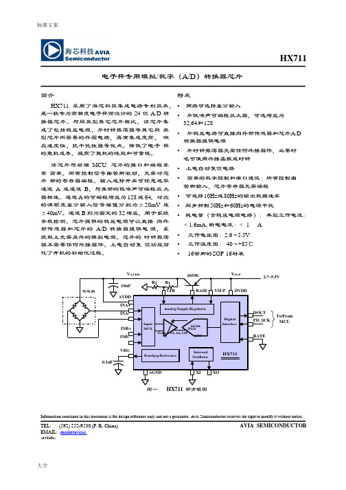
标准文案大全DigitalInterfaceAnalog Supply RegulatorInputMUXInternalOscillatorBandgap ReferenceHX711电子秤专用模拟/数字(A/D)转换器芯片简介HX711 采用了海芯科技集成电路专利技术,是一款专为高精度电子秤而设计的 24 位 A/D 转换器芯片。
与同类型其它芯片相比,该芯片集成了包括稳压电源、片时钟振荡器等其它同类型芯片所需要的外围电路,具有集成度高、响应速度快、抗干扰性强等优点。
降低了电子秤的整机成本,提高了整机的性能和可靠性。
该芯片与后端MCU 芯片的接口和编程非常简单,所有控制信号由管脚驱动,无需对芯片部的寄存器编程。
输入选择开关可任意选取通道A 或通道B,与其部的低噪声可编程放大器相连。
通道 A 的可编程增益为 128 或 64,对应的满额度差分输入信号幅值分别为±20mV 或±40mV。
通道 B 则为固定的 32 增益,用于系统参数检测。
芯片提供的稳压电源可以直接向外部传感器和芯片的A/D 转换器提供电源,系统板上无需另外的模拟电源。
芯片的时钟振荡器不需要任何外接器件。
上电自动复位功能简化了开机的初始化过程。
特点•两路可选择差分输入•片低噪声可编程放大器,可选增益为32,64 和128•片稳压电路可直接向外部传感器和芯片A/D 转换器提供电源•片时钟振荡器无需任何外接器件,必要时也可使用外接晶振或时钟•上电自动复位电路•简单的数字控制和串口通讯:所有控制由管脚输入,芯片寄存器无需编程•可选择10Hz 或80Hz 的输出数据速率•同步抑制50Hz 和60Hz 的电源干扰•耗电量(含稳压电源电路):典型工作电流:< 1.6mA, 断电电流:< 1 A•工作电压围:2.6 ~ 5.5V•工作温度围:-40 ~ +85℃•16 管脚的S OP-16 封装V AVDD10uF R2 R1S8550V SUP 2.7~5.5V传感器AVDDINA+INA-INB+INB-VFBPGAGain = 32, 64, 128BASE VSUP DVDD24-bitADCDOUTPD_SCKRATETo/FromMCU0.1uF VBGHX711 AGND XI XO图一HX711 部方框图Information contained in this document is for design reference only and not a guarantee. Avia Semiconductor reserves the right to modify it without notice. TEL: (592) 252-9530 (P. R. China) AVIA SEMICONDUCTOR EMAIL: marketaviaic..aviaic.大全管脚说明稳压电路电源 VSUP DVDD 数字电源稳压电路控制输出BASE RATE 输出数据速率控制输入 模拟电源 AVDDXI 外部时钟或晶振输入 稳压电路控制输入VFB XO 晶振输入 模拟地 AGND DOUT 串口数据输出参考电源输出 VBG PD_SCK 断电和串口时钟输入通道A 负输入端 INNA INPB 通道B 正输入端 通道A 正输入端INPAINNB通道B 负输入端SOP-16L 封装表一 管脚描述主要电气参数AA(1)有效位数E NBs(Effective Number of Bits) = ln(FSR/RMS Noise)/ln(2)。


蝶阀>>脱硫蝶阀>>脱硫蝶阀产品名称:脱硫蝶阀产品型号:D71X产品口径:DN40~DN1000产品压力:1.0~2.5MPa产品材质:铸铁、铸钢、不锈钢等产品概括:生产标准:国家标准GB、机械标准JB、化工标准HG、美标API、ANSI、德标DIN、日本JIS、JPI、英标BS生产。
阀体材质:铜、铸铁、铸钢、碳钢、WCB、WC6、WC9、20#、25#、锻钢、A105、F11、F22、不锈钢、304、304L、316、316L、铬钼钢、低温钢、钛合金钢等。
工作压力1.0Mpa-50.0Mpa。
工作温度:-196℃-650℃。
连接方式:内螺纹、外螺纹、法兰、焊接、对焊、承插焊、卡套、卡箍。
驱动方式:手动、气动、液动、电动。
产品详细信息D71X脱硫蝶阀产品介绍:大气污染中,二氧化硫是重要污染物,而二氧化硫污染物60%以上来源于工业烟气的排放。
随着我国环境标准的逐步完善和提高,以及国民对环境意识的提高,我国今后对有工业烟气排放的工程必须进行脱硫处理。
烟气脱硫装置中的重要部件之一就是阀门,对于脱硫阀门的要求是既能耐氯化物、氧化物、酸,又能耐苛刻的磨粒磨损和泥浆的磨损腐蚀。
正确的选择阀门材料和结构形式,延长阀门的使用寿命是烟气脱硫蝶阀的关键。
在众多的工业或电力领域需要有一套完整的脱硫系统.目前,国际上采用的是石灰石-石膏湿法,一炉一塔脱硫装置,该脱硫装置的脱硫效率可达到95.5%。
石灰石浆液系统经过脱硫管道后介质会出现较强的腐蚀性,对整个管道系统和流体控制阀门以及阀门执行器都有着极高的要求。
脱硫专用蝶阀就是针对脱硫系统的特殊要求设计制造的。
脱硫脱硝蝶阀专为电厂脱硫脱硝工程而设计,充分考虑了脱硫浆液对阀门的腐蚀和磨损,保证阀板衬里是唯一能够接触到浆液的部件,而其他部件不被石灰石(或石灰膏)浆液腐蚀。
因此,阀体和阀杆就不需要采用昂贵的合金(2205)材料,从而大大节约了成本。
脱硫蝶阀独特的阀座设计完全把阀体与流体介质隔开,与其他同类阀门比较,它有更佳的阀座牢固方式、就地更换阀座快捷、阀门保持零泄漏、且摩擦小。
Advance Data Sheet April 2000D571-Type Digital 1.5 µ m Uncooled DFBFastLight ™ Laser ModuleThe low-profile D571-Type Laser Module is ideally suited for L u c e n t D 571-10A S /N -L 651036 s Hermetically sealed active components s Internal back-facet monitorsQualification program: Telcordia Technologies * TA-983* Telcordia Technologies is a trademark of Bell Communications Research, Inc.ApplicationssLong-reach SONET OC-3/STM-1, OC-12/STM-4 systemss Telecommunications sSecure digital data systemsBenefitss Easily board mounted s Requires no lead bending s No additional heat sinks requiredsPin compatible with industry-standard 14-pin laser modulesHighly efficient DFB-MQW laser structure allows for lower threshold and drive currents, and reduced power consumptionDescriptionThe D571-Type Uncooled Laser Module consists of a laser diode coupled to a single-mode fiber pigtail. The device is available in a standard, 8-pin configu-ration (see Figure 1 and/or Table 1) and is ideal for long-reach (SONET) and other high-speed digital applications.The laser diode is a narrow linewidth (<1 nm) DFB-MQW single-mode laser and an InGaAs PIN photo-diode back-facet monitor in an epoxy-free, hermeti-cally sealed package.元器件交易网D571-Type Digital 1.5 µ m Uncooled DFB Advance Data SheetFastLight Laser ModuleApril 20002Lucent Technologies Inc.Description (continued)The device characteristics listed in this document are met at 2.0 mW output power. Higher- or lower-power operation is possible. Under conditions of a fixed pho-todiode current, the change in optical output is typically ± 0.5 dB over an operating temperature range of –40 ° C to +85 ° C.This device incorporates the new Laser 2000 manufac-turing process developed by the Optoelectronic unit of Lucent Technologies Microelectronics Group. Laser 2000 is a low-cost platform that targets high-volume manufacturing and tighter product distributions on all optical subassemblies. The platform incorporates an advanced optical design that is produced on a highly automated production line. The Laser 2000 platform isqualified for the central office and uncontrolled environ-ments, and can be used for applications requiring high performance and low cost. Table 1. Pin DescriptionsPin NumberConnection 1NC/Reserved 2Case ground 3NC/Reserved 4Photodiode cathode 5Photodiode anode 6Laser diode cathode 7Laser diode anode 8NC/ReservedFigure 1. D571-Type Digital Uncooled DFB Flat-PAC Laser Module Schematic, Top ViewAbsolute Maximum RatingsStresses in excess of the absolute maximum ratings can cause permanent damage to the device. These are abso-lute stress ratings only. Functional operation of the device is not implied at these or any other conditions in excess of those given in the operations sections of the data sheet. Exposure to absolute maximum ratings for extended periods can adversely affect device reliability.* Rating varies with temperature.ParameterSymbol Min Max Unit Maximum Peak Laser Drive Current or Maximum Fiber Power* I OP P MAX ——15010mA mW Peak Reverse Laser Voltage:Laser MonitorV RL V RM ——220V V Monitor Forward CurrentI FD —2mA Operating Case Temperature Range T C–4085 ° C Storage Case Temperature Range T stg –4085 ° C Lead Soldering Temperature/Time — —260/10 °C/s Relative Humidity (noncondensing)RH—85%1-900 (C)元器件交易网元器件交易网Advance Data Sheet D571-Type Digital 1.5 µm Uncooled DFBApril 2000FastLight Laser ModuleD571-Type Digital 1.5 µm Uncooled DFB Advance Data Sheet FastLight Laser Module April 20000.17(4.32)元器件交易网Advance Data Sheet D571-Type Digital 1.5 µm Uncooled DFBApril 2000FastLight Laser ModuleD571-Type Digital 1.5 µm Uncooled DFB Advance Data Sheet FastLight Laser Module April 200010 mW 1.5 µmAdvance Data Sheet D571-Type Digital 1.5 µm Uncooled DFB April 2000FastLight Laser ModuleFor additional information, contact your Microelectronics Group Account Manager or the following:INTERNET:/micro, or for Optoelectronics information, /micro/optoE-MAIL:docmaster@N. AMERICA:Microelectronics Group, Lucent Technologies Inc., 555 Union Boulevard, Room 30L-15P-BA, Allentown, P A 181031-800-372-2447, FAX 610-712-4106 (In CANADA: 1-800-553-2448, FAX 610-712-4106)ASIA PACIFIC:Microelectronics Group, Lucent Technologies Singapore Pte. Ltd., 77 Science Park Drive, #03-18 Cintech III, Singapore 118256 Tel. (65) 778 8833, FAX (65) 777 7495CHINA:Microelectronics Group, Lucent Technologies (China) Co., Ltd., A-F2, 23/F, Zao Fong Universe Building, 1800 Zhong Shan Xi Road, Shanghai 200233 P. R. China Tel. (86) 21 6440 0468, ext. 316, FAX (86) 21 6440 0652JAP AN:Microelectronics Group, Lucent Technologies Japan Ltd., 7-18, Higashi-Gotanda 2-chome, Shinagawa-ku, Tokyo 141, Japan Tel. (81) 3 5421 1600, FAX (81) 3 5421 1700EUROPE:Data Requests: MICROELECTRONICS GROUP DATALINE: Tel. (44) 7000 582 368, FAX (44) 1189 328 148Technical Inquiries:OPTOELECTRONICS MARKETING: (44) 1344 865 900 (Ascot UK)Lucent Technologies Inc. reserves the right to make changes to the product(s) or information contained herein without notice. No liability is assumed as a result of their use or application. No rights under any patent accompany the sale of any such product(s) or information. FastLight is a trademark of Lucent Technologies Inc.Copyright © 2000 Lucent Technologies Inc.All Rights ReservedApril 2000DS00-136OPTO (Replaces DS99-056LWP)。