MD751无绳使用说明书
- 格式:docx
- 大小:11.46 KB
- 文档页数:1


EW-7438RPn Mini 是專為延伸跨樓層、多房間的無線Wi-Fi 訊號所設計的多功能迷你無線訊號延伸器,它能延伸家中現有的無線網路、有效減少訊號死角,大幅提昇上網品質。
同樣具備三合一功能設計,不同於前一代EW-7834RPn V2設計, EW-7834RPn Mini 除了擁有更好的傳輸效能,它巧妙運用簡約美學的工業設計,將體積縮減16%,不僅不會干擾鄰座電源插孔的使用,且減少塑料使用,讓環境少ㄧ些負擔,同時EW-7438RPn Mini 更提供免費EdiRange App (適用於無線訊號延伸模式Wi-Fi Extender Mode 下),無論 iOS 或Android 都適用,讓您能輕鬆操作和管理如無線排程及訪客網路等功能,化繁為簡的設計,省空間省體積但絕不會省效能。
EW-7438RPn Mini 萬用相容的設計,可適用各家廠牌的無線分享器,而挑戰全台最簡易的安裝設定方式和最方便的使用方式,EW-7438RPn Mini 更是當之無愧,不僅同時具備可快速與上層無線分享器連線的WPS 按鍵,也提供獨家iQ Setup 超簡易設定方式,讓找不到分享器WPS 按鍵的朋友(如使用中華電信所提供的家用無線路由器)也能安心輕鬆完成安裝連線。
延續前一代EW-7834RPn Mini 設計,EW-7438RPn Mini 不僅可做Wi-Fi 訊號延伸,還可當做AP(將有線訊號轉為無線訊號)或AP Client(將無線訊號轉為有線訊號)來使用,多功能設計優化您家中的無線環境,讓您隨時都能享受穩定、高品質的無線網路。
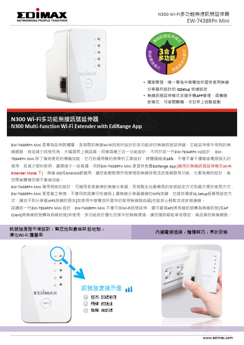
訊號強度指示燈設計,幫您找到最佳架 設地點, 優化Wi-Fi 覆蓋率© EDIMAX Technology Co., Ltd. All Rights Reserved.•獨家開發,唯一專為中華電信所提供家用無線分享器所設計的 iQSetup 快速設定•無線訊號延伸模式支援手機APP 管理,具備晚安模式,可夜間關機,次日早上自動啟動內建電源插頭,體積輕巧,易於安裝訊號強度指示燈N300 Wi-Fi 多功能無線訊號延伸器N300 Multi-function Wi-Fi Extender with EdiRange AppEW-7834RPn Mini2) iQ Setup 超簡易設定 :找不到分享器的WPS 按鍵,沒關係!只要使用iQ Setup ,不管家裏是哪個牌子的無線分享器,通通都能連,而且透過智慧型手機就可以設定,不開電腦也行。

纵观收音机电路,其组成莫过于放大器和各种滤波器者。
由于它要处理各种频率之信号,需要的频率比如中频信号和正在接收的某个频率信号,要让它们以最小的阻碍通过并根据需求进行放大,对于不需要的频率譬如不是想要接收的空中传输的各个发射台信号,收音机自身由于混频,交调,器件之非线性等所产生的各种新频率信号要为之设置最大的阻碍不许它们进入放大器。
一部优秀的收音机他的接收部分中的滤波器件对这些个各种频率的电信号的那绝对是爱憎分明的;如果收音机中相应的滤波器对待敌我频率的阶级立场不够坚定,那它决不会是一只好鸡。
那么怎样才能知道我们的收音机对他要的信号足够友好,而又对他不该要的信号有足够的抵制能力涅?科学家们搞了个叫做啥“扫频仪”的玩意儿专门来查看,当然不光是查看而已,还可以一边调整机机里面的滤波器件(主要是那些俗称中周的家伙),一边用这个东西来实时监视调整过程中的达到的效果,直到使我们满意为止.扫频仪何能何德有如此之能力?原来他自身能够产生一定频率范围内的所有信号,包括收音机需要的和应该要强加抵制的。
这些个频率的信号由低到高(当然如果你喜欢也可以由高到低的干)的挨个儿的扫过去,故得扫频仪之名也。
这些从扫频仪出来的扫频信号,虽然频率不一样,但个头大小可是完全相等的,它们进入一个正常的收音机后,该滤的滤掉,该放大的放大,最后可真是几家欢喜几家愁了,机机认为需要的信号被放大了N多倍,不需要的信号自然就被衰减到一个很小的值了。
扫频仪再由专门的探头去挨个儿察看经过机机的各个频率信号之大小,把这些大小值以频率为横轴,幅值之大小为纵轴,在显示屏上画出一个连续的曲线,我们只要一看到这个曲线马上就知道在扫频范围内不同频率的通过状况,再看看是不是我们想要的那个样子。
国产扫频仪的开山鼻祖当属变态三(BT-3),电子管的,那个头绝对的威猛,据说里面用了好多颗6N11的电子管,好东西来的,新的6N11可能40元RMB一颗也未必买到,我三天的饭钱也没这么多涅!这位老大后来可是儿孙满堂,晶体管版的,集成版的……统一的再在后面加字母以示辈分之高低,如BT-3B,BT—3C,BT-3H等等等等。

用户手册23.0MDaemon 电子邮件服务器用户手册v23.0.2 - 六月 2023Copyright © 1996-2023 MDaemon Technologies. Alt-N®, MDaemon®, and RelayFax®are trademarks of MDaemon Technologies.Apple is a trademark of Apple Inc. Microsoft and Outlook are trademarks of Microsoft Corporation. All other trademarks are the property of their respective owners.目录章节 I MDaemon Messaging Server 23.0 13 1MDaemon 功能 (14)2系统要求 (16)3MDaemon 新功能 23.0 (16)4升级到 MDaemon 23.0.2 (50)5获得帮助 (54)章节 II MDaemon 的主界面 57 1统计 (58)自动发现服务 (62)2事件跟踪与日志记录 (65)事件跟踪窗口的快捷菜单 (67)3综合日志视图 (67)4托盘图标 (68)快捷菜单 (69)锁定/解锁M D a e m o n的主界面 (69)5会话窗口 (69)6MDaemon 的 SM TP工作流 (70)章节 III设置菜单 73 1服务器设置 (74)服务器和投递 (74)服务器 (74)投递 (76)会话 (79)超时 (82)未知邮件 (83)D N S和I P (85)DNS (85)端口 (87)I P v6 (89)绑定 (90)I P缓存 (91)域共享 (93)公共文件夹和共享文件夹 (95)公共文件夹和共享文件夹 (97)邮件撤回 (99)主机验证 (101)优先级邮件 (102)报头转译 (103)报头转译例外 (104)归档 (105)清理 (107)签名 (109)默认签名 (109)默认客户端签名 (113)M u l t i P O P (118)D o m a i n P O P (122)主机&设置 (124)解析 (126)处理 (127)路由 (128)外来邮件 (130)名称匹配 (131)归档 (132)远程访问系统 (133)远程访问系统 (133)登录 (134)处理 (135)日志 (136)日志模式 (136)综合日志 (138)统计日志 (139)W indows 事件日志 (141)维护 (142)设置 (143)更多设置 (146)2域管理器 (149)主机名称&I P (151)智能主机 (153)账户 (155)M D I M (156)日历 (158)W e b m a i l (160)出队 (164)按需邮件中继(ODMR) (165)签名 (166)客户端签名 (170)设置 (175)A c t i v e S y n c (177)客户端设置 (178)策略管理器 (183)已分配策略 (190)账户 (191)客户端 (199)3网关管理器 (206)全局网关设置 (209)自动创建网关 (210)网关编辑器 (212)域 (212)验证 (213)配置多个L DA P验证队列 (215)转发 (217)出队 (218)配额 (220)设置 (222)4邮件列表管理器 (223)邮件列表设置 (225)邮件列表编辑器 (228)成员 (228)设置 (231)增强的列表清理 (232)报头 (233)订阅 (236)订阅邮件列表 (238)提醒 (239)摘要 (240)通知 (241)调节 (243)路由 (244)支持文件 (246)公共文件夹 (248)活动目录 (249)OD B C (251)配置 OD B C 数据源 (252)创建新的 OD B C 数据源 (254)5公共文件夹管理器 (258)访问控制列表 (260)6W e b& IM 服务 (266)W e b m a i l (266)概述 (266)日历和调度系统 (266)MDaemon Instant Messenger (267)即时通讯 (267)Drop b ox 集成 (268)使用W e b mail (269)W e b 服务器 (270)在 IIS6 下运行W e b mail (272)SS L&H TT P S (274)MDIM (278)日历 (279)空闲/忙碌选项 (280)RelayFax (281)Drop b ox (282)G oogle Drive (284)类别 (288)设置 (289)贴牌 (293)R e m o t e A d m i n i s t r a t i o n (293)W e b 服务器 (294)SS L&H TT P S (297)在 IIS 下运行 Remote Administration (300)使用条款 (304)附件链接 (305)C a l D A V&C a r d D A V (308)X M P P (312)7事件调度 (315)A n t i V i r u s调度 (315)反病毒更新 (315)调度 (316)邮件调度 (318)邮件发送&收集 (318)Multi P O P收集 (320)邮件调度 (322)8MDaemon C onne c t or (323)M C服务器设置 (324)设置 (324)账户 (325)M C客户端设置 (326)常规 (328)高级 (331)文件夹 (333)发送/接收 (334)其他选项 (335)数据库 (337)签名 (339)插件 (340)9集群服务 (341)选项/定制 (344)共享网络路径 (345)故障诊断 (347)10Ac t iveS y n c (349)系统 (349)微调 (351)客户端设置 (353)安全 (359)故障诊断 (361)协议限制 (363)域 (365)策略管理器 (372)账户 (380)客户端 (388)群组 (396)客户端类型 (402)11邮件索引 (408)选项/定制 (408)故障诊断 (409)12首选项 (411)首选项 (411)用户界面 (411)系统 (414)磁盘 (415)修复 (417)报头 (418)更新 (420)其他选项 (421)W i n d o w s服务 (423)章节 I V安全菜单 425 1安全管理器 (428)安全设置 (428)中继控制 (428)反向查询 (430)P O P先于 SMT P (433)可信主机 (434)可信 I P (435)发件人验证 (436)I P防护 (436)SMT P验证 (438)S P F 验证 (440)域名密钥标识邮件 (442)D K IM 验证 (443)D K IM 签名 (445)D K IM 设置 (447)DMARC (449)DMARC 验证 (454)DMARC 报告 (456)DMARC 设置 (459)邮件证书 (460)V B R 证书 (462)批准列表 (465)屏蔽 (466)发件人阻止列表 (466)收件人阻止列表 (467)I P屏蔽 (468)主机屏蔽 (470)SMT P屏蔽 (472)劫持检测 (473)Spam b ot 检测 (475)位置屏蔽 (477)发件人报头屏蔽 (478)S S L和T L S (479)MDaemon (481)W e b mail (483)Remote Administration (487)无 STARTT L S 列表 (491)STARTT L S 列表 (492)SMT P扩展 (493)DNSS E C (495)L et's E ncrypt (496)其他 (498)反向散射保护 - 概述 (498)反向散射保护 (499)带宽节流 - 概述 (500)带宽限制 (501)缓送 (503)灰名单 (505)局域网域 (507)局域网 I P (508)站点策略 (509)2动态屏蔽 (510)选项/定制 (510)验证失败跟踪 (513)协议 (516)通知 (517)故障诊断 (520)动态允许列表 (522)动态阻止列表 (524)域N A T豁免 (526)3MD P G P (527)4爆发保护 (535)5内容过滤器与反病毒 (539)内容过滤编辑器 (540)规则 (540)创建新的内容过滤器规则 (542)修改现有的内容过滤器规则 (546)在您的过滤器规则中使用正则表达式 (546)附件 (550)通知 (552)邮件宏 (553)收件人 (555)压缩 (556)A n t i V i r u s (558)病毒扫描 (558)反病毒更新程序 (562)更新程序配置对话框 (564)6垃圾邮件过滤器 (564)垃圾邮件过滤器 (564)垃圾邮件过滤器 (565)贝叶斯分类 (568)贝叶斯自动学习 (571)垃圾邮件守护进程(MDSpamD) (573)允许列表(自动) (575)允许列表(无过滤) (578)允许列表(按收件人) (579)允许列表(按发件人) (580)允许列表(按发件人) (581)更新 (582)报告 (583)设置 (584)D N S阻止列表(D N S-B L) (586)主机 (587)允许列表 (588)设置 (589)自动生成一个垃圾邮件文件夹和过滤器 (591)垃圾邮件蜜罐 (592)章节 V账户菜单 595 1账户管理器 (596)账户编辑器 (598)账户详细信息 (598)邮件文件夹&群组 (601)邮件服务 (602)W e b 服务 (603)自动应答器 (607)转发 (610)限制 (611)配额 (613)附件 (616)IMA P过滤器 (617)Multi P O P (620)别名 (622)共享文件夹 (623)访问控制列表 (624)应用程序密码 (630)签名 (632)管理角色 (636)允许列表 (637)设置 (639)ActiveSync for MDaemon (642)客户端设置 (643)已分配策略 (648)客户端 (649)2群组&模板 (657)群组管理器 (657)群组属性 (658)客户端签名 (661)模板管理器 (666)模板属性 (667)邮件服务 (670)W e b 服务 (672)群组 (675)自动应答器 (676)转发 (679)配额 (681)附件 (683)管理角色 (685)允许列表 (686)设置 (687)3账户设置 (689)活动目录 (689)验证 (692)监控 (694)L DA P (696)别名 (699)别名 (699)设置 (701)自动应答器 (703)账户 (703)附件 (704)豁免列表 (705)设置 (706)创建自动应答脚本 (707)自动应答脚本示例 (709)其他 (711)账户数据库 (711)OD B C 选择器向导 (712)创建一个新的数据源 (713)密码 (717)配额 (721)Minger (724)4导入账户 (725)从文本文件中导入账户 (725)W i n d o w s账户集成 (727)章节 V I队列菜单 731 1邮件队列 (732)重试队列 (732)保持队列 (734)定制队列 (736)还原队列 (737)D S N设置 (738)2预/后处理 (740)3队列和统计管理器 (741)队列页面 (742)用户页面 (744)日志页面 (746)报告页面 (748)定制队列与统计管理器 (749)MDstats.ini 文件 (749)MDStats 命令行参数 (750)章节 V II MDaemon 附加功能 751 1MDaemon 与文本文件 (752)2通过电子邮件远程控制服务器 (752)邮件列表和编录控制 (752)常规邮件控制 (754)3RAW 邮件规范 (755)R A W邮件规范 (755)绕过内容过滤器 (755)R A W报头 (755)R A W支持的专用字段 (755)R A W邮件示例 (756)4信号文件 (757)5路由名单 (762)章节 V III创建和使用 SS L证书 763 1创建一个证书 (764)2使用由第三方发行的证书 (764)章节 I X术语表 767索引785章节11MDaemon Messaging Server 23.0介绍MDaem on Technol ogi es 的MDaem on Messaging Server 是一个基于SMTP/POP3/IMAP 标准的邮件服务器,支持 Windows 7、Server 2008 R2或更高版本,并提供一套完整的邮件服务器功能。

◆上海业余无线电自带手台验机全功略◆上上周考出了业余无线电四级,原先自己有个灵通的6100plus,昨日到人民路879号17F 验机,早就耳闻一次通过率很低,所以事先做了些准备,毕竟请两天假代价不小的,呵呵~(图中竖箭头处一排为停车点,路口有提示排说停车收费,我停了两小时,也没人来收费,倒是招来了JC,直接200门,不管它了,反正杭州牌,扔了走人~)弧形箭头为入口,电梯直达17F,灰常老灰常慢的电梯……事先在BAIDU上搜了一下,看到貌似有些XD说自带机验机需要锁频到433~436范围内,怎么个锁法当然我们这没有软件可以进工程模式,于是网上有XD提出用贴条大法,即用3M 胶条贴掉所有数字和功能按键背面的触发点,以使手台只可在已存储的433~436频点切换。
但昨日实际尝试中发觉此方法有弊端,即贴薄了按钮仍然有效,贴厚了会使喇叭断路无声,几经折腾,在一旁无委老师的“提醒”下,索性拆了整个键盘以达到使键盘失效的目的,哈哈~验机通过,当然品相是差了点,不过这个大家都懂的,拿到合格标签后再把键盘装回去就是了~以下是拆机的全过程,其它机型可仿效,目的是一样的:拆下键盘!准备工作:1. 至少存储一个433~436之间的频点,比如433.550。
不会存储?我下面再转个6100中继亚音和存储设置备忘录给各位;2. 把已存储的频点发射功率调到LOW。
不会设置?呵呵~仔细看下面的文章,会提到;3. 十字螺丝刀一把(起十字螺丝用),一字螺丝(撬开外壳用)Let's GO!!!第一步:卸下6100手台背面的卡夹第二步:卸下电池后起掉背面下方的两颗螺丝及侧面的耳机盖板第三步:拔掉POWER旋钮,转下天线第四步:起掉POWER旋钮和天线下面的两块固定垫片然后按先蓝色箭头方向后红色箭头方向小心退出外壳(此步着力点在红色箭头处,因为此侧面有两个耳机插孔挡住,所以有个外掰的力。
蓝色箭头只是辅助,先起个0.5CM就可以了)第五步:如图所示,不必完全退出,这个角度已经可以取出整块硅胶键盘了第六步:合上外壳,装上电池,开机验机,一次通过!!!LT-6100PLUS拆剖全景图,注意红色圆圈处为喇叭接口,实测用垫片大法实现键盘失效后喇叭接口会因被垫高而断路失声;附录:灵通6100plus使用中继详细设置步骤(目前市场流行的国产手台)1. 设置接收频率:按下“V/M” 键,选择频率显示模式,输入接收频率***.***。

松下无绳电话通用说明指导手册面板按键说明MENU(菜单) (停止播放留言)ERASE(删除留言)GREETING REC(录制对外留言)GREETING CHECK(核对已录制的对外留言) (调高音量) (调低音量) (重复) (前进) (播放留言)LOCATOR/ INTERCOM(呼叫/内部对讲)ANSWER ON(答录机开关)CONF (三方会谈)MEMO(录制家庭留言)SP-PHONE(免提键)TALK(播打或接听电话)OFF(挂机)快速进入菜单功能的操作说明:按MENU -- #1、输入下表相对应的代码2、操作完成后,按右软键SA VE保存当前设置基本设置(以下操作需在待机状态下进行)显示语言设置:MENU→ # 1 1 0,使用上下翻页键选择语言。
拨号方式设置:MENU→ # 1 2 0,使用上下翻页键选择TONE(音频)PUSLE(脉冲)。
时间与日期设置:MENU→ # 1 0 1,按顺序输入月、日期与年份,每一个对应两位数字;相同的输入当前的小时与分钟,也是对应两位数字;用左软键选择AM(上午)或PM(下午),Save→OFF (注意,如果选择显示语言是英文,则时间显示支持12小时制,如果是西班牙文则支持24小时制)答录系统设置录制对外留言:按一下主机的GREETING REC 键,听到声音后,再按一次听到“嘟”声就开始录制,录完结束,按 键;按GREETING CHECK 可以试听已录制的对外留言。
删除对外留言:在试听时,按ERASE键就会删除先前录制的对外留言。
子机注册新的子机需要注册才能正常使用,按照上面的图表指示操作,menu---> Initail setting --->Registration--->HS registration--->再按右软件键(Select),屏幕显示为“Press LOCA TOR on base for 4sec Then press OK”,此时按住主机的呼叫键LOCATOR/ INTERCOM 直到主机发出有规律的声音后才放开,再按手机的右软键即OK,等待自动注册!注册过程中,屏幕显示为“error!”,请按挂机键OFF,再按一下手机的右软键即OK;或者重新上述步骤!解除注册按照上面的图表指示操作,menu---> Initail setting --->Registration--->Deregistration--->输入代码335,选择要解除的子机号(1-6),听到一长的“嘟”声,表示成功解除!如果屏幕显示为“error!”,则有可能该子机号没有注册过!9331子机取消英文报号:待机状态下,按中间的menu键,再按向下翻页键6次,屏幕显示为Talking CallerID,后按select(即右软键),后使用上或下翻页键选择Off,再按Save(即右软键)9331主机取消英文报号:待机状态下,按中间的menu键,再按向上翻页键2次,屏幕显示为Initial setting,后按select(即右软键),后使用上或下翻页键找到Set base unit选项,后按select(即右软键),此时屏幕显示为Talking CallerID,接下来操作跟子机的取消操作一样!9331 远程操作答录机1、在外拨打家里的号码2、当听到答录机的对外留言时,输入远程进入的密码,默认是111(后面会提到如何设置新的远程密码)2.1 进入后答录机会播放新的留言2.2 如果没有新的留言,答录机会语音提示如何操作答录机(请参考下面的数字键说明)3、按数字键进行答录系统操作4、完成后,挂机。

WelcomeQuick start guide123Connect Install EnjoyWhat’s in the boxHandset Base station Power supply for base station2 AAA rechargeable batteries Battery door Line cordQuick Start Guide Warranty cardUser Guide The line adaptor may not be attached to the line cord. In this case, you have to connect the line adaptor to the line cord first before plugging the line cord to the line socket.In multihandset packs, you will find one or more additional handsets, chargers with power supply units and additional rechargeable batteries.WARNING Always use the cables and batteries that came with your phone.1.Place the base station in a central location near the telephone line socket and electricity sockets.2.Connect the line cord and the power cable to the proper connector at the back of the base station.3.Connect the other end of the line cord to the telephone line socket and the other end of the power cable to the electricity socket.Connect the power supply 1.2.Connect the line cord to the line socket BA1ConnectConnect the base station Set date and time1.Press m .2.Scroll : to Clock & Alarm and press OK .3.Press OK to select Set Date/Time .4.Enter current time (HH:MM) and current date (DD/MM/YY) and press OK .Now, you are ready to use your phone.Insert batteriesCharge handset for 24 hours 2Install Insert batteries and charge3EnjoyMake a callEnter the phone number and press r .ORPress r and enter the phone number.Answer a callWhen the phone rings, press r key.End a call Press e key.Adjust earpiece volume during a callPress : to select from V olume 1 to V olume 5.Store a contact in the phonebook1.Press m , scroll : to Phonebook and press OK , press OK again to select New Entry .2.Enter the name of the contact (maximum 12 characters) and press OK .3.Enter the number (maximum 24 digits) and press OK .4.Enter the SMS box number and press OK (only for UK).(The default SMS Box is 9. To modify, press BACK and then enter the number (0 to 9).)5.Scroll : to a group (<No Group>, <Group A>, <Group B>, <Group C>) and press OK to confirm.A long confirmation beep tone is emitted.Access the phonebook1.Press d in standby mode or press m , scroll : to Phonebook and press OK , scroll : to List Entry and press OK .2.Press : to browse the phonebook.Set the ring melody1.Press m , scroll : to Personal Set and press OK , press OK to select Handset Tones , scroll :to Ring Melody and press OK .2.Scroll : to your desired melody to play the melody.3.Press OK to set your ring melody.A confirmation beep is emitted and the screen returns to previous menu.m Enter the main menu from stand-by mode.Select the function displayed on the handset screen directly above it.>Go to redial list from stand-by mode.Select the function displayed on the handset screen directly above it.Activate mute function during a call.r Answer an incoming external or internal call.Insert R for operator services when on the line.e Hang up a call.Long press from menu browing to return to stand-by mode, short press to return to previous menu.Long press in stand-by mode to switch off the handset, short press to switch on the handset again.u Access call log from stand-by mode.Scroll up a menu list or go to the previous phonebook or call log record.Increase earpiece volume during a call.Go to the previous character in editing mode.d Access phonebook from stand-by mode.Scroll down a menu list or go to the next phonebook or call log record.Decrease earpiece volume during a call.Go to the next character in editing mode.c Initiate an internal call.v Answer an incoming call in handsfree mode.Activate and deactivate the loudspeaker during a call.#Dial # in stand-by mode.Long press to mute the ringer in stand-by mode.Insert a pause in dialling mode.Switch between upper and lower case in editing mode.*Dial * in stand-by mode.Long press to activate and deactivate keypad lock.Switch the handset On/OffPress and hold e key for 5 seconds to switch off the handset in stand-by mode.Short press e key to switch on the handset again.Keypad lock/unlockPress and hold * key for 2 seconds to lock and unlock keypad in stand-by mode.Paging 1.Press c key on the base until the handset starts to ring.2.Once the handset is retrieved, press e to end the paging.3111 265 27381TroubleshootingFor more information, please refer to p.48 of SE430 user manual and p.56 of SE435 user manual. Need help?User ManualRefer to the User Manual that is supplied with your SE430/435.Online helpProblemSolution • No dialling tone • Check the connections• Charge the batteries for at least 24 hours• Use the line cable provided• Poor audio quality • Move closer to the base station• Move the base station at least one metre away from any electrical appliances• The icon is blinking • Register the handset to the base station• Move closer to the base station• Caller Line Identification (CLI) service does not work • Check your subscription with your network operator。


IC-7113W愛家無線網路攝影機包裝內容IC-7113W安裝指南 壁架底座電源變壓器網路線螺絲LED指示燈硬體安裝請按照下面的說明以確保您的攝影機已正確連接並安裝就緒。
1.請將電源變壓器連接至產品本體後方的電源連接埠,並將插頭端插入電源插座。
2.請稍待本產品開機完成。
當產品本體的LED燈號呈現紅燈閃爍的狀態,代表安裝模式已就緒,此時機器內建的喇叭會播放提示聲響。
3.請使用您的手機或平板,依您其作業系統至Google Play或Apple AppStore搜尋〝EdiLife〞APP,然後下載並安裝。
4.請在啟動EdiLife之前,先前往您手機或平板電腦的Wi-Fi設定,並連接到您網路攝影機預設的無線名稱SSID (EdiView.Setup **),最後兩碼**即為您的網路攝影機所獨有的MAC 位址的最後兩碼。
5.接著點選執行EdiLife (如下左圖示) 後,點擊視窗畫面右上方的+圖示(如下右圖示)。
6.自可用的無線裝置清單中選擇您的無線網路攝影機後,耐心稍待APP建立連線。
若您未看到您想要連線的無線網路攝影機,請點擊右上角的”重新整理” 圖示。
7.為了安全考量,請您務必輸入新的裝置名稱和密碼[8碼以上英文及數字組合] 方可進行下一步驟。
接著,請點選(確認) 以繼續。
8.請從選擇“Wi-Fi清單”中選擇您的網路攝影機所要連接的無線網路(分享器/基地台),然後輸入您的無線網路密碼後,再點擊下一步。
若您未看到您想要連線的Wi-Fi無線網路,請點擊右上角的”重新整理”圖示。
9.請稍候您的IC-7113W連接到您的無線網路。
當你看到"設定成功" 畫面後已正確完成設定,再按下"完成" 圖示以繼續,或等待數秒自動繼續。
10.安裝完成後,此時IC-7113W的綠色電源LED指示燈及橘色InternetLED燈應為恆亮狀態。
現在您的IC-7113W網路攝影機應該已經出現在EdiLife的主頁畫面中,只要連線Internet,您就隨時隨地點擊您清單中的IC-7113W,觀看其所拍攝的即時影像了。

G2PHOENIX PRIME : DL369Functions • 750V AC/1000V DC • 400A AC • 2000µA AC/DC • 40MΩ Resistance/Continuity • 4000µF Capacitance • Non-Contact Voltage 24~600V AC • Frequency/Duty Cycle • Diode • Data Hold • MIN/MAXFeatures • Dual Display • Low Battery Display Lock • Test Lead Storage • Test Lead Holder on Clamp Head • Auto Off • Three Year Limited WarrantySafety Compliance • CATIII 600V, CATII 1000VAccessories included • Test Leads • Zippered Case • 2AAA batteries Functions • Measures 100A AC • Non-Contact Voltage in tip • Worklight • Patented Virtual Closed Core Accuracy • Works exclusively with the PRO and PRO+*• Three year limited warrantySpecifications • Range: 0 – 100A • Resolution: 0.1A • Accuracy: 2.0% ±20 dgts • Interference from adjacent wires: 0.03 – 1.0A*Hook does not measure True-rms when used with the PRO+ (DL389)G2PHOENIX PRO : DL379Functions • All the DL369 Functions PLUS...• -40 ~ 752°F Temperature (K type)Features • All the DL369 Features PLUS...• Input Jack Lock • Detachable Clamp Head • Worklight • Magnetic Mount • User Temperature Calibration • EasyView High Contrast Backlight Display • Compatible with common Industry Accessories Heads • Three Year Limited Warranty Safety Compliance • CATIII 600V, CATII 1000V Accessories included • Test Leads • K type probe (no adapter required)• Zippered Case • 2AAA batteries G2PHOENIX PRO+: DL389Functions • All the DL369 Functions PLUS...• TRUE-RMS(AC Volts & AC Amps)• -40 ~ 752°F Temperature (K type)Features • All the DL369 Features PLUS...• Input Jack Lock • Detachable Clamp Head • Worklight • Magnetic Mount • User Temperature Calibration • EasyView High Contrast Backlight Display • Compatible with common Industry Accessories Heads • Three Year Limited Warranty Safety Compliance • CATIII 600V, CATII 1000V Accessories included • Test Leads • K type probe (no adapter required)• Zippered Case • 2AAA batteriesG2PHOENIX HOOKExtended Clamp Head: CH3INCREASED SAFETYINPUT JACK LOCK: Prevents temperature probe and test leads from being simultaneously connected to the meter. This is a great safety device protecting users against a potentially harmful yet common error.*LOW BATTERY INDICATOR: This warning prevents use when the battery is too low to provide accurate readings.NCV ALARM: The newly enhanced audible alarm gives contractors an accurate indication of live voltages. The easily distinguishable tones are synchronized with a red LED warning light.ENHANCED FUNCTIONALITYCAPACITANCE: Select the capacitance function easily by turningthe selector dial. The G2 Phoenix indicates this function with the microfarad symbol “ “ and abbreviation “MFD”.NCV SENSOR: The voltage sensor is relocated to the clamp head’s wire sorting tip and features improved sensitivity, providing added convenience and increased detec-tion reliability.TEMPERATURE CALIBRATION: Allows users to recalibrate temperature in the field eliminating down time and saving money.*MANUAL RANGING:The User can select manual ranging on either the upper or lower display screen. Select the proper range for the function to speed up testing, and to capture maximum values more accuratelyG2PHOENIX: Upgrades at a glance ...................................................................* Features are exclusive to the G2PHOENIX PRO (DL379) and PRO+ (DL389).COMFORTABLE INTERFACEEASYVIEW DISPLAY: We’ve added the EasyView high contrast backlit display to aid viewing in direct sunlight and dark work environments. The duration of the backlight has been increased allowing more time to connect to the test points and view results in the dark.*DUAL DISPLAY:The dual backlit display allows simultaneous measurements of current and voltage.USER INTERFACE: The popular thumb wheel navigation has been added providing users a firm ergonomic grip that allows for comfortable one-handed operation.UNPARALLELED INNOVATIONDETACHABLE CLAMP HEAD: Remove the clamp head to attach the HOOK Extended Clamp Head providing measurement capabilities into hard to reach areas. The G2 Phoenix also excepts common industry attachment heads .*THE HOOK: The HOOK offers a safe way to check amperage in tight spaces or wire bundles. Upgraded with a Non-Contact Voltage sensor in the tip and a Worklight, this patented technology increases accuracy by significantly reducing current interference from adjacent wires by providing a virtual closed core measurement in the HOOK.*WORKLIGHT: Dark work spaces are now illuminated adding both safety and convenience to the jobsite. Once activated the Worklight will stay illuminated for two minutes.*MAGNETIC MOUNT:The strong magnet built into the Phoenix housing offers users hands-free operation.*TEST LEAD STORAGE:Test leads snap into the back of the meter’s housing covering the sharp probes and keepingthe leads readily available....................................* Features are exclusive to the G2PHOENIX PRO (DL379) and PRO+ (DL389).AC Amps Measurement - Jaw Input (45Hz to 400Hz)*DL369 400A range only*DL389 45Hz to 400Hz True RMS (Crest factor <3:1)DC Low Amps Measurement (test lead input)AC Low Amps Measurement (test lead input)*DL389 45Hz to 400Hz True RMS (Crest factor <3:1)DC Volts MeasurementAC Volts Measurement (45Hz to 400Hz)*DL389 45Hz to 400Hz True RMS (Crest factor <3:1)Ohms Measurement Diode TestCapacitance MeasurementTemperature Measurement (DL379 & DL389 only) Frequency MeasurementMinimum frequency: 0.5Hz, DC V offset should be zeroSensitivity: > 1.0V rmsDuty (%) Cycle Measurement0.5Hz to 100KHz (pulswidth > 2µ sec)Continuity MeasurementRange Resolution Accuracy Overload Protection 40A 0.01A ±2.9% +15 dgts 600V400A 0.1A ±1.9% +8 dgtsRange Resolution Accuracy Overload Protection 400µA 0.01µA ±1.2% +3 dgts 2000µA / 600V 2000µA 0.1µARange Resolution Accuracy Overload Protection 400µA 0.01µA ±2.0% +5 dgts 2000µA / 600V 2000µA 0.1µA ±1.5% +5 dgtsRange Resolution Accuracy Overload Protection 400mV 0.1mV ±0.5% +4 dgts 600V4V 1mV40V 10mV400V 100mV1000V 1V ±0.8% +10 dgtsRange Resolution Accuracy Overload Protection 4V 1mV ±2.0% +5 dgts 600V40V 10mV400V 100mV750V 1VRange Resolution Accuracy Overload Protection 400Ω100mΩ±1.0% +4 dgts 600V4kΩ1Ω40kΩ10Ω400kΩ100Ω4MΩ 1kΩ40MΩ 10kΩ ±2.0% +4 dgts Range Open Circuit Voltage Test Current (typical) Overload Protection 2.0V < 3.0V DC 0.25mA 600VRange Resolution Accuracy Overload Protection 40nF 0.01nF ±3.5% +6 dgts 600V400nF 0.1nF4µF 0.001µF40µF 0.01µF400µF 0.1µF4000µF 1µFRange Resolution Accuracy Overload Protection -22˚ to 14˚F 0.1˚F ±5.4˚F 30V(-30˚ to -10˚C) (0.1˚C) (±3.0˚C)15˚ to 752˚F 0.1˚F ±1.0% +3.6˚F(-9˚ to 400˚C) (0.1˚C) (±1.0% +2.0˚C)Range ResolutionAccuracy Overload Protection 9.999Hz 0.001Hz ±0.1% +4 dgts 600V99.99Hz 0.01Hz999.9Hz 0.1Hz9.999kHz 1Hz99.99kHz 10HzRange Accuracy Overload Protection 01. to 99.9% ±(0.2% per kHz +0.1%) +5 count 600VOpen Circuit voltage <2.7V Overload Protection Threshold Approximately <20Ω600VG2PHOENIX: specifications................................G2PHOENIX: selection gUideIf You Measure... PRIME PRO PRO+ G2PHOENIX Features DL369 DL379 DL389 Non-linear loads or distorted waveforms: X TRUE RMS Fahrenheit or Celsius: X X Temperature Use HOOK clamp head & attachment heads: X X Detachable Clamp Head Illuminate dark work environments: X X Worklight Hands free: X X Magnetic Mount In either dark or bright sunlit work spaces: X X EasyView Backlit Display Motor run or start faults: X X X Capacitance Flame safe guard: X X X AC/DC Microamp Quick check of live wires: X X X Non-Contact Voltage Motor in-rush: X X X MIN/MAX and Data Hold Two readings simultaneously: X X X Dual Display Control voltage or System board voltage checks: X X X AC/DC Volts Motor or line current: X X X AC Current: Circuit continuity or specified resistance: X X X Resistance Variable speed drives & supply power: X X X Frequency With increased measurement speed & accuracy: X X X Auto/Manual Ranging Variable speed drives & supply power: X X X Duty Cycle Diode malfunctions/Unbroken paths: X X X Diode/Continuity Test Convenient storage: X X X Test Lead Storage Hands free of test leads: X X X Test Lead Holder Safety compliance: X X X CAT III 600V, CAT II 1000V Peace of mind: X X X3-Year Limited Warranty Copyright © 2008 UEi. PHOENIX Clamp Meter Series™ is a trademark of UEi. All Rights Reserved. Specifications are subject to change without notice. L305 PARA110.30k 0508DISTRIbUTED BY :C h o o s e a m e t e r th a t d o e s e v e r y t h i n g y o ud o !PLEASERECYCLE。

家用无绳洗地机操作方法
家用无绳洗地机的操作方法一般如下:
1. 准备洗地机:将洗地机放在平坦的地面上,确保无任何障碍物。
2. 加入清洁剂:根据洗地机说明书的指示,将清洁剂加入洗地机的水箱中,并按要求加入适量的水。
3. 启动洗地机:找到洗地机上的电源开关并打开,此时洗地机就会开始工作。
4. 操作手柄:拿起洗地机的操作手柄,将其推入水平位置。
一些洗地机还会有不同模式的选择,可以根据需要选择合适的模式。
5. 开始清洁:将洗地机的刷盘放在地面上,开始清洁。
根据需要的清洁面积和方式,可以选择前进、后退、左右移动等动作,确保每个角落都得到充分的清洁。
6. 结束清洁:当清洁完成后,将洗地机的操作手柄推回原来的位置,然后关闭电源开关。
7. 清洁洗地机:将洗地机的刷盘和水箱取出,并用清水和清洁剂彻底清洗干净。

USER MANUALWireless Belt Station, non-VOXU9912-BSW (P/N: 40992G-02)C a u t i o n s a n d W a r n i n g sREAD AND SAVE THESE INSTRUCTIONS. Follow the instructions in this installationmanual. These instructions must be followed to avoid damage to this product andassociated equipment. Product operation and reliability depends on proper usage.DO NOT INSTALL ANY DAVID CLARK COMPANY PRODUCT THAT APPEARS DAMAGED. Upon unpacking your David Clark product, inspect the contents for shipping damage. If damage is apparent, immediately file a claim with the carrier and notify your David Clark product supplier.ELECTRICAL HAZARD - Disconnect electrical power when making any internal adjustments or repairs. All repairs should be performed by a representative or authorized agent of the David Clark Company.STATIC HAZARD - Static electricity can damage components. Therefore, be sure to ground yourself before opening or installing components.LI-POLYMER - This product is used with Li-Polymer batteries. Do not incinerate, disassemble, short circuit, or expose the battery to high temperatures. Battery must be disposed of properly in accordance with local regulations.O v e r v i e wThe U9912-BSW (40992G-02) Wireless Belt Station is a portable wireless communication device that when used in conjunction with a U9911-BSC (41033G-01) Controller Belt Station or one ofthe U9900-series gateways becomes part of a wireless intercom system. Up to five users areable to communicate with each other when using the U9911-BSC. Up to four users are able tocommunicate with each other and also with a two-way radio or other wired intercom systemwhen using one of the U9900-series gateways. Only one gateway/controller is required persystem. Up to four belt stations can be connected to one controller/gateway.Figure 1: Overview of Belt StationThe U9912-BSW non-VOX Wireless Belt Station is commonly used where extremely high andvarying noise levels become challenging to a VOX belt station's settings, resulting in unwantednoise being present in a VOX belt station user's headset and causing him/her to frequently adjust the VOX setting. VOX belt stations may be desired in more stable and less extreme noiseenvironments.L i n k i n gBefore a belt station and a controller/gateway can be connected, they must first be Linked. As a security measure, the close-link feature requires devices to be in proximity of about 1 to 3 ft (0.3 to 0.9m) in order to successfully link. This ensures that the units are not inadvertently linked with other units on the premises.Linking procedure:1.Ensure units are within 1 to 3 ft (0.3 to 0.9m) of each other.2.Ensure the U9912-BSW is not already connected (see Status Indication).3.Simultaneously (within 1-2 sec) press and release the PTT button on the U9912-BSW andthe controller or gateway to link with.4.Amber LED’s will flash on both devices. A momentary red LED indicates a successfulclose-link.5.Upon successful link the U9912-BSW will attempt to establish a connection with thecontroller/gateway.6.Upon successfully establishing connection the LED will flash green, a voice alert will beheard (see Table 1), and user side-tone will be enabled (see Communication).7.Link and connection are now complete.Each belt station is able to be linked to only one gateway/controller at a time. A gateway/-controller can have up to six belt stations linked and be connected to four of those six at onetime.Tip:Once linked, the devices will not need to be linked again unless they are purged (seePurging).S t a t u s I n d i c a t i o n sThe power button has a multi-color LED in the center which serves as a status indication for the belt station. Table 1 below lists these states.Table 1: LED Status IndicationLED Color Blink Rate StatusRed Solid Initializing/power upRed Solid Close-link successfulRed Any Low battery (approx. 1 hr remaining)Orange Slow Idle/DisconnectedOrange Fast Link/Connection in progressOrange Solid PTT assertedGreen Slow ConnectedIn addition to the LED, the belt station provides audio feedback for certain conditions as well.Table 2 below lists these conditions.Table 2: Alerts“Connection Established”“Connection Lost”“Low Battery”“Connection Deleted” (see Purging)Triple Beep – Fringe Signal AreaO p e r a t i o nPower-up/power-downTo power up the U9912-BSW belt station, press and hold the POWER button for approximately two seconds. The LED will turn red and then begin flashing orange. If the belt station has been linked to a controller or gateway and that controller or gateway is in range, the belt station will automatically connect within a few seconds.To power down the U9912-BSW, press and hold the POWER button for approximately twoseconds. The LED will turn red and then turn off. The belt station is now powered down.Auto Shut-offAdditionally, the belt station will automatically power down if it is disconnected from itsgateway/controller for more than 30 minutes.HeadsetIn order for the U9912-BSW to be used, a David Clark H9900-series headset must be connected.To connect the headset, align the connectors as shown then push and turn clockwise (see Figure2). There are separate left and right volume controls on the headset.Figure 2: Headset ConnectionIt is also important to properly wear the headset and correctly position the microphone. For optimum noise-cancelling performance, position the microphone 1/8” to 1/4” (3-6 mm) from your lips.Figure 3: Wearing the HeadsetCommunicationDepending on the gateway or controller the belt station is paired with, operation will vary. In all cases the user will hear his own voice (side-tone) only when the belt station is linked to a controller or gateway and when the PTT is depressed. Side-tone provides feedback for the user to know he is connected and is being heard by the remote users as well. In general, if you can hear your own voice, the other users can hear you as well.RangeThe range of a belt station and a controller/gateway can be up to 300 ft (100m). If you are in an environment with metal or concrete walls, this range could be reduced. If the belt station enters into a "fringe" reception area, a brief sequence of three beeps will be heard in the headset. This is to serve as a warning of a possible disconnection if conditions are not improved. When possible, the user should attempt to regain line-of-sight contact with the controller. When the belt station travels out of range of the controller/gateway, a voice alert will indicate that the connection has been lost. To reconnect, simply move back into range and connection with the controller/gateway will automatically be reestablished, also noted by a voice alert.PTTThe PTT button allows the user to activate the headset's microphone momentarily whiledepressed, for communication on the wireless intercom. For more information see the usermanual for the appropriate controller or gateway.Low BatteryUnder typical conditions, the battery in the belt station will last up to 24 hours or longer. A voice alert will indicate to the user that the battery is running low. Additionally the Status LED will turn red. At this point, approximately 1 hour of operation remains.P u r g i n gIn some circumstances it may be desired to “purge” the U9912-BSW of its known controller orgateway. Typically purging is not necessary unless there are multiple controllers or gateways in the same vicinity and you wish to link a belt station to a different controller or gateway. A beltstation can be linked to only one controller or gateway at a time.Purge Procedure1.Power down belt station (see Power-up/Power-down).2.Press and hold PTT button. Do not release.3.Power up the belt station (see Power-up/Power-down).4.Release POWER button.5.Release PTT button.6. A voice alert will indicate that the connection has been deleted.When this procedure is complete, the belt station will not automatically connect to acontroller/gateway and must be linked again.B a t t e r y R e m o v a l&C h a r g i n gAll David Clark 9900-series wireless belt stations and battery operated controllers use a 3.7V Li-Polymer rechargeable battery. This battery is removed by loosening the battery release screw(See Figure 1). These batteries are charged with the A99-04CRG 4-bay battery charger (41034G-01).When installing a battery, take care to align the battery properly and fully tighten the screw (see Figure 4).Figure 4: Battery Insertion/RemovalT r o u b l e s h o o t i n gTable 3: TroubleshootingProblemSolutionController will not turn on Review Power-up/Power-down procedure Ensure a fresh battery is installed Cannot link a belt stationReview Registration procedureEnsure units are within 1 to 3 ft. (0.3 to 0.9m) of each other while linkingNo sidetoneNot connected to a Controller/Gateway Low receive audioAdjust left/right volume knobs on headset No audio /intermittent audioCheck headset connection to belt stationR e p l a c e m e n t P a r t s• Battery (P/N: 40688G-90)• Protective skin, black (A99-01SKN, P/N: 40796G-02)C a r e a n d M a i n t e n a n c eThe U9912-BSW is not user serviceable. Do not attempt to open the enclosure. If this productrequires service, please contact the David Clark Co. Inc. Customer Service department:•Phone:800.298.6235•E-Mail:*************************•By Mail:Customer ServiceDavid Clark Company360 Franklin StreetWorcester, MA 01604If necessary, the U9912-BSW may be wiped down with a mild soap and water mixture. Although it is a sealed device designed to withstand submersion in water to 1 meter, do not unnecessarily submerse this product in water.Avoid storage of this product in direct sunlight or high temperature environments.S p e c i f i c a t i o n sFrequency Range 1920 MHz - 1930 MHz (U.S. and Canada)Average RF Power Output 4 mW (100mW peak) (U.S. and Canada)Range 300 ft (100m) line-of-sight (nominal)Battery Life 24 hrs continuous use (nominal)Operating Temperature -14°F to 113°F (-10°C to +45°C)Storage Temperature -4°F to 140°F (-20°C to +60°C)Power Requirements 3.7V @ 100mA nominalBattery Type 3.7V 2000mAh Li-PolymerF C C P a r t15S t a t e m e n tRADIO AND TELEVISION INTERFERENCEThis equipment has been tested and found to comply with the limits for a Class B digital device, pursuant to Part 15 of the FCC rules. These limits are designed to provide reasonable protection against harmful interference in a residential installation. This equipment generates, uses and can radiate radio frequency energy and, if not installed and used in accordance with the instructions,may cause harmful interference to radio communications. However, there is no guarantee that interference will not occur in a particular installation. If this equipment does cause harmfulinterference to radio or television reception, which can be determined by turning the equipment off and on, the user is encouraged to try to correct the interference by one or more of thefollowing measures:- Reorient or relocate the receiving antenna.- Increase the separation between the equipment and the receiver.- Connect the equipment into an outlet on a circuit different from that to which the receiver isconnected.- Consult the dealer or an experienced radio/TV technician for help.You may also find helpful the following booklet, prepared by the FCC: "How to Identify and Resolve Radio-TV Interference Problems." This booklet is available from the U.S.Government Printing Office, Washington D.C. 20402.* In order to maintain compliance with FCC regulations shielded cables must be used with this equipment. Operation with non-approved equipment or unshielded cables is likely to result in interference to radio & television reception.I n d u s t r y C a n a d a S t a t e m e n tThis device complies with Industry Canada license-exempt RSS standard(s). Operation is subject to the following two conditions: (1) this device may not cause interference, and (2) this devicemust accept any interference, including interference that may cause undesired operation of the device.U n a u t h o r i z e d C h a n g e sChanges or modifications not expressly approved by David Clark Company, Inc. could void theusers’ authority to operate the equipment.U s a g e R e s t r i c t i o n sDue to the UPCS frequencies used, this product is licensed for operation only in the United States of America and Canada, and those countries that have approved the DECT 6.0 Standard.S A R S t a t e m e n tRadio wave exposure and Specific Absorption Rate (SAR) information This product has been designed to comply with applicable safety requirements for exposure toradio waves. These requirements are based on scientific guidelines that include safety marginsdesigned to assure the safety of all persons, regardless of age and health. The radio waveexposure guidelines employ a unit of measurement known as the Specific Absorption Rate, orSAR. Tests for SAR are conducted using standardized methods with the product transmitting at its highest certified power level in all used frequency bands. The product is designed to meet therelevant guidelines for exposure to radio waves.SAR data information for residents in countries that have adopted the SAR limit recommended by the International Commission of Non-Ionizing Radiation Protection (ICNIRP), which is 0.08 W/kg averaged over ten (10) gram of tissue (for example European Union, Japan, Brazil and NewZealand): The highest SAR value for this product when tested for use on the body is 0.275 W/kg.。

Marque 2 M165使用者指南目錄包裝盒內容3耳機概觀4配對5首次配對5與其他手機配對5充電6舒適7配戴調整7基本功能8撥打/接聽/結束通話8靜音8調整音量8串流音訊8更多功能9節省電力9辨認指示燈9語音暗示9停用語音命令9技術規格10耳機兩用纜線充電器耳掛車用充電器包裝盒內容電源按鈕通話按鈕充電連接埠耳機 LED (指示燈)/音量/靜音按鈕耳機概觀第一次開啟耳機電源時,即會開始配對程序。
12當耳機的 LED 交替閃爍 紅白色時,啟動手機上的 Bluetooth ®,並將其設為搜尋新裝置。
•iPhone 設定 > 一般 > Bluetooth > 開啟•Android ™ 智慧型手機 設定 > 無線與網路 > Bluetooth :開啟 > 搜尋裝置附註功能表會因裝置而異。
3選取「PLT_M165」。
4若您的手機詢問,則輸入四個零 (0000) 作為密碼或接受連線。
配對成功後,指示燈 會停止交替閃爍 紅白色。
多點連線技術讓您可以配對第二支手機,並從任一手機接聽來電。
1開啟耳機電源。
2按住「通話」按鈕 交替閃爍 紅白色,或您聽到「pairing 」(正在配對)。
3指示燈 交替閃爍 紅白色的同時,在手機上啟動 Bluetooth ,並將其設定為搜尋新裝置。
4選取「PLT_M165」。
5若您的手機詢問,則輸入四個零 (0000) 作為密碼或接受連線。
配對成功後,指示燈 會停止交替閃爍 紅白色。
首次配對與其他手機配對您的新耳機有足夠電量可進行配對和撥打幾通電話。
將耳機電池完全充飽需要 2 小時;充電完成後,指示燈會熄滅。
配戴調整通用型耳塞的細薄耳掛可彎折貼合於任何耳型。
旋轉耳機上的耳塞或增加選購的可夾式耳掛,即可調整舒適度。
接聽通話選擇:•按一下「通話」按鈕接聽第二通來電首先,按一下「通話」按鈕結束目前通話,然後再按一下「通話」按鈕以接聽新來電。
結束通話按一下「通話」按鈕結束目前通話。

步步佳智慧星耳机说明书1. 前言欢迎使用步步佳智慧星耳机(以下称为耳机)。
本说明书将为您介绍耳机的基本功能和使用方法,请您仔细阅读。
2. 外观耳机采用精致的设计,配备舒适的耳塞和可调节的耳挂,确保戴上后稳固而舒适。
耳机机身设有多功能按钮、音量调节按钮和充电接口。
外观简约大方,适合各种场合使用。
3. 功能耳机具备以下主要功能:- 蓝牙连接:通过蓝牙技术与各种设备进行无线连接,如手机、平板电脑等。
- 语音助手:耳机内置智能语音助手,可通过声控操作,如拨打电话、发送信息等。
- 音乐播放:支持播放手机或其他设备上的音乐文件,提供高音质音乐享受。
- 通话功能:可实现免提通话,清晰的通话质量保证沟通的顺畅。
- 噪音消除:耳机内置的噪音消除技术,可过滤周围环境的噪音,提供更好的音乐和通话体验。
4. 使用方法- 充电:使用附带的充电线连接耳机和充电器,然后将充电器插入电源插座进行充电。
充电过程中,电量显示灯将显示充电状态。
充电完成后,拔出充电线。
- 连接蓝牙:开启手机或其他设备的蓝牙功能,搜寻并选择耳机的蓝牙名称进行连接。
连接成功后,耳机将发出提示音。
- 调节音量:长按音量调节按钮,在提示音中逐渐增加或减小音量。
- 播放音乐:在连接成功后,打开手机或其他设备上的音乐播放器,选择您想要播放的音乐文件,耳机将自动播放。
- 接听电话:当有来电时,按下多功能按钮接听通话,通话结束后再次按下按钮结束通话。
- 发送语音指令:长按多功能按钮,在提示音中说出您想要执行的指令,如“拨打电话给XXX”或“发送信息给XXX”。
5. 注意事项- 在使用耳机之前,请确保耳机已经充满电。
- 在使用过程中,请注意周围的安全,避免发生意外。
- 当不使用耳机时,请将其关闭以节省电量。
- 避免将耳机接触到液体或潮湿的环境中,以免损坏。
- 在长时间不使用时,建议将耳机置于干燥通风的地方储存。
以上就是步步佳智慧星耳机的说明书,希望本说明书能够帮助您更好地了解和使用耳机。

Electro Industries/GaugeTech1800 Shames DriveWestbury, New York 11590Table of ContentsChapter1: Wireless Modem Kit - WM11.1: Introduction . . . . . . . . . . . . . . . . . . . . . . . . . . . . . . .1-11.2: Installation Overview . . . . . . . . . . . . . . . . . . . . . . . . . . .1-21.3: Case Specifications . . . . . . . . . . . . . . . . . . . . . . . . . . . .1-21.4: 12V A Power Brick Power Supply . . . . . . . . . . . . . . . . . . . . . .1-21.5: Modem Manager 1 . . . . . . . . . . . . . . . . . . . . . . . . . . . .1-31.6: Data Modem Information . . . . . . . . . . . . . . . . . . . . . . . . .1-3 Chapter2: Wireless Modem Installation2.1: Installation Steps . . . . . . . . . . . . . . . . . . . . . . . . . . . . .2-12.2: Mechanical Installation . . . . . . . . . . . . . . . . . . . . . . . . . .2-22.3: Configuring Nexus or an IED to Communicate with Modem Manager 1 . . . . .2-22.4: Configuring the Modem Manager 1 for Communication . . . . . . . . . . . .2-22.5: Wiring . . . . . . . . . . . . . . . . . . . . . . . . . . . . . . . . . .2-32.6: Configuring an IED for use with the Wireless Modem . . . . . . . . . . . . .2-4 Chapter3: Wireless Modem Operation3.1: Operation Overview . . . . . . . . . . . . . . . . . . . . . . . . . . . .3-1 Appendix A: Advanced InstallationA.1: Ring Control . . . . . . . . . . . . . . . . . . . . . . . . . . . . . .A-1A.2: Modem Initialization String . . . . . . . . . . . . . . . . . . . . . . . .A-1A.3: Operating Modes . . . . . . . . . . . . . . . . . . . . . . . . . . . . .A-2A.4: Using Command Mode . . . . . . . . . . . . . . . . . . . . . . . . . .A-3A.5: Command Mode Commands . . . . . . . . . . . . . . . . . . . . . . . .A-3A.5.1: Ring Number . . . . . . . . . . . . . . . . . . . . . . . . . . . . .A-3A.5.2: Modem String . . . . . . . . . . . . . . . . . . . . . . . . . . . . .A-4A.5.3: Modem Manager Unit ID . . . . . . . . . . . . . . . . . . . . . . . .A-4A.5.4: Return to Normal Mode . . . . . . . . . . . . . . . . . . . . . . . . .A-5A.5.5: Echo . . . . . . . . . . . . . . . . . . . . . . . . . . . . . . . . .A-5A.5.6: MM1 Status . . . . . . . . . . . . . . . . . . . . . . . . . . . . . .A-5A.5.7: Product Code . . . . . . . . . . . . . . . . . . . . . . . . . . . . .A-6A.6: Command Summary . . . . . . . . . . . . . . . . . . . . . . . . . . .A-6A.7: Entering Command Mode . . . . . . . . . . . . . . . . . . . . . . . . .A-8Chapter1Wireless Modem Kit- WM11.1:IntroductionQ The EIG Wireless Modem Kit (Model WM1) is designed to house a remote wireless modem and improve modem communication to utility meters and other IED equipment. The modem kit works with any serial communicating device. It is NOT IED specific; it allows for reliable communication with many different RS-485 devices. This self-contained unit provides remote access to meter data with simple installation. The watertight case also houses an internal 12V A power supply.The EIG WM1 can be ordered with or without a wireless modem, allowing users to connect to most digital, wireless serial modems.The Wireless Modem Kit(Order Number WM1-1) includes:•A NEMA4 Waterproof case•Power Brick 12V A Power Supply•Modem Manager 1 RS-485/RS-232 Converter for daisy-chaining meters and buffering digital communication data•Connecting Cables•Wireless Modem Kit with CDMA Data Modem(Order Number WM1-2)•Wireless Modem Kit with GSM Data Modem(Order Number WM1-3)All parts included inside the case are fastened with industrial strength Velcro, allowing you to modify the location of the installed equipment, if necessary.1.2:Installation OverviewQ The EIG Wireless Modem Kit requires simple installation:1. Install the case securely on a firm surface with brass screws.2. Follow the diagram in Chapter 2 which shows the settings for the Modem Manager 1.3. Follow the wiring diagram in Chapter 2 to attach the RS-485 Port.4. Wire the Power Supply into an AC/DC power source.5. Insert the SIM Card into the GSM Data Modem SIM Holder (if ordering GSM Modem).Your wireless service provider has SIM Card or Over the Air Service Provisioning (CDMA). 1.3:Case SpecificationsQ NEMA4 Waterproof CaseOutside DimensionsHeight = 11.45”Width= 8.75”Depth = 5.43”1.4:12VA Power Brick Power SupplyQ The unit powers the installed equipment using a Power Brick power supply. The unit provides 12V A output and has two differing input options (see specifications below).12VA Power Brick Specifications:Input Range: 90V AC/DC to 240V AC/DC (Default) (Option: 12V DC to 60V AC/DC)Output Range: 9V/1A DCInput Frequency Range: 0 - 1000HzOutput Load Regulation (10% - 100%) ±1%Line Regulation (over full range) ±1%Dimensions: 2.465” (wide) x 1.51” (high) x 4.18” (long)Technical: Short circuit protected, isolatedCompliance: IEEE C.37.90.1Figure 2.1: WM1 Wireless Modem Kit InstallationFigure 2.1illustrates a WM1 Wireless Modem Kit installation(with a Nexus or other IED device) in a remote location, connected to a PC at another location.Installing the WM1Wireless Modem1. Install the case securely on a firm surface using brass screws (see Section2.2).2. Configure the Nexus or IED to communicate with the Modem Manager1. Make sure that theBaud Rate matches the Modem Manager 1 Baud Rate. (See Section 2.6for Nexus details.)3. Follow the configuration instructions for the Modem Manager1(see Section 2.4).4. Configure the Wireless Modem(if needed) and attach it to the Modem Manager1. Refer to theProduct Information for your wireless modem, included on the WM1 Wireless Modem Kit’s CD.5. Insert the SIM Card into the GSM Data Modem SIM Holder. (if GSM Modem ordered) orobtain Over the Air Service Provisioning(OTASP) from a local cellular provider (CDMA NOTES:The SIM Card determines the area of service for the GSM Modem. It must be obtained from your local wireless service provider, and must be provisioned for Cicuit Switched Data (this provides the digital communication option).Refer to the Product Information and Quick Start Guide for your model of Data Modem included on the CD that arrived with your EIG Wireless Modem Kit.6. Follow the wiring diagram to attach the RS485 Port, shown in Figure 2.3. Remove CaseSealing Plugs to route external cables where necessary.7. Attach a power cord to the Power Brick Input Power Connector and plug the other end into a90V AC/DC to 240V AC/DC source.8. Default Ring Setting that controls the number of rings is set to 2. To modify the Ring Setting,see Appendix A: Advanced Installation.Figure 2.2: Case DimensionsCommunicate with Modem Manager1, the Baud Rate of the Nexus or IED must match. There may be some other settings that have to be configured for your particular IED. Consult the User’s Manual for the IED in use. For details on the Nexus settings, see Section 2.6.1for CommunicationNexus RS485connection. The RS485 Baud and Half Duplex/Full Duplex settings may be changed to fit your requirements.COMMENTRequiredRequiredUser DefinedUser Definedin Modem position. If another Baud Rate is required for a different modem, contact the factory for a custom setting.Figure 2.3: Wireless Modem Wiring WiringChapter3Wireless Modem Operation3.1:Operation OverviewQ A diagram of the processing of the WM1 Wireless Modem is shown below.•A signal is sent to the Wireless Modem which is then converted to an RS232 Serial Data Stream.•The Serial Data Stream is sent via RS232to the Modem Manager. The Modem Manager CPU controls buffering and the baud rate is converted as configured by the ModemManager Settings. The Serial Data Stream is then transmitted to an IED via RS485.•The IED can transmit or display the data in any number of ways.Q Once the WM1 Wireless Modem Kit is installed, it requires only turning on the power to operate.Following is an overview of the functioning of the WM1 Wireless Modem Kit.1. Power on the Wireless Modem.2. After power up, the Modem Manager 1 automatically sends an initialization string to themodem and waits for a dial-in. In most cases, the default modem initialization string does not require modification. When there is a dial-in, the modem goes online.The Modem Manager1 responds to communication or lack of communication on the line in the following ways:a. After power up, if the modem is waiting for a dial-in (Disconnect Mode - off-lineand no active communication) the Modem Manager 1 will monitor the Carrier DetectLine of the modem. It will reinitialize the modem every 10 minutes to ensure thatthe modem is maintained in a Valid Operational state. This prevents the modemfrom remaining in an invalid state where it cannot receive calls.b. When a dial-in has occurred and the modem is online, the modem is in ConnectMode. When communication is inactive for 5 minutes, the Modem Manager 1 willdisconnect the line, return to Disconnect Mode and reinitialize the modem to preventlockout of new connections.c. If a loss of carrier is detected, the Modem Manager 1 checks to verify the loss ofcarrier and disconnects after 45 seconds or less. A new dial-in during this periodwill be rejected.d. If a blackout occurs or a temporary low voltage condition, the Modem Manager 1will recover and automatically reinitilize the modem. This process greatly increasesreliability without human intervention.3. During data communication, the Modem Manager 1 acts as a buffer and provides flow controlto the modem when the modem is not ready to receive additional data. This prevents data from being lost and prevents unecessary multiple requests for the same data (due to data communica-tion errors). This process provides extremely robust data communication and reduces commu nication errors. It also supports retraining of the modem without loss of data or loss of carrier.Appendix AAdvanced InstallationAn advanced installation of necessary only if you need to control the number of rings after which the modem will answer or your atypical modem requires a modem initialization string. This type of installation requires a computer to run a simple terminal program, such as Terminal(for Windows 3.11) or HyperTerminal(for Windows 95 or later).A.1:Ring ControlQ The Default Ring setting is 2 Rings. In order to change the number of rings, follow these steps:1. Use a serial cable to connect a computer to Modem Manager1 (MM1).2. Slide the MM1’s DCE/DTE switch to DCE.3. Turn the MM1’s RS232 BAUD dial to the baud rate set in the terminal program.4. Power on the MM1.5. In Terminal or HyperTerminal, type %%%and wait 2 seconds.This will put the MM1in Command Mode.6. Type: R n(Enter).RR n<CR>will be returned, where n is the number of rings entered in the preceding step.7. Disconnect the computer.8. Complete the installation by following the steps listed in Chapter2.A.2:Modem Initialization StringQ The modem provided with the WM1 Wireless Modem Kit does not require an initialization string.A few manufacturers require that a startup string be sent to their modem when it is first turned on.Once the Modem Manager1(MM1) is given the string, it will handle the initialization automatical-ly.Consult your modem manual to see if an initialization string is required and , if so, to determine the proper string.For Example: The U.S. Robotics Sportster requires the string “AT&F1”.To store the initialization string in MM1:1. Use a serial cable to connect the computer to MM1.2. Slide the MM1’s DCE/DTE switch to DCE.3. Turn the MM1’s RS232 BAUD dial to the Baud Rate set in the terminal program.4. Power on the MM1.5. Type: %%%and wait 2seconds.This will put the MM1in Command Mode.6. Type: C1>string(Enter).C string<CR> will be returned where string is the modem initialization string.If no string has been programmed, C1<CR>will be returned.7. Disconnect the computer.8. Complete the installation by following the steps listed in Chapter 2.A.3:Operating ModesQ Modem Manager1 (MM1) has three operating modes. Normal Mode and Command Mode are the two typically used. Program Mode, which is not covered here, is used for Flash Upgrades as additional features are made available.Normal ModeIn Normal Mode, MM1transfers data between its RS232side and its RS485side. It is normally positioned between a modem and remote devices. There are no commands that can be executed in Normal Mode.Command ModeCommand Mode is used with a PC or laptop computer to set parameters or check the MM1’s status or software version. The functions available in this mode are described in the next section, Using Command Mode(A.4).Typically, a standard serial cable is used to connect the computer to the MM1. The MM1’sDCE/DTE switch would then be set to DCE and its RS232Baud dial would be turned to the Baud Rate set in the terminal program.A.4:Using Command ModeQ To enter Command Mode from Normal Mode, use Windows HyperTerminal or another communications program to send the following escape sequence to the MM1.Note:The “%” keystrokes must be made less than 2 seconds apart.)<2 second pause> %%% <2 second pause>Q In Command Mode, the following can be programmed or read:The Number of Rings MM1 is to wait before having the modem answer the phone.The Modem Initialization String.The Programmable Unit ID(maximum of thirty characters). This can also be erased.Q In Command Mode, you can read:The MM1’s Status.The MM1’s Product Code(“Modem Manager 1”).The Version Numbers of the Operating and Boot Software.A.5:Command Mode CommandsA.5.1:Ring NumberProgram Ring Number is used to specify the number of rings after which the MM1 will have the modem answer the phone. Use Read Ring Number to check the current setting.Note:The Default Setting for rings is 2.Q Program Ring NumberType: R n(Enter), where n is a digit (1-9) indicating the number of rings.R0<CR>will be returned, confirming that the command has been executed.Note:See the Command Summary for details.Q Read Number RingType: RR(Enter)RR n<CR> will be returned, where n is the number of rings (1-9) the MM1 is to wait before having the modem answer.A.5.2:Modem StringProgram Modem String is used to enter a Modem Initializing String. Use Read Modem String to verify the current setting and Remove Modem String to erase the Modem InitializationCommand.Q Program Modem StringType: C1string(Enter), where string is the Modem String (up to 254 characters).When properly executed, C0<CR>will be returned, confirming that the command has beenexecuted.Q Read Modem StringType: C2(Enter)If no Modem String has been programmed, the result will be C1<CR>. Otherwise, C2string<CR> will be returned, where string is the Modem String.Q Remove Modem StringType: C0(Enter).C0<CR>will be returned, confirming that the string has been erased.Note:See the Command Summary for details.A.5.3:Modem Manager Unit IDYou can specify a Unit ID of up to thirty alphanumeric characters for each MM1.Use Read Unit ID to verify the current setting and Remove Unit ID to erase the Unit ID.Q Program Unit IDType: I1ID(Enter), where ID is the user-defined Unit ID.I1<CR>will be returned, confirming that the user-defined Unit ID has been programmed.Q Read Unit IDType: I2ID(Enter)I2ID<CR>will be returned, where ID is the user-defined Unit ID.Q Remove Unit IDType: I0ID(Enter)I0<CR>will be returned, confirming that the user-defined Unit ID has been erased.Note:See the Command Summary for details.A.5.4:Return to Normal ModeYou can specify when MM1returns to Normal Mode.Type: N(Enter)N<CR>will be returned, indicating that the MM1 is now in Normal Mode.A.5.5:EchoThe Echo Command can be used to query the MM1to see if it is responding correctly.Type: A(Enter)A<CR>will be returned, if the MM1 is responding correctly.A.5.6:MM1StatusYou can check the position of the RS232 Baud switch, the Mode and the Checksum Status of the MM1’s software.Type: B(Enter)B abc<CR> will be returned, wherea is the position of the RS232 Baud switch0 = Fixed Baud Rate (600, 1200, 2400, 4800, 9600, 19.2K, 38.4K or 57.6K)1 = Modem2 = Programb is the current Mode of the MM10 = Program Mode1 = Command Modec is the Operating Software’s Checksum StatusA.5.7:Product CodeThis command returns the Product Code assigned to MM1.Type: E[Enter]Product Code<CR>will be returned, where Product Code is MM1’s product code (“Modem Manager”).A.6:Command SummaryDescription Input OutputEcho A[Enter]A<CR>verifies that MM1 is responding properly Status: Read B[Enter]B abc<CR>a=RS232 Baud Switch Position0Fixed Baud Rate1Modem2Programb=MM1’s Current Mode0Program Mode1Command Modec=Operating Software’s Checksum Status Code RS485 Port BE[Enter]BO<CR>Data Bit Talk at 11 bit dataBT[Enter]BO<CR>Talk at 10 bit data (default)Modem String:C0[Enter]C x<CR>Remove x=code0string has been erased1-7error in erasing stringModem String:C1string[Enter}C x<CR>Program string=modem initiali-x=codezation string (up to0string has been programmed254 characters)1-9error in programming string Modem String:C2[Enter]C xstring<CR>Read x=code2string follows1no string has been programmedA.7:Entering Command ModeTo enter Command Mode from Normal Mode, use a communications program to send the fol-lowing escape sequence to MM1:<2-second pause>%%%<2-second pause>Note that the “%” keystrokes must be made less than 2 seconds apart.。

用户手册CL80109SCN2.4GHz 数字无绳增设子机可登记到以下型号的 AT&T 电话座机CL81109SCN/CL81209SCN/CL84109SCN欢迎欢迎购买 AT&T 产品。
在使用此 AT&T 产品前,请仔细阅读使用手册中第 15 至 16 页的重要安全信息。
为了更好地安装和使用您的电话,也请仔细阅读使用手册中所有操作说明和常见问题的帮助信息。
您也可以访问我们的网站:或者拨打我们的服务热线:400-022-9929产品型号: CL80109SCN产品类别: 2.4GHz 数字无绳增设子机序列号:购买日期:购买地点:产品型号和序列号标记在充电座的底部。
© 2011 伟易达通讯设备有限公司保留所有权利。
此使用手冊上所载述的 AT&T 商标及 AT&T 图标为 AT&T 拥有的商号,并在 AT&T 的品牌许可协议下授权予香港伟易达通讯设备有限公司使用。
中国印刷。
部件清单请保管好销货收据和原始包装,以便在享受质保服务时作为相关 证明。
CL80109的包装盒中包括以下物品:用户手册子机电池仓盖专用镍氢电池包带电源适配器的充电座保修卡[用户手册CL80109SCN2.4GHz 数字无绳增设子机可登记到以下型号的 AT&T 电话座机CL81109SCN/CL81209SCN/CL84109SCN初始安装电话概览 – 子机 .............................................................................................1安装您的电话 ..................................................................................................6安装充电座 .................................................................................................6安装电池并充电 ........................................................................................6增设子机增设子机 ..........................................................................................................8登记子机 .....................................................................................................8解除已登记子机 ........................................................................................9附录 A 常见问题 ........................................................................................................10附录 B维护 ................................................................................................................14附录 C重要安全信息 ................................................................................................15安全信息 ...................................................................................................15特别注意 ...................................................................................................16附录 D产品中有毒有害物质或元素的名称及含量表 ..........................................17附录 E产品技术参数 (18)目录1.向上键(来电显示)待机状态:按下进入来电显示清单。

拨号:按电话号码后按flash键或按flash键后按电话号码
挂电话:通话完毕按cancel键
查来电记录:按“上”“下”键选择
查拨号记录:按redial键后按“上”“下”键选择
MENU(菜单):
Caller ID log:来电记录
Ringer(铃声):按SELECT进入
Day volume(白天铃声音量):High高、Medium中、Low低、off关(按CHANGE 改变)
Night volume(晚上铃声音量):same as day跟白天一样、off关、low低、Medium 中、High高
Ringer tone:铃声选择共有22个和弦铃声(按CHANGE改变)
Phonebook tone:电话本铃声
Key beeps:按键声开on、关off
Loc area codes:区号设置(不推荐使用)
Register:与座机对码,按SELECT后按座机的PAGE键按紧10秒左右,听到“嘀”一声对码成功
Name handset:设置子机名字
Date/Time:设置时间日期
Language:4种语言选择(无中文)
Tone/Pulse:双音频拨号方式和脉冲
Monitor room:房间设置(需要MD761才能支持)
Intercom setup:留言功能(需要MD761才能支持)。