MACH-CNC接口板说明
- 格式:doc
- 大小:37.50 KB
- 文档页数:12
SUPER DRIVER 四轴CNC接口板 V1.2※性能简介* 直接支持KCAM4、MACH、NINOS等支持并口类上位机软件。
* 与PD系列步进电机驱动器配套使用。
* 外接脱机开关,可以控制驱动器脱机,用于可以手动调整步进电机。
* 支持三种主轴控制板。
分别为:直流主轴控制板、交流主轴控制板、高速无刷(变频器)主轴控制板。
* 两路可配置信号输出,可以由上位机配置用途,用于冷却液、卡盘松紧等。
* 八路原点/机械限位信号输入,可外按机械开关、槽型光耦、接近开关等。
* 可外接对刀器(供电电压为5V)。
* 可外接急停按钮。
出现意外可以紧急停止机器。
* 所有输出信号经斯密特触发器整形,对信号的上升下降沿无限制。
* 采用双面布线PCB,保证所有信号的完整性。
※技术参数供电电压:直流13-18V,交流12-16V空载电流:9mA输出信号:输出驱动电流:100mA输出驱动电压:5V输入信号:内有上拉电阻,当被外部拉低时输出2mA左右的电流。
※接口本接口板有丰富的接口可供您使用。
见下图:并口信号配置说明:配置软件时。
请按下面表格配置相应的脚号。
如果配置错误,系统将不能正常工作。
信号名称信号走向对应并口脚号备注X轴方向输出(OUT) 2 必用信号,用于控制X轴步进电机。
X轴脉冲输出(OUT) 16 必用信号,用于控制X轴步进电机。
X轴限位输入(IN) 15 非必用信号,用于X轴机械原点检测。
Y轴方向输出(OUT) 14 必用信号,用于控制Y轴步进电机。
Y轴脉冲输出(OUT) 5 必用信号,用于控制Y轴步进电机。
Y轴限位输入(IN) 13 非必用信号,用于Y轴机械原点检测Z轴方向输出(OUT) 17 必用信号,用于控制Z轴步进电机。
Z轴脉冲输出(OUT) 6 必用信号,用于控制Z轴步进电机。
Z轴限位输入(IN) 12 非必用信号,用于Y轴机械原点检测A轴方向输出(OUT 4 ①必用信号,用于控制A轴步进电机。
A轴脉冲输出(OUT) 3 ①必用信号,用于控制A轴步进电机。
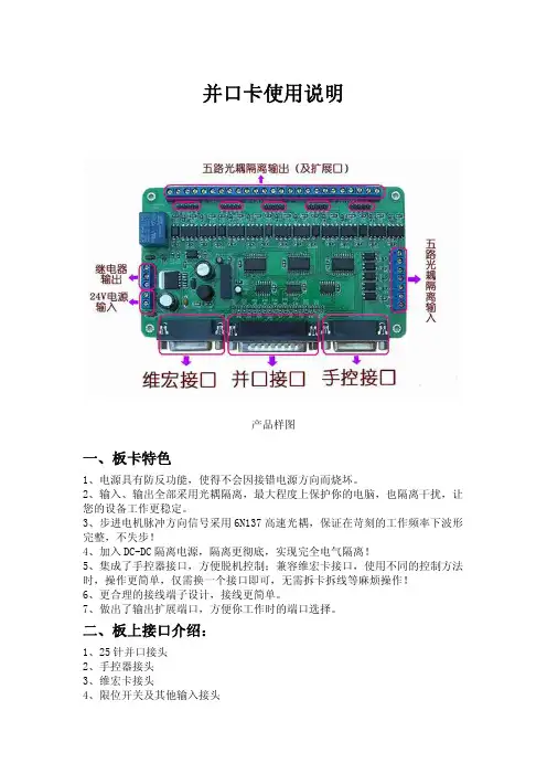
并口卡使用说明产品样图一、板卡特色1、电源具有防反功能,使得不会因接错电源方向而烧坏。
2、输入、输出全部采用光耦隔离,最大程度上保护你的电脑,也隔离干扰,让您的设备工作更稳定。
3、步进电机脉冲方向信号采用6N137高速光耦,保证在苛刻的工作频率下波形完整,不失步!4、加入DC-DC隔离电源,隔离更彻底,实现完全电气隔离!5、集成了手控器接口,方便脱机控制;兼容维宏卡接口,使用不同的控制方法时,操作更简单,仅需换一个接口即可,无需拆卡拆线等麻烦操作!6、更合理的接线端子设计,接线更简单。
7、做出了输出扩展端口,方便你工作时的端口选择。
二、板上接口介绍:1、25针并口接头2、手控器接头3、维宏卡接头4、限位开关及其他输入接头5、五路步进电机输出接头6、主轴继电器输出接头7、24V电源接头三、详细接线介绍:1、并口卡与驱动连线:可以采用共阴或共阳接法,配合我们的步进电机驱动器,接线方法可参照我们的步进电机驱动器接线方法,5路相同:(1)共阳极接法:分别将驱动CP+,U/D+,EN+连接到并口卡的5V电源上(V-X),驱动CP-接并口卡CP,驱动DIR-接并口卡DIR,EN-接并口卡EN。
(2)共阴极接法:分别将驱动CP-,U/D-,EN-连接到并口卡的5V电源地上(GND),驱动CP+接并口卡CP,驱动DIR+接并口卡DIR,EN+接并口卡EN。
注:EN端可不接,EN有效时电机转子处于自由状态(脱机状态),这时可以手动转动电机转轴,做适合您的调节。
手动调节完成后,再将EN设为无效状态,以继续自动控制。
2、五路输入端接法:用户可外接限位开关,急停信号等!需外接电源,将开关接在电源地与输入点之间,开关按下或限位开关触发,将输入信号与地导通,内部触发接收到的输入信号,并通过并口传至电脑。
内部连线图3、继电器输出接线方法:板卡将继电器的公共COM端与常开常闭端都引出,用户可根据自己需要接入!4、控制接口:本板卡集成了手控设备,PC并口设备,维宏运动控制卡三种接入,接头分别是15针并口母头(手控、维宏),25并口公头(电脑MACH软件)。
3轴驱动板说明书一、该版本具有以下功能和特点1、具备3路0—2.5A可调电流额定输出步进驱动;2、标准并口接口,支持MACH2、KCAM4等系列软件;3、带光电隔离及DCDC电源隔离,充分保护你的电脑及设备;4、带限位或急停接口;5、支持3种工作模式——混合模式、快速模式、慢速模式;6、支持四种细分选择——1、1/2、1/4、1/8;7、12—36V单电源输入使用开关电源芯片作为5V供电,稳定发热小;8、采用555半流;9、带2两路继电器输出控制。
10、带第4轴扩展控制接口该板外观结构图如下,接口及其定义1、并口控制的25个脚定义如下:DB25控制引脚(PIN) 在驱动板上引脚的作用1 所有轴使能2 STEPX3 DIRX4 STEPY5 DIRY6 STEPZ7 DIRZ8 STEPA- 通扩展控制接口19 DIRA- 通扩展控制接口310 LIMIT-111 LIMIT-212 LIMIT-313 LIMIT-414 第1路继电器控制15 悬空16 第2路继电器控制17-25 GND并口扩展接口,引脚定义同以上表格PP1-PP16对应并口的1-16如图所示:维宏卡接口,接口定义参考并口定义表2、电源请接12~24V 4A以上开关电源,接到图上标明电源输入的接口。
电源正负板上已经做了说明。
3、手控接口定义驱动板J6左上角方框标志为1脚如图1、2接单刀开关,导通后发送脉冲信号( PP2-STEPX)3、4、5、6 接双刀开关,导通后发送脉冲同时改变方向(PP3-DIRX) 同理,7、8接单刀开关,导通后发送脉冲信号(PP4-STEPY)9、10、11、12 接双刀开关,导通后发送脉冲同时改变方向(PP5-DIRY)13、14接单刀开关,导通后发送脉冲信号(PP2-STEPZ)15、16、17、18 接双刀开关,导通后发送脉冲同时改变方向(PP3-DIRZ) 4、限位接口定义驱动板上JP2位置,左上角为1,原理图与PCB图对照5、第四轴扩展控制接口定义:观察驱动板上10针插座有▽符号所指向即为Pin12、4-控制两路继电器5-EN+ 6-EN- 7-DIR+ 8-DIR- 9 STEP+ 10-STEP- 细分设置对拨码开关上的1、2两路,S2/S1:ON/ON——1 ;ON/OF——1/2 ;OF/ON——1/4 ;OF/OF——1/8 ;拨码2 拨码1 细分模式ON ON 1OF ON 1/2ON OF 1/4OFF OFF 1/8工作模式选择(PFD—用于控制电流衰减模式)对拨码开关上的3、4两路,S4/S3:ON/ON——混合工作模式;ON/OF——快速工作模式;OF/ON——慢速工作模式;OF/OF——拨码1 拨码2 工作模式ON ON 混合衰减OF ON 快衰减ON OF 慢衰减OFF OFF。
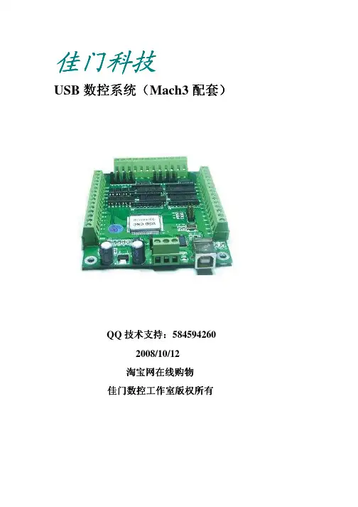
佳门科技佳门科技配套))USB数控系统数控系统((Mach3配套技术支持::584594260QQ技术支持2008/10/12淘宝网在线购物佳门数控工作室版权所有Mach3安装说明安装说明::1.本控制卡使用在Mach3 R2.60-2.63版本,3.0的版本现在还不支持,运用本卡控制加工是纯软件并口控制是无法比拟的。
不掉步,不死机,对电脑要求低,最高可运行100KHZ频率。
2.Mach3安装到最后不要选并口驱动程序安装,选了也没关系,只是影响你的电脑速度。
Mach3软件安装后不用重新启动电脑,不会出现蓝屏死机现像。
先不要把控制卡通电,拔掉USB连线。
进行下一步。
3.点击“Mach3 CNC USB 驱动1.2”安装图标进行USB驱动安装,4. 点击“下一步”选择Mach3软件安装在的文件夹路径,请要选择正确Mach3软件安装路径,否则接下来的都是错误的。
(不能完成控制)5.Mach3 CNC USB 驱动安装完后这时就可以把控制卡上电,通电正常后插上USB线,Windows提示发现找到新硬件。
按照提示选“从列表或指定位置安装”进行下一步。
6.请要选择Mach3软件安装的路径,,进行下一步。
安装完成后可以在电脑“设备管理器”中找到驱动设备,如下图:B驱动安装好后,就可以运行Mach3软件了,在第一次运行时会跳出选择设备对话框,请选择“佳门USB控制卡Ver1.1”,在下面点”以后不提示”这时您就可以使用本卡了。
控制卡控制卡总总接线图电源输入直流+5V ,如果要输出模拟量0-10V 要接+12V 的输入,左边的端子为输出,右边的端子为输入,下部的端子为轴脉冲输出,全部端子输入光耦隔离,轴脉冲输出为差动输出,可以控制交流伺服驱动。
输出端驱动能力500mA ,可以接直流24V 继电器,12个输入,8个输出。
总耗电量900Ma.下图是控制卡的总接线图电源输入有极性错误保护及过电流保护,在未连接控制卡时请确认您的电源,不符合规格的电源有可能把板卡烧毁。

Mach 3 Based CNC Control KitsNow available from Ajax CNC - Simple Mach 3 based plug and play CNC Control Kits starting at only $995! Save time and money and do it yourself with a kit specifically designed for you to connect your own PC with Mach3 CNC software via a standard Ethernet cable, for full CNC capability.In this document:•Kit descriptions and photos• Kit diagrams• Pricing•Frequently Asked QuestionsTwo basic kit configurations are available:•Mach3 CNC Kit with 3-Axis DC Servo Drive & PLC•Mach3 CNC Kit For 3rd Party Drives With PLCFor more information regarding AjaxCNC’s Mach CNC kits, or questions regarding the information contained in this document, please contact:sales@AjaxCNC159 Gates Road, Suite AHoward, PA 16841814-360-0279Or visit Mach3 CNC Kit with 3-Axis DC Servo Drive & PLCThis kit includes the major components you need for a fully capable DC CNC system, perfect for the do-it-yourselfer who wants to save money and still have all the features of a more expensive off-the-shelf system. AjaxCNC has bundled together a fast, reliable DSP-based CNC CPU card (our "MPU11"), with a 15 amp 3-axis servo drive and PLC combo (our "DC3IO"), into a dead simple plug-and-play system optimized for use with Mach3 software. Not only that, we've taken all the work out of configuring your system: coolant, lube, spindle control, limits, and more have dedicated connections and are pre-programmed and ready to run.Shown above is a depiction of a typical setup for this kit - only a few simple connections are required, and all components are powered by standard household 110VAC. Install Mach3 software and AjaxCNC's included plugin on your PC, connect it via Ethernet to the CNC CPU card, plug in your motors and switches, and you're essentially ready to run!Need more options or expanded PLC I/O? Want to add a 4th axis, digitizing probe, tool length setter, MPG handwheel, or operators control panel? No problem! Our kits are expandable,upgradeable, and have the flexibility to meet nearly any application.Above is a more detailed diagram and overview of how our kit components work together in a complete CNC system. Please note that motors, cables, Mach3 software and some other depicted components are sold separately (or you may supply or reuse your own).Our Mach3 kits solve a major problem of other PC-based systems: we provide a dedicated CNC CPU card (our "MPU11"). Other systems rely on your PC's internal processor to command servo drives -- any "hiccups" or problems on your PC while running a job are instantly transferred to the drives on these "hobby" systems. AjaxCNC's Mach3 kits also feature two-way Ethernet communication, so that Mach3 on your PC always receives position feedback and never has to guess at the position of the machine (like in other systems without two-wayEthernet communication).MPU11 Motion Controller•Fast Ethernet based communication with any capable PC running Mach 3 CNC software •DSP-based motion control• 6 encoder inputs onboard•MPG, probe, and jog panel/pendant connections•Fiber optic connection•Multi-axis homing and jogging•Includes power supplyDC3IO 3 Axis DC Servo Drive & PLC•3-Axis 15amp closed loop DC servo drives•PLC 30 In / 31 Out onboard (expandable to 240 I/O)•Pre-programmed I/O for:- Programmable Spindle Speed- Programmable Coolant•Limit switches can be wired directly with no further software configuration needed •Auto homing to limit switches or encoder index pulse•Auto lube controlThis kit includes power supplies and connectors for the above components and 5' fiber optic cables for communication. Ready-to-run servo motors with encoders are sold separately on . Mach3 software is available directly from Artsoft & Newfangled Solutions LLC, and is not included in pricing below.Limited Time Offer:Mach3 CNC Kit With 3-Axis DC Servo Drive & PLC:$1195.00Mach3 CNC Kit for 3rd Party Drives With PLCThis kit includes the major components you need for a fully capable CNC system (AC or DC), perfect for the do-it-yourselfer who wants to save money and supply (or re-use) their own motors and drives. AjaxCNC has bundled together a fast, reliable DSP-based CNC CPU card (our "MPU11"), with a Drive Interface and PLC combo board (our "GPIO4D"), into a dead simple plug-and-play system optimized for use with Mach3 software.This system will communicate with any -10v to +10v drives.Shown above is a depiction of a typical setup for this kit - only a few simple connections are required, and all components are powered by standard household 110VAC. Install Mach3 software and AjaxCNC's included plugin on your PC, connect it via Ethernet to the CNC CPU card, plug in your drives and motors, and you're essentially ready to run!Need more options or expanded PLC I/O? Want to add a 4th axis, digitizing probe, tool length setter, MPG handwheel, or operators control panel? No problem! Our kits are expandable,upgradeable, and have the flexibility to meet nearly any application.Above is a more detailed diagram and overview of how our kit components work together in a complete CNC system. Please note that motors, drives, cables, Mach3 software and some other depicted components are sold separately (or you may supply or reuse your own).Our Mach3 kits solve a major problem of other PC-based systems: we provide a dedicated CNC CPU card (our "MPU11"). Other systems rely on your PC's internal processor to command servo drives -- any "hiccups" or problems on your PC while running a job are instantly transferred to the drives on these "hobby" systems. AjaxCNC's Mach3 kits also feature two-way Ethernet communication, so that Mach3 on your PC always receives position feedback and never has to guess at the position of the machine (like in other systems without two-wayEthernet communication).MPU11 Motion Controller•Fast Ethernet based communication with any capable PC running Mach 3 CNC software•DSP-based motion control• 6 encoder inputs onboard•MPG, probe, and jog panel/pendant connections•Fiber optic connection•Multi-axis homing and jogging•Includes power supplyGPIO4D 3rd Party Drive Interface & PLC•Enables communication with up to four 3rd party servo drives•16 bit analog to servo drives -10v to +10v•12 bit analog to spindle inverter 0 to 10v•16 general purpose I/O onboard (expandable to 240 I/O)This kit includes power supplies and connectors for the above components and 5' fiber optic cables for communication. Ready-to-run servo motors with encoders are sold separately on . Mach3 software is available directly from Artsoft & Newfangled Solutions LLC, and is not included in pricing below.Limited Time Offer:Mach3 CNC Kit For 3rd Party Drives With PLC:$995.00Mach 3 Based CNC Control Kits - Frequently Asked QuestionsHow are AjaxCNC's Mach kits different from other competing products?•AjaxCNC provides a dedicated, stand-alone digital signal processor, just like "real" CNC systems use. Other competing Mach systems rely on your PC's internal processor,which often results in hesitant or unreliable motion any time your PC "hiccups" during a job.•Our kits utilize an Ethernet connection for true two-way communication – this enables Mach software to receive real-time position feedback, instead of simply guessing at and assuming the position of your machine.•AjaxCNC provides pre-configured PLC functions for items such as limits and coolant wherever possible so you can be up and running quickly.•Price – because we design and manufacture our components from the ground up, we can provide feature-rich CNC kits that are more affordable for the do-it-yourselfer.Which of the two kit configurations is right for my project?Please refer to the chart below:Kit With 3-Axis DC Servo Drive & PLC Kit For 3rd Party DrivesWith PLCIntroductory Price $1195 USD $995 USD Servo motor type DC AC or DC Servo motor size Up to 40 in lb Unlimited Number of axes (standard) 3 4 Number of axes (expandable to)* 6 4 Number of encoder or scale inputs 6 6 General purpose I/O (standard) 30 In / 31 Out 16 In / 16 Out General purpose I/O (expandable to)* 240 In / 240 Out 240 In / 240 Out Included servo drivesPreconfigured I/OSpindle controlAvailable operator's control panel/pendant*Available digitizing touch probe*Available MPG (manual pulse generator) handwheel*Available auto tool length setter** Expandable features and accessories may require purchase of additional components. Prices and specifications are subject to change. Please refer to for the latest pricing and information.Do AjaxCNC's control kits accept Step and Direction?AjaxCNC's kits replace and greatly improve on old "step and direction" parallel port systems. With true two-way Ethernet communication we provide the hardware required to eliminate "missed steps" and position errors.In step and direction systems, there is no position feedback to your CNC software – the software can only command the movement and assume that the machine has responded accurately. The position displayed on the digital readout will always be an assumption – small errors and missed steps can compound over a job and waste material and time.With our Ethernet-based communication, your CNC software (Mach3) is constantly receiving real position feedback during a job – the software commands a movement, the machine responds, and the software instantly gets feedback and displays the true position of the machine. What would be position errors in old step and direction systems are automatically corrected, before the next move is attempted.What are the system requirements for the PC that I will need?Generally speaking, any modern Windows computer that is capable of running Mach3 software will be adequate. (You should check the Mach3 software and hardware requirements.) Also note that because AjaxCNC's kits utilize an Ethernet connection to your PC, you may wish to obtain a second network/Ethernet card for simultaneous networking purposes.What are the power requirements of the kit components? Will AjaxCNC's Mach kits work outside of the USA?AjaxCNC Mach3 kit components include power supplies for logic circuitry which can accept 110 or 220 VAC. Standard 110v power cords with 3-prong grounded plugs are included by default. See chart below:Component Power RequirementMPU11 MotionControllerIncluded power supply accepts 85 to 260 VACDC3IOB Servo Drive & PLC Includes a switchable power supply with 110 and 220 VAC settings for the logic circuitry. Incoming motor voltage supply requirement is 20v to 120v DC.*GPIO4D DriveInterface & PLCIncluded power supply accepts 85 to 260 VAC*AC to DC power supply transformer kits and components are available through.What drives will work with the "3rd party drive kit"?The kit for 3rd party drives will command any servo drive capable of accepting -10 to +10v.Do you have servo motors and encoders for sale?Yes, AjaxCNC does sell a range of servo motors with encoders pre-installed and ready to run! Visit for sizes and more information.What accessories are available for use with AjaxCNC's Mach kits?Our Mach kits have been designed to support our digitizing touch probe, manual pulse generator (MPG) handwheel, operators control panel/pendant, and automatic tool length setter. These items as well as other components and accessories are available from the CNC accessories page of .Copyright © 2009 AjaxCNC. All rights reserved.Prices, features, products and specifications contained in this document are subject to change. Please refer to for the latest information and pricing.。
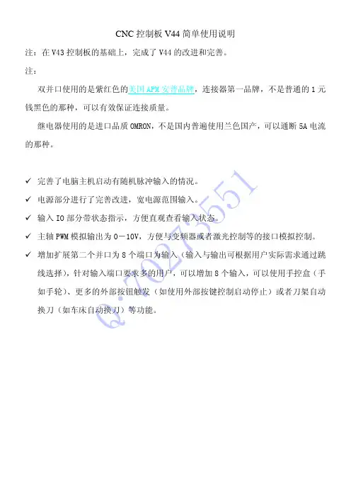
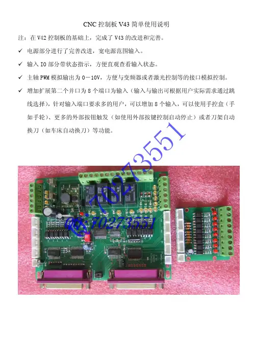
Q :70273551CNC 控制板V44简单使用说明注:在V43控制板的基础上,完成了V44的改进和完善。
注:双并口使用的是紫红色的美国APM 安普品牌,连接器第一品牌,不是普通的1元钱黑色的那种,可以有效保证连接质量。
继电器使用的是进口品质OMRON,不是国内普遍使用兰色国产,可以通断5A 电流的那种。
9 完善了电脑主机启动有随机脉冲输入的情况。
9 电源部分进行了完善改进,宽电源范围输入。
9 输入IO 部分带状态指示,方便直观查看输入状态。
9 主轴PWM 模拟输出为0-10V,方便与变频器或者激光控制等的接口模拟控制。
9 增加扩展第二个并口为8个端口为输入(输入与输出可根据用户实际需求通过跳线选择),针对输入端口要求多的用户,可以增加8个输入,可以使用手控盒(手如手轮)、更多的外部按钮触发(如使用外部按键控制启动停止)或者刀架自动换刀(如车床自动换刀)等功能。
Q :70273551主板Q :70273551功能简介1、功能强大,同时使用两个接口,把所有的功能都扩展出来,也可只使用一个并口,但功能有限。
2、所有的输入信号都经过光电隔离,不用担心强电信号和干扰信号进入电脑板卡上,安全保证。
3、芯片和大部分元件使用SMD 贴片元件,提升可靠性。
所有的输入信号都经过处理后才进入电脑,不怕干扰和误动作。
4、 输入信号及电源使用规范的工业24V 电源,或者使用18-24V 宽电源均可。
5、输出控制使用工业PLC 内使用的进口品质12V 或者24V 继电器,有效保证工作正常。
6、 轴控制信号可以连接步进驱动或者伺服驱动,方便不同用户的实际需求。
7、最多可以控制7轴:3个方向轴3个附加扩展轴,1个主轴 可以通过手动控制主轴:用继电器或电流接触器控制电机的启动(顺时针或逆时针)和停止。
通过分步或直接脉冲控制电机(电机为伺服电机)。
通过脉冲宽度调制信号控制电机(如PWM输入控制的变频器)。
D.可以输出模拟电压0-10V,可以通过S命令直接控制变频器。
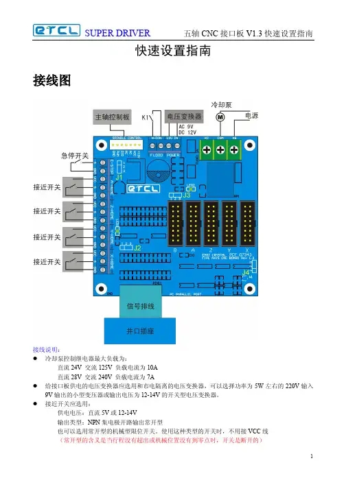
快速设置指南接线图接线说明:l冷却泵控制继电器最大负载为:直流24V 交流125V 负载电流为10A直流28V 交流240V 负载电流为7Al给接口板供电的电压变换器应选用和市电隔离的电压变换器,可以选择功率为5W左右的220V输入9V输出的小型变压器或输出电压为12-14V的开关型电压变换器。
l接近开关应选用:供电电压:直流5V或12-14V输出类型:NPN集电极开路输出常开型也可以选用常开型的机械型限位开关。
使用这种类型的开关时,不用接VCC线(常开型的含义是当行程没有超出或机械位置没有到零点时,开关是断开的)板上跳线说明:l J1接近开关供电电压选择。
当1脚与2脚相联时,接近开关的供电电压为12-14V(与接口板的供电电压相同)当2脚与3脚相联时,接近开关的供电电压为5V。
l J2CHARGE PUMP功能设定。
当1脚与2脚相联时,该功能使能。
当2脚与3脚相联时不使用该功能。
(CHARGE PUMP为一个系统的安全功能,当上位机软件没有正常工作或处于REST状态时,所有输出是关闭的。
使用这个功能,可以消除上位机没有工作时主轴乱转或冷却泵打开等情况。
)l J3并口3脚信号作用选择。
当1脚与2脚相联时,3脚信号作为B轴的脉冲信号。
当2脚与3脚相联时作为冷却泵的控制信号。
(当使用第五轴时,需要将该跳线跳到1脚和2脚,同时冷却泵将由外接开关K1手动控制,同时上位机软件要作相应的设置)l J4并口9脚信号作用选择,当1脚与2脚相联时,9脚信号作为CHARGE PUMP控制信号。
当2脚与3脚相联时作为B轴的方向信号。
(当使用第五轴时,需要将该跳线2脚与3脚相联。
并将J2跳到CHARGR PUMP不使用状态。
同时上位机软件要作相应的设置)板上指示灯说明:l LED1CHARGE PUMP状态指示,不发光时所有输出是关闭的,所有控制信号将没有输出,发光时输出信号将开启,并由上位机软件控制。
l LED2电源指示,当电源接通时LED2应发光。
MACH3接口板使用说明1.电源接线:将接口板上的电源正负极分别与电源的正负极相连,确保接口板正常供电。
2.步进电机接线:将步进电机的A+,A-,B+和B-分别连接到对应的接口板上,接线时要注意极性的正确性,以免损坏电机。
3.限位开关接线:将限位开关的信号接线连接到接口板的对应引脚上,确保在机床运行时能够准确检测到限位信号。
4.运动控制卡接线:将接口板通过并口线或者USB线连接到电脑上,确保电脑能够正常识别接口板并进行通信。
接线完成后,还需要进行一些参数设置才能正常使用MACH3接口板:1.参考点设置:首先需要设置机床的参考点,通过手动调整机床到一个基准位置,然后在MACH3软件的参考点设置界面进行设置。
2.步进电机设置:根据实际步进电机的参数,设置步进电机的步进角度和细分数。
步进角度一般为1.8度,细分数根据精度要求来确定。
3.速度和加速度设置:根据实际需求,设置机床的运行速度和加速度。
速度和加速度设置过高可能导致电机无法正常工作,同时也会影响机床的精度。
4.输入和输出设置:根据实际需要,设置数字输入和输出的功能和映射关系。
可以通过接口板上的输入和输出端口实现一些辅助功能。
5.状态检测设置:设置MACH3软件对机床状态的检测方式,可以设置错误报警和状态显示等功能。
在正常使用MACH3接口板时,可能会遇到一些常见问题,下面是一些常见问题的解决方法:1.机床无法运动:首先检查步进电机的接线是否正确,以及步进电机的参数设置是否符合实际情况。
其次检查接口板的供电情况,确保接口板正常供电。
2.运动不稳定或者步进电机发热:这可能是电机供电不稳定或者过流导致的问题,可以检查电源和电机的额定电压和电流是否匹配,同时检查接口板的供电情况。
3.MACH3软件无法识别接口板:首先检查接口板的连接是否正常,确保并口线或USB线连接稳定。
其次检查电脑的并口或USB驱动是否正确安装。
4.限位开关无法正常工作:检查限位开关的信号线是否接触良好,以及限位开关的参数设置是否正确。
Mach3英文版是用注册文件注册,中文版是用加密狗方式。
英文版只要有一个注册文件到处可以用,这个注册文件网上有的下载,去年的0day里出来过的。
中文版只能用狗,这狗是用的彩虹公司的精灵狗,空狗35块钱一只,硬件复制的我没见过。
所以:只要到官方下载最新的英文版安装文件,装上,然后下载对应的英文版的汉化文件覆盖,把注册文件放到mach3安装目录下,装个中文版的把里面的界面文件复制过来,这样就可以用的跟正版一样了。
不要相信人家说没狗会丢步这么一说,这是人家想多卖几只狗。
Mach 3 中文版软件下载:/ChineseMach/CHMach3.html/Mach3Chinese.html/gq/gycx.asp?id=27483/artsoft/downloads/downloads.htm在自製CNC 雕刻机方面,MACH3恐怕是功能最好,使用最多的软体了,经过一段时间的摸索,整理了一份使用教程,与大家分享,正在整理一份详细教程,完成后会分享﹗我正在试用的MACH3 1.90和六轴界面第一部分先介绍最基本的设置,以后会不断完善直接双击桌面图标,打开程式六轴主界面软体初始设置机器人,雕刻软体初始设置都在这裡初始设置第一项单位RobotCNC应该根据原始加工代码定义的单位确定端口设置是MACH3最基本最重要的设置项目,应该认真阅读自己的界面板及驱动板说明书中有关端口定义的内容后,再详细设置﹗并口选择和传输速度一般都只使用一个并口,默认即可,其他参数要根据界面板设置。
各轴电机端口和针脚设置step pin#︰步进信号,dir pin#︰方向信号,step port ,dir port 各针脚所在端口。
输入端口设置︰根据界面板定义分发的并口针脚,设置各轴的限位开关、原点以及DAO输入。
在输入端设定Estop--紧停开关。
根据界面板定义的紧停开关设置相应针脚,如没有连接开关,可在界面板上短接,否则软体紧停按钮可能一直会闪烁--因為它会认為是紧停开关没有复位﹗﹗输出设置,根据界面板定义设置软体信号输出针脚--控制主轴、冷却、切削帮浦等的起停运转软体限位设置从动轴定义系统热键设置这裡设置步进电机的脉波,速度参数,关键是要根据自己的驱动和电机的参数情况,逐步调试设置到最佳参数﹗设置脉冲数,这要根据你丝杆螺距,驱动板细分数,电机角度来设置多少个脉冲走1毫米,并且可以设置电机起停加速参数,记住每个轴设置完成后都要储存一下...。
MACH3接口板BL-MACH-V1.1使用说明功能特点:1、完全支持MACH3及其它支持并口控制的电脑软件。
2、USB供电和外围供电相分离,保障电脑安全。
3、外围宽电压输入,12-24V,并有防反接功能。
4、所有输入信号全部经光藕隔离,可接急停、对刀、限位等,保障电脑安全。
5、一路继电器输出端口,可控制主轴开关。
输出口为P17口。
6、一路经光耦隔离的0-10V模拟电压输出,可以控制具有相应模拟接口的变频器,控制主轴转速。
输出口为P1口。
7、开放所有17个端口,可接带光耦的驱动器,可控制5轴步进电机。
8、P1作为PWM输出,可控制带光耦输入的主轴调速器。
9、可接共阴或共阳、输入电平为5V的驱动器。
10、板印所有端口名称、一目了然。
Mach3接口板BL-MACH-V1.1使用说明整体功能、接线图:GNDP10–急停P11–对刀PX 12–P Y 13–P Z 15–P X 2-脉冲P X 3-方向-P Y 4-脉冲-P Y 5-方向P Z 6-脉冲P Z 7-方向P A 8-脉冲P A 9-方向P14-总使能P B 16-脉冲P B 17-方向/继电器P PWM1-PCGND(共阴端)PC V 5(共阳端)PC V 5(共阳端)注意:以下的设置是按接口板与驱动器是采用共阳的接线方式来设置的。
MACH3软件的相关设置:一、检查MACH3驱动是否正常安装:注意:“Mach3 Driver ”不能有“!”或“?”。
二、软件设置:1、公英制选择。
设置单位:在“设置”里的“公/英制选择” 选公制毫米Mach3接口板BL-MACH-V1.1使用说明2、端口/针脚(1)、端口设置和轴向选择:注意--设置好后点应用(2)、电机输出:如图设置好后点应用。
注意:步进电机的转向和接线有关,如果方向不对,可以调整上图的“Dir LowActive”。
(3)、输入信号:如图设置,设定后点应用。
Mach3接口板BL-MACH-V1.1使用说明(4)、输出信号:如图设置,设定后点应用。
CNC MACH 3 in&out-put port extension board MODIO_II NEWFeatures:1、it is very easy to setup the extension IO input and output port expeciallyfor the Mach 3 control2、16-wires optical isolated input ( 2-wires are high-speed IO)3、12-wires optical isolated input ,4-wires relay output can control theexternal equipments4、The communication port is MODBUS slavestation , 1 RS232communication port by setting up the jumper , this RS232 port can be used as RS485 or USB port5. 3 wires analog quantity input port can connect the external sensor or extention input port接口定义Jumper :1、power jumperUSB to RS232 power supply choiceJP1 JP2 L:external power supply R:USB power supply 2、USB choice jumperUSB communication function ENUp: Enable USB communication Down:Disable USB communication,USB just provide the power3、communication port choice jumperUSB: use USB communication portRS232: use RS232 communication portRS485: use RS485 communication portmunication connecting portUSB connector can supply the power to IO board , it corresponds to the PC communication port NRS232 connector ,uses DB9 serial port cable to connect the PC , it corresponds to the PC commnunication port COM0RS485 connector ,it corresponds to the PC commnunication port COM0Relay connecting portIO-PORT can be connected to the relay OI board , to change the output function to RelayInput connecting portInput port has 8 digits , IN1-IN16, GND is the ground connection on the board, VCOM is the input coupling power supply port, when it is the 5V power, you can not connect it, but when larger than 5V, you have to put a current-limiting resistance on the IN port. when 5V is the external power supply port and using USB power supply , please do not connect this , using the external power , the jumper must setup as external power supply.By the input port, we can connect many kinds of the sensor and the switch , to realize a lot of functions.connect to the mechanical switchesconnect to the sensorproximity sensor optical sensorOutput portoutput port has 8 digits , OUT1-OUT8, GND is the ground connection on the board, COM + is the output coupling power supply port, you do not need to connect it, COM- is the output coupling -. 5V power is as the same as the input 5V.OUTA,8 are the relay and COM normal open and normal closed connecters, Vin is the power input 6-12VUse RS232 or RS482 communication , Mach 3 can control the COM1 by the MODBUS .If use the RS485, you have to install a 232-485 port on the PC serial port. By using the RS485 , you can control the lathe in a long distance about 1200m.ModBus InputOutput Supported setupwhen setup the MACH 3 in&out put port,choose ModBus InputOutput Supported .Function Cfg’s->Setup serial ModBus controlHere are the steps from 1 to 10, please setup step by step.1、Serial port number, the NO.1 port usually connects to the RS232or the RS485. We can get the USB port NO. by seeing which USB equipment is the default Prolifice USB-to-Serial Comm Port, the test port No. is 6.2、38400 data transfer frenquency is 384003、the transfer mode of the Serial port4、the time is between 50-100ms5、choose input6、ModBus equipment NO.7、ModBus beginning address8、input port NO.9、choose the discrete10、choose the coils outputChoose Test ModBus,as belowsFile the communication info and Open the serial port equipment。
雕刻机接口板使用说明目录一、雕刻机接口板功能简介: (3)二、电气接线图: (3)三、接口板和驱动器的连接方法: (4)四、信号输入接口的连接方法: (4)五、继电器接口的使用: (5)六、并口的25针引脚输出定义: (5)七、Mach3软件的设置和使用方法: (6)7.1 Mach3的启动: (6)7.2 Mach3软件的端口设置: (7)7.3 限位开关的mach3设置: (11)7.4电机调试: (12)7.5 G代码的运行: (14)7.6 如何使用MACH3的手控界面: (16)八、联系我们: (17)一、雕刻机接口板功能简介:1、同时接5块步进电机驱动板器,控制5个步进电机运转2、带四路限位开关接口,可以接限位开关和急停开关,复位,对刀开关等。
3、带继电器控制,可控制雕刻机主轴电机的转动与不转动。
4、工作电压DC5V5、支持mach3软件。
二、电气接线图:三、接口板和驱动器的连接方法:X、Y、Z、4、5轴接口连接驱动板示意图:四、信号输入接口的连接方法:信号输入接口可以接限位开关和急停开关,对刀等,下图都以限位开关示意,具体的使用可以参考mach3中文教程:五、继电器接口的使用:继电器可以控制主轴的启动和停止,要使用该继电器,首先要对软件进行设置,软件的设置在后面章节中会提到。
在使用时即可通过代码控制继电器的吸合和释放,以此控制主轴的启动和停止。
六、并口的25针引脚输出定义:图6.1 并口接口并口简介:电脑的并口是一个25针D型凹槽连接器,图6.1所示为从电脑后方观看得并口插槽,箭头所指的方向为信息流相对电脑的流动方向,如标号为10-13的脚针是对向脑输入数据的。
接口板并口输出信号定义:七、Mach3软件的设置和使用方法:说明:这里将对mach3的基本设置进行讲解,对于mach3的设置是一个复杂的过程,我们这里的介绍主要是针对我们的驱动板进行,让您能够使电机正常转动,对于一些复杂的设置请您参考mach3的使用手册,那里有非常详细和专业的讲解。