CCNA实验手册(含综合实验)
- 格式:pdf
- 大小:1.82 MB
- 文档页数:43


一、实验目的学习使用ACL(访问控制列表)来控制网络访问。
二、实验设备路由器三台,pc两台,连线若干三、实验内容1、按上图连接好网络,设置好主机名。
2、设置主机IP:A:f0:192.168.1.1/24,s0:200.1.1.1/30B: s0:200.1.2.1/30;s1:200.1.1.2/30C:s1:200.1.2.2/30;f0:192.168.2.1/24Ftp server:192.168.1.2/24 gateway:192.168.1.1/24Web server:192.168.2.2/24 gateway:192.168.2.1/24咨询电话:咨询:实验目的:熟悉RIP协议的配置方法,和使用CISCO发现协议访问其他路由器。
实验要求:熟练配置RIP协议,掌握RIP v1和RIPv2的区别与特点。
实验设备:三台CISCO1721路由器,两台PC,交叉双绞线两根,Serial连线两根。
实验步骤:1、设置三台路由器的主机名为A,B,C。
将pc1与A的以太网口相连,pc2与C的以太网口相连。
将A的S0口与B的S1口相连,将B的S0口与C的S1口相连。
咨询电话:咨询:Pc1 Pc21、按上图将pc、交换机和路由器连接好。
2、在特权模式下设置子网掩码的格式,用term ip netmask-format命令。
命令格式为:router#term ip bitcount | decimal | hexadecimal3、为pc和路由器设置IP。
Pc1---192.168.1.1/24,网关为:192.168.1.2,A:f0---192.168.1.2/24,S0---192.168.3.1/24。
B:S1---192.168.3.2/24,S0---192.168.4.1/24。
C:S1---192.168.4.2/24,f0---192.168.2.2/24。
Pc2---192.168.2.1/24,网关为192.168.2.2。

静态路由实验实验1:基本静态路由配置实验需求: R1 能通访问(ping通)R3实验配置步骤:R1的基本配置:--- System Configuration Dialog ---Continue with configuration dialog? [yes/no]: n!Router>enable ----进入特权模式Router#config t ---进入全局配置模式Router(config)#hostname R1 ---修改系统的名字R1(config)#interface f0/0 ----进入到接口配置下R1(config-if)#ip address 12.1.1.1 255.255.255.0 ----接口配置地址R1(config-if)#no shutdown ---开启接口R2的基本配置:--- System Configuration Dialog ---Continue with configuration dialog? [yes/no]: n!Router>enable ----进入特权模式Router#config t ---进入全局配置模式Router(config)#hostname R2 ---修改系统的名字R2(config)#interface f0/0 ----进入到接口配置下R2(config-if)#ip address 12.1.1.2 255.255.255.0 ----接口配置地址R2(config-if)#no shutdown ---开启接口!R2(config)#interface f0/1 ----进入到接口配置下R2(config-if)#ip address 23.1.1.2 255.255.255.0 ----接口配置地址R2(config-if)#no shutdown ---开启接口R3的基本配置:--- System Configuration Dialog ---Continue with configuration dialog? [yes/no]: n!Router>enable ----进入特权模式Router#config t ---进入全局配置模式Router(config)#hostname R3 ---修改系统的名字R1(config)#interface f0/1 ----进入到接口配置下R1(config-if)#ip address 23.1.1.3 255.255.255.0 ----接口配置地址R1(config-if)#no shutdown ---开启接口R1上配置去往23.1.1.0/24 网段的静态路由R1(config)#ip route 23.1.1.0 255.255.255.0 12.1.1.2!R1#show ip route ---查看路由表12.0.0.0/24 is subnetted, 1 subnetsC 12.1.1.0 is directly connected, FastEthernet0/023.0.0.0/24 is subnetted, 1 subnetsS 23.1.1.0 [1/0] via 12.1.1.2R3上配置去往12.1.1.0/24网段的静态路由R3(config)#ip route 12.1.1.0 255.255.255.0 23.1.1.2!R3(config)#do sh ip routeGateway of last resort is not set12.0.0.0/24 is subnetted, 1 subnetsS 12.1.1.0 [1/0] via 23.1.1.223.0.0.0/24 is subnetted, 1 subnetsC 23.1.1.0 is directly connected, FastEthernet0/1测试R1-到-R3的通信R1#ping 23.1.1.3Type escape sequence to abort.Sending 5, 100-byte ICMP Echos to 23.1.1.3, timeout is 2 seconds: ..!!!备注:前面丢掉了2个包,说明再做ARP地址解析的时候丢弃的。

S1和S2两台交换机之间有三条链路相连,F0/4,F0/5,F0/6,F0/4和F0/5组成一组以太通道,S1上把连接PC2的端口设置为access vlan 2S2上把连接PC3的端口设置为access vlan 3,把连接DHCP服务器的端口设置为access vlan1实验要求:1.以太通道走vlan2的数据,另一条通道走vlan3的数据,同时vlan信息进行同步2.R1作为单臂路由器,用于PC2属于的vlan2和PC3属于的vlan3交换数据;S2连接的DHCP服务器,作为PC2和PC3的DHCP服务器1.S1和S2之间的三条链路,F0/4和F0/5形成以太通道,以太通道走vlan2的数据,F0/6走vlan3的数据;S1和S2之间的vlan信息要进行同步,其实只需要把两台交换机之间的链路设置为trunk,同时把两台交换机的vtp domain设置为一样2.R1作为单臂路由器,这个需要在R1连接S1的端口上进行相关操作(进入子端口,设置子端口的封装格式,设置子端口属于哪个vlan)DHCP作为PC2和PC3的DHCP服务器,并且连接S2的端口属于vlan1,这个需要在R1的主接口上设置vlan1的网关,同时需要在DHCP服务器上设置一条默认路由具体实现之一:1.由于这个在GNS3中的以太通道模式只有on模式,所以这里选用pt来做这个步骤S1(config)#int f0/1S1(config-if)#switchport mode trunkS1(config)#int f0/6S1(config-if)#switchport mode trunkS1(config-if)#int range f0/4 -5S1(config-if-range)#channel-group 1 mode ?active Enable LACP unconditionallyauto Enable PAgP only if a PAgP device is detecteddesirable EnablePAgP unconditionallyon Enable Etherchannel onlypassive Enable LACP only if a LACP device is detectedS1(config-if-range)#channel-group 1 mode desirableactive和passive可以构成LACP,auto和desirable可以构成PAgP,两边是模式是on的话就可以构成形成onS2(config)#int f0/1S2(config-if)#switchport mode trunkS2(config)#int f0/6S2(config-if)#switchport mode trunkS2(config-if)#int range f0/4 -5S2(config-if-range)#channel-group 1 mode auto2.由于pt无法对cost值进行调整,所以如果要实现以太通道走vlan2的数据,F0/6走vlan3的数据,这个步骤需要在GNS3上进行具体连线如图由于GNS3中的以太通道只有on模式,所以两边用on模式构成以太通道SW1(config)#int range f1/4 -5SW1(config-if-range)#channel-group 1 mode onSW1(config-if-range)#intpo 1SW1(config-if)#switchport mode trunkSW1(config)#int f1/6SW1(config-if)#switchport mode trunkSW1(config-if)#int f1/0SW1(config-if)#switchport mode trunkSW1(config-if)#int f1/2SW1(config-if)#switchport access vlan 2SW1#vlan databaseSW1(vlan)#vtp domain ciscoSW1(vlan)#vlan 2SW1(vlan)#vlan 3SW1(vlan)#exitSW2(config)#int range f1/4 -5SW2(config-if-range)#channel-group 1 mode onSW2(config)#intpo 1SW2(config-if)#switchport mode trunkSW2(config)#int f1/6SW2(config-if)#switchport mode trunkSW2(config)#int f1/0SW2(config-if)#switchport access vlan 1SW2(config-if)#int f1/3SW2(config-if)#switchport access vlan 3vlan信息要同步的话需要1.交换机之间链路为trunk 2.有台交换机的vtp domain不为空这样一台交换机也会学习到另一台交换机的vlan信息现在再来查看vlan2和vlan3的stp情况,发现根网桥是SW1SW1VLAN2Name Port ID PrioCost Sts Cost Bridge ID Port ID-------------------- ------- ---- ----- --- ----- -------------------- -------FastEthernet1/6 128.47 128 19 BLK 0 32768 c402.0e84.0001 128.47 Port-channel1 129.65 128 12 FWD 0 32768 c402.0e84.0001 129.65 VLAN3Name Port ID PrioCost Sts Cost Bridge ID Port ID-------------------- ------- ---- ----- --- ----- -------------------- -------FastEthernet1/3 128.44 128 19 FWD 12 32768 c403.0e84.0002 128.44 FastEthernet1/6 128.47 128 19 BLK 0 32768 c402.0e84.0002 128.47 Port-channel1 129.65 128 12 FWD 0 32768 c402.0e84.0002 129.65 SW2VLAN2Name Port ID PrioCost Sts Cost Bridge ID Port ID-------------------- ------- ---- ----- --- ----- -------------------- -------FastEthernet1/6 128.47 128 19 BLK 0 32768 c402.0e84.0001 128.47 Port-channel1 129.65 128 12 FWD 0 32768 c402.0e84.0001 129.65 VLAN3Name Port ID PrioCost Sts Cost Bridge ID Port ID-------------------- ------- ---- ----- --- ----- -------------------- -------FastEthernet1/3 128.44 128 19 FWD 12 32768 c403.0e84.0002 128.44 FastEthernet1/6 128.47 128 19 BLK 0 32768 c402.0e84.0002 128.47 Port-channel1 129.65 128 12 FWD 0 32768 c402.0e84.0002 129.65从上面的数据可以看出不管是vlan2还是vlan3,block端口都是SW2端的F1/6端口,如果要实现以太通道走vlan2的数据,F1/6走vlan3的数据,需要以下操作vlan2的数据默认已经走以太通道,下面就是纠正vlan3的block端口为Port-channel1 就行了可以发现要选举vlan3的block端口是,要比较到stp端口选择规则的第二步,也就是比较到根网桥的cost值以太通道的cost值为12,F1/6的cost值为19,所以都选择走port-channel1 如需调整SW2端的port-channel1端口为block端口,只需要调整SW2端的F1/6的cost要小于port-channel1的costSW2(config)#int f1/6SW2(config-if)#spanning-tree vlan 3 cost 11SW2VLAN2Name Port ID PrioCost Sts Cost Bridge ID Port ID-------------------- ------- ---- ----- --- ----- -------------------- -------FastEthernet1/6 128.47 128 19 BLK 0 32768 c402.0e84.0001 128.47 Port-channel1 129.65 128 12 FWD 0 32768 c402.0e84.0001 129.65 VLAN3Name Port ID PrioCost Sts Cost Bridge ID Port ID-------------------- ------- ---- ----- --- ----- -------------------- -------FastEthernet1/3 128.44 128 19 FWD 11 32768 c403.0e84.0002 128.44 FastEthernet1/6 128.47 128 11 FWD 0 32768 c402.0e84.0002 128.47 Port-channel1 129.65 128 12 BLK 0 32768 c402.0e84.0002 129.65 可以发现已经实现了以太通道走vlan2的数据,F1/6走vlan3的数据了2.R1作为单臂路由器,这个需要在R1连接S1的端口上进行相关操作(进入子端口,设置子端口的封装格式,设置子端口属于哪个vlan)DHCP作为PC2和PC3的DHCP服务器,并且连接S2的端口属于vlan1,这个需要在R1的主接口上设置vlan1的网关,同时需要在DHCP服务器上设置一条默认路由具体实现步骤之二放到pt上来进行,因为pt对交换机的模拟比较正确单臂路由设置(R1)interface FastEthernet0/1ip address 192.168.1.254 255.255.255.0duplex autospeed autointerface FastEthernet0/1.2encapsulation dot1Q 2ip address 192.168.2.1 255.255.255.0ip helper-address 192.168.1.3interface FastEthernet0/1.3encapsulation dot1Q 3ip address 192.168.3.1 255.255.255.0ip helper-address 192.168.1.3DHCP设置(DHCP)interface FastEthernet0/1ip address 192.168.1.3 255.255.255.0ipdhcp pool PC2network 192.168.2.0 255.255.255.0default-router 192.168.2.1ipdhcp pool PC3network 192.168.3.0 255.255.255.0default-router 192.168.3.1ip route 0.0.0.0 0.0.0.0 FastEthernet0/1这里特别需要注意的是DHCP的默认路由,以为要分别与PC2和PC3的网关进行通信,但是这两个地址不和自己同个网段,所以需要设置一个默认路由需要注意的还有要记得在R1处的子端口分别设置ip helper-address。

CCNA 实验手册标准实验目录前言.............................................................................................................................................................- 3 - 第1篇:设备管理专题实验...........................................................................................................................- 4 - 实验01:熟悉互联操作系统..................................................................................................................- 4 - 实验02:路由器的物理模块配置..........................................................................................................- 6 - 实验03:路由器的基本配置................................................................................................................- 12 - 实验04:思科发现协议CDP................................................................................................................- 15 - 实验05:管理路由器的配置文件........................................................................................................- 16 - 实验06:路由器、交换机密码的恢复................................................................................................- 16 - 实验07:路由器IOS映像文件管理......................................................................................................- 18 - 实验08:Telnet登录设备配置..............................................................................................................- 21 - 实验09:使用SDM配置设备................................................................................................................- 22 - 第2篇:交换原理专题实验.........................................................................................................................- 27 - 实验10:Catalyst 2900配置.................................................................................................................- 27 - 实验11:交换机端口安全....................................................................................................................- 30 - 实验12:虚拟局域网配置....................................................................................................................- 32 - 实验13:VLAN中继协议VTP..............................................................................................................- 35 - 实验14:生成树协议STP.....................................................................................................................- 37 - 实验15:无线局域网配置....................................................................................................................- 38 - 第3篇:路由协议专题实验.........................................................................................................................- 40 - 实验16:IP地址相关练习题.................................................................................................................- 40 - 实验17:单臂路由通信解决方案........................................................................................................- 44 - 实验18:静态路由与默认路由实验....................................................................................................- 46 - 实验19:路由信息协议(RIP)实验.......................................................................................................- 47 - 实验20:增强内部网关协议(EIGRP)实验..........................................................................................- 49 - 实验21:开放式最短路径优先协议(OSPF)实验................................................................................- 51 - 第4篇:广域网专题实验.............................................................................................................................- 52 - 实验22:串口链路HDLC、PPP封装实验...........................................................................................- 52 - 实验23:串口链路帧中继封装实验....................................................................................................- 54 - 第5篇:业务应用专题实验.........................................................................................................................- 57 - 实验24:IP访问控制列表(IP Access-List)...........................................................................................- 57 - 实验25:网络地址翻译(NAT)..............................................................................................................- 61 -第1篇:设备管理专题实验实验01:熟悉互联操作系统实验目的掌握超级终端配置要点了解IOS的启动过程。

【背景描述】该企业的具体环境如下:1、企业具有2个办公地点,且相距较远,公司总共大约有200台主机。
2、A办公地点具有的部门较多,例如业务部、财务部、综合部等,为主要的办公场所,因此这部分的交换网络对可用性和可靠性要求较高3、B办公地点只有较少办公人员,但是Int ernet的接入点在这里4、公司只申请到了一个公网IP地址,供企业内网接入使用5、公司内部使用私网地址【网络拓补】【需求分析】∙需求1:采取一定方式分隔广播域。
∙分析1:在交换机上划分VLAN可以实现对广播域的分隔。
划分业务部VLAN10、财务部VLAN20、综合部VLAN30,并分配接口。
∙需求二:核心交换机采用高性能的三层交换机,且采用双核心互为备份的形势,接入层交换机分别通过2条上行链路连接到2台核心交换机,由三层交换机实现VLAN之间的路由。
∙分析二–交换机之间的链路配置为Trunk链路–三层交换机上采用SVI方式(switch virtual interface)实现VLAN之间的路由∙需求三:2台核心交换机之间也采用双链路连接,并提高核心交换机之间的链路带宽∙分析三–在2台三层交换机之间配置端口聚合,以提高带宽∙需求四:接入交换机的access端口上实现对允许的连接数量为4个,以提高网络的安全性∙分析四–采用端口安全的方式实现∙需求五:三层交换机配置路由接口,与RA、RB之间实现全网互通∙分析五–两台三层交换机上配置路由接口,连接A办公地点的路由器RA–RA和RB分别配置接口IP地址–在三层交换机的路由接口和RA,以及RB的内网接口上启用RIP路由协议,实现全网互通∙需求六:RA和B办公地点的路由器RB之间通过广域网链路连接,并提供一定的安全性∙分析六–RA和RB的广域网接口上配置PPP(点到点)协议,并用PAP认证提高安全性∙需求七:RB配置静态路由连接到Internet∙分析七–两台三层交换上配置缺省路由,指向RA–RA上配置缺省路由指向RB–RB上配置缺省路由指向连接到互联网的下一跳地址∙需求八:在RB上用一个公网IP地址实现企业内网到互联网的访问∙分析八–用PAT(网络地址转换)方式,实现企业内网仅用一个公网IP地址到互联网的访问∙需求九:在RB上对内网到外网的访问进行一定控制,要求不允许财务部访问互联网,业务部只能访问WWW和FTP服务,而综合部只能访问WWW服务,其余访问不受控制∙分析九–通过ACL(访问控制列表)实现【配置如下:】【路由器R-B的配置】初次进入路由器R-B时,我们进行如下的基本配置,配置主机名和各端口IP地址,配置信息如下.(两个路由器ping不通,记得设置时钟速率,千万别忘记了哦。

CCNA实验手册Openlab西安分公司时代教育潘熙实验一:设备登陆及基础配置实验要求:使用console线登录路由器或交换机并进行基础配置实验目的:了解如何使用console 线登陆路由器或交换机及基础配置1.1设备的登陆方式一共有两种:.使用console线和超级终端或secureCRT登陆设备;部分电脑可能不存在com口,可以使用DB-9转USB接口进行转换.通过网络远程登陆设备,常使用telnet或ssh2,但默认情况下设备远程并未被开启,可手工开启同时设备需可以进行网络通信;1.2 当console线连接后,使用超级终端或secureCRT登录.计算机开始菜单----程序--------附件------通讯------超级终端.配置超级终端1)配置区号(随便配置) 2)点击确定3)选择主机上的com口,台式机一般仅存在com1口;使用USB转接口时,插入不同USB接口时对应com口编号可能为其他数值,需选择正确的接口4)点击还原为默认,使用默认参数,确定后登陆5)设备正在启动.使用secureCRT通过console口登陆配置CRT1)开启CRT选择在标签中连接2)在弹出窗口选择新建会话 3)在弹出窗口中选择serial4)在弹出窗口中选择正确的com接口编号,配置比特波为默认的96005)会话名称用于用户标记该会话 6)使用创建的会话连接1.3设备基础配置在初登设备时,由于设备没有可加载的startup-config或者寄存器值为不加载startup-config,设备会询问管理员是否进入初始化配置模式;初始化配置模式类似于问答模式,由设备提出问题管理员进行选择回答来对设备进行部分配置;但这种方法我们极少使用,因为直接手动配置来的更方便和直接,故选择NO.开启进行基础配置:Router> 用户模式Router>enable 键入授权Router# 特权模式Router#config terminal 键入配置终端Enter configuration commands, one per line. End with CNTL/Z.Router(config)# 全局配置模式Router(config)#line console 0 进入console口Router(config-line)# 线路配置模式(其他模式的一种)Router(config-line)#logging synchronous 日志同步Router(config-line)#exec-timeout 0 0 超时计时器为0分0秒,即为永不超时,也可以使用 no exec-timeout 来关闭该计时器;但切记使用关闭命令时一定要将服务单词打、输齐,否则可能错误的关闭其他服务Router(config-line)#exitRouter(config)#no ip domain-lookup 关闭域名解析Router(config)#hostname R3 修改默认主机名为R3R3(config)#.基础配置--加密部分配置用户模式进入特权模式的密码R3(config)#enable ?password Assign the privileged level passwordsecret Assign the privileged level secretR3(config)#enable password ciscoR3(config)#enable secret cisco123注:选择password时在running-config中看到密码为明文;选择secret时在running-config中看到密码为密文;两种均使用时,secret密码生效可通过service password-encryption 命令开启密码加密服务,让running中所有以password开头的密码均变成简单的密文;.配置console口密码:R3(config)#R3(config)#line console 0R3(config-line)#password ciscoR3(config-line)#login注:此时由于使用password命令,所以在running-config中和enable密码一样;一定要配置login,可以理解为确认使用该密码来登录推荐做法:R3(config)#username ccna privilege 15 secret cisco 定义用户名为ccna权限15级(超级管理员)密码为running-config中密文的ciscoR3(config)#line console 0R3(config-line)#login local 要求console口使用本地用户数据来验证登录当输入login local后先前配置的login被覆盖.保存配置R3#copy running-config startup-configDestination filename [startup-config]?Building configuration...[OK]R3#或者使用写入R3#writeBuilding configuration...[OK]R3#实验二交换机简单端口安全配置实验要求:1、交换机开启端口安全服务,pc1和pc2所在位置更换主机后交换机逻辑关闭接口;2、Pc3和pc4所在位置更换主机后交换不关闭接口但数据包将不会被转发实验目的:了解交换机简单端口工作原理、配置2.1 sw1 配置sw1(config)#interface range fastEthernet 0/1 -2sw1(config-if-range)# 同时对交换机快速以太网1、2口进行配置sw1(config-if-range)#switchport mode access 要求接口模式为接入sw1(config-if-range)#switchport port-security 开启交换机接口端口安全服务配置交换端口安全服务接口绑定的mac地址获取方法:1)可以手工输入,注意输入格式为3个16位点隔开2)也可让交换机将通过该接口数据的源mac地址自动粘连绑定sw1(config-if-range)#switchport port-security mac-address ?H.H.H 48 bit mac addresssticky Configure dynamic secure addresses as stickysw1(config-if-range)#switchport port-security mac-address sticky配置接口最多绑定地址数量,不同交换机最大数量不同sw1(config-if-range)#switchport port-security maximum ?<1-132> Maximum addressessw1(config-if-range)#switchport port-security maximum 1注:当以上条件配置完成后,如果有未被绑定的源mac地址出现在该接口时,交换机将会逻辑关闭该接口。

CCNA 实验手册实验一:1900系列交换机基本配置1.设置交换机的主机名为open-lab2.管理IP地址:10.1.1.13.默认网关10.1.1.2544.查看交换机IOS版本,运行的配置,IP地址,接口e0/1的信息步骤:1.全局配置模式hostname open-lab会看到显示的变化2.ip address 10.1.1.1 255.255.255.03.ip default-gateway 10.1.1.2544.show version, show running-config, show ip, show int e0/1. 注意Tab和“?”键的使用实验二:路由器的基本配置1.配置主机名:将相应的路由器设置相应的主机名,如路由器1设为R12.设置登陆欢迎信息Welcome to open-lab3.在路由器的一个接口上设置其描述,如R1的s0与R2相连,描述为to R24.查看路由器的IOS版本,IOS文件名,flash大小,flash可用空间。
查看CPU的利用率。
步骤:1.hostname R12.banner Welcome to open-lab3.interface s0description to R24.show version; IOS文件名有两种方法查看:show flash, show version; show processes实验三:设置路由器或交换机的控制进程1.将VTY的密码设为cisco2.设置进入特权模式的密码为cisco并加密3.配置CONSOLE线,防止通过CONSOLE口的会话超时4.配置CONSOLE线,重新显示被打断的输入信息。
步骤:1.line vty 0 4password cisco2.enable secret cisco3.line con 0exec-timeout 0 04.logging synchronous实验四:路由器间的通讯1.配置接口的IP地址地址规则:前2位是192.168,后两位为X.X。


CCNA实验报告四——EIGRP路由协议配置1.实验目的1.掌握EIGRP路由协议的基本配置2.掌握EIGRP的通配符掩码配置方法3.掌握EIGRP的自动汇总特性,以及如何关闭自动汇总4.掌握EIGRP的手工汇总5.掌握通过ip default-network命令配置EIGRP默认网络2.实验内容根据拓扑进行EIGRP路由协议的基本配置,自动汇总、手工汇总以及通告默认网络同时在配置的基础上,理解掌握EIGRP路由协议。
3.实验原理EIGRP是一种距离矢量路由协议。
EIGRP使用了一种称为扩散更新算法DUAL,在多台路由器之间通过一种并行的方式执行路由的计算,从而在保持无环路的拓扑时可以随时获得较快的收敛。
EIGRP 的路由更新仍然是吧距离矢量传送给它直连的邻居。
但是这种更新并非周期性的。
是部分更新,所以比典型的距离矢量路由协议使用的带宽要少得多。
4.实验拓扑5.路由器配置1.路由器A配置2.路由器B配置3.路由器C配置6.实验总结通过这次实验我了解EIGRP协议的相关内容,以及EIGRP协议与rip协议的不同之处。
Rip协议时周期性的进行路由表的更新。
而EIGRP协议只是对路由表进行部分更新,加快了网络的收敛速度。
在要想使EIGRP协议正确执行,即两台路由器如果想通过EIGRP协议进行通信,必须具备三个条件:1.自治域系统必须一样。
2.度量标准必须一样。
3.认证方式必须一样。
并且EIGRP协议支持自动汇总和手动汇总。
如果要手动汇总,就要先通过no auto-summary关闭自动汇总。
这次实验我掌握了EIGRP协议的配置操作,以及其作用原理和范围,为以后的学习打下好的基础。
这次实验虽然学到了很多内容,但还有很多不太熟练的地方,我会多进行一些相关的配置,以提高自己的水平,争取达到熟练掌握。

实验一Packet Tracer入门【实验目的】一、认识Packet Tracer 。
二、学习使用Packet Tracer进行拓扑的搭建。
三、学习使用Packet Tracer对设备进行配置,并进行简单的测试。
【背景知识】一、认识Packet TracerPacket Tracer是与新版CCNA Discovery和CCNA Exploration并行发布的一个网络模拟器。
PT提供可视化、可交互的用户图形界面,来模拟各种网络设备及其网络处理过程,使得实验更直观、更灵活、更方便。
PT提供两个工作区:逻辑工作区(Logical)与物理工作区(Physical)。
⏹逻辑工作区:主要工作区,在该区域里面完成网络设备的逻辑连接及配置。
⏹物理工作区:该区域提供了办公地点(城市、办公室、工作间等)和设备的直观图,可以对它们进行相应配置。
左上角可以切换这两个工作区域。
PT提供两种工作模式:实时模式(Real-time)与模拟模式(simulation)。
⏹实时模式:默认模式。
提供实时的设备配置和Cisco IOS CLI(Command LineInterface)模拟。
⏹模拟模式:Simulation模式用于模拟数据包的产生、传递和接收过程,可逐步查看。
右下角可以切换这两种模式。
二、界面操作简介➢逻辑工作区(Logical Workplace)(中间最大块的地方):显示当前的拓扑结构和各个设备的状态。
➢图例导航区(Symbol Navigation)(左下角):切换不同的设备图例。
如单击路由器图标,右边出现所有可选的路由器型号。
从导航区可以拖动某个设备图标到工作区。
单击工作区中的设备,可以调出该设备的设置界面:1. 在Physical标签下可以进行设备模块的配置。
默认情况下,设备没有安装任何模块。
我们可以从左边的MODULES列表拖动需要的模块到设备的空插槽中(左下角有相应的模块说明)。
注意拖放前要关闭设备的电源(在图片中点击电源即可)。

CCNA实验手册目录实验1.登录Cisco路由器/交换机2实验2.初始化路由器和创建Startup-config文件6实验3.了解用户模式、特权模式和全局模式9实验4.配置特权模式密码14实验5.配置VTY登录安全16实验6.查看路由器的Running-config配置文件 17实验7.查看路由器的Startup-config配置文件18实验8.备份路由器的running-config至startup-config20实验9.清除路由器的配置22实验10.更改路由器的寄存器值23实验11.配置路由器的主机名与IP映射表24实验11.配置路由器的主机名与IP映射表24实验12.配置命令缩写25实验13.配置路由器的BANNER信息26实验14.做实验前的默认配置27实验15.查看路由器信息相关命令28实验16.配置VTY接口使用本地用户名与密码进行登录 32实验17.捕获HyperTerminal和Telnet会话33实验18.配置路由器基本连接35实验19.路由器连接登录操作39实验20.静态路由配置42实验21.默认路由配置66实验22.RIP路由选择基础实验69实验23.RIPv1发送和接收规则78实验24.RIP不支持不连续子网83实验25.配置使用RIPv286实验26.配置RIP认证91实验27.IGRP实验95实验28.EIGRP实验99实验29.OSPF路由实验 103实验30.使用ACL增强Router 安全109实验31.标准访问控制列表110实验32.扩展访问控制列表112实验33.备份IOS到TFTP服务器112登录Cisco路由器/交换机图表 1 登录Cisco Router Switch实验目的了解始何在PC使用客户端登录到路由器上实验过程启动Hyper Terminal程序图表 2 在运行输入HYPERTRM.EXE 调出超级终端图表 3 在"连接描述" 输入连接名称图表 4 在"连接到"中选择连接到Router的Com口图表 5 在Com口属性对话框中点击"还原为默认值" 登录到路由器上开始进行配置图表 6 点击确认显示Router的提示符初始化路由器和创建Startup-config文件实验目的了解路由器初次启动时如何进行配置与保存配置实验过程登录没有进行过配置的路由器% Please answer 'yes' or 'no'.Would you like to enter the initial configuration dialog? [yes/no]://如果路由器刚启动时在nvram中没有startup-config或是寄存器值为0x2142时,路由路会出现初始化本配置向导,如果我们选择yes将进入其配置模式yesAt any point you may enter a question mark '?' for help.Use ctrl-c to abort configuration dialog at any prompt.Default settings are in square brackets '[]'.Basic management setup configures only enough connectivityfor management of the system, extended setup will ask youto configure each interface on the systemWould you like to enter basic management setup? [yes/no]: yes//是否进行基本配置Configuring global parameters:Enter host name [Router]: Rack141R1//输入路由器的hostnameThe enable secret is a password used to protect access toprivileged EXEC and configuration modes. This password, afterentered, becomes encrypted in the configuration.Enter enable secret: cisco//输入路由器的特权md5密码The enable password is used when you do not specify anenable secret password, with some older software versions, andsome boot images.Enter enable password: cisco//输入路由器的特权密码(明文显示在配置文件中)% Please choose a password that is different from the enable secret//不允许特权md5密码与特权密码(明文)相同Enter enable password: training//再次输入特权密码(明文)The virtual terminal password is used to protectaccess to the router over a network interface.Enter virtual terminal password: trainingConfigure SNMP Network Management? [yes]: yes//是否配置SNMP网管协议Community string [public]: public//配置SNMP网管协议的Communtiy社团值Current interface summaryAny interface listed with OK? value "NO" does not have a valid configuration Interface IP-Address OK? Method Status ProtocolEthernet0/0 unassigned NO unset up upEthernet0/1 unassigned NO unset up up unassigned NO unset upSerial1/0 unassigned NO unset up downEnter interface name used to connect to themanagement network from the above interface summary: ethernet0/0//对路由器上的某个接口进行配置,输入接口的名称即可Configuring interface Ethernet0/0:Configure IP on this interface? [yes]: yes//是否在接口上配置一个IPIP address for this interface: 192.168.0.1//配置接口的IPSubnet mask for this interface [255.255.255.0] :Class C network is 192.168.0.0, 24 subnet bits; mask is /24The following configuration command script was created:hostname Rack141R1enable secret 5 $1$k39O$aQQirPZhZhVOS.TEvypiY/enable password trainingline vty 0 4password trainingsnmp-server community public!no ip routinginterface Ethernet0/0no shutdownip address 192.168.0.1 255.255.255.0!interface Ethernet0/1shutdownno ip address!!interface Serial1/0shutdownno ip address!end[0] Go to the IOS command prompt without saving this config.[1] Return back to the setup without saving this config.[2] Save this configuration to nvram and exit.Enter your selection [2]: 2//选择选存配置文件到NVRAM中(即生成startup-config),并退出至命令提示行Building configuration...Use the enabled mode 'configure' command to modify this configuration.Press RETURN to get started!*Mar 1 00:01:31.599: %SYS-5-RESTART: System restarted --Cisco Internetwork Operating System SoftwareIOS (tm) 3600 Software (C3620-IS-M), Version 12.3(21), RELEASE SOFTWARE (fc2)Technical Support: ://www.cisco/techsupportCopyright (c) 1986-2006 by cisco Systems, Inc.Compiled Mon 06-Nov-06 14:22 by ccai*Mar 1 00:01:31.627: %SNMP-5-COLDSTART: SNMP agent on host Rack141R1 is undergoing a cold startRack141R1>了解用户模式、特权模式和全局模式实验目的了解思科IOS的不同配置模式实验过程登录路由器% Please answer 'yes' or 'no'.Would you like to enter the initial configuration dialog? [yes/no]: noPress RETURN to get started!Router>//现在我们进入到了User mode,在这个模式下我们使用? 号可以看到能够输入的命令输入? 号查看能够运行的命令列表Router>?Exec commands:access-enable Create a temporary Access-List entryaccess-profile Apply user-profile to interfaceclear Reset functionsconnect Open a terminal connectiondisable Turn off privileged commandsdisconnect Disconnect an existing network connectionenable Turn on privileged commandsexit Exit from the EXEChelp Description of the interactive help systemlock Lock the terminallogin Log in as a particular userlogout Exit from the EXECmls exec mls router commandsmstat Show statistics after multiple multicast traceroutes mtrace Trace reverse multicast path from destination to source name-connection Name an existing network connectionpad Open a X.29 PAD connectionping Send echo messagesppp Start IETF Point-to-Point Protocol (PPP)进入特权模式Router>enableRouter#//进行特权模式后,可以看到路由器的提示符由> 变成了#在特权模式下输入? 号查看能够运行的命令Router#?//输入?号查看可以运行的命令//与用户模式比较一下,看看有什么区别?Exec commands:access-enable Create a temporary Access-List entryaccess-profile Apply user-profile to interfaceaccess-template Create a temporary Access-List entrybfe For manual emergency modes settingcd Change current directoryclear Reset functionsclock Manage the system clockconfigure Enter configuration modeconnect Open a terminal connectioncopy Copy from one file to anotherdebug Debugging functions (see also 'undebug')delete Delete a filedir List files on a filesystemdisable Turn off privileged commandsdisconnect Disconnect an existing network connectionenable Turn on privileged commandserase Erase a filesystemexit Exit from the EXEChelp Description of the interactive help systemlock Lock the terminallogin Log in as a particular userlogout Exit from the EXECmls exec mls router commandsmstat Show statistics after multiple multicast traceroutes mtrace Trace reverse multicast path from destination to source name-connection Name an existing network connectionno Disable debugging functionspad Open a X.29 PAD connectionping Send echo messagesppp Start IETF Point-to-Point Protocol (PPP)reload Halt and perform a cold restartshow Show running system informationslip Start Serial-line IP (SLIP)start-chat Start a chat-script on a linesystat Display information about terminal linestelnet Open a telnet connectionterminal Set terminal line parameterstest Test subsystems, memory, and interfacestraceroute Trace route to destinationRouter#再退出到用户模式下Router#disableRouter>现在进入到全局配置模式下Router>Router>enableRouter#configure terminalEnter configuration commands, one per line. End with CNTL/Z.Router(config)#//当从特权模式转到全局配置模式下时,路由器的提示符由Router# 变成了Router(config)#在全局模式下输入? 号查看一下支持的命令Router(config)#?// 现在可以看到在全局模式下支持的命令明显的比较多Configure commands:aaa Authentication, Authorization and Accounting.access-list Add an access list entryalias Create command aliasappletalk Appletalk global configuration commands arap Appletalk Remote Access Protocolarp Set a static ARP entryasync-bootp Modify system bootp parameters autonomous-system Specify local AS number to which we belong banner Define a login bannerboot Modify system boot parametersbridge Bridge Group.buffers Adjust system buffer pool parametersbusy-message Display message when connection to host fails call-history-mib Define call history mib parameterscdp Global CDP configuration subcommands chat-script Define a modem chat scriptclock Configure time-of-day clockconfig-register Define the configuration registercontroller Configure a specific controllerdecnet Global DECnet configuration subcommands default Set a command to its defaultsdefault-value Default character-bits valuesdialer Dialer watch commandsdialer-list Create a dialer list entrydnsix-dmdp Provide DMDP service for DNSIXdnsix-nat Provide DNSIX service for audit trails downward-compatible-config Generate a configuration compatible with oldersoftwaredss Configure dss parametersenable Modify enable password parametersend Exit from configure modeexception Exception handlingexit Exit from configure modefile Adjust file system parametersframe-relay global frame relay configuration commands help Description of the interactive help system hostname Set system's network nameinterface Select an interface to configureip Global IP configuration subcommandsipx Novell/IPX global configuration commands key Key managementline Configure a terminal linelogging Modify message logging facilitieslogin-string Define a host-specific login stringmap-class Configure static map classmap-list Configure static map listmemory-size Adjust memory size by percentagemenu Define a user-interface menumls mls router global commandsmodemcap Modem Capabilities databasemop Configure the DEC MOP Servermultilink PPP multilink global configurationnetbios NETBIOS access control filteringno Negate a command or set its defaultsntp Configure NTPpartition Partition deviceprinter Define an LPD printerpriority-list Build a priority listprivilege Command privilege parametersprompt Set system's promptqueue-list Build a custom queue listresume-string Define a host-specific resume stringrif Source-route RIF cacherlogin Rlogin configuration commandsrmon Remote Monitoringroute-map Create route-map or enter route-map command moderouter Enable a routing processrtr RTR Base Configurationscheduler Scheduler parametersservice Modify use of network based servicessmrp Simple Multicast Routing Protocol configurationcommandssnmp-server Modify SNMP parametersstackmaker Specify stack name and add its member state-machine Define a TCP dispatch state machine subscriber-policy Subscriber policytacacs-server Modify TACACS query parametersterminal-queue Terminal queue commandstftp-server Provide TFTP service for netload requests username Establish User Name Authenticationvirtual-profile Virtual Profile configurationx25 X.25 Level 3x29 X29 commandsRouter(config)#退出到特权模式Router(config)#exitRouter#配置特权模式密码实验目的了解如何加强特权模式下的安全实验过程首先配置路由器的enable权限密码Router#conf tEnter configuration commands, one per line. End with CNTL/Z.Router(config)#enable password cisco//配置登录特权模式的密码为cisco配置完后我们使用show running-config查看配置文件:Router#sh runBuilding configuration...Current configuration:!version 11.2no service password-encryptionno service udp-small-serversno service tcp-small-servers!hostname Router!enable password cisco//可以在show running-config文件中看到密码以明文形式,这样密码很容易泄漏为了对明文密码加密,可以使用:Router#conf tEnter configuration commands, one per line. End with CNTL/Z.Router(config)#service password-encryption再使用show running-config查看一下配置文件:Router#sh runBuilding configuration...Current configuration:!version 11.2service password-encryptionno service udp-small-serversno service tcp-small-servers!hostname Router!enable password 7 030752180500//现在看到当使用了service password-encryption后在show running-config中密码不在以明文的方式显示出来我们使用更加安全的加密方式Router#conf tEnter configuration commands, one per line. End with CNTL/Z.Router(config)#enable secret password再次查看一下配置文件Router#sh runBuilding configuration...Current configuration:!version 11.2service password-encryptionno service udp-small-serversno service tcp-small-servers!hostname Router!enable secret 5 $1$Exm1$1U1XmnWnxYDRemFHhp4aS0// 在show running-config的结果中enable secret的密码是无法看到的,且无法破解enable password 7 030752180500配置VTY登录安全实验目的了解如何加强远程登录的安全性实验过程Router#conf tEnter configuration commands, one per line. End with CNTL/Z.Router(config)#line vty 0 4Router(config-line)#password ciscoRouter(config-line)#login问题以下配置情况能否进行远程登录:Router(config)#line vty 0 4□可以登录□不能登录Router(config-line)#password ciscoRouter(config-line)#loginRouter(config)#line vty 0 4□可以登录□不能登录Router(config-line)#loginRouter(config)#line vty 0 4□可以登录□不能登录Router(config-line)#password ciscoRouter(config)#line vty 0 4Router(config-line)#password cisco□可以登录□不能登录Router(config-line)#loginRouter(config-line)#no loginRouter(config)#line vty 0 4Router(config-line)#password cisco□可以登录□不能登录Router(config-line)#loginRouter(config-line)#no password使用什么方法可以查看到是否有人登录到自己的路由器上?____________________________________________________________________ ____________________________________________________________________ ____________________________________________________________________ 怎么验证我们对Vty接口进行的配置呢?____________________________________________________________________ ____________________________________________________________________ ____________________________________________________________________实验目的了解思科路由器上的Running-config文件的作用与操作方法实验过程在特权模式下使用show running-config 调出内存中的配置Router#show running-configBuilding configuration...Current configuration:!version 11.2service password-encryptionno service udp-small-serversno service tcp-small-servers!hostname Router!enable secret 5 $1$Exm1$1U1XmnWnxYDRemFHhp4aS0enable password 7 030752180500!username user1 password 7 0311480E145Eusername user2 password 7 010*********username eee password 7 03username eee autocommand show verusername xxx password 7 09!interface Loopback0no ip address!interface Ethernet0/0怎么验证这个文件是否存在可以使用dir system:Router#dir system:Directory of system:/12 drwx 0 <no date> its2 dr-x 0 <no date> memory1 -rw- 873 <no date> running-config//可以看到在路由器的system: 文件系统(即内存)下有一个名为running-confi实验目的了解思科路由器上的startup-config文件的作用与操作方法实验过程:查看路由器的startup-configRouter#Router#show startup-config//查看在nvram中的startup-config配置文件startup-config is not present//nvram中没有此文件现在使用copy命令保存文件Router#copy system:/running-config nvram:/startup-config// copy 命令的格式为copy 源路径:/文件名目标路径:/文件名//这句命令的作用是把内存中的running-config拷贝到nvram中的startup-config 文件Destination filename [startup-config]?Building configuration...[OK]当拷贝完成后,查看一下nvram中的文件Router#dir nvram:Directory of nvram:/124 -rw- 895 <no date> startup-config//现在可以看到在nvram中有一个名为startup-config 的文件125 ---- 5 <no date> private-config1 -rw- 0 <no date> ifIndex-table 129016 bytes total (127040 bytes free)Startup-config文件在路由器重启时是否调入到内存中,是基于路由器的寄存器值来决定的Router#show versionCisco Internetwork Operating System SoftwareIOS (tm) 3600 Software (C3620-IS-M), Version 12.3(21), RELEASE SOFTWARE (fc2)Technical Support: ://www.cisco/techsupportCopyright (c) 1986-2006 by cisco Systems, Inc.Compiled Mon 06-Nov-06 14:22 by ccaiImage text-base: 0x60008B00, data-base: 0x6194C000ROM: ROMMON Emulation MicrocodeROM: 3600 Software (C3620-IS-M), Version 12.3(21), RELEASE SOFTWARE(fc2)Router uptime is 23 minutesSystem returned to ROM by unknown reload cause - suspect boot_data[BOOT_COUNT] 0x0, BOOT_COUNT 0, BOOTDATA 19System image file is "tftp://255.255.255.255/unknown"cisco 3620 (R4700) processor (revision 0xFF) with 61440K/4096K bytes of memory.Processor board ID 00000000R4700 CPU at 80MHz, Implementation 33, Rev 1.2Bridging software.X.25 software, Version 3.0.0.4 Ethernet/IEEE 802.3 interface(s)4 Serial network interface(s)DRAM configuration is 64 bits wide with parity enabled.125K bytes of non-volatile configuration memory.8192K bytes of processor board System flash (Read/Write)Configuration register is 0x2102//值是0x2104则是指在路由器重启时调startup-config到内存//现在可以看到当前的路由器是0x2102备份路由器的running-config至startup-config实验目的了解思科路由器的Running-config与startup-config文件的区别实验过程登录路由器cisco 3620 (R4700) processor (revision 0xFF) with 61440K/4096K bytes of memory.Processor board ID 00000000R4700 CPU at 80MHz, Implementation 33, Rev 1.2Bridging software.X.25 software, Version 3.0.0.4 Ethernet/IEEE 802.3 interface(s)4 Serial network interface(s)DRAM configuration is 64 bits wide with parity enabled.125K bytes of non-volatile configuration memory.8192K bytes of processor board System flash (Read/Write)--- System Configuration Dialog ---ould you like to enter the initial configuration dialog? [yes/no]: {% Please answer 'yes' or 'no'.//选择NO以进入命令提示符下这时,输入show startup-configRouter#show startup-configstartup-config is not present//思考,现在为什么显示没有这个文件呢?我们将内存中的配置文件保存到NVRAM中Router#copy running-config startup-configDestination filename [startup-config]?Building configuration...[OK]Router#show startup-config//现在在次查看startup-config,可以看到已经有这个文件了!Using 895 out of 129016 bytes!version 12.3service timestamps debug datetime msecservice timestamps log datetime msecno service password-encryption!hostname Router!boot-start-markerboot-end-marker!enable password cisco使用相同的命令Router#copy system:/running-config nvram:/startup-configDestination filename [startup-config]?Building configuration...[OK]问题使用dir nvram:/ 能否看到startup-config的文件内容?____________________________________________________________________ ____________________________________________________________________ 简述running-config与startup-config的区别是什么?____________________________________________________________________ ____________________________________________________________________ ____________________________________________________________________ ____________________________________________________________________清除路由器的配置实验目的了解如何清除路由器上当前的配置实验环境描述当您的路由器已经有配置、或是有残留配置时可以对路由器进行重启,但是如果路由器保存有startup-config的话,下次重启时路由器会自动加载这个配置文件,所以我们需要对startup-config进行清除实验过程首先确定您的路由器中是否有startup-config文件Router#show startup-configUsing 1268 out of 129016 bytes!version 12.0service timestamps debug uptimeservice timestamps log uptimeno service password-encryption现在我们对这个文件进行清除Router#write eraseErasing the nvram filesystem will remove all files! Continue? [confirm]y[OK] Erase of nvram: completeRouter#现在再查看一下是否还有startup-configRouter#show startup-config%% Non-volatile configuration memory is not presentRouter#练习在深度的实验室中,我们需要重新做实验时,是否需要删除Nvram中的startup-config文件呢?_____________________________________________________________________ _____________________________________________________________________更改路由器的寄存器值实验目标了解Cisco路由器上的寄存器值的作用与配置方法实验过程登录Router,使用show version查看版本Router#show versionCisco Internetwork Operating System SoftwareIOS (tm) 3600 Software (C3620-IS-M), Version 12.3(21), RELEASE SOFTWARE (fc2)Technical Support: ://www.cisco/techsupportCopyright (c) 1986-2006 by cisco Systems, Inc.Compiled Mon 06-Nov-06 14:22 by ccaiImage text-base: 0x60008B00, data-base: 0x6194C000Configuration register is 0x2142//在show version命令的最后一行显示了当前路由器的寄存器值,本实验中的值为0x2142(16进制)修改路由器的寄存器值Router#Router#conf tEnter configuration commands, one per line. End with CNTL/Z.Router(config)#config-register 0x2102// Config-register后面跟上想修改的寄存器值实验总结表格 1 常用寄存器值0x2100 Rom Monitor0x2101 从Rom启动0x2102 从FLASH启动,同时读取NVRAM中的startup-config(这是默认的值)0x2142 从FLASH启动,跳过NVRAM中的startup-config,常用于进行密码恢复配置路由器的主机名与IP映射表实验目的了解思科路由器的Host映射表的作用与操作方法实验过程在R1上配置主机名(hostname) 与IP的映射关系Rack141R1(config)#ip host Rack141R2 219.145.77.88Rack141R1(config)#ip host Rack141R3 33.87.73.123Rack141R1(config)#ip host Rack141R4 141.21.44.2查看当前路由器上进行的映射关系配置Rack141R1#show hostsDefault domain is not setName/address lookup uses domain serviceName servers are 255.255.255.255Codes: UN - unknown, EX - expired, OK - OK, ?? - revalidatetemp - temporary, perm - permanentNA - Not Applicable None - Not definedHost Port Flags Age Type Address(es) Rack141R2 None (perm, OK) 0 IP 219.145.77.88 Rack141R3 None (perm, OK) 0 IP 33.87.73.123 Rack141R4 None (perm, OK) 0 IP 141.21.44.2练习在路由器上配置hostname与IP 映射有什么作用呢?_____________________________________________________________________ _____________________________________________________________________ _____________________________________________________________________ (2)怎么样验证我们配置的映射是可以正常使用的?_____________________________________________________________________ _____________________________________________________________________ _____________________________________________________________________配置命令缩写实验目的了解思科路由器上命令缩写的使用实验过程登录路由器,开始配置Rack141R1(config)#alias exec sir show ip route//定义输入sir等于输入show ip routeRack141R1(config)#exitRack141R1#sir//现在直接输入sir即等于输入了show ip route,这样我们就可以支持命令缩写了Codes: C - connected, S - static, R - RIP, M - mobile, B - BGPD - EIGRP, EX - EIGRP external, O - OSPF, IA - OSPF inter areaN1 - OSPF NSSA external type 1, N2 - OSPF NSSA external type 2E1 - OSPF external type 1, E2 - OSPF external type 2i - IS-IS, su - IS-IS summary, L1 - IS-IS level-1, L2 - IS-IS level-2ia - IS-IS inter area, * - candidate default, U - per-user static routeo - ODR, P - periodic downloaded static routeGateway of last resort is not setRack141R1#实验总结我们可以定义出自己经常使用的命令的缩写(注:以下并不是标准,具体缩写根据习惯)alias exec ct conf talias exec sr sh runalias exec sri sh run intalias exec u undeb allalias exec sfm sh frame mapalias exec sfr sh frame routealias exec sfp sh fram pvcalias exec sis sh isdn statalias exec sam sh atm mapalias configure rr router ripalias configure ro router ospf配置路由器的BANNER信息实验目的了解如何对思科路由器上进行Banner配置实验过程使用bannd motd %进行banner配置Router(config)#Router(config)#banner motd %Enter TEXT message. End with the character '%'._ --- _ _----_/ \ @@@@ \/| . .|\ @@@@@. . |\( #( oo)# @@@@(oo)~)_!s/ \ ~~\| \|<~~ \!t(____ H _)_ _(__~H___)_%Router(config)#退出路由器验证banner是否有效Router con0 is now availablePress RETURN to get started.*Mar 1 00:20:20.119: %SYS-5-CONFIG_I: Configured from console by console_ --- _ _----_/ \ @@@@ \/| . .|\ @@@@@. . |\( #( oo)# @@@@(oo)~)_!s/ \ ~~\| \|<~~ \!t(____ H _)_ _(__~H___)_Router>做实验前的默认配置实验目的了解做实验之前需要进行的基本配置实验过程Router(config)#*Mar 1 00:34:56.395: %SYS-5-CONFIG_I: Configured from console by consoleRouter(config)#enable password ciscoRouter(config)#hostname Rack141R1Rack141R1(config)#no ip domain-lookupRack141R1(config)#line con 0Rack141R1(config-line)#login% Login disabled on line 0, until 'password' is setRack141R1(config-line)#password ciscoRack141R1(config-line)#exec-timeout 0 0Rack141R1(config-line)#logging synchronousRack141R1(config-line)#Rack141R1(config-line)#line vty 0 4Rack141R1(config-line)#login% Login disabled on line 66, until 'password' is set% Login disabled on line 67, until 'password' is set% Login disabled on line 68, until 'password' is set% Login disabled on line 69, until 'password' is set% Login disabled on line 70, until 'password' is setRack141R1(config-line)#password ciscoRack141R1(config-line)#exec-timeout 0 0Rack141R1(config-line)#logging synchronousRack141R1(config-line)#exit练习解释做实验之前需要进行配置的每一条命令的具体作用_____________________________________________________________________ _____________________________________________________________________ _____________________________________________________________________ _____________________________________________________________________查看路由器信息相关命令实验目的了解如何在思科路由器上查看基本的信息实验过程使用show 命令查看思科中路器的不同信息,使用show version查看路由器的版本Router#show versionCisco Internetwork Operating System SoftwareIOS (tm) 3600 Software (C3620-IS-M), Version 12.3(21), RELEASE SOFTWARE (fc2)Technical Support: ://www.cisco/techsupportCopyright (c) 1986-2006 by cisco Systems, Inc.Compiled Mon 06-Nov-06 14:22 by ccaiImage text-base: 0x60008B00, data-base: 0x6194C000ROM: ROMMON Emulation MicrocodeROM: 3600 Software (C3620-IS-M), Version 12.3(21), RELEASE SOFTWARE (fc2)Router uptime is 23 minutesSystem returned to ROM by unknown reload cause - suspect boot_data[BOOT_COUNT] 0x0, BOOT_COUNT 0, BOOTDATA 19System image file is "tftp://255.255.255.255/unknown"cisco 3620 (R4700) processor (revision 0xFF) with 61440K/4096K bytes of memory.Processor board ID 00000000R4700 CPU at 80MHz, Implementation 33, Rev 1.2Bridging software.X.25 software, Version 3.0.0.4 Ethernet/IEEE 802.3 interface(s)4 Serial network interface(s)DRAM configuration is 64 bits wide with parity enabled.125K bytes of non-volatile configuration memory.8192K bytes of processor board System flash (Read/Write)Configuration register is 0x2142查看接口信息Rack141R1#show ip interface briefInterface IP-Address OK? Method Status ProtocolEthernet0/0 unassigned YES unset administratively down downEthernet0/1 unassigned YES unset administratively down downEthernet0/2 unassigned YES unset administratively down downEthernet0/3 unassigned YES unset administratively down downSerial1/0 unassigned YES unset administratively down downSerial1/1 unassigned YES unset administratively down downSerial1/2 unassigned YES unset administratively down downSerial1/3 unassigned YES unset administratively down downRack141R1#查看进程Rack141R1#show processesCPU utilization for five seconds: 4%/0%; one minute: 0%; five minutes: 0% PID QTy PC Runtime (ms) Invoked uSecs Stacks TTY Process1 Cwe 60499ED4 02 0 5624/6000 0 Chunk Manager2 Csp 604C8478 0 544 0 2628/3000 0 Load Meter3 M* 0 2776 513 541110280/12000 0 Exec4 Mwe 610088F4 0 1 023508/24000 0 EDDRI_MAIN5 Lst 604A87C8 1756 314 5592 5648/6000 0 Check heaps6 Cwe 604AE7D0 0 1 0 5608/6000 0 Pool Manager7 Mst 603E2728 0 2 0 5604/6000 0 Timers8 Mwe 6001FF08 0 2 0 5600/6000 0 Serial Backgroun9 Mwe 603B5644 0 2 0 5588/6000 0 AAA high-capacit10 Mwe 6054E548 4 1 400011624/12000 0 OIR Handler11 Msi 605720A4 0 92 0 5612/6000 0 Environmental mo12 Mwe 60574860 8 54 148 5604/6000 0 ARP Input13 Mwe 60770994 0 543 0 5684/6000 0 HC。

CCNA实验手册Version 3.0By @红茶三杯 敏捷的网络工程师之路修订记录文档说明目录1实验准备 (4)1.1通过Console接口登录设备 (4)1.2Cisco IOS基础 (10)1.3GNS模拟器 (13)2路由篇 (21)2.1路由器基础配置 (21)2.2静态路由 (27)2.3RIPv2 (33)2.4EIGRP (40)2.5OSPF单区域 (45)2.6OSPF多区域 (49)3交换篇 (54)3.1二层交换基础 (54)3.2使用以太网子接口实现VLAN之间的互访 (57)3.3二层交换机的管理VLAN (60)3.4使用SVI实现VLAN间的互访 (67)4安全篇 (70)4.1标准ACL (70)4.2扩展ACL (72)4.3NAT (75)4.4DHCP (81)4.5综合实验1 (83)4.6综合实验2 (86)5广域网篇 (90)5.1PPP(PAP认证) (90)5.2PPP(CHAP单向认证) (92)5.3PPP(CHAP双向认证) (94)5.4帧中继基础实验 (95)5.5帧中继Hub&Spoke模型基础实验 (98)5.6帧中继P2P子接口实验 (102)6综合实验 (105)6.1综合实验1 (105)6.2综合实验2 (116)1 实验准备1.1 通过Console接口登录设备图1-1 数据网络在网络工程领域,数据网络(Data Network),如图1-1所示,指的是由各种网络设备(例如路由器、交换机、防火墙、负载均衡器)、终端及服务器等搭建而成的一张网。
数据网络的基本功能是使得网络上不同节点之间能够相互通信,从而使得各种业务系统能够在网络上正常运行。
当然这些设备是需要经过我们的配置及部署之后才能够发挥作用,数通工程师(在许多场合也被称为网络工程师)根据实际的需求,对网络进行规划、设计,并最终将设备调试妥当,把网络搭建起来。
通常对于设备的调试,大多是基于命令行的。

东莞斯瑞教育中心CCNA实验手册V5.0CCNA实验手册实验一基础实验一、拓扑图如下:二、实验目的1、掌握CISCO设备的基础配置。
2、2台设备能够ping 通。
3、熟练使用各种show命令查看设备状态。
三、实验要求:假设公司架设了一条东莞到香港的专线,作为网络管理员的你需要完成设备的基本配置,两台设备要PING通。
四、实验步骤:1、按照拓扑图所示,搭建实验平台2、完成CISCO设备的基础配置➢基本配置包括。
➢设置主机名称和设备标识。
➢关闭设备的DNS查询功能。
➢开启光标跟随功能。
➢设置超时时间,要求HongKong超时时间是10分30秒,DongGuan永远不超时。
➢配置控制台密码,配置VTY密码,配置特权密码,启用密码加密服务。
➢完成基本和辅助配置之后,按照拓扑图配置好设备的IP地址,测试相邻设备之间能否ping通。
➢使用CDP协议查看邻居设备信息,可以对设备进行远程telnet。
➢保存配置文件后,备份IOS软件和配置文件。
3、配置如下:设备命名:Router(config)#hostname dongguanDongguan(config)#关闭DNS查询:Router(config)#no ip domain-lookup注释:IOS软件会把未知的命令当做网络上设备的主机名称,通过广播去查找这台设备,这个过程需要比较久的时间,用这个命令可以避免DNS查询过程,节省时间。
启用光标跟随:Router(config)#line console 0Router(config-line)#logging synchronous注释:IOS软件会对系统状态变化自动的跳出提示信息,这会打乱我们的命令输入会影响我们命令的输入,启动光标跟随可以解决这个问题。
设置超时时间Router(config)#line console 0Router(config-line)#exec-timeout 0(分) 0 (秒)『永不超时』注释:当我们一段时间没有对设备进行操作后,会自动跳出登录,好比windows系统在多长时间没有活动后自动锁定,需要我们重新登录。

VLAN,TRUNK,VTP和VLAN间路由的使用和配置实验目的:熟练掌握VLAN,TRUNK,VTP和VLAN间路由的使用和配置实验内容:在1900系列和2900系列交换机上VLAN的配置在1900系列和2900系列交换机上TRUNK的配置在1900系列和2900系列交换机上VTP的配置在1900系列和2900系列交换机以及2600系列路由器上VLAN间路由的配置实验条件:2900系列交换机两台,1900系列交换一台和2600系列路由器各一台一.VLAN的配置本实验需要2900交换机一台,PC机两台,console线一条Step 1 配置交换机Switch>Switch>enableSwitch#configure terminalSwitch(config)#hostname Switch_ASwitch_A(config)#enable secret classSwitch_A(config)#enable password ciscoSwitch_A(config)#line con 0Switch_A(config-line)#password ciscoSwitch_A(config-line)#loginSwitch_A(config-line)#line vty 0 15Switch_A(config-line)#password ciscoSwitch_A(config-line)#loginSwitch_A(config-line)#exitSwitch_A(config)#interface Vlan1Switch_A(config-if)#ip address 192.168.1.2 255.255.255.0Switch_A(config-if)#no shutdownSwitch_A(config-if)#exitSwitch_A(config)#ip default-gateway 192.168.1.1Switch_A(config)#endStep 2 为PC配置正确的IP地址,子网掩码和缺省网关Step 3 检测连通性由switch ping两台PC机,检测连通性Step 4 显示VLAN的接口信息2900:Switch_A#show vlan1900:Switch_A#show vlan-membershipStep 5 创建,命名VLAN2900:Switch_A#vlan databaseSwitch_A(vlan)#vlan 2 name VLAN2Switch_A(vlan)#vlan 3 name VLAN3Switch_A(vlan)#exit1900:Switch_A#configure terminalSwitch_A(config)#vlan 2 name VLAN2Switch_A(config)#vlan 3 name VLAN3Step 6 安排4,5,6端口到VLAN 22900:Switch_A#configure terminalSwitch_A(config)#interface fastethernet 0/4 Switch_A(config-if)#switchport mode access Switch_A(config-if)#switchport access vlan 2 Switch_A(config-if)#interface fastethernet 0/5 Switch_A(config-if)#switchport mode access Switch_A(config-if)#switchport access vlan 2 Switch_A(config-if)#interface fastethernet 0/6 Switch_A(config-if)#switchport mode access Switch_A(config-if)#switchport access vlan 2 Switch_A(config-if)#end1900:Switch_A#configure terminalSwitch_A(config)#interface Ethernet 0/4Switch_A(config-if)#vlan static 2Switch_A(config-if)#interface Ethernet 0/5 Switch_A(config-if)#vlan static 2Switch_A(config-if)#interface Ethernet 0/6 Switch_A(config-if)#vlan static 2Switch_A(config)#endStep 7 显示VLAN的接口信息2900:Switch_A#show vlan1900:Switch_A#show vlan-membershipStep 8 安排7,8,9端口到VLAN 3Switch_A#configure terminalSwitch_A(config-if)#interface fastethernet 0/7 Switch_A(config-if)#switchport mode access Switch_A(config-if)#switchport access vlan 3 Switch_A(config-if)#interface fastethernet 0/8 Switch_A(config-if)#switchport mode access Switch_A(config-if)#switchport access vlan 3 Switch_A(config-if)#interface fastethernet 0/9 Switch_A(config-if)#switchport mode access Switch_A(config-if)#switchport access vlan 3 Switch_A(config-if)#endStep 9 显示VLAN的接口信息2900:Switch_A#show vlan1900:Switch_A#show vlan-membershipStep 10 测试VLANsStep 11 解除VLAN与端口的绑定2900:Switch_A#configure terminalSwitch_A(config)#interface fastethernet 0/4 Switch_A(config-if)#no switchport access vlan 2 1900:Switch_A#configure terminalSwitch_A(config)#interface Ethernet 0/4Switch_A(config-if)#no vlan-membership 2Switch_A(config-if)#endStep 12 显示VLAN的接口信息2900:Switch_A#show vlan1900:Switch_A#show vlan-membershipStep 13 删除VLAN2900:Switch_A#vlan databaseSwitch_A(vlan)#no vlan 3Deleting VLAN 3Switch_A(vlan)#exit1900:Switch_A#configure terminalSwitch_A(config)#interface ethernet 0/7 Switch_A(config-if)#no vlan 3Switch_A(config-if)#exitStep 14 显示VLAN的接口信息2900:Switch_A#show vlan1900:Switch_A#show vlan-membership二.VLAN的TRUNK配置本实验需要2900交换机两台,PC机两台,console线一条(一)ISLStep 1 配置交换机的基本参数参考上面的实验Step 2 为PC配置正确的IP地址,子网掩码和缺省网关Step 3 检测连通性由switch ping两台PC机,检测连通性Step 4 显示VLAN的接口信息Switch_A#show vlanStep 5 在Switch_A上创建,命名VLANSwitch_A#vlan databaseSwitch_A(vlan)#vlan 10 name AccountingSwitch_A(vlan)#vlan 20 name MarketingSwitch_A(vlan)#vlan 30 name EngineeringSwitch_A(vlan)#exitStep 6 安排4,5,6端口到VLAN 10Switch_A(config)#interface fastethernet 0/4Switch_A(config-if)#switchport mode accessSwitch_A(config-if)#switchport access vlan 10Switch_A(config-if)#interface fastethernet 0/5Switch_A(config-if)#switchport mode accessSwitch_A(config-if)#switchport access vlan 10Switch_A(config-if)#interface fastethernet 0/6Switch_A(config-if)#switchport mode accessSwitch_A(config-if)#switchport access vlan 10Switch_A(config-if)#endStep 7 安排端口7,8,9到VLAN 20Switch_A#configure terminalSwitch_A(config)#interface fastethernet 0/7Switch_A(config-if)#switchport mode accessSwitch_A(config-if)#switchport access vlan 20Switch_A(config-if)#interface fastethernet 0/8Switch_A(config-if)#switchport mode accessSwitch_A(config-if)#switchport access vlan 20Switch_A(config-if)#interface fastethernet 0/9Switch_A(config-if)#switchport mode accessSwitch_A(config-if)#switchport access vlan 20Switch_A(config-if)#endStep 8 安排端口10,11,12到VLAN 30Switch_A#configure terminalSwitch_A(config)#interface fastethernet 0/10Switch_A(config-if)#switchport mode accessSwitch_A(config-if)#switchport access vlan 30Switch_A(config-if)#interface fastethernet 0/11Switch_A(config-if)#switchport mode accessSwitch_A(config-if)#switchport access vlan 30Switch_A(config-if)#interface fastethernet 0/12Switch_A(config-if)#switchport mode accessSwitch_A(config-if)#switchport access vlan 30Switch_A(config-if)#endStep 9 在Switch_B上创建,命名VLAN重复5-8步,在Switch_B创建,命名VLANStep 10 显示VLAN的接口信息Switch_A#show vlanStep 11 测试VLANsStep 12 创建ISL trunkSwitch_A(config)#interface fastethernet 0/1Switch_A(config-if)#switchport mode trunkSwitch_A(config-if)#switchport trunk encapsulation isl Switch_A(config-if)#endSwitch_B(config)#interface fastethernet 0/1Switch_B(config-if)#switchport mode trunkSwitch_B(config-if)#switchport trunk encapsulation isl Switch_B(config-if)#endStep 13 测试ISL trunk(二)dot1qStep 1 配置交换机的基本参数参考上面的实验Step 2 为PC配置正确的IP地址,子网掩码和缺省网关Step 3 检测连通性由switch ping两台PC机,检测连通性Step 4 显示VLAN的接口信息Switch_A#show vlanStep 5 在Switch_A上创建,命名VLANSwitch_A#vlan databaseSwitch_A(vlan)#vlan 10 name AccountingSwitch_A(vlan)#vlan 20 name MarketingSwitch_A(vlan)#vlan 30 name EngineeringSwitch_A(vlan)#exitStep 6 安排4,5,6端口到VLAN 10Switch_A(config)#interface fastethernet 0/4 Switch_A(config-if)#switchport mode access Switch_A(config-if)#switchport access vlan 10 Switch_A(config-if)#interface fastethernet 0/5 Switch_A(config-if)#switchport mode access Switch_A(config-if)#switchport access vlan 10 Switch_A(config-if)#interface fastethernet 0/6 Switch_A(config-if)#switchport mode accessSwitch_A(config-if)#switchport access vlan 10Switch_A(config-if)#endStep 7 安排端口7,8,9到VLAN 20Switch_A#configure terminalSwitch_A(config)#interface fastethernet 0/7Switch_A(config-if)#switchport mode accessSwitch_A(config-if)#switchport access vlan 20Switch_A(config-if)#interface fastethernet 0/8Switch_A(config-if)#switchport mode accessSwitch_A(config-if)#switchport access vlan 20Switch_A(config-if)#interface fastethernet 0/9Switch_A(config-if)#switchport mode accessSwitch_A(config-if)#switchport access vlan 20Switch_A(config-if)#endStep 8 安排端口10,11,12到VLAN 30Switch_A#configure terminalSwitch_A(config)#interface fastethernet 0/10Switch_A(config-if)#switchport mode accessSwitch_A(config-if)#switchport access vlan 30Switch_A(config-if)#interface fastethernet 0/11Switch_A(config-if)#switchport mode accessSwitch_A(config-if)#switchport access vlan 30Switch_A(config-if)#interface fastethernet 0/12Switch_A(config-if)#switchport mode accessSwitch_A(config-if)#switchport access vlan 30Switch_A(config-if)#endStep 9 在Switch_B上创建,命名VLAN重复5-8步,在Switch_B创建,命名VLANStep 10 显示VLAN的接口信息Switch_A#show vlanStep 11 测试VLANsStep 12 创建dot1q trunkSwitch_A(config)#interface fastethernet 0/1Switch_A(config-if)#switchport mode trunkSwitch_A(config-if)#switchport trunk encapsulation dot1q Switch_A(config-if)#endSwitch_B(config)#interface fastethernet 0/1Switch_B(config-if)#switchport mode trunkSwitch_B(config-if)#switchport trunk encapsulation dot1q Switch_B(config-if)#endStep 13 测试dot1q trunk三.VLAN的VTP配置本实验需要2900交换机两台,PC机两台,console线一条Step 1 配置交换机参考上面的实验Step 2 为PC配置正确的IP地址,子网掩码和缺省网关Step 3 测试连接性由switch ping两台PC机,检测连通性Step 4 显示VLAN接口信息Switch_A#show vlanStep 5 配置VTP服务器端Switch_A#vlan databaseSwitch_A(vlan)#vtp serverSwitch_A(vlan)#vtp domain group1Switch_A(vlan)#exitStep 6 创建,命名VLANsSwitch_A#vlan databaseSwitch_A(vlan)#vlan 10 name AccountingSwitch_A(vlan)#vlan 20 name MarketingSwitch_A(vlan)#vlan 30 name EngineeringSwitch_A(vlan)#exitStep 7 安排端口4,5,6到VLAN 10Switch_A#configure terminalSwitch_A(config)#interface fastethernet 0/4Switch_A(config-if)#switchport mode accessSwitch_A(config-if)#switchport access vlan 10Switch_A(config-if)#interface fastethernet 0/5Switch_A(config-if)#switchport mode accessSwitch_A(config-if)#switchport access vlan 10Switch_A(config-if)#interface fastethernet 0/6Switch_A(config-if)#switchport mode accessSwitch_A(config-if)#switchport access vlan 10Switch_A(config-if)#endStep 8 安排端口7,8,9到VLAN 20Switch_A#configure terminalSwitch_A(config)#interface fastethernet 0/7Switch_A(config-if)#switchport mode accessSwitch_A(config-if)#switchport access vlan 20Switch_A(config-if)#interface fastethernet 0/8Switch_A(config-if)#switchport mode accessSwitch_A(config-if)#switchport access vlan 20Switch_A(config-if)#interface fastethernet 0/9Switch_A(config-if)#switchport mode accessSwitch_A(config-if)#switchport access vlan 20Switch_A(config-if)#endStep 9 安排端口10,11,12到VLAN 30Switch_A#configure terminalSwitch_A(config)#interface fastethernet 0/10Switch_A(config-if)#switchport mode accessSwitch_A(config-if)#switchport access vlan 30Switch_A(config-if)#interface fastethernet 0/11Switch_A(config-if)#switchport mode accessSwitch_A(config-if)#switchport access vlan 30Switch_A(config-if)#interface fastethernet 0/12Switch_A(config-if)#switchport mode accessSwitch_A(config-if)#switchport access vlan 30Switch_A(config-if)#endStep 10 显示VLAN接口信息Switch_A#show vlanStep 11 配置VTP客户端Enter the following commands to configure Switch_B to be a VTP client: Switch_B#vlan databaseSwitch_B(vlan)#vtp clientSwitch_B(vlan)#vtp domain group1Switch_B(vlan)#exitStep 12 创建trunkSwitch_A(config)#interface fastethernet 0/1Switch_A(config-if)#switchport mode trunkSwitch_A(config-if)#endSwitch_B(config)#interface fastethernet 0/1Switch_B(config-if)#switchport mode trunkSwitch_B(config-if)#end2900:Note that it is necessary to specify the encapsulation on a 2924XL, since it supports 802.1Qand ISL.Switch_A(config)#interface fastethernet0/1Switch_A(config-if)#switchport mode trunkSwitch_A(config-if)#switchport trunk encapsulation dot1qSwitch_A(config-if)#endSwitch_B(config)#interface fastethernet0/1Switch_B(config-if)#switchport mode trunkSwitch_B(config-if)#switchport trunk encapsulation dot1qSwitch_B(config-if)#endStep 13 测试trunkshow interface fastethernet 0/1 switchportStep 14 显示VLAN接口信息Switch_B#show vlanStep 15 安排端口4,5,6到VLAN 10Switch_B#configure terminalSwitch_B(config)#interface fastethernet 0/4Switch_B(config-if)#switchport mode accessSwitch_B(config-if)#switchport access vlan 10Switch_B(config-if)#interface fastethernet 0/5Switch_B(config-if)#switchport mode accessSwitch_B(config-if)#switchport access vlan 10Switch_B(config-if)#interface fastethernet 0/6Switch_B(config-if)#switchport mode accessSwitch_B(config-if)#switchport access vlan 10Switch_B(config-if)#endStep 16 Assign ports to VLAN 20Switch_B#configure terminalSwitch_B(config)#interface fastethernet 0/7Switch_B(config-if)#switchport mode accessSwitch_B(config-if)#switchport access vlan 20Switch_B(config-if)#interface fastethernet 0/8Switch_B(config-if)#switchport mode accessSwitch_B(config-if)#switchport access vlan 20Switch_B(config-if)#interface fastethernet 0/9Switch_B(config-if)#switchport mode accessSwitch_B(config-if)#switchport access vlan 20Switch_B(config-if)#endStep 17 Assign ports to VLAN 30Switch_B#configure terminalSwitch_B(config)#interface fastethernet 0/10Switch_B(config-if)#switchport mode accessSwitch_B(config-if)#switchport access vlan 30 Switch_B(config-if)#interface fastethernet 0/11 Switch_B(config-if)#switchport mode access Switch_B(config-if)#switchport access vlan 30 Switch_B(config-if)#interface fastethernet 0/12 Switch_B(config-if)#switchport mode access Switch_B(config-if)#switchport access vlan 30 Switch_B(config-if)#endStep 18 显示VLAN接口信息Switch_A#show vlan四.VLAN间路由的配置本实验需要2621路由器一台,2900交换机一台,PC机两台,console线一条Step 1 配置交换机参考上面的实验Step 2 配置连接到交换机上的主机a. 连接到port 0/5上的PC:IP address 192.168.5.2Subnet mask 255.255.255.0Default gateway 192.168.5.1b. 连接到port 0/9上的PC:IP address 192.168.7.2Subnet mask 255.255.255.0Default gateway 192.168.7.1Step 3 测试连通性Step 4 创建,命名两个VLANs2900:Switch_A#vlan databaseSwitch_A(vlan)#vlan 10 name SalesSwitch_A(vlan)#vlan 20 name SupportSwitch_A(vlan)#exit1900:Switch_A#config terminalSwitch_A(config)#vlan 10 name SalesSwitch_A(config)#vlan 20 name SupportSwitch_A(config)#exitStep 5 安排端口5,6,7,8到VLAN 102900:Switch_A#configure terminalSwitch_A(config)#interface fastethernet 0/5 Switch_A(config-if)#switchport mode access Switch_A(config-if)#switchport access vlan 10 Switch_A(config-if)#interface fastethernet 0/6 Switch_A(config-if)#switchport mode access Switch_A(config-if)#switchport access vlan 10 Switch_A(config-if)#interface fastethernet 0/7 Switch_A(config-if)#switchport mode access Switch_A(config-if)#switchport access vlan 10 Switch_A(config-if)#interface fastethernet 0/8 Switch_A(config-if)#switchport mode access Switch_A(config-if)#switchport access vlan 10 Switch_A(config-if)#end1900:Switch_A#configure terminalSwitch_A(config)#interface ethernet 0/5Switch_A(config-if)vlan static 10Switch_A(config-if)#interface ethernet 0/6 Switch_A(config-if)vlan static 10Switch_A(config-if)#interface ethernet 0/7 Switch_A(config-if)vlan static 10Switch_A(config-if)#interface ethernet 0/8 Switch_A(config-if)vlan static 10Switch_A(config-if)#endStep 6 安排端口910,11,12到VLAN 202900:Switch_A#configure terminalSwitch_A(config)#interface fastethernet 0/9 Switch_A(config-if)#switchport mode access Switch_A(config-if)#switchport access vlan 20 Switch_A(config-if)#interface fastethernet 0/10 Switch_A(config-if)#switchport mode access Switch_A(config-if)#switchport access vlan 20 Switch_A(config-if)#interface fastethernet 0/11 Switch_A(config-if)#switchport mode acce ss Switch_A(config-if)#switchport access vlan 20 Switch_A(config-if)#interface fastethernet0/12 Switch_A(config-if)#switchport mode access Switch_A(config-if)#switchport access vlan 20 Switch_A(config-if)#end1900:Switch_A#configure terminalSwitch_A(config)#interface ethernet 0/9Switch_A(config-if)vlan static 20Switch_A(config-if)#interface ethernet 0/10Switch_A(config-if)vlan static 20Switch_A(config-if)#interface ethernet 0/11Switch_A(config-if)vlan static 20Switch_A(config-if)#interface ethernet 0/12Switch_A(config-if)vlan static 20Switch_A(config-if)#endStep 7 显示VLAN接口信息Switch_A#show vlanStep 8 创建trunk2900:Switch_A(config)#interface fastethernet0/1Switch_A(config-if)#switchport mode trunkSwitch_A(config-if)#switchport trunk encapsulation dot1qSwitch_A(config-if)#end1900: Note the 1900 switch will only support ISL trunking, not dot1q. Switch_A#configure terminalSwitch_A(config)#interface fastethernet0/26Switch_A(config-if)#trunk onStep 9 配置路由器a. Configure the router with the following data. Note that in order to Router_A(config)#interface fastethernet 0/0Router_A(config-if)#no shutdownRouter_A(config-if)#interface fastethernet 0/0.1Router_A(config-subif)#encapsulation dot1q 1Router_A(config-subif)#ip address 192.168.1.1 255.255.255.0Router_A(config-if)#interface fastethernet 0/0.2Router_A(config-subif)#encapsulation dot1q 10Router_A(config-subif)#ip address 192.168.5.1 255.255.255.0Router_A(config-if)#interface fastethernet 0/0.3Router_A(config-subif)#encapsulation dot1q 20Router_A(config-subif)#ip address 192.168.7.1 255.255.255.0Router_A(config-subif)#endStep 10 保存路由器的配置文件Step 11 显示路由器的路由表Step 12 测试VLANS 和the trunkSwitch>enableSwitch#configure terminalSwitch(config)#hostname Switch_ASwitch_A(config)#enable secret classSwitch_A(config)#line con 0Switch_A(config-line)#password ciscoSwitch_A(config-line)#loginSwitch_A(config-line)#line vty 0 15Switch_A(config-line)#password ciscoSwitch_A(config-line)#loginSwitch_A(config-line)#exitSwitch_A(config)#interface Vlan1Switch_A(config-if)#ip address 192.168.1.2 255.255.255.0 Switch_A(config-if)#no shutdownSwitch_A(config-if)#exitSwitch_A(config)#ip default-gateway 192.168.1.1Switch_A(config)#endSwitch_A#vlan databSwitch_A#vlan databaseSwitch_A(vlan)#vlan 10 name Sal esVLAN 10 added:Name: SalesSwitch_A(vlan)#vlan 20 name SupportVLAN 20 added:Name: SupportSwitch_A(vlan)#exitAPPLY completed.Exiting....Switch_A#configure terminalSwitch_A(config)#interface fastethernet0/5Switch_A(config-if)#switchport mode accessSwitch_A(config-if)#switchport access vlan 10Switch_A(config-if)#interface fastethernet0/6Switch_A(config-if)#switchport mode accessSwitch_A(config-if)#switchport access vlan 10Switch_A(config-if)#interface fastethernet0/7Switch_A(config-if)#switchport mode accessSwitch_A(config-if)#switchport access vlan 10Switch_A(config-if)#interface fastethernet0/8Switch_A(config-if)#switchport mode accessSwitch_A(config-if)#switchport access vlan 10Switch_A(config-if)#endSwitch_A#configure terminalSwitch_A(config)#interface fastethernet0/9Switch_A(config-if)#switchport mode accessSwitch_A(config-if)#switchport access vlan 20Switch_A(config-if)#interface fastethernet0/10Switch_A(config-if)#switchport mode accessSwitch_A(config-if)#switchport access vlan 20Switch_A(config-if)#interface fastethernet0/11Switch_A(config-if)#switchport mode accessSwitch_A(config-if)#switchport access vlan 20Switch_A(config-if)#interface fastethernet0/12Switch_A(config-if)#switchport mode accessSwitch_A(config-if)#switchport access vlan 20Switch_A(config-if)#endSwitch_A#show vlanVLAN Name Status Ports---- --------------------------- ---------------------------------------1 default active Fa0/1, Fa0/2, Fa0/3, Fa0/4,Fa0/13, Fa0/14, Fa0/15, Fa0/16,Fa0/17, Fa0/18, Fa0/19, Fa0/20,Fa0/21, Fa0/22, Fa0/23, Fa0/2410 Sales active Fa0/5, Fa0/6, Fa0/7, Fa0/820 Support active Fa0/9, Fa0/10, Fa0/11, Fa0/121002 fddi-default active1003 token-ring-default active1004 fddinet-default active1005 trnet-default activeVLAN Type SAID MTU Parent RingNo BridgeNo Stp BrdgMode Trans1 Trans2 ---- ----- ------ ----- ------ ------ -------- ---- -------- ------ ------ 1 enet 100001 1500 - - - - - 0 010 enet 100010 1500 - - - - - 0 020 enet 100020 1500 - - - - - 0 01002 fddi 101002 1500 - - - - - 0 01003 tr 101003 1500 - - - - - 0 01004 fdnet 101004 1500 - - - ieee - 0 01005 trnet 101005 1500 - - - ibm - 0 0Switch_A#configure terminalSwitch_A(config)#interface fastethernet0/1Switch_A(config-if)#switchport mode trunkSwitch_A(config-if)#endRouter>enableRouter#configure terminalRouter(config)#hostname Router_ARouter_A(config)#enable secret classRouter_A(config)#line con 0Router_A(config-line)#password ciscoRouter_A(config-line)#loginRouter_A(config-line)#line vty 0 4Router_A(config-line)#password ciscoRouter_A(config-line)#loginRouter_A(config-line)#exitRouter_A(config)#interface fastethernet 0/0Router_A(config-if)#no shutdownRouter_A(config-if)#interface fastethernet 0/0.1Router_A(config-subif)#encapsulation dot1q 1Router_A(config-subif)#ip address 192.168.1.1 255.255.255.0Router_A(config-subif)#interface fastethernet 0/0.2Router_A(config-subif)#encapsulation dot1q 10Router_A(config-subif)#ip address 192.168.5.1 255.255.255.0Router_A(config-subif)#interface fastethernet 0/0.3Router_A(config-subif)#encapsulation dot1q 20Router_A(config-subif)#ip address 192.168.7.1 255.255.255.0Router_A(config-subif)#endRouter_A#show ip routeCodes: C - connected, S - static, I - IGRP, R - RIP, M - mobile, B - BGP D - EIGRP, EX - EIGRP external, O - OSPF, IA - OSPF inter areaN1 - OSPF NSSA external type 1, N2 - OSPF NSSA external type 2E1 - OSPF external type 1, E2 - OSPF external type 2, E - EGPi - IS-IS, L1 - IS-IS level-1, L2 - IS-IS level-2, ia - IS-IS inter area* - candidate default, U - per-user static route, o - ODRP - periodic downloaded static routeGateway of last resort is not setC 192.168.5.0/24 is directly connected, FastEthernet0/0.2C 192.168.7.0/24 is directly connected, FastEthernet0/0.3C 192.168.1.0/24 is directly connected, FastEthernet0/0.1Router_A#C:\>ping 192.168.5.2Pinging 192.168.5.2 with 32 bytes of data:Reply from 192.168.5.2: bytes=32 time<10ms TTL=127Reply from 192.168.5.2: bytes=32 time<10ms TTL=127Reply from 192.168.5.2: bytes=32 time<10ms TTL=127Reply from 192.168.5.2: bytes=32 time<10ms TTL=127Ping statistics for 192.168.5.2:Packets: Sent = 4, Received = 4, Lost = 0 (0% loss),Approximate round trip times in milli-seconds:Minimum = 0ms, Maximum = 0ms, Average = 0msC:\>ping 192.168.1.2Pinging 192.168.1.2 with 32 bytes of data:Reply from 192.168.1.2: bytes=32 time<10ms TTL=254Reply from 192.168.1.2: bytes=32 time=40ms TTL=254Reply from 192.168.1.2: bytes=32 time=20ms TTL=254Reply from 192.168.1.2: bytes=32 time<10ms TTL=254Ping statistics for 192.168.1.2:Packets: Sent = 4, Received = 4, Lost = 0 (0% loss),Approximate round trip times in milli-seconds:Minimum = 0ms, Maximum = 40ms, Average = 15msACL,NAT和DHCP的使用和配置实验目的:熟练掌握ACL,NA T和DHCP的原理以及在CISCO IOS上对它们进行配置的方法实验内容:ACL的配置NA T的配置DHCP的配置实验条件:2600系列路由器两台,2900交换机一台,PC两台一.ACL的配置(一)标准ACLStep 1 在路由器上配置主机名和密码Step 2 配置以太网段上的PCa. PC 1IP address 192.168.14.2Subnet mask 255.255.255.0Default gateway 192.168.14.1b. PC 2IP address 192.168.14.3Subnet mask 255.255.255.0Default gateway 192.168.14.1Step 3 保存配置GAD#copy running-config startup-configStep 4 通过ping命令测试两台PC到缺省网关的连接性Step 5 阻止PC访问路由器的以太口GAD(config)#access-list 1 deny 192.168.14.0 0.0.0.255 GAD(config)#access-list 1 permit anyStep 6 从路由器ping两台PCStep 7 把ACL应用到接口上GAD(config-if)#ip access-group 1 inStep 8 从两台PC ping路由器Step 9 创建新的ACLaccess-list 2 permit 192.168.14.1 0.0.0.254Step 10 把ACL应用的接口上ip access-group 2 inStep 11 从两台PC ping路由器GAD#show running-configversion 12.0service timestamps debug uptimeservice timestamps log uptimeno service password-encryption!hostname GAD!ip subnet-zero!ip audit notify logip audit po max-events 100!interface FastEthernet0/0ip address 192.168.14.1 255.255.255.0ip access-group 2 inno ip directed-broadcast!interface Serial0/0no ip addressno ip directed-broadcastno ip mroute-cacheshutdownno fair-queue!interface Serial0/1no ip addressno ip directed-broadcastshutdown!ip classlessno ip http server!access-list 1 deny 192.168.14.0 0.0.0.255 access-list 1 permit anyaccess-list 2 permit 192.168.14.1 0.0.0.254 !line con 0transport input noneline aux 0line vty 0 4!end(二)扩展ACLStep 1 配置路由器GAD的主机名和密码Step 2 配置以太网段上的PCa. PC 1IP address 192.168.14.2Subnet mask 255.255.255.0Default gateway 192.168.14.1b. PC 2IP address 192.168.14.3Subnet mask 255.255.255.0Default gateway 192.168.14.1Step 3 保存配置GAD#copy running-config startup-configStep 4 通过ping命令测试两台PC到缺省网关的连接性Step 5 用Web浏览器连接路由器Step 6 防止通过以太网接入80端口GAD(config)#access-list 101 deny tcp 192.168.14.0 0.0.0.255 any eq 80 GAD(config)#access-list 101 permit ip any anyStep 7 应用ACL到接口GAD(config-if)#ip access-group 101 inStep 8 从PC Ping路由器Step 9 用Web浏览器连接路由器Step 10 从PC接入路由器GAD#show running-configBuilding configuration...Current configuration:!version 12.0service timestamps debug uptimeservice timestamps log uptimeno service password-encryption!hostname GAD!!memory-size iomem 10ip subnet-zerono ip domain-lookup!ip audit notify logip audit po max-events 100!process-max-time 200!interface FastEthernet0/0ip address 192.168.14.1 255.255.255.0ip access-group 101 inno ip directed-broadcast!interface Serial0/0ip address 192.168.2.1 255.255.255.0no ip directed-broadcast!interface Serial0/1no ip addressno ip directed-broadcastshutdown!ip classlessip http server!access-list 101 deny tcp 192.168.14.0 0.0.0.255 any eq www access-list 101 permit ip any any!line con 0password ciscologintransport input noneline aux 0line vty 0 4password ciscologin!no scheduler allocateend(三)命名ACLStep 1 配置路由器的主机名和密码Step 2 配置以太网段上的PCa. PC 1IP address 192.168.14.2Subnet mask 255.255.255.0Default gateway 192.168.14.1b. PC 2IP address 192.168.14.3Subnet mask 255.255.255.0Default gateway 192.168.14.1Step 3 保存配置GAD#copy running-config startup-configStep 4 通过ping命令测试两台PC到缺省网关的连接性Step 5 阻止主机访问以太口GAD(config)#ip access-list standard no_access GAD(config-std-nacl)#deny 192.168.14.0 0.0.0.255 GAD(config-std-nacl)#permit anyStep 6 从PC Ping路由器Step 7 应用ACL到接口上GAD(config-if)#ip access-group no_access inStep 8 从PC Ping路由器GAD#show running-configBuilding configuration...Current configuration : 638 bytes!version 12.2!hostname GAD!enable secret 5 $1$rzr7$l9H/aXmOyxeCAiPAUoGLq.!ip subnet-zero!interface FastEthernet0/0ip address 192.168.14.1 255.255.255.0ip access-group no_access in!interface Serial0/0no ip addressshutdownno fair-queue!interface Serial0/1no ip addressshutdown!ip classlessno ip http server!!ip access-list standard no_accessdeny 192.168.14.0 0.0.0.255permit any!line con 0password ciscologinline aux 0password ciscologinline vty 0 4password ciscologin!endGAD#show ip access-listsStandard IP access list no_accessdeny 192.168.14.0, wildcard bits 0.0.0.255 (18 matches) permit any一.NA T的配置(一)静态和动态NA TStep 1 配置路由器346 - 489 CCNA 4: WAN Technologies v 3.1 - Lab 1.1.4c Copyright 粕2003, Cisco Systems, Inc.ISPRouter#configure terminalRouter(config)#hostname ISPISP(config)#enable password ciscoISP(config)#enable secret classISP(config)#line console 0ISP(config-line)#password ciscoISP(config-line)#loginISP(config-line)#exitISP(config)#line vty 0 4ISP(config-line)#password ciscoISP(config-line)#loginISP(config-line)#exitISP(config)#interface loopback 0ISP(config-if)#ip address 172.16.1.1 255.255.255.255ISP(config-if)#exitISP(config)#interface serial 0ISP(config-if)#ip address 200.2.2.17 255.255.255.252ISP(config-if)#clock rate 64000ISP(config)#ip route 199.99.9.32 255.255.255.224 200.2.2.18 ISP(config)#endISP#copy running-config startup-configGatewayRouter#configure terminalRouter(config)#hostname GatewayGateway(config)#enable password ciscoGateway(config)#enable secret classGateway(config)#line console 0Gateway(config-line)#password ciscoGateway(config-line)#loginGateway(config-line)#exitGateway(config)#line vty 0 4Gateway(config-line)#password ciscoGateway(config-line)#loginGateway(config-line)#exitGateway(config)#interface fastethernet 0Gateway(config-if)#ip address 10.10.10.1 255.255.255.0 Gateway(config-if)#no shutdownGateway(config-if)#exitGateway(config)#interface serial 0Gateway(config-if)#ip address 200.2.2.18 255.255.255.252 Gateway(config-if)#no shutdownGateway(config)#ip route 0.0.0.0 0.0.0.0 200.2.2.17。
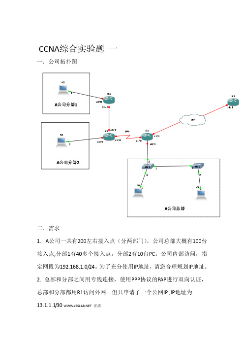
CCNA综合实验题一一.公司拓扑图二.需求1.A公司一共有200左右接入点(分两部门),公司总部大概有100台接入点,分部1有40多个接入点,分部2有10台PC。
公司内部访问,指定网段为192.168.1.0/24。
为了充分使用IP地址,请您合理规划IP地址。
2. 总部和分部之间用专线连接,使用PPP协议的PAP进行双向认证,总部和分部都用R1访问外网。
但只申请了一个公网IP ,IP地址为13.1.1.1/30 汪涛3. 总部内部有两个部门,分别属于两个VLAN(VLAN10,VLAN20)。
SW1为VTP 服务器,SW2为VTP 客户,要求内部VLAN间能相互通信。
4.分部1和分部2之间(R4和R2之间)运行RIP协议,总部和分部之间运行OSPF,要求全网能互通。
5. 总部访问公网使用帧中继技术,静态指定邻居。
6. 允许分部1访问总部,但分部2只能访问总部的HTTP服务器(IP地址:192.168.1.1《自己划分》),注意:HTTP服务器放在VLAN 10里。
分部1和分部2之间不能互访。
7.不影响其他流量的情况下,开启R2,R4的TELNET服务,只允许总部访问。
分部1和分部2不能互访,也不能访问总部。
CCNA综合实验题二该企业的具体环境如下:1、企业具有2个办公地点,且相距较远,公司总共大约有200台主机。
2、A办公地点具有的部门较多,例如业务部、财务部、综合部等,为主要的办公场所,因此这部分的交换网络对可用性和可靠性要求较高3、B办公地点只有较少办公人员,但是Internet的接入点在这里4、公司只申请到了一个公网IP地址,供企业内网接入使用5、公司内部使用私网地址【网络拓补】【需求分析】需求1:采取一定方式分隔广播域。
分析1:在交换机上划分VLAN可以实现对广播域的分隔。
划分业务部VLAN10、财务部VLAN20、综合部VLAN30,并分配接口。
需求二:核心交换机采用高性能的三层交换机,且采用双核心互为备份的形势,接入层交换机分别通过2条上行链路连接到2台核心交换机,由三层交换机实现VLAN之间的路由。

实验1-1:路由器初始配置【实验目的】:在本次实验中,你被要求从TFTP服务器(10.254.0.254/24)下载边界路由器PxR1和PxR2的基本配置。
在完成本次实验之后,你需要完成下列任务:从PxR1和PxR2路由器去连接TFTP服务器。
从TFTP服务器下载配置文件去配置你的路由器。
【实验拓扑】:上图显示了一个完成的本次实验拓扑图。
在这个实验中,你将需要通过帧中继连接到路由器PxR1和PxR2到路由器BBR1,并完成从TFTP服务器上下载配置文件。
注意:图中x为所在机架编号,y为路由器编号。
【实验帮助】:如果出现任何问题,可以向在值的辅导老师提出并请求提供帮助。
【命令列表】:使用TELNET或者其他终端程序建立与路由器建立联接。
记住在本实验中x是你的机架编号,y是你的路由器编号。
实验过程:第一步:连接路由器(PxR1和PxR2)。
你的路由器现在应该没有任何配置。
如果有,请使用erase start命令删除配置,并使用reload命令重启路由器。
注意:你应该使用一些最少的配置,以确保路由器能够到达TFTP服务器。
第二步:配置S0口为FRAME-RELAY封装格式。
第三步:分配IP地址给S0口。
你的IP地址应该为172.31.x.y/24, x代表你的机架编号,y代表你的路由器编号。
第四步:关闭帧中继网络的反向ARP。
手动的映射一个DLCI号到路由器BBR1(172.31.x.3)。
这个DLCI 号应该是由1xy来组成,其中x代表你的机架编号,y代表你的路由器编号。
举例来说P2R1将使用DLCI 121。
注意:为了使用帧中继映射支持类似路由协议通信的广播和组播,必须使用“broadcast”关键字第五步:激活S0接口,并退出配置模式。
第六步:使用ping命令验证PxR1和PxR2路由器与BBR路由器之间是否连通。
第七步:我们实验的目的是从TFTP服务器(10.254.0.254)下载文件,但是检查一下PxR1和PxR2的路由器显示出这里并没有一条路由到达TFTP服务器。

实验11 路由器的各种配置模式配置路由器名称用户模式特权模式配置模式配置主机的名字2配置登录空闲超时和输出同步进入console00分0秒表示永远不超时:防止长时间不操作,自动退出控控台线路登录。
3 配置输出同步,防止系统提示信息打断自己的输入。
logging synchronous4 为路由器设置提示标语:Banner motd ##5 为不同的接口配置接口描述Description7 为控制台这是密码Console 0password cisco注意一定要敲login 否则不生效6 为路由器设置特权模式设置密码明文密码密文密码enable password ciscoenable secret ciscolab8为虚拟终端线路配置密码Line vty 0 49配置加密密码将所有的明文密码加密10关闭域名查询解释: 默认情况下,路由器的DNS 查询是启用的,即当你错误的输入一条Cisco IOS 软件无法识别的命令的时候,路由器会把这个命令当成主机名,然后向DNS 服务器进行查询.一般实验性的环境中,如果我们没有DNS 服务器,因为输入错误的命令而造成无用的查询,是非常耗时的。
11.为路由器设置时间和时区实验2 配置静态路由配置静态路由的步骤:网络的静态路由选择的过程共有3歩:1.为网络中的所有数据链路确定子网或网络的地址2.为每台路由器标示所有非直连的数据链路3.为每台路由器写出关于每个非直连地址的路由语句配置静态路由静态路由不同的写下一跳的方法。
以太网不能写出口配置默认路由实验3 管理路由器的方式telnet实验4Rip的配置基本的RIP 配置验证RIP 的水平分隔和毒性逆转基本的RIPv2 配置Debug ip RIP有类路由协议:RIPv1 发送路由更新的时候,不能携带子网掩码。
发送路由更新:当网络地址和自己的接口的网络不在同一主网的时候,就汇总成主网地址;当和自己的接口的网络在同一个主网的时候,要和自己接口的掩码一致才发送。
LAB1.Cisco路由器基础配置路由器常用模式概述Router> 用户模式,通常用来查看统计信息,但不能修改路由器的设置。
Router# 特权模式,可以查看并修改路由器的配置,通常在这里运行show命令。
Router(config)# 全局模式,在这里修改当前运行配置中的内容。
Router(config-if)# 接口模式,用来配置路由器的物理接口和环回接口。
Router(config-subif)# 子接口模式,用来配置在路由器中创建的逻辑接口。
Router(config-line)# 控制台接口模式,通常用来配置用户模式口令,如Telnet的登陆密码等。
Router(config-router)# 路由协议接口模式,在这里配置路由协议,如RIP、EIGRP、OSPF等。
路由器配置加速Router>enableRouter#configure terminalRouter(config)#no ip domain lookup 关闭动态的域名解析,这样在敲错命令的时候会很快恢复,在某些型号路由器中命令格式为“no ip domain-lookup“Router(config)#line console 0Router(config-line)#exec-timeout 0 0 关闭控制台的空闲会话超时,保证不会被路由器自动踢除 Router(config-line)#logging synchronous 关闭日志同步,阻止控制台自动弹出的提示信息***以上几项功能将影响我们配置路由器的速度,推荐在每台设备上关闭***路由器的基本配置Router>enableRouter#conf tRouter(config)#hostname R1 配置路由器的主机名R1(config)#banner motd# 配置日期信息标志区(MOTD),登录到路由器时显示Enter TEXT message. End with the character '#'. 使用“#”为分隔符Hello Man !#R1(config)#banner exec #Going Down# 配置执行标志区,如Telnet路由器时显示的欢迎信息R1(config)#exitR1#clock set 15:14:30 24 july 2008 配置时钟路由器各种口令设置R1(config)#enable password cisco 特权明文密码,不安全的方式R1(config)#enable secret sovand 特权密文密码,权限高于明文,内容必须不同于明文R1(config)#line con 0 控制口密码,连接Console口登录配置时使用R1(config-line)#password sovandR1(config-line)#loginR1(config-line)#line vty 0 4 VTY线路登录密码,0-4代表5条线路,可支持5个IP同时登录R1(config-line)#password sovandR1(config-line)#login由于VTY及Console线路密码为明文,所以需要对明文进行加密,使用下列命令:R1(config)#service password-encryption查看加密后的口令:R1(config)#sh run取消口令设置R1(config)#no enable passwordR1(config)#no enable secretR1(config)#line cons 0R1(config-line)#no passwordR1(config-line)#no loginR1(config-line)#line vty 0 4R1(config-line)#no passwordR1(config-line)#no login路由器配置管理R1#show running-config 查看路由器当前配置R1#show startup-config 查看路由器启动配置文件R1#copy running-config startup-config 保存当前配置 Destination filename [startup-config]?Building configuration...[OK]R1#erase startup-config 删除启动配置文件Erasing the nvram filesystem will remove all files! Continue? [confirm] [OK]Erase of nvram: completeR1#R1#reload 重启路由器配置接口IP登录R1R1#conf tEnter configuration commands, one per line. End with CNTL/Z.R1(config)#int s0R1(config-if)#ip add 172.16.1.1 255.255.255.0R1(config-if)#no shut登录R2R2(config)#int s0R2(config-if)#ip add 172.16.1.2 255.255.255.0R2(config-if)#clock rate 64000 串行接口需要配置时钟同步R2(config-if)#no shut 开启接口R2(config-if)#end***查看接口及地址状态******测试直连网段连通性***LAB2. Route&RIPRequirements:1、某网络整体结构如果所示,在Router1上有3个回环口,IP地址如图,Router3连接两台主机使用路由器模拟,整个网络存在不连续子网问题。
现要求通过使用路由协议实现全网互联。
R1(config)#int loopback 1R1(config-if)#ip add 172.16.1.1 255.255.255.0R1(config-if)#int loo 2R1(config-if)#ip add 172.16.2.1 255.255.255.0R1(config-if)#int loo 3R1(config-if)#ip add 172.16.3.1 255.255.255.0R1(config)#int f0/0R1(config-if)#ip add 172.17.1.1 255.255.255.0R1(config-if)#no shR2(config)#int f0/0R2(config-if)#ip address 172.17.1.2 255.255.255.0R2(config-if)#no shR2(config-if)#int f1/0R2(config-if)#ip address 172.16.4.1 255.255.255.0R2(config-if)#no shR3(config)#int f0/0R3(config-if)#ip add 172.16.4.2 255.255.255.0R3(config-if)#no shR3(config)#int f1/0R3(config-if)#ip add 172.16.5.1 255.255.255.0R3(config-if)#no shR3(config-if)#int f2/0R3(config-if)#ip add 172.16.6.1 255.255.255.240R3(config-if)#no shPC1(config)#no ip routingPC1(config)#int f0/0PC1(config-if)#ip add 172.16.6.2 255.255.255.240PC1(config-if)#no shPC2(config)#no ip routingPC2(config)#int f0/0PC2(config-if)#ip add 172.16.6.2 255.255.255.240PC2(config-if)#no sh2、在各路由器上配置静态路由,要求使用尽可能少的路由条目实现全网互联。
r1(config)#ip route 172.16.4.0 255.255.252.0 172.17.1.2ip route 目标网段 目标网段的子网掩码 下一跳路由器ip地址R2(config)#ip route 172.16.0.0 255.255.252.0 172.17.1.1R2(config)#ip route 172.16.4.0 255.255.252.0 172.16.4.2r3(config)# ip route 172.16.0.0 255.255.252.0 172.16.4.1r3(config)#ip route 172.17.1.0 255.255.255.0 172.16.4.13、删除所有的静态路由,采用动态路由协议RIP,要求查看在默认版本情况下各路由器的路由表,分析路由学习的具体情况,通过debug分析有类路由协议以及路由的汇总情况。
R1(config)#no ip route 172.16.4.0 255.255.252.0 172.17.1.2R1(config)#router ripR1(config-router)#net 172.17.0.0R1(config-router)#net 172.16.0.0R2(config)#no ip route 172.16.0.0 255.255.252.0 172.17.1.1R2(config)#no ip route 172.16.4.0 255.255.252.0 172.16.4.2R2(config)#router ripR2(config-router)#net 172.16.0.0R2(config-router)#net 172.17.0.0R3(config)#no ip route 172.16.0.0 255.255.252.0 172.16.4.1R3(config)#no ip route 172.17.1.0 255.255.255.0 172.16.4.1R3(config)#router ripR3(config-router)#net 172.16.0.0R3向所有活动端口发送更新请求,送到同样运行在rip v1协议下的R2的更新应答。
网络边界发生汇总,R3收到来自F0/0的主类汇总通告,通告B类主类地址172.17.0.0/24.R3向邻居广播自己完整的rip v1路由,默认进行了水平分割不通告4.0网段,通告包括子网汇总路由172.16.4.0/25 跳数为1,主类汇总路由172.17.0.0/24 跳数为2。