SMC流量开关使用说明书
- 格式:pdf
- 大小:670.38 KB
- 文档页数:18


Instruction ManualDigital Flow Switch – Modular type PF3A701H / PF3A702HThe intended use of the digital flow switch is to monitor and display flow information while connected to the IO-Link communication protocol.These safety instructions are intended to prevent hazardous situations and/or equipment damage. These instructions indicate the level of potential hazard with the labels of “Caution,” “Warning” or “Danger.”They are all important notes for safety and must be followed in addition to International Standards (ISO/IEC) *1), and other safety regulations. *1)ISO 4414: Pneumatic fluid power - General rules relating to systems. ISO 4413: Hydraulic fluid power - General rules relating to systems.IEC 60204-1: Safety of machinery - Electrical equipment of machines. (Part 1: General requirements)ISO 10218-1: Manipulating industrial robots -Safety. etc.• Refer to product catalogue, Operation Manual and Handling Precautions for SMC Products for additional information. • Keep this manual in a safe place for future reference.CautionCaution indicates a hazard with a low level of risk which, ifnot avoided, could result in minor or moderate injury.WarningWarning indicates a hazard with a medium level of riskwhich, if not avoided, could result in death or serious injury.DangerDanger indicates a hazard with a high level of risk which, ifnot avoided, will result in death or serious injury.Warning• Always ensure compliance with relevant safety laws and standards.• All work must be carried out in a safe manner by a qualified person in compliance with applicable national regulations.• This product is class A equipment intended for use in an industrial environment. There may be potential difficulties in ensuring electromagnetic compatibility in other environments due to conducted or radiated disturbances.• Refer to the operation manual on the SMC website (URL: https:// ) for more safety instructions.2 Specifications2.1 IO-Link specifications • The IODD configuration file can be downloaded from the SMC website (URL: https:// ).Warning• Special products (-X) might have specifications different from those shown in this section. Contact SMC for specific drawings.Element DescriptionDisplay See belowConnector M12 4-pin connector for electrical connections. Lead wire with M12 connector Lead wire for power supply and outputs. Piping port For piping connections. BodyThe body of the product.3.1 Display• IO-Link specificationORIGINAL INSTRUCTIONSModelsPF3A701H PF3A702H Applicable fluid Air, N 2 Operating fluid temperature0 to 50 o C F l o w Detection method Heating sensor (branch flow) Rated flow range 10 to 1000 L/min 20 to 2000 L/min Set point range Instantaneousflow 10 to 1050 L/min 20 to 2100 L/min Accumulated flow 0 to 999,999,999,990 L Min. resolution Instantaneousflow1 L/min2 L/min Accumulated flow 10 L Accumulated volume per pulse (pulse width = 50 ms) Select from 10 L/pulse and 100 L/pulse Accumulated value hold 2 minutes or 5 minutes P r e s s u r e Rated pressure range 0 to 1.0 MPa Proof pressure 1.5 MPa Pressure loss Refer to the pressure loss graph Pressure Characteristics ±5.0 %F.S. (0 to 1.0 MPa, 0.5 MPa standard) E l e c t r i c a l Power supply voltage 24 VDC ±10% as switch output device21.6 to 30 VDC as IO-Link device Current consumption 150 mA or less Protection Polarity protection A c c u r a c yDisplay accuracy ±3.0 %F.S. Analogue outputaccuracy ±3.0 %F.S.Repeatability ±1.0 %F.S.Temperaturecharacteristics ±5.0 %F.S. (Ambient temp. 0 to 50 o C,25 o C standard)Impact when modular devices are connected ±5.0 %S w i t c h o u t p u tOutput type NPN or PNP open collector output Output mode Select one of output (hysteresis orwindow comparator mode), output for accumulated flow, accumulated pulse output.Switch operation Normal or reversed outputMaximum load current 80 mAMaximum applied voltage (NPN output) 28 VDC as switch output device 30 VDC as IO-Link device Internal voltage drop (Residual voltage) NPN: 1.5 V or less (load current 80 mA) PNP: 2.0 V or less (load current 80 mA)Delay time 3.3 ms or lessvariable at 0 to 60 s / 0.01 step Response time Select from 1 s, 2 s, 5 s.Hysteresis VariableProtection Over current protection A n a l o g u e O u t p u tOutput typeVoltage output: 1 to 5 V (0 to 10 V can be selected), Current output: 4 to 20 mA ImpedanceVoltage output Output impedance approx. 1 kΩ Current outputMax. load impedance 600 Ω Min. load impedance 50 Ω Response timeLinked to response time of switch output(output with digital filter setting)Models PF3A701HPF3A702HE x t . i n p u t Input type Input with no voltage: 0.4 V or less Input mode Select from Reset Accumulated Value, Reset Peak and Reset Bottom valuesTime for input 30 ms or moreD i s p l a y Reference condition Normal or Standard condition Display Display method: LCDNumber of displays: 2 (main display and sub display)Colour (main display): Red and green Display colour (sub display): OrangeDisplay - main display: 5 digits, 7 segment Display - sub display: 6 digits, 7 segment Operation LED OUT LED: Red is ON when output is ONE n v i r o n m e n t a lProtection IP65Withstand voltage 1000 V AC for 1 minute betweenterminals and housing Insulation resistance 50 MΩ between terminals and housing(with 500 VDC megger)Operating temperature range Operation: 0 to 50 o C, Storage: -10 to 60 o C (no condensation or freezing) Operating humidity range Operation, Storage: 35 to 85%RH(no condensation) Piping specification Modular (body size 30)Modular (body size 40)Material in contact with fluid SUS304, Aluminium alloy, PPS, HNBR (Sensor: Pt, Au, Ni, Fe, lead glass (notRoHS compliant), Al 2O 3)Lead wire with connector 3 mWeightBody 350 g400 gLead wire90 gElement DescriptionMain display Displays the instantaneous flow value and error codes. (2 colour display)Operation LED Indicates the output status of OUT.When the output is ON: Orange LED is ON. When the accumulated pulse output mode is selected, the output display will turn off.Sub display Displays the accumulated flow, set value, and peak/ bottom value when in measurement mode.▲ button (UP) Selects the mode and the display shown on theSub display or increases the switch point.S button (SET) Press this button to change the mode and to set a value.▼ button (DOWN) Selects the mode and the display shown on the Sub display or decreases the switch point.Units display (Instantaneous flow) Indicates the flow measurement units currently selected.Units display (Accumulated flow) Indicates the flow measurement units currently selected.IO-Link status indicator light LED is ON when OUT1 is used in IO-Link mode. (LED is OFF in SIO mode)4.1 InstallationWarning•Do not install the product unless the safety instructions have been read and understood.•Use the product within the specified operating pressure and temperature range.4.2 EnvironmentWarning•Do not use in an environment where corrosive gases, chemicals, salt water or steam are present.•Do not use in an explosive atmosphere.•Do not expose to direct sunlight. Use a suitable protective cover. •Do not install in a location subject to vibration or impact in excess of the product’s specifications.•Do not mount in a location exposed to radiant heat that would result in temperatures in excess of the product’s specifications.4.3 Mounting•Never mount the product in a location where it will be used as a mechanical support.•Mount the product so that the fluid flows in the direction indicated by the arrow on the side of the body.•Avoid mounting the product with the display facing upward.•Do not mount the product upside down.•The monitor with integrated display can be rotated. Rotating the display with excessive force will damage the end stop. 4.4 PipingCaution•Before connecting piping make sure to clean up chips, cutting oil, dustetc.•When installing piping or fittings, ensure sealant material does notenter inside the port.•Fit the raised part of the spacer to the recessed part (groove for theraised part) of the product.•Temporarily tighten the retainer A with two hexagon socket head capscrews.•Tighten the two hexagon socket head cap screws with a hexagonalwrench evenly.•Refer to the table below for the screws tightening torque.Applicable modelHex wrench socketnominal sizeTightening torquePF3A701H3 1.2 ±0.05 N•mPF3A702H•The following options are required for coupling with modular F, R, andL combinations. They are separately prepared by the user.Digital flowswitchAircombinationSpacerSpacer withbracketPipe adapterPF3A701H AC30#-D Y300-D Y300T-D E300-#03-DPF3A702H AC40#-D Y400-D Y400T-D E400-#04-D•Refer to the SMC website (URL: https://) for moredetails of options.Caution•Do not apply torsion or bending moment other than the weight of theproduct itself. External piping needs to be supported separately as itmay cause damage. If a moment applied to the equipment isunavoidable during operation, the moment should be lower than themaximum moment shown below. Non-flexible piping like steel tube issusceptible to excessive moment load or vibration. Insert flexible tubesto prevent this.Models PF3A701H PF3A702HMaximum moment (M): N•m 16 19.5Max. moment (M) = Length (L) x Load (F)4.5 WiringCaution•Do not perform wiring while the power supply is ON.•Confirm proper insulation of wiring.•Do not route wires and cables together with power or high voltagecables.The product can malfunction due to interference of noise and surgevoltage from power and high voltage cables. Route the wires of theproduct separately from power or high voltage cables.•If a commercially available switching power supply is used, be sure toground the frame ground (FG) terminal. If the product is connected tothe commercially available switching power supply, switching noise willbe superimposed and the product specifications will not be satisfied.In that case, insert a noise filter such as a line noise filter/ ferritebetween the switching power supplies or change the switching powersupply to the series power supply.Pin numbers ofconnectorWhen used as IO-Link deviceNo. NameWirecolourFunction1 DC(+) Brown 21.6 to 30 VDC2 N.C/Other WhiteNot connected /Analogue output orExternal input3 DC(-) Blue 0 V4 C/Q BlackIO-Link data /Switch output (SIO)5 Function Setting5.1 Function selection modeIn measurement mode, press the SET button for 3 seconds or longer todisplay [F 0].Press the UP or DOWN button to select the function to be changed.Press and hold the SET button for 2 seconds or longer in functionselection mode to return to measurement mode.Refer to the SMC website (URL: https://) for moresetting details.5.1 Default settings∗: Items in brackets are IO-Link specifications.• Flow switch setting and functions • IO-Link functions • Zero cut off functionRefer to the operation manual on the SMC website (URL: https:// ) for setting these functions.Refer to the SMC website (URL: https:// ) for more How to Order details.Refer to the SMC website (URL: https:// ) for details of Outline dimensions..9.1 General MaintenanceCaution• Not following proper maintenance procedures could cause the product to malfunction and lead to equipment damage.• If handled improperly, compressed air can be dangerous.• Maintenance of pneumatic systems should be performed only by qualified personnel.• Before performing maintenance, turn off the power supply and be sure to cut off the supply pressure. Confirm that the air is released to atmosphere.• After installation and maintenance, apply operating pressure and power to the equipment and perform appropriate functional and leakage tests to make sure the equipment is installed correctly.• If any electrical connections are disturbed during maintenance, ensure they are reconnected correctly and safety checks are carried out as required to ensure continued compliance with applicable national regulations.• Do not make any modification to the product.• Do not disassemble the product, unless required by installation or maintenance instructions. • Remove condensate periodically.If condensate enters the secondary side, it can cause operating failure of pneumatic equipment.• Do not use solvents such as benzene, thinner etc. to clean the product. This may damage the surface of the body or erase the markings on the body.Use a soft cloth to remove stains.For heavy stains, use a damp cloth that has been soaked with diluted neutral detergent and fully squeezed, then wipe up the stains again with a dry cloth.• How to reset the product after a power cut or when the power has been unexpectedly removedThe settings of the product are retained from before the power cut or de-energizing.The output condition also recovers to that before the power cut or de-energizing, but may change depending on the operating environment. Therefore, check the safety of the whole system before operating the product.10.1 Limited warranty and Disclaimer/Compliance Requirements Refer to Handling Precautions for SMC Products.This product should not be disposed of as municipal waste. Check your local regulations and guidelines to dispose of this product correctly, in order to reduce the impact on human health and the environment.Refer to or www.smc.eu for your local distributor / importer.URL: https:// (Global) https://www.smc.eu (Europe) SMC Corporation, 4-14-1, Sotokanda, Chiyoda-ku, Tokyo 101-0021, Japan Specifications are subject to change without prior notice from the manufacturer. © 2021 SMC Corporation All Rights Reserved. Template DKP50047-F-085MFunction (Main display) Default Settings (Right sub display) (Main display) (Left sub display) [F 0][rEF ] Select display units [ Std] Standard condition [Uni ] ([Unit]) Units selectionfunction [ L] L/min ([NorP]) Select NPN/PNP ([ PnP]) PNP output [F 1] [oUt ] ([oUt1]) Select output mode[ HYS] Hysteresis mode[ ot ] ([1ot ]) Select switch mode [ P] ([ 1_P]) Normal output[ P] ([P_1 ]) Select input switchoperation[ 500] 500 L/min (PF3A701H) [1000] 1000 L/min (PF3A702H) [ H] ([H_1 ]) Setting of Hysteresis [ 50] 50 L/min (PF3A701H) [ 100] 100 L/min (PF3A702H)([dt1 ]) Delay time setting ([0.00]) 0.00 s [CoL ] Select display colour [ SoG] ([1SoG]) Green when ON Red when OFF (OUT1) ([F 2])[oUt2] Select output mode [ HYS] Hysteresis mode [2ot ] Select switch mode [ 2_P] Normal output [P_2 ] Select input switchoperation [ 500] 500 L/min (PF3A701H) [1000] 1000 L/min (PF3A702H) [H_2 ] Setting of Hysteresis[ 50] 50 L/min (PF3A701H) [ 100] 100 L/min (PF3A702H) [dt2 ] Delay time setting [0.00] 0.00 s [CoL ] Select display colour [1SoG] Green when ONRed when OFF (OUT1)[F 3] [FiL ] Select digital filter[ 1.0] 1 second [F 5] [FnC ] ([FUnC]) Select FUNC (switching analogueoutput/external input)[ oUt] ([AoUt]) Analogueoutput [F10] [SUb ] Select sub display(Line name setting)[ dEF] Default setting [F13] [rEv ] Select Reverse display [ oFF] Reverse display OFF [F14] [CUt ] Select Zero cut-off setting [ 1.0] 1%F.S. cut[F30] [SAv ] ([SAvE]) Accumulated value hold [ oFF] Not stored[F80] [dSP ] ([diSP]) Display OFFmode[ on] Display ON [F81] [Pin ]Security code [ oFF] Not used [F90] [ALL ] Setting of all functions [ oFF] Not used [F96] [Sin ] ([S_in]) Check of input signal [ - - - ] No input signal[F98] [tES ] ([tESt]) Setting ofoutput check[ n] Normal output [F99] [ini ] Reset to the default settings [ oFF] Not used。

3.1流量表設定操作
◆F1操作(工作模式設定)
長按SET鍵,進入F1模式,按SET鍵
選擇後
●就進入n 1 和H 1介面
1.n1設置,一般n1值設置成實際值的三分之一
如:實際值是0.24, n1值就設為0.08
2.H 1設置,一般H 1值設置成實際值的八分之一
如:實際值是0.24, H 1值就設為0.03
●顏色設定:(我們都設為綠、紅切換)
進入F1模式,按SET鍵
選擇
選擇後
再選擇
選完之後,按到出現F1的介面後長按SET鍵退出
◆F3操作(反應時間設定)
長按SET鍵,進入F3模式
出現
按上下鍵設定數字
我们流量計設定.002就可以◆F5操作(省電模式設定)
當表出現
這個介面時
長按SET鍵,選擇F5進入模式
設置成
即可恢復正常使用
◆F95操作(流量大小設定模式)這種模式要視流量計而定
通常我們使用的流量計是PFMV510和PFMV530
1.PFMV510是單向,有方向選擇性
PFMV510廠家設置的流量大小範圍是0~1.0(L/min)通常我們設置成1.0(L/min)
2.PFMV530是雙向,沒有方向選擇性
PFMV510廠家設置的流量大小範圍是0~3.0(L/min)通常我們設置成3.0(L/min)。

S M C电气比例阀中文手
册
Company Document number:WTUT-WT88Y-W8BBGB-BWYTT-19998
SMC电气比例阀中文手册
阀对流量的控制可以分为两种:
一种是开关控制:要么全开、要么全关,流量要么最大、要么最小,没有中间状态,如普通的电磁直通阀、电磁换向阀、电液换向阀。
另一种是连续控制:阀口可以根据需要打开任意一个开度,由此控制通过流量的大小,这类阀有手动控制的,如节流阀,也有电控的,如比例阀、伺服阀。
所以使用比例阀或伺服阀的目的就是:以电控方式实现对流量的节流控制(当然经过结构上的改动也可实现压力控制等),既然是节流控制,就必然有能量损失,伺服阀和其它阀不同的是,它的能量损失更大一些,因为它需要一定的流量来维持前置级控制油路的工作。

产品名称:SMC电气比例阀说明书
阀对流量的控制可以分为两种:
一种是开关控制:要么全开、要么全关,流量要么最大、要么最小,没有中间状态,如普通的电磁直通阀、电磁换向阀、电液换向阀。
另一种是连续控制:阀口可以根据需要打开任意一个开度,由此控制通过流量的大小,这类阀有手动控制的,如节流阀,也有电控的,如比例阀、伺服阀。
所以使用比例阀或伺服阀的目的就是:以电控方式实现对流量的节流控制(当然经过结构上的改动也可实现压力控制等),既然是节流控制,就必然有能量损失,伺服阀和其它阀不同的是,它的能量损失更大一些,因为它需要一定的流量来维持前置级控制油路的工作。

Flow MonitorOperation ManualPF2A3/PF2W3/PF2D3Installation•Never mount the product in a location that will be used as a foothold.Thank you for purchasing an SMC PF2A3/PF2W3/PF2D3Series Flow Monitor.Please read this manual carefully before operating the product and make sure you understand its capabilities and limitations.Please keep this manual handy for future reference.To obtain more detailed information about operating this product, please refer to the SMC website (URL ) or contact SMC directly.These safety instructions are intended to prevent hazardous situations and/or equipment damage.These instructions indicate the level of potential hazard with the labels of"Caution", "Warning" or "Danger". They are all important notes for safety and must be followed in addition to International standards (ISO/IEC) and other safety regulations.OperatorSafety InstructionsMaintenanceHow to reset the product after a power cut or forcible de-energizing The setting of the product will be retained as it was before a power cut or de-energizing.The output condition is also basically recovered to that before a power cut or de-energizing, but may change depending on the operating environment.Therefore, check the safety of the whole installation before operating the product.Mounting and InstallationInstallingRemoving the panel mount adapter•Remove the panel mount adapter from the product if it has been delivered assembled.•Remove the mounting bracket using a flat blade screwdriver.•Lever the hook to the outside to remove the adapter (See below).•If the panel mount adapter is pulled with the hook engaged, the product or the panel mount adapter will be damaged.FrontBackList of outputsFind the diagram of the output required in the table below. Perform settings following the Set value column on the right. Characters in ( ) are for OUT2.Key-lock functionThis function is used to prevent errors occurring due to unintentional changes of the set values.Default settingsThe default settings are as follows.If this condition is acceptable, then keep these settings.Default settingsThe default settings are as follows.If this condition is acceptable, then keep these settings.∗: When Non-Reverse output is selected as the switching operation, n becomes P.button, to display [F_].This [F_∗: When OUT1 or OUT2 is assigned to be instantaneous output mode during initialize mode, [F_1] and [F_2] are displayed.When OUT1 or OUT2 is assigned to be accumulated output mode, [F_3] is displayed.Items below can be set.•Connected sensor •Display mode •Unit selection function ∗•Output mode (OUT1)•Output mode (OUT2) •Switch operation (OUT1)•Switch operation (OUT2)•Reference condition TroubleshootingMounting with the panel mount adapter •Install the product as shown below.•Insert panel mount adapter B into section A of panel mount adapter A.Push panel mount adapter B from behind until the display is fixed onto the panel.The pin of panel mount adapter B engages the notched part of panel adapter section A to fix the display.Wiring•Connections should only be made with the power supply turned off.•Use separate routes for the product wiring and any power or high voltage wiring. Otherwise, malfunction may result due to noise.•Ensure that the FG terminal is connected to ground when using a commercially available switch-mode power supply. When a switch-mode power supply is connected to the product, switching noise will be superimposed and theproduct specification can no longer be met. This can be prevented by inserting a noise filter, such as a line noise filter and ferrite core, between the switch-mode power supply and the product, or by using a series power supply instead of a switch-mode power supply.Connecting the wiring•Use suitable crimp terminals for connection to the terminal block.•Attention should be paid to the terminals to avoid short circuits.Terminal block numberPower is suppliedOutline of settingMeasurement modeThe mode in which the flow is detected and displayed,and the switch function is operating.This is the basic operating mode;and other modes should be selected for settingchanges and other function settings.Function selection modeSpecification / Outline with DimensionsRefer to the product catalogue or SMC website (URL ) for more information about product specifications and outline dimensions in detail.Note: Specifications are subject to change without prior notice and any obligation on the part of the manufacturer.© 2011 SMC Corporation All Rights ReservedAkihabara UDX 15F , 4-14-1, Sotokanda, Chiyoda-ku, Tokyo 101-0021, JAP AN Phone: +81 3-5207-8249 Fax: +81 3-5298-5362URL Refer to the SMC website (URL ) for more information about troubleshooting.∗1: In window comparator mode, the hysteresis is fixed at 3 digits. When setting, allow 7 digits or more betweenSet point 1 and Set point 2 (Set point 3 and Set point 4).∗2: When Set point 1 = Set point 2 (Set point 3 = Set point 4), chattering may occur.Refer to the product catalogue or SMC website (URL )for more detailed information about panel cut-out dimensions.。

SMC数字式流量计只卖正品PF2MC7102—04—B—M正品SMC数字式流量开关新款新产品只售原装:smc空气用数字式流量开关,smc流量开关pf2a系列说明书·特地用来监测液体、气体的流速·采用磁性动作,没有机械连接,操作简单可靠。
电子式流量开关/传感器规格:PF2MC7系列3色显示3画面数字式流量开关●适合流体:干燥空气、N2●3色3画面显示●1个产品即可测量广泛的流量范围流量范围比100:1、最小设定单位1L/min●无润滑脂●对应IOLink2色显示式数字式流量传感器PF2M7(L)追加流量范围:2~200L/min配管引出方向:追加后面方向追加流量调整阀(0.05~5L/min)干燥空气、N2、Ar、CO21台可测量广泛的流量,流量范围100:1、最小设定单位0.01L/min对应IOLink耐冷凝水·耐异物性提高小型·轻量无润滑脂2色显示式数字式流量开关PFM可用于空气、N2、Ar、CO2无润滑脂规格。
与流量调整阀一体化。
体积小、重量轻、省空间。
※PFM系列于2023年3月停止生产。
请选择PF2M710/725/750/711系列。
2色显示式数字式流量开关PFMB干燥空气、N2无润滑脂规格与流量调整阀一体化体积小、省空间※PFMB7201系列已于2023年9月停产。
请选择PF2M721系列。
3色显示式数字式流量传感器PF2MC7□(L)适合干燥空气、N23色3画面显示1个产品即可测量广泛的流量范围流量范围比100:1,最小设定单位1L/min无润滑脂对应IOLink3色显示式数字式流量开关/大流量型PF3A□H(L)适合流体:空气, N2流量范围:最大12,000L/min范围本领 100:11台流量开关可计测大范围的流量耐冷凝水、耐异物本领提高压力损失降低75%(20kPa→5kPa)贯穿构造对应IOLink可连接气动组件(模块型)有带4画面压力/温度传感器(模块型)的型号(积累)可同时计测流量/压力/温度正品SMC数字式流量计新款新产品只售原装;正品SMC数字式流量开关新款新产品只售原装SMC数字式流量计PFMC710204BM新款PF2MC710204BM。


Instruction ManualAuto switch (Solid state) - Heat ResistantSeries D-M9NJ# / D-M9PJ#The intended use of the auto switch is to detect and control the position of an actuator using magnetic detection.These safety instructions are intended to prevent hazardous situations and/or equipment damage. These instructions indicate the level of potential hazard with the labels of “Caution,” “Warning” or “Danger.”They are all important notes for safety and must be followed in addition to International Standards (ISO/IEC) *1), and other safety regulations. *1)ISO 4414: Pneumatic fluid power - General rules relating to systems. ISO 4413: Hydraulic fluid power - General rules relating to systems. IEC 60204-1: Safety of machinery - Electrical equipment of machines. (Part 1: General requirements)ISO 10218-1: Manipulating industrial robots -Safety. etc.• Refer to product catalogue, Operation Manual and Handling Precautions for SMC Products for additional information. • Keep this manual in a safe place for future reference.CautionCaution indicates a hazard with a low level of risk which, if not avoided, could result in minor or moderate injury.WarningWarning indicates a hazard with a medium level of riskwhich, if not avoided, could result in death or serious injury.DangerDanger indicates a hazard with a high level of risk which, ifnot avoided, will result in death or serious injury.Warning• Always ensure compliance with relevant safety laws and standards.• All work must be carried out in a safe manner by a qualified person in compliance with applicable national regulations.• This product is class A equipment intended for use in an industrial environment. There may be potential difficulties in ensuring electromagnetic compatibility in other environments due to conducted or radiated disturbances.• Refer to the operation manual on the SMC website (URL: https:// ) for all Safety Instructions.Warning• Special products (-X or -####) might have specifications different from those shown in the Specifications section. Contact SMC for specific drawings.2 SpecificationsModelD-M9NJ# D-M9PJ# Output type NPN typePNP typePower supply voltage 20 to 26 VDC Currentconsumption 25 mA or lessLoad voltage 28 VDC or less- Load current 40 mA or lessInternal voltage drop0.8 V or lessLeakage current 100 µA or less at 24 VDCIndicator lightOperating range: Red LED lights up. Optimum range: Green LED lights up.Lead wireHeat resistant lead wire φ3.4 mm (between sensor and amplifier) Oilproof heavy-duty vinyl cable(cable to amplifier unit)φ3.4 mm, 0.2 mm 2, 3-wire, 3000 mmImpact resistance Sensor unit: 1000 m/s 2, Amplifier unit: 300 m/s 2Insulation resistance50 MΩ min. under 500 VDC test voltage(between lead wire and case)Withstand voltage 1000 VAC, 1 min. (between lead wire and case)Ambient temperature Sensor unit: 0 to 150 o C, Amplifier unit: 0 to 60 o C Enclosure Sensor unit: IP67,Amplifier unit: IP65 (IEC60529)4 Installation4.1 InstallationWarning• Do not install the product unless the safety instructions have been read and understood. 4.2 Design and Selection 1) Confirm the specifications.Read the specifications carefully and use the product correctly. The product may be damaged or malfunction if it is used outside of the specification range.2) Take precautions when multiple actuators are used close together. When multiple auto switch actuators are used in close proximity, magnetic field interference may cause the switches to malfunction. Maintain a minimum actuator separation of 40 mm.3) Pay attention to the length of time that a switch is ON at an intermediate stroke position.When an auto switch is placed at an intermediate position of the stroke and a load is driven at the time the piston passes, the auto switch will operate, but if the speed is too great the operating time will be short and the load may not operate correctly. The maximum detectable piston speed is:V (mm/s) = Auto switch operating range (mm)X 1000Load operating time (ms)4) Keep wiring as short as possibleAlthough long wire length does not affect the switch function, it is recommended to keep it to 100 m or less.5) Do not use a load that generates surge voltage.Although a zener diode for surge protection is connected at the output side of a solid state auto switch, damage may still occur if the surge is applied repeatedly. When a load such as a relay or solenoid which generates surge is directly driven, use a type of switch with built in surge protection.6) Caution for use in an interlock circuitWhen an auto switch is used for an interlock signal requiring high reliability, devise a double interlock system by providing a mechanical protection function, or by using another switch (sensor) together with the auto switch.7) Perform periodic maintenance and confirm proper operation. Ensure sufficient clearance for maintenance activities.When designing an application, be sure to allow sufficient clearance for maintenance and inspections. 4.3 Mounting and Adjustment 1) Do not drop or bump the product.Do not drop, bump or apply excessive impact (1000 m/s 2 or more) while handling. Although the body of the switch may not appear damaged, the inside of the switch could be damaged and cause a malfunction.2) Do not carry an actuator by the auto switch lead wires.This may not only cause broken lead wires, but it may cause internal elements of the switch to be damaged by the stress. 3) Mount switches using the correct tightening torque.The tightening torque of the mounting screw must be 0.05 to 0.15 N•m (0.5 to 1.5 kgf•cm).If a switch is tightened beyond the tightening torque range, the mounting screw, mounting bracket or switch may be damaged.On the other hand, tightening below the tightening torque range may allow the switch to slip out of position.4) Mount a switch at the centre of the operating range.Adjust the auto switch mounting position so that the piston stops atthe centre of the operating range (the range in which the switch is ON). The mounting position shown in the catalogue indicates the optimum position at the end of stroke. If mounted at the end of the operating range (around the borderline of ON and OFF) operation may be unstable.5) The auto switch ON and OFF position operates with a hysteresis. If the hysteresis causes a problem, please consult with SMC.4.4 Auto switch mountingEach actuator has a specified mounting bracket type.Mounting depends on the actuator type and bore size. Please refer to the actuator catalogue.When an auto switch is mounted for the first time, ensure that the actuator is the type with a built-in magnet before assembly.5.1.1 Setting the Detection position Set the actuator at the stroke end.Set the Auto switch in the centre of the position where the auto switch green light is ON (optimum position).Based on dimensions A and B in the actuator catalogue, set the auto switch position. Tighten the mounting screw to the required torque.5.2 Amplifier mountingThe auto switch amplifier unit should be mounted on a DIN rail.Hold the hook on the bottom of the unit on to the DIN rail, and then push down on to the DIN rail.For removal, release the unit using a screwdriver.Mounting5.3 Wiring1) Avoid repeatedly bending or stressing lead wires.Broken lead wires can result from wiring layouts which repeatedly apply bending stress or stretching force to the lead wires. 2) Confirm proper insulation of wiring.Check that there is no faulty wiring insulation (contact with other circuits, ground fault, improper insulation between terminals, etc.) Damage may occur due to excess current flow into a switch. 3) Do not route wiring with power lines or high voltage lines.Avoid parallel wiring or wiring in the same conduit with these lines. Control circuits containing auto switches may malfunction due to noise. 4) Do not allow short circuit of loads.The auto switch does not have built-in short circuit protection. Note that if a load is short circuited, the switch will be instantly damaged because of excess current flow into the switch. 5) Avoid incorrect wiring.If wiring is incorrect the switch will be damaged.5.4 Wiring diagram 5.4.1 D-M9NJ# - NPN output5.4.2 D-M9PJ# - PNP outputORIGINAL INSTRUCTIONS5.5 EnvironmentWarning•Do not use in an environment where oil, corrosive gases, chemicals, salt water or steam are present.• Do not install in a location subject to vibration or impact in excess of the product specifications.• Do not mount in a location exposed to radiant heat that would result in temperatures in excess of the product specification.• Do not use in an area where a magnetic field is generated.Auto switches can malfunction or magnets inside actuators can become demagnetized.• Do not use in an environment where the auto switch will be continually exposed to water.• Do not use in an environment with temperature cycles.• Avoid accumulation of iron waste or close contact with magnetic substances. A large amount of accumulated iron waste such as machining chips or spatter may cause the auto switch to malfunction.6.1 General MaintenanceCaution• Not following proper maintenance procedures could cause the product to malfunction and lead to equipment damage.• If handled improperly, compressed air can be dangerous.• Maintenance of pneumatic systems should be performed only by qualified personnel.• Before performing maintenance, turn off the power supply and be sure to cut off the supply pressure. Confirm that the air is released to atmosphere.• After installation and maintenance, apply operating pressure and power to the equipment and perform appropriate functional and leakage tests to make sure the equipment is installed correctly. • If any electrical connections are disturbed during maintenance, ensure they are reconnected correctly and safety checks are carried out as required to ensure continued compliance with applicable national regulations.• Do not make any modification to the product.• Do not disassemble the product, unless required by installation or maintenance instructions.• Perform the following maintenance periodically in order to prevent possible danger due to unexpected auto switch malfunction.1) Securely tighten switch mounting screws. If screws become loose or the mounting position is dislocated, re-tighten them after readjusting the mounting position.2) Confirm that there is no damage to lead wires. To prevent faulty insulation, replace switches or repair lead wires, etc., if damage is discovered.How to reset the product after power loss or forced de-energizing Regarding set up, contents of the program may be maintained by the customers application system. Be sure to confirm safety when returning operation of the actuator because it could have been stopped in an unstable condition.Refer to the catalogue or operation manual on the SMC website (URL: https:// ) for How to order information.Refer to the catalogue or operation manual on the SMC website (URL: https:// ) for outline dimensions.When detection failure occurs check the switch based on the flow chart.10.1 Limited warranty and Disclaimer/Compliance Requirements Refer to Handling Precautions for SMC Products.11 Product disposalThis product should not be disposed of as municipal waste. Check yourlocal regulations and guidelines to dispose of this product correctly, in order to reduce the impact on human health and the environment.12 ContactsRefer to or www.smc.eu for your local distributor / importer.URL: https:// (Global) https:// (Europe) SMC Corporation, 4-14-1, Sotokanda, Chiyoda-ku, Tokyo 101-0021, Japan Specifications are subject to change without prior notice from the manufacturer. © 2021 SMC Corporation All Rights Reserved. Template DKP50047-F-085MProblem occurs Stays OFF(sometimes ON) NormalProblem condition 3 wiresNormal AbnormalWiring (output check) 2 wires 2 wires / 3 wires Normal Abnormal Load spec. check (1) Normal Abnormal Replace auto switch Stays OFF Stays ON (sometimes OFF) Normal Abnormal Indication light Source voltage or load voltageNormal 3 wires 2 wires / 3 wires Stays OFF 2 wires Normal Abnormal Load spec. check (2) Indication light Stays ON (A) (B) (A) (C) (D) (E) (B) (B) (A) (A) (F) (D)。

TroubleshootingSpecificationThe IODD file can be downloaded from the SMC website (URL ).Refer to the product catalogue or SMC website (URL ) for more detailed information about product specifications.DimensionsRefer to the product catalogue or SMC website (URL ) for more detailed information about dimensions.than above are displayed, please contact SMC.Error indication functionThis function is to display error location and content when a problem or error has occurred.Snap shot functionThe current flow/temperature value can be stored to the switch output ON/OFF set point.When the set value and hysteresis are set, press the UP and DOWN buttons for 1 second or longer simultaneously. Then, the set value of the sub display (right) shows [- - -], and then values corresponding to the current flow/temperature are automatically displayed.Peak/bottom value indicationThe maximum (minimum) flow/temperature when the power is supplied is detected and updated.The value can be displayed on the sub display by pressing the UP or DOWN button in measurement mode.Key-lock functionTo set this function, refer to SMC website (URL ) for more detailed information or contact us.MaintenanceHow to reset the product after a power cut or when the power has been unexpectedly removedThe settings of the product are retained from before the power cut or de-energizing.The output condition also recovers to that before the power cut or de-energizing,but may change depending on the operating environment.Therefore, check the safety of the whole system before operating the product.Function selection modeSelect to display the function to be change [F mode to return to measurement mode.The function number is increased and decreased by the UP and DOWN buttons.Display the required function number and press the SET button.Default settingsThe default settings are provided as follows. If these settings are acceptable,retain for use. To change setting, refer to SMC website(URL ) for more detailed information or contact us.Display of sub screenIn measurement mode, the display of the sub screen can be temporarily changed by pressing the UP or DOWN buttons.After 30 seconds, it will automatically reset to the display selected in [F10].(Example shown is for 16 L/min type)∗: Arbitrary display∗: An arbitrary display can be added to the sub display by setting in [F10].If the sub display is switched during the arbitrary display, the display will return to the arbitrary display 30 seconds later.(The default setting does not include arbitrary display).Refer to the SMC website (URL ) for more detailed information about product troubleshooting.Note: Specifications are subject to change without prior notice and any obligation on the part of the manufacturer.© 2019 SMC Corporation All Rights Reserved Akihabara UDX 15F, 4-14-1, Sotokanda, Chiyoda-ku, Tokyo 101-0021, JAPAN Phone: +81 3-5207-8249 Fax: +81 3-5298-5362URL PF ※※-OMW0011Safety InstructionsFlow SettingInstallationBracket mounting (PF3W704/720/740)Mount the product (with bracket) usingthe mounting screws supplied (M4 x 4 pcs.).For models with flow adjustment valve attached, fix using 8 mounting screws.Bracket thickness is approx. 1.5 mm.Measurement modeThe mode in which the flow is detected and displayed, and the switch function is operating.This is the basic operating mode; other modes should be selected for set-point and other function setting changes.Approx. 3 seconds for this period)Mounting and InstallationInstallation•Use the product within the specified operating pressure and temperature range.•Proof pressure could vary according to the fluid temperature.Check the characteristics data for operating pressure and proof pressure.(4-pins)(Option)(Option)Direct mounting (PF3W704/720/740)Mount using the self tapping screws(nominal size: 3.0 x 4 pcs.) for installation.For models with flow adjustment valveattached, mount using 8 self tapping screws.The tightening torque must be 0.5 to 0.7 Nm.PipingWhen connecting piping to the product, a spanner should be used on the metal piping attachment only.Using a spanner on other parts may damage the product.In particular, do not let the spanner come into contact with the M8 connector.The connector can be easily damaged.If the tightening torque is exceeded, the product can be broken. If the correct tightening torque is not applied, the fittings may become loose.Avoid any sealing tape getting inside the piping.Ensure there is no leakage from loose piping.3/820.9 mm 1/223.9 mm 3/429.9 mm After hand tightening the piping, apply a spanner of the correct size to the spanner flats on the product, and tighten it for 2 to 3 rotations.Direct mounting (PF3W711)Mount using the self tapping screws(nominal size: 4.0 x 4 pcs.) for installation.The tightening torque must be 1.0 to 1.2 Nm.The self tapping screws should not be re-used.Refer to the outline dimension drawing for mounting hole size.Refer to the product catalogue or SMC website (URL )for more detailed information.WiringWiring of connectorConnections should only be made with the power supply turned off.Use separate routes for the Flow switch wiring and any power or high voltage wiring. Otherwise, malfunction may result due to noise.Ensure that the FG terminal is connected to ground when using a commercially available switch-mode power supply. When a switch-mode power supply isconnected to the product, switching noise will be superimposed and the product specification can no longer be met. This can be prevented by inserting a noise filter, such as a line noise filter and ferrite core, between the switch-mode power supply and the product, or by using a series power supply instead of a 141 mmHow to adjust the flow rate(when a flow adjustment valve is mounted)to the target value.(2) Be sure to confirm that there is no fluid leakagegenerated after adjustment.(When fluid leakage is generated, open and close the valve several times for re-adjustment, and confirm that there is no fluid leakage.)(3) Tighten the lock ring to fix the valve as necessary.The flow adjustment valve is not designed forapplications that require daily and repetitive adjustment.If the valve is adjusted frequently, fluid may leak due to wear of the internal seal.BodyDisplayBracket mounting (PF3W711)Mount the product (with bracket) usingthe mounting screws supplied (M5 x 4 pcs.).Bracket thickness is approx. 2 mm.2. Press the UP or DOWN button to change the set value.The UP button is to increase and the DOWN button is to decrease the set value.•Press the UP button once to increase by one digit, or press and hold to continuously increase.3. Press the SET button to finish the setting.•Press the DOWN button once todecrease by one digit, or press and hold to continuously decrease.Mounting•Never mount the product in a location where it will be used as a support.•Mount the product so that the fluid flows in the direction indicated by the arrow on the side of the body.•Check the flow characteristics data for pressure loss and the straight inlet pipe length effect on accuracy, to determine inlet piping requirements.•Do not sharply reduce the piping size.•The monitor with integrated display can be rotated. It can be set at 90o intervals clock and anticlockwise, and also at 45o and 225o clockwise. Rotating the display with excessive force will damage the end stop.∗: When using the lead wire with M8 connector included with the PF3W7 series.Refer to the product catalogue or SMC website (URL )for more detailed information.Before UseDigital Flow Switch(Integrated display type)PF3W7##-LThank you for purchasing an SMC PF3W7##-L Series Digital Flow Switch (Integrated display type).Please read this manual carefully before operating the product and make sure you understand its capabilities and limitations. Please keep this manual handy for future reference.Safety InstructionsThese safety instructions are intended to prevent hazardous situations and/or equipment damage.These instructions indicate the level of potential hazard with the labels of"Caution", "Warning" or "Danger". They are all important notes for safety and must be followed in addition to International standards (ISO/IEC) and other safety regulations.OperatorWidth across flats of attachment1. Press the SET button in measurement mode to display set values.(The item to be changed is displayed on the sub display)Tighten the connector by hand.The switch turns on within a set flow range (from P1L to P1H) during window comparator mode. Set P1L (switch lower limit) and P1H (switch upper limit) using the setting procedure above.When reversed output is selected, the main screen displays [n1L] and [n1H].To set accumulated output functions, refer to the product catalogue orSMC website (URL ) for more detailed information.For models with 2 outputs, [P_2] or [n_2] will be displayed. Set as above.For models with the temperature sensor attached, [ tn] will be displayed.When the fluid temperature falls below the set value, the output turns ON.∗: If a button operation is not performed for 30 seconds during the change of setting, the set value will start flashing.。

Digital Flow SwitchOperation ManualPFM7•Install the product (with bracket) using the M3 screws (4 pcs.).•Bracket thickness is approximately 1.2 mm.DIN rail mounting (using ZS-33-R )•Mount the DIN rail mounting parts using DIN rail mounting screws and joint screws supplied.•The required tightening torque of the DIN rail mounting screws and joint screws is 0.4±0.05 Nm.Safety InstructionsInstallationRefer to the product catalogue or SMC website (URL ) for more information about panel cut-out and mounting hole dimensions.Panel mounting•Insert Panel Mount Adapter B (supplied as an accessory) into Section A of Panel Mount Adapter A.Push Panel Mount Adapter B from behind until the display is fixed onto the panel.The pin of Panel Mount Adapter B engages the notched part of Panel Adapter section C to fix the display.Mounting and InstallationWiringWiring of connector•Connections should only be made with the power supply turned off.•Use separate routes for the product wiring and any power or high voltage wiring.Otherwise, malfunction may result due to noise.•Ensure that the FG terminal is connected to ground when using a commerciallyavailable switch-mode power supply. When a switch-mode power supply is connected to the product, switching noise will be superimposed and the product specification can no longer be met. This can be prevented by inserting a noise filter, such as a line noise filter and ferrite core, between the switch-mode power supply and the product, or byusing a series power supply instead of a switch-mode power supply.Thank you for purchasing an SMC PFM7 Series Digital Flow Switch.Please read this manual carefully before operating the product and make sure you understand its capabilities and limitations.Please keep this manual handy for future reference.To obtain more detailed information about operating this product,please refer to the SMC website (URL ) or contact SMC directly.These safety instructions are intended to prevent hazardous situations and/or equipment damage.These instructions indicate the level of potential hazard with the labels of"Caution", "Warning" or "Danger". They are all important notes for safety and must be followed in addition to International standards (ISO/IEC) and other safety regulations.NOTEThe direct current power supply used should be UL approved as follows.Circuit (class 2) of maximum 30 Vrms (42.4 V peak) or less, with UL 1310class 2 power supply unit or UL 1585 class 2 transformer.The product is a approved product only if it has a mark on the body.Bracket mounting•Mount the bracket using the mounting screws supplied.•The required tightening torque is 0.5±0.05 Nm.Without flow adjustment valve (using ZS-33-M)With flow adjustment valve (using ZS-33-MS)Connecting / Disconnecting•When mounting the connector, insert it straight into the socket, holding the lever andconnector body, and push the connector until the lever hooks into the housing, and locks.•When removing the connector, press down the lever to release the hook from the housing and pull the connector straight out.[P_1] or [n_1] and the set value are displayed in turn.2. Press the or button to change the set value.The •Press the to keep decreasing the set value.3. Press the Normal output Reversed outputBlue Black DC(-)OUT1White BrownOUT2Analogue output External inputDC(+)Flow SettingMeasurement modeThe mode in which the flow is detected and displayed, and the switch function is operating.This is the basic operating mode;other modes should be selected for set-point and other Function Setting changes.for this period)approx. 3 seconds Switch operationWhen the flow exceeds the set value, the switch will turn ON.When the flow falls below the set value by the amount of hysteresis or more, the switch will turn OFF.If this condition, shown to the right, is acceptable, then keep these settings.Switch ON Switch OFFSet value P_1Time [s]F l o w [L /m i n ]Hysteresis H_1button once to increase to keep increasing the set value.Default settingThe default settings are provided as follows. If these settings are acceptable, retain for use.Other SettingsPeak / Bottom value display Zero Clear Key lock functionTo set each of these functions, refer to the SMC website (URL )for more detailed information, or contact SMC.MaintenanceHow to reset the product after a power cut or forcible de-energizingThe setting of the product will be retained as it was before a power cut or de-energizing.The output condition is also basically recovered to that before a power cut or de-energizing,but may change depending on the operating environment.Therefore, check the safety of the whole installation before operating the product.Troubleshooting∗: If the error cannot be reset after the above measures are taken, then please contact SMC.Error indicationSpecifications / Outline with DimensionsRefer to the product catalogue or SMC website (URL ) for more information about the product specifications and outline dimensions.Note: Specifications are subject to change without prior notice and any obligation on the part of the manufacturer.© 2011 SMC Corporation All Rights ReservedAkihabara UDX 15F , 4-14-1, Sotokanda, Chiyoda-ku, Tokyo 101-0021, JAP AN Phone: +81 3-5207-8249 Fax: +81 3-5298-5362URL Press button for Measurement modePiping•Ensure that the metal piping attachments aretightened to the required torque (refer to the table right).•If the tightening torque is exceeded, the productcan be broken. If the tightening torque is insufficient,the fittings may become loose.•When connecting piping to the product, a spanner should be used on the metal piping attachment ing a spanner on other parts may damage the product.•Avoid any sealing tape from entering inside the piping.•Ensure that there is no leakage from loose piping.•For one-touch fittings, insert the tube until it bottoms out,to ensure it cannot be pulled out.•Insertion with excessive force can cause damage.•Ensure that there is no leakage after piping.•Use this product within the specified operating pressure and temperature ranges.•Proof pressure is 1.0 MPa.Function selection modeIn measurement mode, press the button (when using a product with unit selection function, [F 0] will be displayed).The [F ] indicates the mode for changing each Function Setting.Press the measurement mode.∗: The table shows the specifications when a flow adjusting valve is included.Refer to the SMC website (URL ) for more information abouttroubleshooting.Operator•The switch can be mounted on a panel with a thickness of 1 to 3.2 mm.。

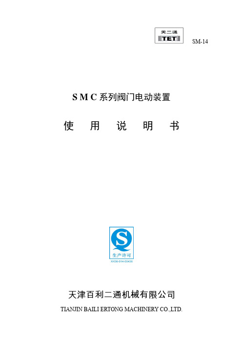
SM-14S M C系列阀门电动装置使 用 说 明 书天津百利二通机械有限公司TIANJIN BAILI ERTONG MACHINERY CO.,LTD.目 录第一部分 SMC系列普通型产品使用说明第二部分 SMC系列整体型产品使用说明第三部分 SMC系列隔爆型产品使用说明第四部分 SMC-04~SMC-2低温型产品使用说明第一部分 SMC系列普通型产品使用说明1.概述SMC系列多回转型阀门电动装置(以下称电动装置)用于驱动控制阀瓣作直线运动的闸阀、截止阀、隔膜阀等多回转阀门。
SMC系列中的部分机座产品也可以同BA伞齿轮减速器或直齿轮减速器组合,形成SMC/BA等组合式多回转电动装置。
当SMC系列产品与HBC蜗轮减速器或JA行星减速器组合后则成为组合式部分回转电动装置,它用于驱动控制阀瓣作旋转运动的球阀、蝶阀、旋塞阀等部分回转阀门。
SMC系列电动装置可以远距离电动操作(控制室内操作),可以根据订货要求加装现场按钮灯盒,从而具备现场操作功能。
SMC系列产品的手动机构可完成现场手动操作阀门。
由于SMC/BA、SMC/HBC、SMC/JA等组合型式电动装置的控制、调节部件均在SMC系列产品上,所以本说明书同样适用于上述产品。
(图1)~(图9)所示为SMC、SMC/BA、SMC/HBC、SMC/JA普通型产品的外形主视图。
上述产品的外形和法兰连接尺寸可参见我公司有关产品样本。
所用电动装置的输出转矩、转速、转圈数、电动机功率等详见该电动装置的铭牌。
2.基本技术参数产品符合GB/T24923-2010《普通型阀门电动装置技术条件》2.1动力电源:380V、50Hz(特殊订货可提供220V、415 V、440 V、460 V、480 V、660 V、690 V,50Hz、60Hz)三项正弦交流电(根据用户要求,某些规格可提供单相220V电源的电动机)。
2.2外壳保护等级:IP65~IP67(IP68订货时提出)2.3使用环境温度:-20℃~70℃(根据用户订货要求)2.4环境相对湿度:≤90%(25℃时)2.5海拔高度:≤1000m2.6短时工作:时间定额为10、15、30min(根据电动机负载情况而定)2.7无强烈振动工况。

NOTE•The direct current power supply to be used should be UL approved as follows:Circuit (of Class2) which is of maximum 30 Vrms (42.4 V peak), with UL1310Class2 power supply unit or UL1585 Class2 transformer.•The product is a approved product only if it has a mark on the body.•Do not use with a corrosive or inflammable gas or liquid. (ISE70 Series)•Do not use SUS630, SUS430 and SUS304 for a corrosive or inflammable gasor liquid. (ISE75/ISE75H Series)Digital Pressure SwitchOperation ManualISE70/ISE75(H)Thank you for purchasing an SMC ISE70/ISE75(H) Series Digital Pressure Switch.Please read this manual carefully before operating the product and make sure you understand its capabilities and limitations.Please keep this manual handy for future reference.To obtain more detailed information about operating this product, please refer to the SMC website (URL ) or contact SMC directly.These safety instructions are intended to prevent hazardous situations and/or equipment damage.These instructions indicate the level of potential hazard with the labels of"Caution", "Warning" or "Danger". They are all important notes for safety and must be followed in addition to International standards (ISO/IEC) and other safety regulations.OperatorSafety InstructionsPipingPiping connectionConnect the piping to the fitting.When piping, tighten to an appropriate torque of 13.6 to 15 Nm for ISE70 series and 25 to 28 Nm for ISE75/75H series.Other SettingsFine adjustment mode (Fine adjustment function of display value)Peak / Bottom hold display Key lock Zero clearTo set each of these functions, refer to the SMC website(URL ) for more detailed information, or contact SMC.Mounting and InstallationTroubleshootingIndication LED (Green): Displays the switch condition. LED is ON when theoutput (OUT1) is turned ON.LCD display: Displays the current status of pressure, setting mode and errorcode. Four display modes can be selected: display always in red or green, or display changing from green to red, or red to green,according to the output status.UP button: Selects the mode or increases the ON/OFF set value.Press this button to change to the peak display mode.DOWN button: Selects the mode or decreases the ON/OFF set value.Press this button to change to the bottom display mode.SET button: Press this button to change to another mode and to set a value.∗: This picture applies to all output specifications except -27 and -67.(If the output specification shown in a part number is -27 or -67, the Indication LED OUT2 (Red) is added.)Connector mounting / removalInsert the lead wire with connector with reference to key grooves.Tighten the connector by hand using the knurl, rotating clockwise.1234Brown White Blue BlackDC(+)OUT1 (PNP)DC(-)OUT1(NPN)Output -431234Brown White Blue BlackDC(+)NC DC(-)OUT1 (PNP)Output -27/-671234Brown White Blue BlackDC(+)OUT2 (NPN or PNP)DC(-)OUT1 (NPN or PNP)SettingFunction SettingInitial settingor longer.The display shown to the right will appear to allow initial settings.To complete the initialization and proceed to measurement mode, press the SET button continuously for 2 seconds, or this will happen automatically if no buttons are pressed for 30seconds.If the hysteresis is set to 2 digits or less, the switch output may chatter if the input pressure fluctuates near the set value.Normally open modeON OFFHigh pressureSwitch outputNormally closed modeON OFFHigh pressureSwitch output Hysteresis modeIn hysteresis mode, [H_1] and the set value of hysteresis will be displayed in turn, for [P_1] or [n_1]. Press the SET button to return to thenormal measurement mode. Press the UP or DOWN button to enter the value change mode. (See "Value setting")Refer to the product catalogue or SMC website(URL ) for more information about wiring.Refer to the product catalogue or SMC website (URL )for more information about settings.Pressure SettingPressure input mode for OUT1Press the SET button inmeasurement mode to display set values. [P_1] or [n_1] and thecurrent set value will be displayed in turn. Press the SET button to display the next set value.(Hysteresis: H_1) Press the UP orDOWN button to enter the value change mode. (See "Value setting")Normally closed Normally openDisplays in turnMaintenanceError Indicationcontact SMC.∗: Only for the output specifications -27 and -67.Displays in turn Window comparator modeTo set each of these functions, refer to the SMC website(URL ) for more detailed information, or contact SMC.How to reset the product after a power cut or forcible de-energizing The setting of the product will be retained as it was before a power cut or de-energizing.The output condition is also basically recovered to that before a power cut or de-energizing, but may change depending on the operating environment.Therefore, check the safety of the whole installation before operating the product. If the installation is using accurate control, wait until the product has warmed up (approximately 20 to 30 minutes).It is possible to return to measurement mode from any setting item by pressing the SET button for 2 seconds or longer.Note: Specifications are subject to change without prior notice and any obligation on the part of the manufacturer.© 2011 SMC Corporation All Rights ReservedAkihabara UDX 15F , 4-14-1, Sotokanda, Chiyoda-ku, Tokyo 101-0021, JAP AN Phone: +81 3-5207-8249 Fax: +81 3-5298-5362URL SpecificationsOutline with Dimensions (in mm)Refer to the product catalogue or SMC website (URL ) for more information about the product specifications and outline dimensions.InstallationMountingInstall using a bracket (Model: ZS-31-A) available as an option.Mounting with bracketAssemble the bracket assembly and bracket B around the pipe fitting.Then, mount the product on a panel using M6 screws.Reinforce the mounting using M6 nuts etc. if the panel has a thickness of less than 5 mm.WiringConnectionConnections should only be made with the power supply turned off.Use separate routes for the Pressure switch wiring and any power or high voltage wiring. Otherwise, malfunction may result due to noise.Ensure that the FG terminal is connected to ground when using acommercially available switch-mode power supply. When a switch-mode power supply is connected to the product, switching noise will besuperimposed and the product specification can no longer be met. This can be prevented by inserting a noise filter, such as a line noise filter and ferrite core, between the switch-mode power supply and the product, or by using a series power supply instead of the switch-mode power supply.Refer to the product catalogue or SMC website (URL )for more information about mounting hole dimensions.Refer to the SMC website (URL ) for more information about troubleshooting.。