mastercam9.1练习题
- 格式:doc
- 大小:119.50 KB
- 文档页数:2
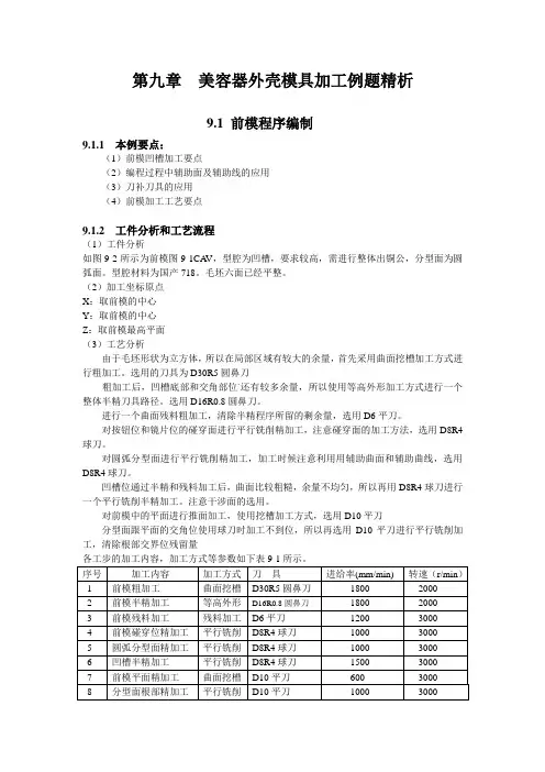
第九章美容器外壳模具加工例题精析9.1 前模程序编制9.1.1 本例要点:(1)前模凹槽加工要点(2)编程过程中辅助面及辅助线的应用(3)刀补刀具的应用(4)前模加工工艺要点9.1.2 工件分析和工艺流程(1)工件分析如图9-2所示为前模图9-1CA V,型腔为凹槽,要求较高,需进行整体出铜公,分型面为圆弧面。
型腔材料为国产718。
毛坯六面已经平整。
(2)加工坐标原点X:取前模的中心Y:取前模的中心Z:取前模最高平面(3)工艺分析由于毛坯形状为立方体,所以在局部区域有较大的余量,首先采用曲面挖槽加工方式进行粗加工。
选用的刀具为D30R5圆鼻刀粗加工后,凹槽底部和交角部位`还有较多余量,所以使用等高外形加工方式进行一个整体半精刀具路径。
选用D16R0.8圆鼻刀。
进行一个曲面残料粗加工,清除半精程序所留的剩余量,选用D6平刀。
对按钮位和镜片位的碰穿面进行平行铣削精加工,注意碰穿面的加工方法,选用D8R4球刀。
对圆弧分型面进行平行铣削精加工,加工时候注意利用用辅助曲面和辅助曲线,选用D8R4球刀。
凹槽位通过半精和残料加工后,曲面比较粗糙,余量不均匀,所以再用D8R4球刀进行一个平行铣削半精加工。
注意干涉面的选用。
对前模中的平面进行推面加工,使用挖槽加工方式,选用D10平刀分型面跟平面的交角位使用球刀时加工不到位,所以再选用D10平刀进行平行铣削加工,清除根部交界位残留量表9-1美容器前模加工工步图9-1 加工步骤示意图9.1.3 程序编制步骤打开文件单击主功能表中档案→取档,在弹出的文件列表中选择正确的文件路径,并选择9-1.mc9文件,打开图形文件。
按F9键显示坐标系。
打开图层可以看到第一层是CA V,第二层是CORE,第三层是L1 ,第四层是L2 ,选择第一层,关掉其它层,然后确定,所以屏幕上只显示前模图。
将图素另存为9-1CA V.mc9。
绘制对角线,设置Z深度为最高面。
选择“回主功能表→绘图→直线→两点画线”捕捉到前模两个端点拉一条对角线。

Ⅰ、组织教学清点人数,安定课堂,集中学生思想,维持课堂纪律,掌握教学进程。
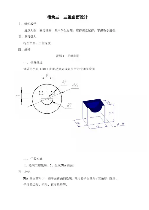
Ⅱ、复习引入构图平面、工作深度Ⅲ、新授课题1 平坦曲面一、任务描述试采用平坦(Flat)曲面功能完成如图所示卡通笑脸图二、任务实施1、绘制二维轮廓。
2、生成Flat曲面。
Ⅳ、小结Flat 曲面常用于一些平面曲面的绘制。
常用的平面图形:三角形、圆形、平行四边形、矩形、正多边形等。
Ⅰ、组织教学清点人数,安定课堂,集中学生思想,维持课堂纪律,掌握教学进程。
Ⅱ、复习引入构图平面、工作深度、平坦曲面(Flat)Ⅲ、上机练习课题1 平坦曲面一、任务描述试采用平坦(Flat)曲面功能完成如图所示书挡的曲面造形二、任务实施1、绘制二维轮廓。
2、生成Flat曲面。
Ⅳ、小结选择适当的构图平面绘制二维线框图、方位的确定。
Ⅰ、组织教学清点人数,安定课堂,集中学生思想,维持课堂纪律,掌握教学进程。
Ⅱ、复习引入牵引曲面的方向和倾斜角度Ⅲ、新授课题3 旋转曲面一、任务描述试采用旋转曲面功能完成如图所示不锈钢水漏的曲面造型二、任务实施1、绘制旋转二维轮廓。
2、生成旋转面。
3、曲面修剪。
Ⅳ、小结旋转曲面的生成、曲面的修剪方法Ⅰ、组织教学清点人数,安定课堂,集中学生思想,维持课堂纪律,掌握教学进程。
Ⅱ、复习引入旋转曲面的生成。
Ⅲ、上机操作课题3 旋转曲面一、任务描述试采用旋转曲面功能完成如图所示握力圈的曲面造型二、任务实施1、绘制旋转二维轮廓。
2、生成旋转面。
3、旋转复制、镜象。
Ⅳ、小结旋转曲面的生成、相同要素的复制Ⅰ、组织教学清点人数,安定课堂,集中学生思想,维持课堂纪律,掌握教学进程。
Ⅱ、复习引入旋转曲面的生成。
Ⅲ、新授课题4 扫描曲面一、任务描述试采用扫描曲面功能完成如图所示化妆盒的曲面造型。
二、任务实施1、绘制二维轮廓。
2、生成扫描曲面。
3、曲面倒圆角。
Ⅳ、小结扫描曲面的生成选项、曲面倒圆角法向确定。
Ⅰ、组织教学清点人数,安定课堂,集中学生思想,维持课堂纪律,掌握教学进程。
MasterCAM9后处理的修改MasterCAM系统缺省的后处理文件为,适用于FANUC(发那科)数控代码的控制器。
其它类型的控制器需选择对应的后处理文件。
由于实际使用需要,用缺省的后处理文件时,输出的NC文件不能直接用于加工。
原因是:以下内容需要回复才能看到⑴进行模具加工时,需从G54~G59的工件坐标系指令中指定一个,最常用的是G54。
部分控制器使用G92指令确定工件坐标系。
对刀时需定义工件坐标原点,原点的机械坐标值保存在CNC控制器的G54~G59指令参数中。
CNC控制器执行G54~G59指令时,调出相应的参数用于工件加工。
采用系统缺省的后处理文件时,相关参数设置正确的情况下可输出G55~G59指令,但无法实现G54指令的自动输出。
⑵后处理文件针对的是4轴加工中心,而目前使用量最大的是3轴加工中心,多出了第4轴数据“A0.”。
⑶不带刀库的数控铣使用时要去掉刀具号、换刀指令、回参考点动作。
⑷部分控制器不接受NC文件中的注释行。
⑸删除行号使NC文件进一步缩小。
⑹调整下刀点坐标值位置,以便于在断刀时对NC文件进行修改。
⑺普通及啄式钻孔的循环指令在缺省后处理文件中不能输出。
使用循环指令时可大幅提高计算速度,缩小NC文件长度。
如果要实现以上全部要求,需对NC文件进行大量重复修改,易于出现差错,效率低下,因此必须对PST(后处理)文件进行修改。
修改方法如下:1、增加G54指令(方法一):采用其他后处理文件(如)可正常输出G54指令。
由于后处理文件广泛采用,这里仍以此文件为例进行所有修改。
其他后处理文件内容有所不同,修改时根据实际情况调整。
用MC9自带的编辑软件(路径:C:\Mcam9\Common\Editors\Pfe\ )打开文件(路径:C:\Mcam9\Mill\Posts\ )单击【edit】→【find】按钮,系统弹出查找对话框,输入“G49”。
查找结果所在行为:pbld, n, *sgcode, *sgplane, "G40", "G49", "G80", *sgabsinc, e插入G54指令到当前行,将其修改为:pbld, n, *sgcode, *sgplane, "G40", "G49", "G80", *sgabsinc, "G54",e输出的NC文件修改前对应位置指令为:N102G0G17G40G49G80G90修改后变为:N102G0G17G40G49G80G90G54查找当前行的上一行:pbld, n, *smetric, e将其整行删除,或加上“#”成为注释行:# pbld, n, *smetric, e修改后G21指令不再出现,某些控制器可不用此指令。
![[VIP专享]Mastercam 练习题](https://uimg.taocdn.com/3b544792d5bbfd0a795673e1.webp)
一、绘制二维图形并进行尺寸标注。
取名: 班级-学号-D,例如,机电1班15号,则命名为“jd01-15-D”;机设1班15号,则命名为“js01-15-D”20分)
二、根据图2,利用MasterCAM绘制图形。
零件的毛坯108×58×10,加工路线:面铣削-外形铣削-挖槽加工(深10mm)-钻孔(通孔)。
取名: 班级-学号-M,例如,机电1
班15号,则命名为“jd01-15-M”;机设1班15号,则命名为“js01-15-M”(50分)
希望大家能多多练习,考试请勿作弊,一旦发现,成绩作废。
马上顶岗实习了,希望大家抓紧时间复习,希望各位每科考试都能通过。
平时出勤较少的同学上机练习请务必来,不会的好及时问老师,争取都过60分。
计划6月3,4号晚上考,地点待定,等通知。
![[VIP专享]mastercam 试卷](https://uimg.taocdn.com/78a116bfa5e9856a57126033.webp)
5.要让视图向左移动,应在键盘上按(C )键。
A.↑ B .↓ C.← D.6. 在Mastercam X4中,系统没有直接提供绘制( B )图素的命令。
A.直线 B.圆弧C矩形D圆7. 要设置图形的尺寸标注样式,应选择( D )菜单。
A. FileB. EditC. CreateD. Settings8. 对实体进行布尔运算有多种方式,但下列的( C )命令并不属于布尔运算命令。
A.并集B.交集C.逼近D.差集9. 对实体进行(D )操作时,需要指定方向。
A.并集运算B.实体圆角C.实体倒角D.修剪实体10. 下面选项中,不属于三维曲面加工方法的是(A )。
A.5轴曲面加工B.平行式精加工C.钻削粗加工D.外形铣削三、画图题(60分)1、在MasterCAM的mill模块中,参照如下三视图,要求将其绘制成立体图(20分)2、在MasterCAM的mill模块中,参照如下五角星三视图,要求将其绘制成曲面(40分)。
注意:其中五边形的外接圆直径200mm4. 要等距离复制图素,应使用(A )命令。
A.阵列B.旋转C平移 D.偏置6. 设置尺寸标注箭头的大小,应在Drafting Options对话框的()标签页中进行。
A.Dimension AttirbutesB.Dimension TextC.Note TextD.Leaders/Witness7. 一个串连图素在绕某直线旋转产生旋转曲面后,该串连图素将( C )。
A.被隐藏B.被删除C.还存在D.不一定8. 在绘制圆柱曲面时,其中心轴可用多种方式,但不包括以下( C )方式。
A.坐标轴B.直线C圆弧 D.未绘制的任意两点9. 将曲面上的一个孔洞补起来,成为一个统一的曲面,应该使用( D )命令。
A.去除边界B.填补孔洞C.分割曲面D.曲面融接10. 下列()命令可以在曲面的常参数方向上创建曲线。
A.绘制相交线B.创建分模线C.创建边界曲面D.创建曲面流线17. Mastercam X生成的加工程序,一般称为()。
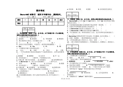
第 1页 共3页期末考试《MasterCAM 》试卷(C) 适用15年级专业:_数控技术_总分:100分 时间:100分钟15分。
以下每题只有一个正确答案,请将正确答案填写在相应位置。
) 1、下列哪项不属于构图平面( )A .前视图 B.俯视图 C .等角视图 D.侧视图 2、要让视图向左移动,应在键盘上按( )键A .↑B .↓ C.← D.→3、结束正在进行的操作,并返回上一级菜单的快捷键是( ) A 、End B 、Esc C 、F1 D 、F24、下列哪项不属于实体布林运算( )。
A. 结合B. 切割C. 挤出D. 交集 5、一个串连图素在绕某直线旋转产生旋转曲面后,该串连图素将 ( )。
.A.被隐藏B.被删除C.还存在D.不一定 6、对实体进行( )操作时,不需要指定方向。
A.并集运算B.牵引实体面C.实体抽壳D.加厚薄壁实体 7、在Mastercam 中,用户可以直接捕捉( )的中心点。
A .矩形 B.椭圆 C.正多边形 D.圆弧 8、对实体进行( )操作时,需要指定方向。
A.并集运算B.实体圆角C.实体倒角D.修剪实体 9、下面选项中,不属于三维曲面加工方法的是( )。
A.五轴曲面加工B.平行式精加工C.插削粗加工D.外形铣削 10、在绘制圆柱曲面时,其中心轴可用多种方式,但不包括以下( )方式。
A.坐标轴B.直线 C 圆弧 D.未绘制的任意两点1分,共10分。
请将正确答案填写在相应位置。
) 1、MasterCAM9.1分为 CAD 和CAM 两部分,其中CAD 部分即是计算机辅助设计部分。
( )2、任意线段是通过输入任意的两个端点绘制一条直线。
( )3、在进行外形铣削时选用的刀具是球刀。
( )4、在MasterCam 回复命令只能返回三次。
( )5、在MasterCam 中ESC 的作用是退出CAM 系统。
( )6、平行铣削加工是一种常用的加工方法,适合各种形态的曲面加工。
( )7、MasterCam 的图标菜单栏可以定制,可以删除,也可以增加。


2011–2012年度《Mastercam9.0》期末考试一、单项选择题1. 使用快速定位指令G00时,刀具整个轨迹不一定是直线,所以,要防止()。
(A) 定位不准现象(B) 停车困难现象(C) 刀具和工件或夹具干涉(D) 过冲现象2. 刀具角度中,对切削温度影响显著的是()。
(A)、刃倾角(B)后角(C)主偏角(D)前角3. 加工中心简称()(A)CNC (B)CIMS(C)CMC (D)FMS4. 加工中心与数控铣床和数控镗的主要区别是:( )。
(A)是否有自动排屑装置(B)是否有刀库和换刀机构(C)是否有自动冷却装置(D)是否具有三轴联动功能5. 装拆刀具必须()机器运转(A)开动(B)停止(C)可开动或停止(D)以上皆错6. 现代数控系统中的子程序( )嵌套。
(A)不能(B)可以无限层(C)可以有限层(D)只能有二层7.以下软件中,不属于模具计算机辅助设计软件的是()(A)pro/E (B)UG(C)Mastercam (D)AutoCAD8. 数控机床的操作中,在运行已调好的程序时,通常采用( )。
(A) JOG(点动)模式(B) AUTO模式(C) MDI模式(D)单段运行模式9. 产生加工误差的因素有()。
(A)工艺系统的几何误差(B)工艺系统的受力、受热变形所引起的误差(C)工件内应力所引起的误差(D)以上三者都是10. 测量反馈装置的作用是( )。
(A) 提高机床的定位精度、加工精度(B) 提高机床的灵活性(C) 提高机床的安全性(D) 提高机床的使用寿命11.机床验收检验自动换刀性能时,可通过手动和( )指令自动运行。
(A) M00 (B) MO3 (C) M04 (D) M0613. 工件的定位一般不采用()。
(A) 完全定位 (B) 不完全定位(C) 过定位 (D) 以上三者14.刀具半径补偿指令在返回零点状态是( )。
(A) 模态保持(B) 暂时抹消(C) 抹消(D) 初始状态15.合金工具钢具有较高的()。
1.masterCAM是美国CNC Software公司开发的基于PC平台的CAD/CAM软件。
2.数控机床在完成一道工序后刀具退到一定的高度,下一道工序以该点为起点,这一点是参考高度。
3.“构图面:3D”表示构图面是“空间绘图”。
4.“构图面:T”表示构图面是“俯示图”。
5.通过实体管理器,可以实现对实体的参数与图形进行修改与编辑。
6.通过视角管理可以设定工作坐标系WCS.7.快捷键F9表示坐标轴显示。
8.快捷键ALT+T表示刀具路径切换。
9.MasterCAM软件有四大模块,Mill 9.1属于数控铣。
10.重叠量设置可以避免进刀和退刀在同一个地点而产生加工痕。
11.左补正设置不属于补正形式。
12.一般挖槽设置不属于2D外型铣类型。
13.在2D外型铣削加工中,串联方向为顺时针,补正方向应该选择左补正。
14.在2D内型铣削加工中,串联方向为逆时针,补正方向应该选择右补正。
15.改变大小不属于改变图素的属性。
16.等高外形曲面粗加工的功能,沿曲面高度生成的粗加工刀具路径。
17.进给下刀位置又叫进给高度,刀具从安全高度以G00的速度快速下降到该点,改为以Z 轴的进给速率,向下加工工件。
18.布尔运算有结合、切割、交集等功能。
19.进给率是用来设置XY方向刀具的切割进给速度,单位为mm/min。
20.下刀速率用来设置Z方向刀具的切削进给速度。
21.外形铣削二维加工模组通常用于加工二维工件或三维工件的外形。
22.挖槽二维加工模组主要用来切除一个封闭图形所包围的材料或一个槽。
23.面铣削二维加工模组用于将工件表面铣削一定深度后为下一个加工作准备。
24.平行铣削曲面粗加工的功能:生成某一特定角度的平行切削粗加工刀具路径。
25.提刀速率用来设置Z方向刀具的向上提刀速度,此时刀具不切削,可以设置一个较大的速度。
26.举升实体是将两个或多个不同的封闭截面串联按顺序接而成的实体。
该实体既可以是独立的,也可以去切割或增加原有实体。
# Post Name : MPFAN# Product : MILL# Machine Name : GENERIC FANUC# Control Name : GENERIC FANUC# Description : GENERIC FANUC MILL POST# 4-axis/Axis subs. : YES# 5-axis : NO# Subprograms : YES# Executable : MP v9.10## WARNING: THIS POST IS GENERIC AND IS INTENDED FOR MODIFICATION TO# THE MACHINE TOOL REQUIREMENTS AND PERSONAL PREFERENCE.## --------------------------------------------------------------------------# Revision log:# --------------------------------------------------------------------------# Programmers Note:# CNC 01/12/01 - Initial post update for V8.1# CNC 07/02/01 - Add cantext to cancel drill and tool retract# CNC 01/09/02 - Initial post update for V9.0# CNC 01/31/02 - Set usecandrill, usecanpeck, force_wcs to YES# CNC 02/22/02 - Forces output of I,J,K arc centers (arcoutput:0)# CNC 04/12/02 - Use original position for inverse feed and 4 ax paths # CNC 05/01/02 - Set "helix_arc:2", support helix arc output in XY plane # CNC 05/07/02 - Do not update sav_rev with axis substitution# CNC 11/06/02 - Altered 'F'eedrate output format when tapping (G74/G84) # CNC 01/06/03 - moved feed assignment below pcom_moveb to address bugw/feed in 4 axis# CNC 01/17/03 - Added flags to allow reversal of axis orientations# CNC 02/04/03 - Initial post update for V9.1## --------------------------------------------------------------------------# Features:# --------------------------------------------------------------------------# This post supports Generic Fanuc code output for 3 and 4 axis milling.# It is designed to support the features of Mastercam Mill V9.## Following Misc. Integers are used:## mi1 - Work coordinate system# 0 = Reference return is generated and G92 with the# X, Y and Z home positions at file head.# 1 = Reference return is generated and G92 with the# X, Y and Z home positions at each tool.# 2 = WCS of G54, G55.... based on Mastercam settings.## mi2 - Absolute or Incremental positioning at top level# 0 = absolute# 1 = incremental## mi3 - Select G28 or G30 reference point return.# 0 = G28, 1 = G30##Canned text:# Entering cantext on a contour point from within Mastercam allows the # following functions to enable/disable.# Cantext value:# 1 = Stop = output the "M00" stop code# 2 = Ostop = output the "M01" optional stop code# 3 = Bld on = turn on block delete codes in NC lines# 4 = bLd off = turn off block delete codes in NC lines##Milling toolpaths (4 axis)#Layout:# The term "Reference View" refers to the coordinate system associated# with the Top view (Alt-F9, the upper gnomon of the three displayed).# Create the part drawing with the axis of rotation about the axis# of the "Reference View" according to the setting you entered for# 'vmc' (vertical or horizontal) and 'rot_on_x' (machine relative# axis of rotation).# vmc = 1 (vertical machine) uses the top toolplane as the base machine# view.# vmc = 0 (horizontal machine) uses the front toolplane as the base machine # view.# Relative to the machine matrix -# Rotation zero position is on the Z axis for rotation on X axis.# Rotation zero position is on the Z axis for rotation on Y axis.# Rotation zero position is on the X axis for rotation on Z axis.# The machine view rotated about the selected axis as a "single axis# rotation" are the only legal views for 4 axis milling. Rotation# direction around the part is positive in the CCW direction when# viewed from the plus direction of the rotating axis. Set the variable# 'rot_ccw_pos' to indicate the signed direction. Always set the work# origin at the center of rotation.##Toolplane Positioning:# Create the Cplane and Tplane as the rotation of the machine view about# the selected axis of rotation. The toolplane is used to calculate# the position of the rotary axis. This is the default setting.##3 Axis Rotary (Polar)# Polar positioning is offered in Mastercam 3 axis toolpaths through the# rotary axis options dialog. The selected toolpath is converted to angle # and radius position. The axis of rotation is forced to zero.##Axis substitution:# Use the Rotary axis substitution by drawing the geometry flattened# from the cylinder. The rotary axis button must be active for axis# substitution information to be output to the NCI file. The radius of# the rotary diameter is added to all the Z positions at output.##Simultaneous 4 Axis (11 gcode):# Full 4 axis toolpaths can be generated from various toolpaths under the# 'multi-axis' selection (i.e. Rotary 4 axis). All 5 axis paths are# converted to 4 axis paths where only the angle about the rotation axis# is resolved.##Drill:# All drill methods are supported in the post. See Simultaneous 4 Axis.##Additional Notes:# 1) Disable 4 axis by setting the numbered question 164. to 'n'.# 2) G54 calls are generated where the work offset entry of 0 = G54,# 1 = G55, etc.# 3) Metric is applied from the NCI met_tool variable.# 4) Incremental mode calculates motion from home position at toolchanges. # The home position is used to define the last position of the tool# for all toolchanges.# 5) The variable 'absinc' is now pre-defined, set mi2 (Misc. Integer) for # the 'top level' absolute/incremental program output. Subprograms are # updated through the Mastercam dialog settings for sub-programs.# 6) Always avoid machining to the center of rotation with rotary axis!# 7) Transform subprograms are intended for use with G54.. workshifts.## END_HEADER$## --------------------------------------------------------------------------# Debugging and Factory Set Program Switches# --------------------------------------------------------------------------m_one : -1 #Define constantzero : 0 #Define constantone : 1 #Define constanttwo : 2 #Define constantthree : 3 #Define constantfour : 4 #Define constantfive : 5 #Define constantc9k : 9999 #Define constantfastmode : yes #Enable Quick Post Processing, (set to no for debug)bug1 : 2 #0=No display, 1=Generic list box, 2=Editorbug2 : 40 #Append postline labels, non-zero is column position?bug3 : 0 #Append whatline number to each NC line?bug4 : 1 #Append NCI line number to each NC line?whatno : yes #Do not perform whatline branches? (leave as yes)skp_lead_flgs : 1 #Do NOT use v9 style contour flagsget_1004 : 1 #Find gcode 1004 with getnextop?rpd_typ_v7 : 0 #Use Version 7 style contour flags/processing?strtool_v7 : 2 #Use Version 7+ toolname?tlchng_aft : 2 #Delay call to toolchange until move linecant_tlchng : 1 #Ignore cantext entry on move with tlchng_aftnewglobal : 1 #Error checking for global variablesgetnextop : 0 #Build the next variable table# --------------------------------------------------------------------------# General Output Settings# --------------------------------------------------------------------------sub_level : 1 #Enable automatic subprogram supportbreakarcs : 2 #Break arcs, 0 = no, 1 = quadrants, 2 = 180deg. max arcs arcoutput : 1 #0 = IJK, 1 = R no sign, 2 = R signed neg. over 180arctype : 2 #Arc center 1=abs, 2=St-Ctr, 3=Ctr-St, 4=unsigned inc.do_full_arc : 0 #Allow full circle output? 0=no, 1=yeshelix_arc : 2 #Support helix arc output, 0=no, 1=all planes, 2=XY plane onlyarccheck : 3 #Check for small arcs, convert to linearatol : .01 #Angularity tolerance for arccheck = 2ltol : .002 #Length tolerance for arccheck = 1vtol : .0001 #System tolerancemaxfeedpm : 500 #Limit for feed in inch/minltol_m : .05 #Length tolerance for arccheck = 1, metricvtol_m : .0025 #System tolerance, metricmaxfeedpm_m : 10000 #Limit for feed in mm/minforce_wcs : yes #Force WCS output at every toolchange?spaces : 0 #Number of spaces to add between fieldsomitseq : no #Omit sequence numbers?seqmax : 9999 #Max. sequence numberstagetool : 0 #0 = Do not pre-stage tools, 1 = Stage toolsuse_gear : 0 #Output gear selection code, 0=no, 1=nomax_speed : 10000 #Maximum spindle speedmin_speed : 50 #Minimum spindle speednobrk : no #Omit breakup of x, y & z rapid movesprogname : 1 #Use uppercase for program name (sprogname)xflip : no #Reverse X axis orientation - eap 1/17/03 yflip : no #Reverse Y axis orientation - eap 1/17/03 zflip : no #Reverse Z axis orientation - eap 1/17/03# --------------------------------------------------------------------------# Rotary Axis Settings# --------------------------------------------------------------------------vmc : 1 #0 = Horizontal Machine, 1 = Vertical Millrot_on_x : 1 #Default Rotary Axis Orientation, See ques. 164.#0 = Off, 1 = About X, 2 = About Y, 3 = About Zrot_ccw_pos : 1 #Axis signed dir, 0 = CW positive, 1 = CCW positiveindex : 0 #Use index positioning, 0 = Full Rotary, 1 = Index only ctable : 5 #Degrees for each index step with indexing spindleuse_frinv : 1 #Use Inverse Time Feedrates in 4 Axis, (0 = no, 1 = yes ) maxfrdeg : 2000 #Limit for feed in deg/minmaxfrinv : 999.99#Limit for feed inverse timefrc_cinit : 1 #Force C axis reset at toolchangectol : 225 #Tolerance in deg. before rev flag changesixtol : .01 #Tolerance in deg. for index errorfrdegstp : 10 #Step limit for rotary feed in deg/min# --------------------------------------------------------------------------# Enable Canned Drill Cycle Switches# --------------------------------------------------------------------------usecandrill : yes #Use canned cycle for drillusecanpeck : yes #Use canned cycle for Peckusecanchip : yes #Use canned cycle for Chip Breakusecantap : yes #Use canned cycle for Tapusecanbore1 : yes #Use canned cycle for Bore1usecanbore2 : yes #Use canned cycle for Bore2usecanmisc1 : yes #Use canned cycle for Misc1usecanmisc2 : yes #Use canned cycle for Misc2# --------------------------------------------------------------------------# Common User-defined Variable Initializations (not switches!)# --------------------------------------------------------------------------xia : 0 #Formated absolute value for X incremental calculations yia : 0 #Formated absolute value for Y incremental calculations zia : 0 #Formated absolute value for Z incremental calculations cia : 0 #Formated absolute value for C incremental calculationscuttype : 0 #Cut type flag#0 = Tool Plane, 1 = Axis Subs, 2 = Polar, 3 = 4/5 axisbld : 0 #Block delete activeresult : 0 #Return value for functionssav_spc : 0 #Save spacessav_gcode : 0 #Gcode savedsav_absinc : 0 #Absolute/Incremental Saved Valuesav_coolant : 0 #Coolant savedsav_frc_wcs : 0 #Force work offset flag savedtoolchng : 1 #On a toolchange flagspdir2 : 1 #Copy for safe spindle direction calculation#Drill variablesdrlgsel : -1 #Drill Select Initializedrillref : 0 #Select drill referencepeckacel : 0 #Fractional percent to reduce peck2 when usecan.. : no drlgcode : 0 #Save Gcode in drillsav_dgcode : 0 #Drill gcode saved#Subprogram variablesmr_rt_actv : 0 #Flag to indicate if G51/G68 is active#0=Off, 1=Toolchange, 2=Subprogram call/start, G68#3=Absolute start, bothrt_csav : 0 #C saved valueend_sub_mny : 0 #Many tool setting captured at transform sub end#Rotary/Index variablescsav : 0 #C saved valueprvcabs : 0 #Saved cabs from pe_inc_calc,#Used for rotary feed and direction calculationscdelta : 0 #Calculation for angle changerev : 0 #Calculation for deg/minsav_rev : 0 #Saved revolution counterindx_out : c9k #Rotation direction calculationfmt 16 indx_mc #Rotation direction calculation#Vector Constants for Rotatary Calculationsaaxisx : 1 #A axis rotation vector constantaaxisy : 0 #A axis rotation vector constantaaxisz : 0 #A axis rotation vector constantbaxisx : 0 #B axis rotation vector constantbaxisy : 1 #B axis rotation vector constantbaxisz : 0 #B axis rotation vector constantcaxisx : 0 #C axis rotation vector constantcaxisy : 0 #C axis rotation vector constantcaxisz : 1 #C axis rotation vector constant#Feedrate calculation variablesfrdelta : 0 #Calculation for deg/minfrinv : 0 #Feedrate inverse timefrdeg : 0 #Feedrate deg/min actualprvfrdeg : 0 #Feedrate deg/min actualldelta : 0 #Calculation for deg/min, linearcldelta : 0 #Calculation for deg/min, linear and rotarycircum : 0 #Calculation for deg/minipr_type : 0 #Feedrate for Rotary, 0 = UPM, 1 = DPM, 2 = Inverse# --------------------------------------------------------------------------# Format statements - n=nonmodal, l=leading, t=trailing, i=inc, d=delta# --------------------------------------------------------------------------#Default english/metric position format statementsfs2 1 0.7 0.6 #Decimal, absolute, 7 place, default for initialize (:) fs2 2 0.4 0.3 #Decimal, absolute, 4/3 placefs2 3 0.4 0.3d #Decimal, delta, 4/3 place#Common format statementsfs2 4 1 0 1 0 #Integer, not leadingfs2 5 2 0 2 0l #Integer, force two leadingfs2 6 3 0 3 0l #Integer, force three leadingfs2 7 4 0 4 0l #Integer, force four leadingfs2 9 0.1 0.1 #Decimal, absolute, 1 placefs2 10 0.2 0.2 #Decimal, absolute, 2 placefs2 11 0.3 0.3 #Decimal, absolute, 3 placefs2 12 0.4 0.4 #Decimal, absolute, 4 placefs2 13 0.5 0.5 #Decimal, absolute, 5 placefs2 14 0.3 0.3d #Decimal, delta, 3 placefs2 15 0.2 0.1 #Decimal, absolute, 2/1 place (feedrate)fs2 16 1 0 1 0n #Integer, forced outputfs2 17 0.2 0.3 #Decimal, absolute, 2/3 place (tapping feedrate)# --------------------------------------------------------------------------#String and string selector definitions for NC output# --------------------------------------------------------------------------#Numbered question 164. string to detect Rotary axis y/nsq164#Address string definitionsstrm "M"strn "N"stro "O"strp "P"srad "R"srminus "R-"sblank#Cantext string definitions (spaces must be padded here)sm00 "M00"sm01 "M01"strtextnostrcantext#Transform mirror and rotate codesstrns_mir_on "G51.1" #Programmable mirror image codestrns_mir_off "G50.1" #Programmable mirror image cancel codestrns_rot_on "G68" #Coordinate System Rotationstrns_rot_off "G69" #Coordinate System Rotation Cancel# --------------------------------------------------------------------------# Error messages# --------------------------------------------------------------------------saxiswarn "WARNING-POST ROTARY AXIS ASSIGNMENT ('rot_on_x') OVERWRITTEN BY OPERATION"saxisoff "ERROR-POST ROTARY AXIS ASSIGNMENT ('rot_on_x') IS DISABLED"saxiserror "ERROR-INVALID ROTARY AXIS ASSIGNMENT ('rot_on_x') FOR CURRENT OPERATION"sindxerror "WARNING-INDEX ANGLE DOES NOT MATCH POST SETTING ('ctable')"stlorgerr "ERROR-TOOL ORIGIN DOES NOT MATCH CENTER OF ROTATION IN POLAR MILLING"shomeserror "ERROR-G92 WORK OFFSET ('mi1') DOES NOT SUPPORT TRANSFORM SUBPROGRAM"sprgnerror "ERROR-SUBPROGRAM NUMBER MATCHES THE MAIN PROGRAM NUMBER"# --------------------------------------------------------------------------# General G and M Code String select tables# --------------------------------------------------------------------------# Motion G code selectionsg00 G0 #Rapidsg01 G1 #Linear feedsg02 G2 #Circular interpolation CWsg03 G3 #Circular interpolation CCWsg04 G4 #Dwellsgcode #Target for stringfstrsel sg00 gcode sgcode# --------------------------------------------------------------------------# Select work plane G codesg17 G17 #XY plane codesg19 G19 #YZ plane codesg18 G18 #XZ plane codesgplane #Target stringfstrsel sg17 plane sgplane# --------------------------------------------------------------------------#Select english/metric codesg20 G20 #Inch codesg21 G21 #Metric codesmetric #Target stringfstrsel sg20 met_tool smetric# --------------------------------------------------------------------------#Select reference return codesg28 G28 #First reference point returnsg30 G30 #Second reference point returnsg28ref #Target stringfstrsel sg28 mi3 sg28ref# --------------------------------------------------------------------------# Cutter compensation G code selectionscc0 G40 #Cancel cutter compensationscc1 G41 #Cutter compensation leftscc2 G42 #Cutter compensation rightsccomp #Target for stringfstrsel scc0 cc_pos sccomp# --------------------------------------------------------------------------# Canned drill cycle string selectsg81 G81 #drill - no dwellsg81d G82 #drill - with dwellsg83 G83 #peck drill - no dwellsg83d G83 #peck drill - with dwellsg73 G73 #chip break - no dwellsg73d G73 #chip break - with dwellsg84 G84 #tap - right handsg84d G74 #tap - left handsg85 G85 #bore #1 - no dwellsg85d G89 #bore #1 - with dwellsg86 G86 #bore #2 - no dwellsg86d G86 #bore #2 - with dwellsgm1 G76 #misc #1 - no dwellsgm1d G76 #misc #1 - with dwellsgm2 G81 #misc #2 - no dwellsgm2d G82 #misc #2 - with dwellsgdrill #Target for stringfstrsel sg81 drlgsel sgdrill# --------------------------------------------------------------------------# Select incremental or absolute G codesg90 G90 #Absolute codesg91 G91 #Incremental codesgabsinc #Target stringfstrsel sg90 absinc sgabsinc# --------------------------------------------------------------------------# Feed mode G code selectionsg94 G94 #UPMsg94d G94 #DPM, See pfcalc_deg if you use another gcodesg93 G93 #Inversesgfeed #Target for stringfstrsel sg94 ipr_type sgfeed# --------------------------------------------------------------------------#Canned drill cycle reference heightsg98 G98 #Reference at inithtsg99 G99 #Reference at refhtsgdrlref #Target for stringfstrsel sg98 drillref sgdrlref # Drill cycle G string select# --------------------------------------------------------------------------# Generate string for spindlesm04 M4 #Spindle reversesm05 M5 #Spindle offsm03 M3 #Spindle forwardspindle #Target for stringfstrsel sm04 spdir2 spindle# --------------------------------------------------------------------------# Coolant M code selectionsm09 M9 #Coolant Offsm08 M8 #Coolant Floodsm08_1 M8 #Coolant Mistsm08_2 M8 #Coolant Toolscoolant #Target for stringfstrsel sm09 coolant scoolant# --------------------------------------------------------------------------# Table rotation direction# Table rotation direction, indexsindx_cw M22 #Rotate CW codesindx_ccw M21 #Rotate CCW codesindx_mc #Target for stringfstrsel sindx_cw indx_mc sindx_mc# --------------------------------------------------------------------------# Define the gear selection codeflktbl 1 3 #Lookup table definition - table no. - no. entries40 0 #Low gear range41 400 #Med gear range42 2250 #Hi gear range# --------------------------------------------------------------------------# Toolchange / NC output Variable Formats# --------------------------------------------------------------------------fmt T 4 t #Tool Numberfmt T 4 first_tool #First Tool Usedfmt T 4 next_tool #Next Tool Usedfmt D 4 tloffno #Diameter Offset Numberfmt H 4 tlngno #Length Offset Numberfmt G 4 g_wcs #WCS G addressfmt P 4 p_wcs #WCS P addressfmt S 4 speed #Spindle Speedfmt M 4 gear #Gear range# --------------------------------------------------------------------------fmt N 4 n #Sequence numberfmt X 2 xabs #X position outputfmt Y 2 yabs #Y position outputfmt Z 2 zabs #Z position outputfmt X 3 xinc #X position outputfmt Y 3 yinc #Y position outputfmt Z 3 zinc #Z position outputfmt C 11 cabs #C axis positionfmt C 14 cinc #C axis positionfmt C 4 indx_out #Index positionfmt R 14 rt_cinc #C axis position, G68fmt I 3 i #Arc center description in Xfmt J 3 j #Arc center description in Yfmt K 3 k #Arc center description in Zfmt R 2 arcrad #Arc Radiusfmt F 15 feed #Feedratefmt P 11 dwell #Dwellfmt M 5 cantext #Canned text# --------------------------------------------------------------------------#Move comment (pound) to output colon with program numbersfmt O 7 progno #Program number#fmt ":" 7 progno #Program numberfmt O 7 main_prg_no #Program number#fmt ":" 7 main_prg_no #Program numberfmt O 7 sub_prg_no #Program number#fmt ":" 7 sub_prg_no #Program numberfmt X 2 sub_trnsx #Rotation pointfmt Y 2 sub_trnsy #Rotation pointfmt Z 2 sub_trnsz #Rotation point# --------------------------------------------------------------------------fmt Q 2 peck1 #First peck increment (positive)fmt Q 2 shftdrl #Fine bore tool shiftfmt R 2 refht_a #Reference heightfmt R 2 refht_i #Reference height# --------------------------------------------------------------------------fmt "TOOL - " 4 tnote # Note formatfmt " DIA. OFF. - " 4 toffnote # Note formatfmt " LEN. - " 4 tlngnote # Note formatfmt " DIA. - " 1 tldia # Note format# --------------------------------------------------------------------------# Tool Comment / Manual Entry Section# --------------------------------------------------------------------------ptoolcomment #Comment for tooltnote = ttoffnote = tloffnotlngnote = tlngno"(", pstrtool, *tnote, *toffnote, *tlngnote, *tldia, ")", epstrtool #Comment for toolif strtool <> sblank,[strtool = ucase(strtool)*strtool, " "]pcomment #Comment from manual entry (must call pcomment2 if booleans) pcomment2pcomment2 #Comment from manual entryscomm = ucase (scomm)if gcode = 1007, "(", scomm, ")"else, "(", scomm, ")", e# --------------------------------------------------------------------------# Start of File and Toolchange Setup# --------------------------------------------------------------------------psof0 #Start of file for tool zeropsofpsof #Start of file for non-zero tool numberpcuttypetoolchng = oneif ntools = one,[#skip single tool outputs, stagetool must be onstagetool = m_one!next_tool]"%", e*progno, e"(PROGRAM NAME - ", sprogname, ")", e"(DATE=DD-MM-YY - ", date, " TIME=HH:MM - ", time, ")", epbld, n, *smetric, epbld, n, *sgcode, *sgplane, "G40", "G49", "G80", *sgabsinc, epbld, n, "M11A90.02", epbld, n, "M10", epbld, n, "M51", esav_absinc = absincif mi1 <= one, #Work coordinate system[absinc = onepfbld, n, sgabsinc, *sg28ref, "Z0.", epfbld, n, *sg28ref, "X0.", "Y0.", epfbld, n, "G92", *xh, *yh, *zh, eabsinc = sav_absinc]pcom_movebc_mmlt #Multiple tool subprogram callptoolcommentcommentpcanif stagetool >= zero, pbld, n, *t, "M6", epindexif mi1 > one, absinc = zeropcan1, pbld, n, *sgcode, *sgabsinc, pwcs, pfxout, pfyout,*speed, *spindle, pgear, strcantext, epbld, n, "G43", *tlngno, pfzout,epbld, n, "M51",epbld, n, "G0",pfcout, epbld, n, "M50",epbld, n, scoolant, next_tool, eabsinc = sav_absincpcom_moveatoolchng = zeroc_msng #Single tool subprogram callptlchg0 #Call from NCI null tool change (tool number repeats) pcuttypepcom_movebc_mmlt #Multiple tool subprogram callcommentpcanresult = newfs(15, feed) #Reset the output format for 'feed'pbld, n, sgplane, epspindchngpbld, n, scoolant, eif mi1 > one & workofs <> prv_workofs,[sav_absinc = absincabsinc = zeropbld, n, sgabsinc, pwcs, pfxout, pfyout, pfzout, epbld, n, "M51", epbld, n, "G0", pfcout, epbld, n, "M50", epe_inc_calcps_inc_calcabsinc = sav_absinc]if cuttype = zero, ppos_cax_linif gcode = one, plinoutelse, prapidoutpcom_moveac_msng #Single tool subprogram callptlchg #Tool changepcuttypetoolchng = oneif mi1 = one, #Work coordinate system[pfbld, n, *sg28ref, "X0.", "Y0.", epfbld, n, "G92", *xh, *yh, *zh, e]pbld, n, "M01", epcom_movebc_mmlt #Multiple tool subprogram callptoolcommentcommentpcanresult = newfs(15, feed) #Reset the output format for 'feed'pbld, n, *t, "M6", epindexsav_absinc = absincif mi1 > one, absinc = zeropcan1, pbld, n, *sgcode, *sgabsinc, pwcs, pfxout, pfyout,*speed, *spindle, pgear, strcantext, epbld, n, "G43", *tlngno, pfzout, scoolant, next_tool, epbld, n, "M51", epbld, n, "G0", pfcout, epbld, n, "M50", eabsinc = sav_absincpcom_moveatoolchng = zeroc_msng #Single tool subprogram callpretract #End of tool path, toolchangesav_absinc = absincabsinc = onesav_coolant = coolantcoolant = zero#cc_pos is reset in the toolchange herecc_pos = zerogcode = zeropcanpbld, n, sccomp, *sm05, psub_end_mny, epcan1, pbld, n, sgabsinc, sgcode, *sg28ref, "Z0.", scoolant, strcantext, e pbld, n, *sg28ref, "X0.", "Y0.", protretinc, epcan2absinc = sav_absinccoolant = sav_coolantprotretinc #Reset the C axis revolution counterif frc_cinit & rot_on_x,[rev = zerosav_rev = zerocabs = zerocsav = zeroindx_out = zeroif index, e, pindxcalc, pindexelse, *cabsprvcabs = zero!csav, !cabs]peof0 #End of file for tool zeropeofpeof #End of file for non-zero toolpretractcomment#Remove pound character to output first tool with staged tools #if stagetool = one, pbld, n, *first_tool, en, "M30", emergesubclearsubmergeauxclearaux"%", epwcs #G54+ coordinate setting at toolchangeif mi1 > one,[sav_frc_wcs = force_wcsif sub_level, force_wcs = zeroif workofs <> prv_workofs | (force_wcs & toolchng),[if workofs < 6,[g_wcs = 0 + 54*g_wcs]else,[p_wcs = 0"G54", *p_wcs]]force_wcs = sav_frc_wcs!workofs]pgear #Find spindle gear from lookup tableif use_gear = one,[gear = frange (one, speed)*gear]#Toolchange setuppspindchng #Spindle speed changeif prv_spdir2 <> spdir2 & prv_speed <> zero, pbld, n, *sm05, e if prv_speed <> speed | prv_spdir2 <> spdir2,[if speed, pbld, n, *speed, *spindle, pgear, e]!speed, !spdir2pspindle #Spindle speed calculations for RPMspeed = abs(ss)if maxss = zero | maxss > max_speed, maxss = max_speed#zero indicates spindle off (not a mistake)if speed,[if speed > max_speed, speed = maxssif speed < min_speed, speed = min_speed]spdir2 = fsg3(spdir)pq #Setup post based on switch settingsif stagetool = one, bldnxtool = one#Rotaxtyp = 1 sets initial matrix to top#Rotaxtyp = -2 sets initial matrix to frontif vmc, rotaxtyp = oneelse, rotaxtyp = -2#Shut off rotary axis if, Q164. Enable Rotary Axis button? n if ucase(sq164) = strn, rot_on_x = zeroif arctype = one | arctype = four,[result = newfs(two, i)result = newfs(two, j)result = newfs(two, k)]else,[result = newfs(three, i)。
MasterCAM9后处理的修改之巴公井开创作MasterCAM系统缺省的后处理文件为MPFAN.PST,适用于FANUC(发那科)数控代码的控制器。
其它类型的控制器需选择对应的后处理文件。
由于实际使用需要,用缺省的后处理文件时,输出的NC文件不克不及直接用于加工。
原因是:以下内容需要回复才干看到⑴进行模具加工时,需从G54~G59的工件坐标系指令中指定一个,最经常使用的是G54。
部分控制器使用G92指令确定工件坐标系。
对刀时需定义工件坐标原点,原点的机械坐标值保管在CNC控制器的G54~G59指令参数中。
CNC控制器执行G54~G59指令时,调出相应的参数用于工件加工。
采取系统缺省的后处理文件时,相关参数设置正确的情况下可输出G55~G59指令,但无法实现G54指令的自动输出。
⑵FANUC.PST后处理文件针对的是4轴加工中心,而目前使用量最大的是3轴加工中心,多出了第4轴数据“A0.”。
⑶不带刀库的数控铣使用时要去掉刀具号、换刀指令、回参考点动作。
⑷部分控制器不接受NC文件中的注释行。
⑸删除行号使NC文件进一步缩小。
⑹调整下刀点坐标值位置,以便于在断刀时对NC文件进行修改。
⑺普通及啄式钻孔的循环指令在缺省后处理文件中不克不及输出。
使用循环指令时可大幅提高计算速度,缩小NC文件长度。
如果要实现以上全部要求,需对NC文件进行大量重复修改,易于出现错误,效率低下,因此必须对PST(后处理)文件进行修改。
修改方法如下:1、增加G54指令(方法一):采取其他后处理文件(如MP_EZ.PST)可正常输出G54指令。
由于FANUC.PST后处理文件广泛采取,这里仍以此文件为例进行所有修改。
其他后处理文件内容有所分歧,修改时根据实际情况调整。
用MC9自带的编辑软件(路径:C:\Mcam9\Common\Editors\Pfe\PFE32.EXE)打开FANUC.PST文件(路径:C:\Mcam9\Mill\Posts\MPFAN.PST)单击【edit】→【find】按钮,系统弹出查找对话框,输入“G49”。