SmartTest 使用手册
- 格式:doc
- 大小:4.59 MB
- 文档页数:59

SmartInspect 智能检测喷码软件使用说明书(非接卡机版本)目录1概述......................................................................................................................................................................... 42安装软件................................................................................................................................................................. 43软件加密注册......................................................................................................................................................... 73.1安装加密狗 ................................................................................................................................................... 73.2注册软件 ....................................................................................................................................................... 74软件功能说明......................................................................................................................................................... 94.1主介面介绍 ............................................................................................................................................... 104.2文件 ........................................................................................................................................................... 104.2.1新建工程............................................................................................................................................... 104.2.2打开工程............................................................................................................................................... 114.2.3关闭工程............................................................................................................................................... 114.2.4导入设备参数....................................................................................................................................... 124.2.5保存设备参数....................................................................................................................................... 124.2.6退出 ...................................................................................................................................................... 134.3设备 ........................................................................................................................................................... 134.3.1设备管理............................................................................................................................................... 134.3.2检索模块............................................................................................................................................... 154.3.3读取模块............................................................................................................................................... 154.3.4喷码模块............................................................................................................................................... 154.3.5检测模块............................................................................................................................................... 164.3.6并行处理............................................................................................................................................... 174.3.7贴标模块............................................................................................................................................... 174.3.8剔除模块............................................................................................................................................... 174.3.9收料 ...................................................................................................................................................... 184.4运行 ........................................................................................................................................................... 184.4.1运行 ...................................................................................................................................................... 184.5数据 ........................................................................................................................................................... 184.5.1资料处理............................................................................................................................................... 184.5.2资料预处理........................................................................................................................................... 194.5.3补码重喷............................................................................................................................................... 194.5.4数据查询............................................................................................................................................... 194.5.5样式参数............................................................................................................................................... 204.5.6样式测试............................................................................................................................................... 224.6日志 ........................................................................................................................................................... 224.6.1日志查询............................................................................................................................................... 224.7用户 ........................................................................................................................................................... 234.8调试 ........................................................................................................................................................... 234.9显示 ........................................................................................................................................................... 234.9.1显示定义............................................................................................................................................... 234.9.2分页设置............................................................................................................................................... 244.10查看 ........................................................................................................................................................... 244.10.1工具栏.............................................................................................................................................. 244.10.2状态栏.............................................................................................................................................. 244.10.3下载工具条...................................................................................................................................... 244.10.4介面皮肤.......................................................................................................................................... 244.10.5介面定义.......................................................................................................................................... 254.11帮助 ........................................................................................................................................................... 254.11.1帮助主题.......................................................................................................................................... 254.11.2软件注册.......................................................................................................................................... 254.11.3关于SmartCard 智能卡喷码软件 ................................................................................................. 255设备参数............................................................................................................................................................. 265.1读取模块 ................................................................................................................................................... 265.1.1D8-C 或D8-U ...................................................................................................................................... 265.1.1.1卡片参数...................................................................................................................................................... 265.1.1.2卡片操作...................................................................................................................................................... 275.1.2奥阳CM-2FK ....................................................................................................................................... 295.2喷码模块 ................................................................................................................................................... 305.2.1激光机 .................................................................................................................................................. 305.3检测模块 ................................................................................................................................................... 311概述欢迎您使用“SmartInspect 智能检测喷码软件”,这是一套多功能智能卡个性化软件,可以个性化喷码、写数据。
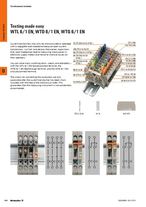
Testing made easyWTL 6/1 EN, WTD 6/1 EN, WTQ 6/1 ENCurrent transformers may only be short-circuited or operated with a negligible load impedance because open current transformers “run hot” and destroy themselves. Apart from that, load impedances lead to measuring inaccuracies in electricity supply meters and hence to financial losses for their operators.You can solve many switching tasks - clearly and affordably – with the WTL 6/1 EN test-disconnect terminal, theWTD 6/1 EN feed-through terminal, and the WTQ 6/1 EN cross-disconnect terminal.The screws for connecting the conductors are only accessible after the current transformer has been short-circuited with the help of the short-circuit slider. Thisguarantees that the measuring instrument is not accidentally disconnected.(7) STB 36.8/IH/BL WTL6/1(14) STB 21.6/45 SW (6)STB 36.8/IH/VI WTL6/1(8) BS 25 GE (2) WTD 6/1 ENWTL6/1WTL6/1STB 21.6/45 VI (13)WKS 2/3 (16)BS 25 VI (10)ISPF QB58 SW (18)STB 21.6/45 VH 16WAP WTLDT e r m i n a l s , W -S e r i e s1282250000 – 2012/2013Operating status(with external distribution of k-point)Example transformer using WTL 6/1 EN Comparison measurement for L1Operation depending on operating status:1. Connect ammeter to test sockets at terminal 2.2. Open disconnect slide link of terminals 2.3. Connect voltmeter to test sockets of terminals 7 and 10.Meter test for L1 through external power supplyOperation depending on operating status:1. Close the short-circuit slide of the terminals 1 and2.2. Open disconnect slide link of the terminals 2 and 7.3. C onnect external power supply to test sockets of terminals 1, 2 and 7, 10.Changing the meter for L1Operation depending on operating status:1. Close short-circuit slide of the terminals 1 and 2.2. Open disconnect slide link of the terminals 2 and 7.3. Disconnect meter for L1 at the terminals 1, 2 and 7.Operating condition with lockout device Testing condition with open disconnecting sliderOperating condition without lockout deviceExternal cross-bridgesDT e r m i n a l s , W -S e r i e s1282250000 – 2012/2013Testing made easyWTL 6/1, WTD 6/1, WTQ 6/1Sliding disconnector is easy to use (WTL 6/1)One short-circuit slider per terminal (WTL 6/1)Current transformers may only be short-circuited or operated with a negligible load impedance because open current transformers “run hot” and destroy themselves. Apart from that, load impedances lead to measuring inaccuracies in electricity supply meters and hence to financial losses for their operators.You can solve many switching tasks - clearly and affordably – with the WTL 6/1 test-disconnect terminal, theWTD 6/1 feed-through terminal, and the WTQ 6/1 cross-disconnect terminal.The screws for connecting the conductors are only accessible after the current transformer has been short-circuited with the help of the short-circuit slider. Thisguarantees that the measuring instrument is not accidentallydisconnected.One short-circuit jumper per terminal (WTQ 6/1)Safe disconnection of cross-connection (WTQ 6/1)(7) STB 25 IH/BL (14)STB 14/D6/4/M3 SAK10(2) WTD 6/1(3) WTL 6/1 (6)STB 25 IH/VI (5) STB 25 IH/GN (4) STB 25 IH/GE STB 35 IH/VI (13)STB 35 IH/SW VH 19WAP WTLDT e r m i n a l s , W -S e r i e s1282250000 – 2012/2013Operating status(with external distribution of k-point)Example transformer using WTL 6/1Comparison measurement for L1Operation depending on operating status:1. Connect ammeter to test sockets at terminal 2.2. Open disconnect slide link of terminals 2.3. Connect voltmeter to test sockets of terminals 7 and 10.Operation depending on operating status:1. Close the short-circuit slide of the terminals 1 and2.2. Open disconnect slide link of the terminals 2 and 7.3. C onnect external power supply to test sockets of terminals 1, 2 and 7, 10.Changing the meter for L11. Close short-circuit slide of the terminals 1 and2.2. Open disconnect slide link of the terminals 2 and 7.3. Disconnect meter for L1 at the terminals 1, 2 and 7.WTD 6/1 WTL 6/1DT e r m i n a l s , W -S e r i e s1282250000 – 2012/2013Convenient test-disconnect terminalsWTL 6/2, WTL 6/3All the circuits occurring in practice can be realised with the WTL 6/2 and WTL 6/3 terminals plus a few accessories. The short-circuit sliders are finger-touch safe – no risk of electric shock. Two cross-connections, e.g. for internal distribution of the contact point, can also be incorporated. The standard WQV 6 cross-connections of the W-Series can be used here, which also permit terminals to be bypassed.Thanks to the specially designed test sockets, bothconventional test plugs and conventional safety test plugs can be used with the WTL 6/3.Another advantage of the WTL 6/3 is that one screwdriver fits all screws and also all sockets.Variation with maximum accessories2 DEK markers per connection pointSafe test point according VGB 4Compact design: ➀ sliding disconnect,➁ cross-connection, ➂ short-circuit sliderOptimised accessories for all circuitvariations➁➀➂(3) SSP WTLWKS 1/2 (4)WQV 6/5 (11) DT e r m i n a l s , W -S e r i e s1282250000 – 2012/2013Operating status(with internal distribution of the k-point)Example transformer using WTL 6/3Comparison measurement for L1Operation depending on operating status:1. Connect ammeter to test sockets at terminal 2.2. Open disconnect slide link of terminals 2.3. Connect voltmeter to test sockets of terminals 7 and 10.Operation depending on operating status:1. Close the short-circuit slide of the terminals 1 and2.2. Open disconnect slide link of the terminals 2 and 7.3. C onnect external power supply to test sockets of terminals 1, 2 and 7, 10.Changing the meter for L1Operation depending on operating status:1. Close short-circuit slide of the terminals 1 and 2.2. Open disconnect slide link of the terminals 2 and 7.3. Disconnect meter for L1 at the terminals 1, 2 and 7.WTL 6/3/STB WTL 6/2The disconnect test terminal WTL 6/3/STB offers the same functionality as the WTL 6/2. However, thanks to the special design of the test sockets both conventional test plugs as well as commercially available test plugs can be used.DT e r m i n a l s , W -S e r i e s1282250000 – 2012/2013Testing made easy WTL 6 SL / WTD 6 SLCurrent transformers may only be short-circuited or operated with a negligible load impedance because open current transformers “run hot” and destroy themselves. Apart from that, load impedances lead to measuring inaccuracies in electricity supply meters and hence to financial losses for their operators.Many switching tasks can be done using the WTL 6 SLtest/disconnect terminals and the WTD 6 SL feed-through terminals.The screws for connecting the conductors are only accessible after the current transformer has been short-circuited with the help of the short-circuit slider. This guarantees that the measuring instrument is not accidentally disconnected.(9) STB 36.8/IH/BL WTL6/1 (8) STB21.6/45 SW(7)STB 36.8/IH/VI WTL6/1STB 21.6/45 DB VH 19WAP WTL6 SL Example transformer using WTL 6 SL / WTD 6 SLWTL 6 SL o. StB WTD 6 SL o. StBDTerminals,W-Series1282250000 – 2012/2013Testing made easyWTL 6 SL EN / WTD 6 SL ENCurrent transformers may only be short-circuited or operated with a negligible load impedance because open current transformers “run hot” and destroy themselves. Apart from that, load impedances lead to measuring inaccuracies in electricity supply meters and hence to financial losses for their operators.Many switching tasks can be done using the WTL 6 SL EN test/disconnect terminals and the WTD 6 SL EN feed-through terminals.The screws for connecting the conductors are only accessible after the current transformer has been short-circuited with the help of the short-circuit slider. Thisguarantees that the measuring instrument is not accidentally disconnected.Example transformer using WTL 6 SL EN / WTD 6 SL EN (9) STB 36.8/IH/BL (8) STB21.6/45 SW(7)STB 36.8/IH/VISTB 21.6/45 DB VH 19WAP WTL6 SLDT e r m i n a l s , W -S e r i e s1282250000 – 2012/2013STBCross-connection sliderType Qty.Order No.500169900000Cross-connection slider QVS …Connection sleeves VH 19 and fixing screws BS 25 (or sockets StB 35) are required for fastening the QVS in the individual terminals. The fixing screws have an insulating sleeve as colour marking and a screwdriver guide. Cross-connection sliders are designed so that the sockets inserted in the terminals remain available for test plugs at every position.The 2-pole version type QVS 2S is designed to slide with test plugs plugged in. If the option of testing is required when the QVS is plugged in, socket StB 35 can be used for fastening.The clearance and creepage sections required for the rated voltage of the terminal are changed when accessories are fitted.QVS 1Cross-connection sliderQVS QVS QVSK 2QVS 2SWTL6/1, WTD6/1WTL6/1, WTD6/1Cross-connection slider STBSockets type StB are screwed into the busbar of the terminal. They taketest plugs type PS4 or cross-connectors type QS2.DT e r m i n a l s , W -S e r i e s1282250000 – 2012/2013WQV / QL WQV(only for WTL 6/2, WTL 6/3)WKS / WKB WKS WKB QS 2BS / VH WQV cross-connectionsWQV cross-connections allow for finger and hand-safe connection betweenneighbouring terminals in accordance with VBG 4.QL cross-connection lugModel QL cross-connection links serve as fixed (i.e. non-switchable) cross-connections when used with WLT 6.1 test-disconnect terminals. They are fastened with connecting sleeves VH 12 and fixing screws BS M 3 x 20 (or sockets StB 30.5). The clearance and creepage distances required for the rated voltage of theterminal can be changed when accessories are installed. This applies in particular to the cross-connection of neighbouring terminals of differing potential.BS fixing screws VH connecting sleevesWKB / WKScross-connection bridgeWKB can be inserted from above in the case of cross-disconnect terminal type WTQ 6/1.The integrated disconnect slider is then responsible for connection or disconnection.QS2 cross-connection plug For sockets diameter 4 mm, for loads up to 44 A.DT e r m i n a l s , W -S e r i e s1282250000 – 2012/2013DIn hazardous area applications, the installation instructions and the ra-ted data specifications for accessories given in the technical appendix must be followed.Different current transformer circuits, e.g. for replacing measuring instruments or electricity meters, can berealised.Flexible / Flexible with ferrulemm²Tightening torque range (terminal screw)Stripping length / Blade size mm/-Width/Length/Height of lowest versionmm max. current / max. cond. cross-section A/mm²Max. clamping range mm²with socketEnd plate / Partition plateLockout device500300 (C)300 (D)3228 (C)10 (D)4AWG 26 (10)46 kV / 3A3 / V-00.5...4 / 0.5...40.4...0.7 Nm (M 2.5)10 / 0.6 x 3.5 mmIdentification systems (see assortment in catalogue 7)Marking tagsDEK 5/6500300 (D)150 (C)108 (D)8 (C)4AWG 26 (10)46 kV / 3A4 / V-00.5...6 / 0.5...40.5...0.8 Nm (M 3)10 / 0.6 x 3.5 mmWS 12/6T e r m i n a l s , W -S e r i e sTest-disconnect terminalsD630300 (C)300 (C)4145 (C)45 (C)6AWG 20 (8)66 kV / 3A5 / V-00.5...10 / 0.5...61...1.6 Nm (M 3.5)12 / 4.0 x 0.8 mmDEK 5/8 / WS 12/8630300 (C)300 (C)4145 (C)45 (C)6AWG 20 (8)66 kV / 3A5 / V-00.5...10 / 0.5...60.8...1.6 Nm (M 3.5)12 / 4.0 x 0.8 mmDEK 5/8 / WS 12/8500300 (C)300 (C)4145 (C)45 (C)6AWG 20 (8)66 kV / 3A5 / V-00.5...10 / 0.5...6(M 3.5)12 / 4.0 x 0.8 mmDEK 5/8 / WS 12/8T e r m i n a l s , W -S e r i e sTest-disconnect terminalsDIn hazardous area applications, the installation instructions and the ra-ted data specifications for accessories given in the technical appendix must be followed.Different current transformer circuits, e.g. for replacing measuring instruments or electricity meters, can beimplemented.Flexible / Flexible with ferrulemm²Tightening torque range (terminal screw)Stripping length / Blade size mm/-Width/Length/Height of lowest versionmm max. current / max. cond. cross-section A/mm²Max. clamping range mm²with socketEnd plate / Partition plateLockout device630300 (C)300 (C)4145 (C)45 (C)6AWG 20 (8)66 kV / 3A5 / V-00.5...10 / 0.5...61...1.6 Nm (M 3.5)12 / 4.0 x 0.8 mmIdentification systems (see assortment in catalogue 7)Marking tagsDEK 5/8 / WS 12/8T e r m i n a l s , W -S e r i e sTest-disconnect terminalsDIn hazardous area applications, the installation instructions and the ra-ted data specifications for accessories given in the technical appendix must be followed.Different current transformer circuits, e.g. for replacing measuring instruments or electricity meters, can berealised.Flexible / Flexible with ferrulemm²Tightening torque range (terminal screw)Stripping length / Blade size mm/-Width/Length/Height of lowest version mmmax. current / max. cond. cross-section A/mm²Max. clamping range mm²with socketEnd plate / Partition plateLockout device500300 (C)300 (C)4145 (C)45 (C)6AWG 20 (8)66 kV / 3A5 / V-00.5...10 / 0.5...61...1.6 Nm (M 3.5)12 / 4.0 x 0.8 mmIdentification systems (see assortment in catalogue 7)Marking tagsDEK 5/8 / WS 12/8500300 (C)300 (C)4145 (C)45 (C)6AWG 20 (8)66 kV / 3A5 / V-00.5...10 / 0.5...6(M 3.5)12 / 4.0 x 0.8 mmDEK 5/8 / WS 12/8T e r m i n a l s , W -S e r i e sTest-disconnect terminalsTest-disconnect terminalsWTL 6/4 FFLongitudinal - disconnectorWidth/Length/heightmm Max. current / max. cond. cross-sectionA/mm 2Max. clamping range mm 2WTD 6/4 FFFeed-throughDT e r m i n a l s , W -S e r i e sDIn hazardous area applications, the installation instructions and the ra-ted data specifications for accessories given in the technical appendix must be followed.Modular disconnect terminals enable circuits to be quickly isolated from the supply so that, for example, maintenanceor repair work can be carried out.Flexible / Flexible with ferrulemm²Tightening torque range (terminal screw)Stripping length / Blade sizemm/-Width/Length/Height of lowest version mm max. current / max. cond. cross-section A/mm²Max. clamping range mm²Standard32 x 100 x 68125 / 354 (35)24125350.8 kV / 3B9 / V-04...35 / 4...354 Nm (M 6)18 / 1.2 x 6.5 mmIdentification systems (see assortment in catalogue 7)Marking tagsWS 12/6Operation modeOperating mode• Slide link is closed• Auxiliary circuit is earthed • Display is illuminated greenTest positionWhen measuring insulation resistance with voltages greater than U Nom , the earth connection must first be disconnected .• Slide link is opened• Auxiliary circuit is not earthed • No earth fault• Display illuminated green and red with reduced intensit y• Disconnected earth connection -> When measuring insulation resistance with voltages greater than U Nom , the earth connection must be disconnected .Operational malfunction• Slide link is opened• Auxiliary circuit is not earthed • Earth fault• Display is illuminated re d24 V24 V24 VT e r m i n a l s , W -S e r i e sEarth wire disconnect terminalsDDistribution terminal with WQVIn hazardous area applications, the installation instructions and the ra-ted data specifications for accessories given in the technical appendix must be followed.N-busbars may not be used in certain applications (medical systems). Instead, installation terminals with adisconnector in the centre of the terminal can be used.Flexible / Flexible with ferrulemm²Tightening torque range (terminal screw)Stripping length / Blade sizemm/-Width/Length/Height of lowest version mm max. current / max. cond. cross-section A/mm²Max. clamping range mm²End bracket With “swifty set” cutting deviceStandard400300 (C)300 (D)2415 (C)10 (D)2.5AWG 22 (12)AWG 26 (12)4 kV / 3A3, A4 / V-00.5...4 / 0.5...2.50.4...0.6 Nm (M 2.5)8 / 0.6 x 3.5 mmIdentification systems (see assortment in catalogue 7)Marking tagsDEK 5/5 / WS 8/5400300 (C)300 (D)2415 (C)10 (D)2.5AWG 22 (12)AWG 26 (12)6 kV / 3A3, A4 / V-00.5...4 / 0.5...2.50.4...0.6 Nm (M 2.5)8 / 0.6 x 3.5 mmDEK 5/5 / WS 8/5T e r m i n a l s , W -S e r i e sInstallation terminalsD400300 (C)300 (D)2415 (C)10 (D)2.5AWG 22 (12)AWG 26 (12)4 kV / 3A3, A4 / V-00.5...4 / 0.5...2.50.4...0.6 Nm (M 2.5)8 / 0.6 x 3.5 mmDEK 5/5 / WS 8/5400300 (C)300 (D)2415 (C)10 (D)2.5AWG 22 (12)AWG 26 (12)4 kV / 3A3, A4 / V-00.5...4 / 0.5...2.50.4...0.6 Nm (M 2.5)8 / 0.6 x 3.5 mmDEK 5/5 / WS 8/5400300 (C)300 (D)2415 (C)10 (D)2.5AWG 22 (12)AWG 26 (12)6 kV / 3A3, A4 / V-00.5...4 / 0.5...2.50.4...0.6 Nm (M 2.5)8 / 0.6 x 3.5 mmDEK 5/5 / WS 8/5T e r m i n a l s , W -S e r i e sInstallation terminalsDDistribution terminals with 10 x 3 busbarIn hazardous area applications, the installation instructions and the ra-ted data specifications for accessories given in the technical appendix must be followed.Space-saving wiring of three-phase circuits using only twoterminals.Flexible / Flexible with ferrulemm²Tightening torque range (terminal screw)Stripping length / Blade sizemm/-Width/Length/Height of lowest version mm max. current / max. cond. cross-section A/mm²Max. clamping range mm²Busbar 10 x 3 (140 A)Rigid / flexible 0,5 - 6 / 4 mm²Rigid / flexible 6 - 16 mm²Flexible 16 - 35 mm²400300 (C)300 (D)2415 (C)10 (D)2.5AWG 22 (12)AWG 26 (12)4 kV / 3A3 / V-00.5...4 / 0.5...2.50.4...0.6 Nm (M 2.5)8 / 0.6 x 3.5 mmIdentification systems (see assortment in catalogue 7)Marking tagsDEK 5/5 / WS 8/5400300 (C)300 (D)2415 (C)10 (D)2.5AWG 22 (12)AWG 26 (12)6 kV / 3A3 / V-00.5...4 / 0.5...2.50.4...0.6 Nm (M 2.5)8 / 0.6 x 3.5 mmDEK 5/5 / WS 8/5T e r m i n a l s , W -S e r i e sInstallation terminalsD400300 (C)300 (D)2415 (C)10 (D)2.5AWG 22 (12)AWG 26 (12)4 kV / 3A3 / V-00.5...4 / 0.5...2.50.4...0.6 Nm (M 2.5)8 / 0.6 x 3.5 mmDEK 5/5 / WS 8/5400300 (C)300 (D)2415 (C)10 (D)2.5AWG 22 (12)AWG 26 (12)4 kV / 3A3 / V-00.5...4 / 0.5...2.50.4...0.6 Nm (M 2.5)8 / 0.6 x 3.5 mmDEK 5/5 / WS 8/5400300 (C)300 (D)2415 (C)10 (D)2.5AWG 22 (12)AWG 26 (12)6 kV / 3A3 / V-00.5...4 / 0.5...2.50.4...0.6 Nm (M 2.5)8 / 0.6 x 3.5 mmDEK 5/5 / WS 8/5T e r m i n a l s , W -S e r i e sInstallation terminalsDNeutral conductor disconnect terminalsIn hazardous area applications, the installation instructions and the ra-ted data specifications for accessories given in the technical appendix must be followed.These special modular terminals are specified for insulation measurements, without disconnecting the conductoraccording to VDE standards, for places of public assembly.Flexible / Flexible with ferrulemm²Tightening torque range (terminal screw)Stripping length / Blade size mm/-Width/Length/Height of lowest versionmm max. current / max. cond. cross-section A/mm²Max. clamping range mm²Blue WemidEnd bracketRigid / flexible 6 - 16 mm²Flexible 16 - 35 mm²400600 (C)600 (C)2425 (C)20 (C)2.5AWG 22 (12)AWG 26 (12)6 kV / 3A3 / V-00.5...4 / 0.5...2.50.4...0.6 Nm (M 2.5)10 / 0.6 x 3.5 mmIdentification systems (see assortment in catalogue 7)Marking tagsDEK 5/5 / WS 12/5400600 (C)600 (C)3235 (C)25 (C)4AWG 22 (10)AWG 26 (10)6 kV / 3A4 / V-00.5...6 / 0.5...40.5...1 Nm (M 3)10 / 0.6 x 3.5 mmDEK 5/5 / WS 12/5T e r m i n a l s , W -S e r i e sInstallation terminalsD400600 (C)600 (C)4145 (C)35 (C)6AWG 20 (8)AWG 26 (8)6 kV / 3A5 / V-00.5...10 / 0.5...60.8...1.2 Nm (M 3.5)12 / 4.0 x 0.8 mmDEK 5/5 / WS 12/5400600 (C)600 (C)5760 (C)50 (C)10AWG 16 (8)AWG 16 (6)6 kV / 3B6 / V-01.5...16 / 1.5...1612...20 Nm (M 4)12 / 1.0 x 5.5 mmDEK 5/5 / WS 12/5400300 (C)300 (C)7665 (C)65 (C)16AWG 14 (6)AWG 14 (6)6 kV / 3B7 / V-01.5...16 / 1.5...161.2...2.2 Nm (M 4)12 / 1.0 x 5.5 mmDEK 5/5 / WS 12/5T e r m i n a l s , W -S e r i e sInstallation terminalsDNeutral conductor disconnect terminalsIn hazardous area applications, the installation instructions and the ra-ted data specifications for accessories given in the technical appendix must be followed.These special modular terminals are specified for insulation measurements, without disconnecting the conductoraccording to VDE standards, for places of public assembly.Flexible / Flexible with ferrulemm²Tightening torque range (terminal screw)Stripping length / Blade size mm/-Width/Length/Height of lowest versionmm max. current / max. cond. cross-section A/mm²Max. clamping range mm²Blue WemidEnd bracketRigid / flexible 6 - 16 mm²Flexible 16 - 35 mm²400125356 kV / 3B8 / V-02.5...35 / 2.5...354...5 Nm (M 6)18 / 6.5 x 1.2 mmIdentification systems (see assortment in catalogue 7)Marking tagsDEK 5/5 / WS 12/5400600 (C)192175 (C)70AWG 6 (00)6 kV / 3B11 / V-010...70 / 10...7060...12 Nm (M 8)22 / S6 (DIN 6911)DEK 5/5 / WS 12/5T e r m i n a l s , W -S e r i e sInstallation terminalsDT e r m i n a l s , W -S e r i e sDIn hazardous area applications, the installation instructions and the ra-ted data specifications for accessories given in the technical appendix must be followed.A spring below the clamping yoke ensures there isadditional contact stability.Solid / strandedmm²Flexible / Flexible with ferrulemm²Width/Length/Height of lowest version mm max. current / max. cond. cross-section A/mm²Max. clamping range mm²Dark beige WemidDark beige Wemid (combi clip-on feet TS32/25)Black Wemid (combi clip-on feet TS32/25)Without STBEnd plate / Partition plate500600 (C)300 (C)2753230 (C)25 (C)284AWG 22...10AWG 22 (10)46 kV / 3A4 / V-0SIRA 02ATEX3242 U0.5...1.50.5...1.5 / 0.5...1.5Identification systems (see assortment in catalogue 7)Marking tagsWS 12/6500150 (C)300 (C)2754150 (C)45 (C)366AWG 20...8AWG 20 (8)66 kV / 3A5 / V-0SIRA 02ATEX3242 U0.5DEK 5/8 / WS 12/6,5T e r m i n a l s , W -S e r i e sTerminals with spring-loaded cable clampsD500150 (C)300 (C)2755750 (C)65 (C)5010AWG 16...8AWG 16 (610)6 kV / 3A5 / V-0SIRA 02ATEX3242 U1.5 (4)2.5...4 / 1 (4)DEK 5/5 / WS 12/6,5500300 (C)300 (D)3222 (C)10 (D)4AWG 22 (10)AWG 22 (10)6 kV / 3A4 / V-00.5...1.50.5...1.5 / 0.5...1.5DEK 5/6 / WS 12/6500300 (C)300 (D)3222 (C)10 (D)4AWG 22 (10)AWG 22 (10)6 kV / 3A4 / V-00.5...1.50.5...1.5 / 0.5...1.5DEK 5/6 / WS 12/6T e r m i n a l s , W -S e r i e sTerminals with spring-loaded cable clampsDIn hazardous area applications, the installation instructions and the ra-ted data specifications for accessories given in the technical appendix must be followed.A spring below the clamping yoke ensures there isadditional contact stability.Solid / strandedmm²Flexible / Flexible with ferrulemm²Width/Length/Height of lowest version mm max. current / max. cond. cross-section A/mm²Max. clamping range mm²Dark beige WemidDark beige Wemid (combi clip-on feet TS32/25)Black Wemid (combi clip-on feet TS32/25)Without STBEnd plate / Partition plate500600 (C)300 (C)2753230 (C)25 (C)284AWG 22...10AWG 22 (10)46 kV / 3A4 / V-0SIRA 02ATEX3242 U0.5...1.50.5...1.5 / 0.5...1.5Identification systems (see assortment in catalogue 7)Marking tagsWS 12/6500150 (C)300 (C)2754150 (C)45 (C)366AWG 20...8AWG 20 (8)66 kV / 3A5 / V-0SIRA 02ATEX3242 U0.5DEK 5/8 / WS 12/6,5T e r m i n a l s , W -S e r i e sTerminals with spring-loaded cable clampsD500600 (C)300 (C)2755750 (C)65 (C)5010AWG 16...8AWG 16 (610)6 kV / 3A6 / V-0SIRA 02ATEX3242 U1.5 (4)2.5...4 / 1 (4)DEK 5/5 / WS 12/6,5500300 (C)300 (D)3222 (C)10 (D)4AWG 22 (10)AWG 22 (10)6 kV / 3A4 / V-00.5...1.50.5...1.5 / 0.5...1.5DEK 5/6 / WS 12/6500300 (C)300 (D)3222 (C)10 (D)4AWG 22 (10)AWG 22 (10)6 kV / 3A4 / V-00.5...1.50.5...1.5 / 0.5...1.5DEK 5/6 / WS 12/6T e r m i n a l s , W -S e r i e sTerminals with spring-loaded cable clampsDIn hazardous area applications, the installation instructions and the ra-ted data specifications for accessories given in the technical appendix must be followed.A spring below the clamping yoke ensures there isadditional contact stability.Solid / strandedmm²Flexible / Flexible with ferrulemm²Width/Length/Height of lowest version mm max. current / max. cond. cross-section A/mm²Max. clamping range mm²Dark beige WemidDark beige Wemid (combi clip-on feet TS32/25)Black Wemid (combi clip-on feet TS32/25)Without STBEnd plate / Partition plate400300 (C)300 (D)6.3 6.3 (C) 6.3 (D)4AWG 22 (10)AWG 22 (10)6 kV / 3A4 / V-00.5...1.50.5...1.5 / 0.5...1.5Identification systems(see assortment in catalogue 7)Marking tagsDEK 5/6 / WS 12/65006/ 3A5 / V-0WS 12/6,5T e r m i n a l s , W -S e r i e sTerminals with spring-loaded cable clampsD5004166 kV / 3A5 / V-00.5WS 12/6,55004166 kV / 3A5 / V-00.5WS 12/6,55004166 kV / 3A5 / V-00.5WS 12/6,5T e r m i n a l s , W -S e r i e sTerminals with spring-loaded cable clamps。

Pfeiffer 氦质谱检漏仪——检漏领域新标准操作简单,性能一流工业自动化SmartTest 氦气检漏仪因其模块化设计,操作简单,外观现代等优势在真空检漏仪领域建立了新标准。
该款产品最重要的特点是结构坚固耐用,可靠性高,维修费用低 。
检漏仪的多种接口可供系统方便集成。
SmartTest 氦气检漏仪性能出众,安全可靠,以其快速可靠的检测结果,最小的可显示漏率以及较短的恢复周期而著称。
半导体制造 照明行业 制冷行业 光学镀膜模块化设计操作简便- 标准操作仅需启动/停止和置零 - 菜单驱动- 操作单元和远程控制在同一台设备中检漏仪能够实现动态跟踪,本底清零, 检测灵敏度高, 检测时间短 ;氦气检漏仪内置标准漏孔,自动校准;检漏仪器的氦清除时间短Pfeiffer 氦质谱检漏仪采用标准化组件配置,操作简易,性能出色,创建了真空领域检漏的新标准。
多样化的配置为不同的适用领域量身定做: 1. 配有旋片泵做前级泵的氦质谱检漏仪,适合于大多数检漏2. 配有干泵做前级泵的氦质谱检漏仪,适合无油检漏3. 无前级泵,应用于检漏系统 当被检腔体较大或含污染物时,可选择旁路。
此时,Pfeiffer 为您提供的远程控制器、小推车和吸枪等相关设备将有效发挥作用。
氦质谱检漏仪推车前级泵置零启动/停止吸枪模式真空模式可检测最小漏率< 5. 10-8 mbar l/s 可检测最小漏率< 5. 10-12 mbar l/s 检漏仪优点:1. 操作简单, 3 分钟即进入工作状态;2. 进气口起动压力高达 25 mbar, 缩短检测周期;3. 模块化设计, 便于维护和维修;3. 漏率值动态实时显示,本底清零, 灵敏度高, 检测时间短;4. 内置标准漏孔,自动校准;5. 本机氦清除时间短, 对氦气的抽速可达 2.5 l/s 。
技术参数:检漏仪前级泵抽速m3/h抽气时间 s 应用领域旋片泵干泵被检测体体积 半导体真空表面照明工业光学镀膜自动化制冷加速器制药包装型号抽速抽速0.5 l 10 l 100 lHLT 550 无————▲▲▲▲▲▲▲▲▲HLT 560 5 —145 590 ●●●▲▲●HLT 56530 —116 160 ●●●●▲▲含推车HLT 570 — 2 1125 1300 ●▲▲▲▲▲●HLT 572—7.5 135 410 ●▲▲▲▲▲▲▲▲含推车HLT 575—28 116 160 ●▲▲▲▲▲▲▲▲含推车●推荐使用▲可能实现尺寸及配件:技术参数:HLT 550-575可检测最小漏率< 5. 10-12 mbar l/s测试方式吸枪模式和喷枪模式可检测气体4He,3He,H2测漏范围10-12-1mbal l/s启动时间 3 min校准漏率棒吸枪喷枪小车吸枪模式测漏显示仪反应时间0.5 s法兰DN 25 ISO-KF最大进口压力25 mbar周围环境温度+10。
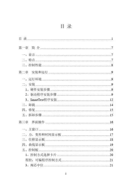
目录目录 (1)第一章简介 (7)一、前言 (7)二、特点 (7)三、控制性能 (8)第二章安装和运行 (9)一、运行环境 (9)二、安装 (9)1、硬件安装步骤 (9)2、驱动程序安装步骤 (9)3、SmartTest程序安装 (12)三、卸载 (14)四、修复 (15)五、拆卸步骤 (15)第三章界面操作 (16)一、主窗口 (16)二、力、变形和时间显示板 (17)三、位移显示板 (18)四、曲线显示板 (19)五、控制板 (20)1、控制方式选择卡片 (20)程控:可编程序控制方式 (21)3、阀芯中位 (21)4、位移控制调整位置 (23)5、位移控制 (24)6、力控制 (25)7、变形控制 (26)8、自定义程序控制 (26)六、刻度板 (26)七、数据板 (27)1、数据板窗口 (27)2、数据板工具栏 (27)3、数据库显示定位按钮 (28)八、数据分析 (28)第四章定制试验方法 (31)一、在配置工具箱中选择试验方法(定制1—定制20) (31)二、在软件主程序的数据板上选择【定制*】(最后一项) (31)三、定制试验方法 (32)四、定制试验方法的步骤 (33)五、部分功能概括 (34)1、内部定义 (34)2、字段 (35)第五章试验过程 (36)一、选择试验类型 (36)二、输入试件信息 (36)三、打开历史数据 (40)四、试验操作 (41)1、安装试件 (42)2、选择试验方法 (42)3、开始试验操作 (42)4、试验结束 (42)五、结果保存 (42)六、数据分析 (43)第六章报表的使用与制作 (44)一、报告打印(经典) (44)二、报表打印 (46)三、输出报表至O FFICE (50)1、新建模块 (50)2、Excel报表的制作(方法一) (52)3、Excel报表的制作(方法二) (55)4、曲线 (57)5、Word报表的制作 (58)6、Excel中求平均值 (59)7、Word求平均值 (60)第七章系统设置和调整 (61)一、系统参数 (61)1、系统 (61)2、显示 (62)3、曲线 (63)4、保护 (63)5、选项 (64)二、选择力传感器和引伸计 (64)三、校准、检定 (65)四、控制参数调整 (67)五、硬件测试 (69)六、控制观察 (69)第八章配置工具箱SMARTDEBUG使用说明 (70)一、安装和运行 (70)二、使用 (70)1、系统 (71)2、力传感器 (71)3、引伸计 (71)4、横向引伸计 (72)5、大变形 (72)6、位移 (72)7、控制 (72)8、选项 (73)9、试验方法 (74)10、外部控制 (75)第九章程序编制和程序执行 (76)一、用途 (76)二、程序执行 (76)三、程序编制 (76)1、控制程序的新建、删除和重命名 (76)2、加载方向 (77)3、程序内容 (77)4、编辑程序结构 (77)5、编辑程序内容 (78)6、编程实例 (81)第十章错误信息 (84)一、安装时 (84)二、启动时 (84)三、运行时 (85)附录:万能试验卡接线定义 (86)一、万能试验卡主要接线引脚定义 (86)二、电子万能接线方式 (87)1、J1、J2(DB-9)传感器、引伸计接线图 (87)2、J3(DB-25)接线图 (87)3、J4(DB-9)大变形接线图 (91)三、电液伺服万能试验机接线方式 (91)1、电液伺服控制器(比例阀) (91)2、电液伺服控制器(伺服阀) (92)3、其他接线 (93)四、试验机测控卡与板卡标识一览表: (93)第一章简介一、前言SmartTest程序根据不同的配置参数,适用于不同类型的材料试验机,如微机屏显万能试验机、微机控制电液伺服万能试验机、微机控制电液比例万能试验机以及微机控制电子万能试验机等。
目录目录 (1)第一章简介 (7)一、前言 (7)二、特点 (7)三、控制性能 (8)第二章安装和运行 (9)一、运行环境 (9)二、安装 (9)1、硬件安装步骤 (9)2、驱动程序安装步骤 (9)3、SmartTest程序安装 (12)三、卸载 (14)四、修复 (15)五、拆卸步骤 (15)第三章界面操作 (16)一、主窗口 (16)二、力、变形和时间显示板 (17)三、位移显示板 (18)四、曲线显示板 (19)五、控制板 (20)1、控制方式选择卡片 (20)程控:可编程序控制方式 (21)3、阀芯中位 (21)4、位移控制调整位置 (23)5、位移控制 (24)6、力控制 (25)7、变形控制 (26)8、自定义程序控制 (26)六、刻度板 (26)七、数据板 (27)1、数据板窗口 (27)2、数据板工具栏 (27)3、数据库显示定位按钮 (28)八、数据分析 (28)第四章定制试验方法 (31)一、在配置工具箱中选择试验方法(定制1—定制20) (31)二、在软件主程序的数据板上选择【定制*】(最后一项) (31)三、定制试验方法 (32)四、定制试验方法的步骤 (33)五、部分功能概括 (34)1、内部定义 (34)2、字段 (35)第五章试验过程 (36)一、选择试验类型 (36)二、输入试件信息 (36)三、打开历史数据 (40)四、试验操作 (41)1、安装试件 (42)2、选择试验方法 (42)3、开始试验操作 (42)4、试验结束 (42)五、结果保存 (42)六、数据分析 (43)第六章报表的使用与制作 (44)一、报告打印(经典) (44)二、报表打印 (46)三、输出报表至O FFICE (50)1、新建模块 (50)2、Excel报表的制作(方法一) (52)3、Excel报表的制作(方法二) (55)4、曲线 (57)5、Word报表的制作 (58)6、Excel中求平均值 (59)7、Word求平均值 (60)第七章系统设置和调整 (61)一、系统参数 (61)1、系统 (61)2、显示 (62)3、曲线 (63)4、保护 (63)5、选项 (64)二、选择力传感器和引伸计 (64)三、校准、检定 (65)四、控制参数调整 (67)五、硬件测试 (69)六、控制观察 (69)第八章配置工具箱SMARTDEBUG使用说明 (70)一、安装和运行 (70)二、使用 (70)1、系统 (71)2、力传感器 (71)3、引伸计 (71)4、横向引伸计 (72)5、大变形 (72)6、位移 (72)7、控制 (72)8、选项 (73)9、试验方法 (74)10、外部控制 (75)第九章程序编制和程序执行 (76)一、用途 (76)二、程序执行 (76)三、程序编制 (76)1、控制程序的新建、删除和重命名 (76)2、加载方向 (77)3、程序内容 (77)4、编辑程序结构 (77)5、编辑程序内容 (78)6、编程实例 (81)第十章错误信息 (84)一、安装时 (84)二、启动时 (84)三、运行时 (85)附录:万能试验卡接线定义 (86)一、万能试验卡主要接线引脚定义 (86)二、电子万能接线方式 (87)1、J1、J2(DB-9)传感器、引伸计接线图 (87)2、J3(DB-25)接线图 (87)3、J4(DB-9)大变形接线图 (91)三、电液伺服万能试验机接线方式 (91)1、电液伺服控制器(比例阀) (91)2、电液伺服控制器(伺服阀) (92)3、其他接线 (93)四、试验机测控卡与板卡标识一览表: (93)第一章简介一、前言SmartTest程序根据不同的配置参数,适用于不同类型的材料试验机,如微机屏显万能试验机、微机控制电液伺服万能试验机、微机控制电液比例万能试验机以及微机控制电子万能试验机等。
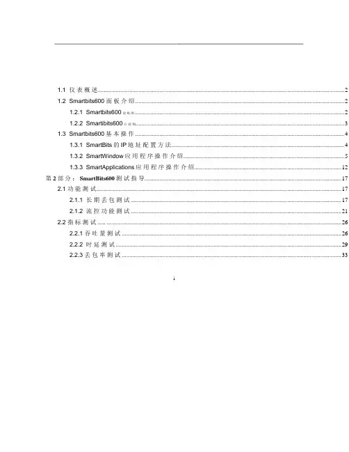
1.1 仪表概述 (2)1.2 Smartbits600 面板介绍 (2)1.2.1 Smartbits600前视图 (2)1.2.2 Smartibits600后视图 (3)1.3 Smartbits600基本操作 (4)1.3.1 SmartBits的IP地址配置方法 (4)1.3.2 SmartWindow应用程序操作介绍 (5)1.3.3 SmartApplications应用程序操作介绍 (12)第2部分: SmartBits600测试指导 (17)2.1 功能测试 (17)2.1.1 长期丢包测试 (17)2.1.2 流控功能测试 (21)2.2 指标测试..... (26)2.2.1 吞吐量测试 (26)2.2.2 时延测试 (29)2.2.3 丢包率测试 (33)i第1部分SmartBits600仪表使用1.1 仪表概述SmartBits系列测试仪是由NetCom System公司生产的,专门测试和分析网络性能的一种工具,SmartBits通过各种SmartCard的组合来实现对网络的测试、仿真和分析。
SmartBits600测试仪是其中的便携式设备,与SmartBits-6000B系统兼容,最多可插入两块测试卡,支持16个10/100M以太网端口。
1.2 Smartbits600 面板介绍1.2.1 Smartbits600前视图图1-1 Smartbits600前视图SmartBits600可配置2个LAN-3100A模块,支持16个10/100M以太网端口测试。
10/100 Ethernet SmartModule指示灯含意TX/PAUSE:绿灯:正常发送,黄灯:有流控包,红灯:有错包;RX/ERR:绿灯:数据包接收,DUPLEX/SPEED:绿灯:全双工,黄灯:半双工;1.2.2 Smartibits600后视图图1-2 Smartbits600后视图CONSOLE:串口,用于配置SmartBits的IP地址。

无人值守自动化变形监测信息系统Leito Auto Monitor System 操作使用手册四川徕拓科技发展有限公司二ОО八年一月·成都目录第一章系统简介 (1)1.1 系统性能与优点 (1)1.2 软件功能 (1)1.3 运行环境 (2)1.4 系统安装与删除 (2)1.4.1 硬件 (2)1.4.2 软件 (3)1.4.3 无线模块及域名等设置程序 (13)1.4.4 监控系统主程序的安装 (14)1.5 系统调试 (15)1.5.1 花生壳2008安装 (15)1.5.2 无线模块调试 (17)第二章系统界面 (21)第三章数据采集系统 (22)3.1 运行数据库SQL Server (22)3.2 运行数据库采集程序 (23)3.2.1 项目管理 (24)3.2.2 初始化 (25)3.2.3 测量设置 (26)3.2.4 定向 (29)3.2.5 目标定位 (30)3.2.6 开始测量 (32)第四章数据查询系统操作............................. .. (34)4.1 启动系统 (34)4.1.1 历史曲线 (34)4.1.2 历史数据 (35)4.1.3 信息查询 (37)技术支持 (39)第一章系统简介徕拓自动化变形监测测量系统由瑞士Leica公司自动型TCA系列的全站仪、Leica圆棱镜、自动变形监测软件、计算机及专用通讯供电电缆构成。
它集数据采集、分析及形变、位移值图形输出为一体。
能实现室外无人值守测量、按照预定的时间间隔自动采集数据、校核点(后视点)以及监测点位移超限检查及超限自动报警等功能。
是进行各类建筑物自动变形监测、滑坡监测、露天矿开采的理想系统。
1.1 系统性能与优点本系统采用自动化变形监测信息系统进行自动变形监测,其具有以下特点与优点:·建立高精度的基准点,采用实时差分式的测量方案,可以最大限度地消除或减弱多种误差因素,从而大幅度地提高测量结果的精度。
Swiss QualityHigh quality components paired with Swiss preci-sion engineering provide for a long product life and minimize costly machine downtime. In order to ensure maximum reliability of your SmartTest 50, all instruments are tested according to strict inter-nal quality standards before they leave our factory. Hardness TestingW ith more than 40 years of experience and more than 20'000 testers in the market, Dr. Schleuniger ® Pharmatron measuring technology is a safe invest-ment. Like all our hardness testers, the SmartTest 50 offers consistently accurate test results and fully complies with current USP (chapter 1217, tablet breaking force) and EP (2.9.8, resistance to crushing of tablets) requirements.Quality matters.C er t if i e d S y s t e mI S O9001SmartTest 50The SmartTest 50 sets new standards in fast and efficient semi-automatictesting of up to five physical parameters. Weight, thickness, width, diameter/length and hardness of virtually all tablet shapes can be tested in full compli-ance with current Pharmacopeia requirements. Proven Dr. Schleuniger®hardness measuring technology guarantees accurate and highly reliable testdata that can be evaluated immediately. An integrated color touch screen withsimple icon-based navigation makes operating the SmartTest 50 very intuitive consequently reducing operator training time to an absolute minimum. Per-fectly suited for both laboratory and production environments, the SmartTest50 has been designed to optimize efficiency of your quality control processwithout limiting the range of possible applications.→ SmartTest 50Semi-automatic tablet testing system→ Semi-automatic testing of virtually all tablet shapes and sizes with the SmartTest 50→ SmartAlign TM to measurediameter & hardness→ SmartAlign TM to measure width → SmartAlign TM to measurelength & hardnessThe SmartTest 50 is capable of testing virtually all tablet shapes and can easily be programmed to meet your individual testing requirements. Tablet samples are placed in a feeder carousel by the operator and all further testing is done automatically. The patented SmartAlign TMsystem guarantees reliable orientation of samples in the integrated measuring stations and automatically turns both oblong and oval shapes for width and length measuring prior to hardness testing.Smart, Smarter, SmartTest 50Especially when it comes to testing oval, oblong or other shapes, the SmartTest 50 combines maximum flexibility with reliable tablet orientation for high precision results. The integrated single-flap SmartAlign TM system ensures correct positioning of test samples at all times. As a standard, the SmartTest 50 first measures the width of tablets and then quickly re-positions them for precise length and hardness measuring – all in the same integra-ted measuring station. If width measuring is not required, tablets are immediately oriented for combined diameter (length) and hardness measurement.After each measurement, an integrated cleaning function removes debris and broken tablet fragments from all contact surfaces of the hardness station for trouble-free operation. Short cycle times are maintained at all times.To «future-proof» your investment, the SmartAlign TM system does not limit the application range of the SmartTest 50 in any way. From small to large tablet sizes – almost all shapes can be tested in standard configuration. When equipped with a custom feeder carousel, there are no limits for testing even the most complex specialtablet shapes.BCAAccommodating for most standard testing needs, up to 23 tablet samples are measured in one test run. If testing larger sample sizes is required, results from several test runs can be combined in a single test report – with the push of a button.Only the combination of quality components, state-of-the-art electronics and correct tablet orientation provides test results you can rely on. The SmartTest 50 with pro-ven Dr. Schleuniger ® Pharmatron measuring technology complies with all current USP and EP requirements and offers consistently accurate results. Tablet hardness is measured using a precision S-beam load cell with a line-arity of 99.95% over the entire measuring range. Featuring innovative light-weight construction, the integrated thickness gauge is extremely precise and applies only minimal pressure on tested tablets. To ensure stable test conditions – particularly for the integrated balance – the SmartTest 50 can be equipped with an anti-static safety cover protecting all measuring stations.Flexibility and Precision→ Top view of SmartTest 50 A: Integrated balance (depending on model) B: Thickness measuring stationC: Width / Length (Diameter) / Hardness measuring stationwith integrated SmartAlign TM system6Hardness testing → Semi-automatic tablet testing system →SmartTest 50→ Fast and intuitive icon-basedtouch screen operationOperating a semi-automatic tablet testing system has never been easier. The intuitive icon-based touch screen user in-terface sets new standards for fast and user-friendly control. Three test modes allow using the SmartTest 50 according to individual reporting requirements.From executing simple tests to programming products with T1/T2/PL limits and methods – everything is configurable using the touch screen menu. Intuitive icon-based navigation and logical menu structures with intelligent operator assistance provide for fast test setup, short training time and error-free data entry.Different views can be selected while test runs are executed, allowing theoperator to display currently measured value, complete series of measure-ments and even graphical hardness curves. Professional reports are auto-matically printed at completion of a test run.For paperless reporting and central data management in full compliance with 21 CFR, Part 11 requirements, the SmartTest 50 can be networked with the q-doc PC er-friendliness“FullTest” modeAll product and method specifica-tions can be pre-programmed and easily retrieved for fast test setup. Up to 100 products including nominal values and T1/T2/PL limits for all test parameters are conveniently stored directly on the SmartTest 50. Oncompletion of each test run, a com-prehensive report is printed automa-tically. The report shows all product and test parameters, calibration data and individually measured valuesalong with statistical analysis.“EasyTest” modeFor tests without T1/T2/PL limits, the “EasyTest” mode allows fast anduncomplicated setting of the desiredsample size for each parameter. No programming of product specifica-tions is required. The same reportingfunctions as in the “FullTest” mode are available.“SingleTest” modeTo quickly measure single tablets without printing a report, simply ac-tivate the parameter(s) you would like to test and press start.PC SoftwareAll SmartTest 50 tablet testers can be connected with PC software for 21 CFR, Part 11 compliant electronic data management. M easured results and test reports are collected in a data-base and can be exported in various formats such as PDF, XM L, HTM L, and TXT.→ Example: q-doc with 2 x SmartTest 50(TDH version and WTDH version)→ TDH version, connected to external balanceThe SmartTest 50 with external balance inter-face (instead of being equipped with an inte-grated weighing module) has been designed for alternative testing requirements.The operator first measures the weight of samples individually on a connected external balance and then places them in the SmartTest 50 feeder carousel. Measured results are automatically transferred to the tester. As soon as the required sample size has been reached, testing of thickness, width, diameter/length and hardness parameters proceeds automatically. Upon completion of the test, a report with all results – including manually measured weight values – is auto-matically generated.Models20014042016-01Your local sales & service partner1。
特种设备检验检测人员计算机考试系统操作手册以下是一个简要的操作手册:
《特种设备检验检测人员计算机考试系统操作手册》
1. 系统登录:打开考试系统,输入用户名和密码进行登录。
2. 考试信息:在登录后,查看考试相关信息,如考试科目、考试时间、考试规则等。
3. 答题操作:点击“开始考试”按钮进入答题界面。
系统将逐题显示考试题目,根据题目要求进行作答。
4. 标记功能:在答题过程中,可以使用标记功能对不确定的题目进行标记,以便后续检查。
5. 检查答案:在完成所有题目后,可以使用“检查答案”功能对已作答的题目进行检查和修改。
6. 提交试卷:确认无误后,点击“提交试卷”按钮提交考试结果。
7. 成绩查询:考试结束后,系统将自动计算并显示考试成绩。
考生可以查看自己的成绩和答题情况。
8. 退出系统:在完成考试后,点击“退出系统”按钮安全退出考试系统。

目录1.测试程序界面与参数设置 (2)3.测试程序操作 (12)一、 测试程序界面:1.0、双击桌面程序图标SateTestSYS v3.2(如图1所示),打开测试程序,程序自动运行:图12.0、程序运行至用户登录界面,如图2所示:图22.1、正确输入相应的用户名及密码,点击用户登录按钮(提示:密码最多只能输入三次,超过三次密码不正确,程序会自动退出并关闭系统),进入下一界面,如图3所示:图3a 管理员的登录界面图3b 一般用户的登录界面2.2、在图3界面,点击用户管理按钮,可以进行用户管理(此功能只对管理员开放),如图4所示,进入到图4界面时,可以对相应用户进行相关的编辑操作,如增加用户、删除用户等。
图42.3、在图3界面,如需要修改密码(只对当前用户有效),可点击修改密码进行修改,如图5所示:图52.4、在图3界面,如不需要进行其它操作,点击进入系统按钮,直接进入到测试系统测试页的界面,如图6所示:图62.4.1、 在测试系统的测试页,每个区域功能分别如图7标注所示:图72.4.2、1号区域窗口如图7:显示当前测试内容及每步骤的当前测试结果、状态。
2.4.3、2 号区域窗口如图7:包括用户信息:用户名、用户当前权限;UUT 信息:机种名称、产品条码、当前测试UUT/时间、当前在线时间、良品数量、不良品数量、测量总数量以及通过率等。
2.4.4、3号区域窗口如图7:显示信号线性波形状态。
2.4.4、4号区域窗口,有四个调试工具如图7,详细功能分别如下:A 、直通测试:如按下此按钮,在测试过程中遇到不良步骤,测试程序不会退出,直到测试完毕。
如果没按下此按钮,测试过程中遇到不良步骤,测试程序会自动退出,终止此次测试。
B 、单步测试:按下此按钮,开始测试,程序将进入单步测试模式,如图8所示,也即是说,点击一下确定按钮,就测试一步;在图8界面,还有一个重测当前步骤的复选框,此复选框如选中,只对当前步骤重测一次后,复选框清空,如需再次重测,必须再次选中此复选框。
Smart Tweezer LCR Meter Model: ST-5S-BT2, ST-5S and ST-5CIMPORTANT SAFETY INFORMATIONPlease read these instructions carefully before use and retain for future reference.• Please operate according to this manual, otherwise the protection provided by the device will be impaired or fail.• Check the condition before using. If you find any cracking, breakage, damage or abnormality, or you consider the device broken, stop using the device immediately • Do not store or operate the instrument at high temperature and high humidity environment.• Recharge the battery via USB when the display indicates the battery is getting low.• The meter powers off automatically after 60 seconds if not used.WARNING: Always discharge all capacitors before attempting measurement. WHAT’S INCLUDED• LCR Smart Tweezer style meter.• Storage holster.• Instruction manual.FEATURES• The LT5 range of professional quality, low cost LCR/ESR-meters are a perfect solution for testing, identifying components and troubleshooting electronic circuits.• The unique design combines a pair of tweezer like probes and a digital LCR-meter in one compact and lightweight device.• The gold-plated precision probes are designed to work with smallest SMT components.• It displays component type and value include a secondary parameter for capacitors and inductors. Automatic component identification and test frequency selectionsimplifies measurement by elimination unnecessary trial and error time.• Long battery life and extremely low sleep current makes this device and ideal choice for broad spectrum of applications.• Using it provides a quick and convenient way to test, sort and evaluate SMT components and perform on-board measurement and debugging. OPERATIONFUNCTIONSMeasurement functions:• AM - auto identification of L, C or R • L - inductance + resistance • C - capacitance + resistance• ESR - equivalent series resistanceTest frequency:• AF - auto selection of the optimal test frequency • Or 100Hz, 1kHz, 10kHz • Press the button twice to turn LCR meter on.• The device powers off automatically if it not operational for 60 seconds.• Once operational to change test frequency press the button.• To change measurement function press the button and hold it for 2 seconds.•To charge the device use a standard Micro USB lead and charger or connect to a computer.SPECIFICATIONS FeatureST-5S-BT2ST-5S ST-5CAutomatic component recognition P P P L,C,R measuring modes P P P ESR measuring mode P P PZ measuring mode P P Diode testingP P DCR measuring mode P P Component sorting P P Manual test override P P PVariable test signal level (0.5, 1.0 VRMS)(0.5, 1.0 VRMS)(0.5 VRMS)Auto offset subtraction P P OLED displayPPPAccuracy (typ) Resistance 0.2%0.2%0.5%Accuracy (typ) Capacitance 0.5%0.5% 1.0%Accuracy (typ) Inductance 0.5%0.5%1.0%Bluetooth PBattery life Up to 20 hours of continuous operation Charging time Up to 3 hours DC 5V 50mA micro USBDimensions 148 x 20 x 15mmWeight29gMAINTENANCECleaning the casing• Wipe using a damp cloth or sponge. Do not use solvents as these may damage the casing. Do not immerse in water.INFORMATION ON WASTE DISPOSAL FOR CONSUMERS OFELECTRICAL & ELECTRONIC EQUIPMENTThese symbols indicate that separate collection of Waste Electrical and Electronic Equipment(WEEE) or waste batteries is required. Do not dispose of these items with general householdwaste. Separate for the treatment, recovery and recycling of the materials used. Contact yourlocal authority for details of the battery and WEEE recycling schemes available in your area.Made in China. PR2 9PPMan Rev 1.0。
SmartTest 使用手册All Rights Reserved ,Copyright 2000-2009第一章SmartTest简介一. 前言SmartTest程序组根据不同的程序模块,适用于不同类型的材料试验机,如微机控制电液伺服万能试验机、微机屏显万能试验机、微机控制电子万能试验机以及微机屏显压力试验机等。
二. 特点(1)利用不同配置文件可以使一台主机配多个传感器。
(2)开放式的程序接口,可为用户定制特殊的试验方法,快速、便捷、可靠,缺省执行国标GB228-2002、GB7314-87试验方法,;(3)分档数码显示拉试验力和压试验力及峰值,精度为每档量程20%开始示值的±1%,可自动标定;(4)分4档数码显示变形,精度为每档量程20%开始±0.5%FS,可自动标定;(5)同时记录力-时间,变形-时间,力-变形和力-位移试验曲线,可随时切换观察,高速采样;(6)准确、完善的数据分析功能,采用人机交互方式分析计算测试材料的机械性能指标,可自动计算弹性模量、屈服强度、非比例伸长应力等,也可人工干预分析过程,提高分析的准确度;(7)试验数据采用数据库管理方式,自动保存所有试验数据和曲线。
(8)功能强大的报表编辑器,利用该报表编辑器,用户可以在极短的时间内做出自己想要的任何格式的报表,做报表不再是一件痛苦的事。
第二章SmartTest的安装和启动一、SmartTest的安装1、微机硬件配置◆PII C300/64M内存以上PC机,SVGA彩色显示器(支持800*600或以上显示分辨率),鼠标◆各种打印机2、微机操作系统◆中文WINDOWS95/98/me/2000/XP操作系统3、安装步骤1、将SmartTest安装光盘放入光盘驱动器,找到光盘根目录下的Setup.exe,双击执行它即可进行安装。
稍等片刻,就会出现一个初始化界面自动开始安装。
请选择“下一步”2、接下来出现安装目录设置窗口,程序缺省安装到C:\ProgramFiles\SmartTest目录下,除非必要,请不要改变安装目录,直接选择“下一步”3、在安装准备就绪窗口选择“下一步”,安装向导将开始复制安装文件到硬盘。
三思LD22单柱电子万能试验机操作手册万能试验机操作规程该仪器紧要适用于金属丝、金属箔、塑料、食品包装、纺织纤维、电线电缆、粘胶剂、接插件等行业的拉伸、剥离、撕裂等试验。
规格: 50、100、200、500 N、1、2、5 kN型号: LD22.501、LD22.102、LD22.202、LD22.502、LD22.103、LD22.203、LD22.503主机机架接受高精度、预加载的滚珠丝杠,提高了传动效率和位移精度。
接受高强度光杠固定上横梁及工作台面,构成高刚性的框架结构。
夹具操作便利,夹持牢靠的各种材料的专用夹具。
变形测量系统搭配应变式电子引伸计、精度高、响应快的测量系统,实现金属材料小变形的高精度测量。
电子引伸计按标距和变形量备有多种规格,可充分不同类型、不同形状的材料测量使用。
试验力测量装置接受高稳定性、高精度应变式力传感器,配以高稳定测量系统保证全程辨别力不变,确保试验力示值相对误差极限在 0.50% 以内。
可使用多个力传感器,实现宽范围的试验力测量。
急停机掌控开关在碰到意外情况下,能够牢靠的锁定设备。
掌控传动系统接受进口全数字式交流伺服器,掌控高精度、高响应频率的交流伺服电机,保证传动系统效率高、噪音低、传动平稳,并保证速度示值相对误差极限在0.20% 以内。
变形测量系统夹持式自动跟踪大变形测量系统,接受高精度进口传感器实现对塑料橡胶等非金属材料较大变形量的测量。
试验掌控盒具有横梁移动速度慢上/慢下、快上/快下、试样保护及运行功能。
电气测控系统LAB—350 全数字闭环测控系统。
位移测量装置接受伺服电机所配光电编码器进行传移测量,位移辨别力zui 小可达0.015m。
(不同机型略有区分)微机系统接受品牌计算机作为主掌控机,完成整机试验参数的设定、工作状态掌控、数据采集、处理分析、显示打印试验结果等功能。
配有试验机专用 Windows 系统 LAB Test 中英文版智能化软件包,可依据国jia标准、国际标准或用户供应的标准测量各种材料的物理性能,并对试验数据进行统计处理和判定,然后输出各种要求格式的试验报告和特性曲线图样。
全智能化通用考试系统V5.0操作手册(考点服务器)青岛正日软件有限公司2009年12月目录一、系统概述 (4)1.1使用对象 (4)1.2全智能化通用考试系统V5.0(考点服务器)简介 (4)1.3全智能化通用考试系统V5.0(考点服务器)主要特性 (4)1.3.1安全性高 (4)1.3.2易用性好 (5)1.3.3运行效率高 (5)1.3.4稳定性高 (5)1.4全智能化通用考试系统V5.0(考点服务器)业务指南 (5)二、安装指南 (6)2.1系统要求 (6)2.2安装过程 (6)三、功能介绍 (9)3.1用户登录 (9)3.2系统主界面 (9)3.3考点注册 (10)3.3.1考生机注册 (11)3.4考前设置 (13)3.4.1试题数据导入 (14)3.4.2名单数据导入 (15)3.4.3生成试卷 (15)3.4.4监考教师登录 (16)3.4.5考试信息查看 (17)3.5考试管理 (18)3.5.1考场实时管理 (18)3.5.1.1启动考试/停止考试 (19)3.5.1.2查找 (20)3.5.1.3缺考情况管理 (20)3.5.1.4考生管理 (21)3.5.1.5考生信息 (21)3.5.1.6异常处理 (22)3.5.1.7强制收卷 (23)3.5.1.8考生延迟 (23)3.5.1.9成绩查看 (24)3.5.1.10计算机管理 (24)3.6考后处理 (26)3.6.1考试结果导出 (26)3.6.2考场情况导出 (27)3.6.3数据备份 (27)3.6.4数据清除 (28)3.6.5答卷数据合并 (29)四、常见问题及解答 (29)4.1服务器启动后考生机软件无法连接到服务器 (29)4.2试题数据导入时提示“试卷包格式与考点要求不匹配,无法导入!” (30)4.3试题数据导入时提示“试卷包与配置文件不一致,无法导入!” (30)4.4名单数据导入时提示“考试信息不完整【没有唯一标识】,请首先导入考试试卷包和配置文件后再导入考生名单!” (30)4.5名单数据导入时提示“该文件不是本次考试的名单文件!” (30)4.6启动软件时提示找不到“zrdata systemstate” (30)4.7在考试过程中,考点服务器突然断电,如何处理? (31)4.8考试进行过程中,能否退出“考场实时管理”界面执行其他功能? (31)4.9考生交卷后,“考场实时管理”界面中考生列表中显示“已交卷”,但记录显示为红色如何处理? (31)4.10每场考试结束都要必须执行考试结果导出吗? (31)4.11考试完成了部分场次后,服务器崩溃不能恢复,如何处理? (31)4.12监考老师在系统中登记一次就可以管理全部场次吗? (32)五、加密锁(加密狗)的使用方法 (32)一、系统概述1.1使用对象此系统使用对象为学校信息技术考试负责人以及信息技术教师。
SmartTest 使用手册All Rights Reserved ,Copyright 2000-2009第一章SmartTest简介一. 前言SmartTest程序组根据不同的程序模块,适用于不同类型的材料试验机,如微机控制电液伺服万能试验机、微机屏显万能试验机、微机控制电子万能试验机以及微机屏显压力试验机等。
二. 特点(1)利用不同配置文件可以使一台主机配多个传感器。
(2)开放式的程序接口,可为用户定制特殊的试验方法,快速、便捷、可靠,缺省执行国标GB228-2002、GB7314-87试验方法,;(3)分档数码显示拉试验力和压试验力及峰值,精度为每档量程20%开始示值的±1%,可自动标定;(4)分4档数码显示变形,精度为每档量程20%开始±0.5%FS,可自动标定;(5)同时记录力-时间,变形-时间,力-变形和力-位移试验曲线,可随时切换观察,高速采样;(6)准确、完善的数据分析功能,采用人机交互方式分析计算测试材料的机械性能指标,可自动计算弹性模量、屈服强度、非比例伸长应力等,也可人工干预分析过程,提高分析的准确度;(7)试验数据采用数据库管理方式,自动保存所有试验数据和曲线。
(8)功能强大的报表编辑器,利用该报表编辑器,用户可以在极短的时间内做出自己想要的任何格式的报表,做报表不再是一件痛苦的事。
第二章SmartTest的安装和启动一、SmartTest的安装1、微机硬件配置◆PII C300/64M内存以上PC机,SVGA彩色显示器(支持800*600或以上显示分辨率),鼠标◆各种打印机2、微机操作系统◆中文WINDOWS95/98/me/2000/XP操作系统3、安装步骤1、将SmartTest安装光盘放入光盘驱动器,找到光盘根目录下的Setup.exe,双击执行它即可进行安装。
稍等片刻,就会出现一个初始化界面自动开始安装。
请选择“下一步”2、接下来出现安装目录设置窗口,程序缺省安装到C:\ProgramFiles\SmartTest目录下,除非必要,请不要改变安装目录,直接选择“下一步”3、在安装准备就绪窗口选择“下一步”,安装向导将开始复制安装文件到硬盘。
4、加密锁驱动驱动程序的安装5、复制过程持续一段时间,最后出现安装成功的提示窗口。
SmartTest安装成功以后,在“开始”的“程序”里将出现“万能试验机测控系统”程序组,点击“SmartTest 主程序”即可执行程序。
6、文件清单(安装完毕后)1)缺省情况下,程序安装在C:\ProgramFiles\SmartTest目录下;二、启动用鼠标点击WINDOWS[开始]菜单里的[万能试验机微机测量控制系统],或直接点击桌面上的SmartTest图标,即可启动试验控制程序。
注意,开始试验操作和结束试验操作都必须按照一定的操作顺序,(下面按照各个功能模块顺序依次介绍,随着程序不断升级,各模块的外观也许有所改变,但其核心功能是不变的)三、卸载:打开控制面板,选择“添加/删除程序”,在程序列表中选择“SmartTest”,然后选择“卸载”,即可安全、快速地删除SmartTest。
第三章界面操作一、主窗口:主窗口是程序的控制中心,它负责管理各个功能窗口,并显示试样的基本信息和试验控制状态信息,用户试验时面对的就是这个窗口。
说明:说明:①菜单1.【模式】菜单:负责系统管理工作,如系统模式的切换。
1)试验模式:即试验控制模式,显示负荷、变形和位移测量值,启动和停止试验,记录试验曲线等等。
2)演示模式:重放以前的试验过程或模拟一次新的试验。
3)退出模式:退出SmartTest控制程序。
2.【设置】菜单:分为“控制参数”、“硬件参数”、“软件参数”、“调入配置文件”、“存储配置文件”等菜单项。
(如图所示)。
1)[控制参数窗口]:✧显示刷新周期:“显示板”以此处的设置为周期进行各种显示。
缺省设置为400ms。
“刷新周期”的设置应保证显示适合人的眼睛观察。
✧曲线采集周期:“曲线板”以此处的设置为周期进行试验曲线的记录。
缺省设置为400ms。
“曲线采集周期”不应设置的过小,否则,会记录过多不必要的重复点,而且占用很多系统资源。
✧曲线高速采集周期:在记录试验曲线的过程当中,对于某一阶段(如屈服阶段)可以进行高速采集。
此处的设置即为高速采集的周期。
✧曲线绘制最长时间:曲线最多记录30000个点,减小曲线采集周期可以延长曲线记录时间。
注:计算机与试验机之间是通过插在计算机中的万能试验卡作为中间环节联系在一起的。
作为数据采集系统的计算机,应实时准确的对试验过程进行记录。
计算机对试验过程记录的“步长”叫做采样周期。
SmartTest控制系统利用特殊技术实现了对采样周期的精确控制,最小采样周期可为2ms。
此处应严格区分“采样周期”与“显示刷新周期”和“曲线采集周期”的区别。
2)[硬件参数窗口]:✧负荷传感器量程:此处的参数应根据试验机主机上的传感器进行设置,注意单位是kN。
✧引伸计量程:此处的参数应根据系统配置的引伸计进行设置。
✧系统活塞行程:此处设定的活塞行程亦即曲线板中位移坐标的最大值。
对于无行程检测的试验机,此项无意义。
✧试验力滤波次数:缺省设置为10次,此处的滤波设置不是简单意义上的滤波,SmartTest利用特殊技术有效地保证了试验机力值的高精度、高稳定性。
如果外界环境特别恶劣时,可以适当提高滤波次数。
✧变形滤波次数:同上。
✧位移每脉冲对应的位移量:此处的参数是指进行位移采集时,每一个脉冲所对应的位移值,请根据具体情况进行设置。
✧信号放大参数:如图所示,该窗口的参数在压环标定后,会自动进行改变。
请注意,这些参数出厂时已调试完毕,请用户不要随意改动,以免产生不良后果。
并且用户在开始使用时,最好将这些参数记录备案,一旦计算机硬件故障或因其他意外而必须重新安装系统程序时,只需将这些参数复原即可。
而不必重新标定传感器参数。
当然,用户也可以通过操作配置文件来备份此处的参数。
具体见“关于配置文件”。
3)[软件参数窗口]:✧显示精度:有关示值显示的内容为:1)小数点后显示**位:在该选项下面的“自动”选框为“空”时,该项起作用,将控制“显示板”上试验力、变形和位移的显示位数。
2)自动:有关试验机标准对试验力、变形的显示精度有非常明确的规定,因此,选中此项,SmartTest将自动根据试验力、变形档位确定显示位数。
对于位移的显示亦有相关的规约。
✧自动换档:选中,则试验力、变形在试验过程中将自动换档,否则,系统处于手动换档状态。
做为操作人员,对要进行的试验通常有一个基本的判断,因此SmartTest缺省设置试验力不自动换档,从而最大程度地减少换档冲击以及系统延时。
自动换档时,当测量值大于当前档位量程时,程序会自动向大档位跳转。
但在压环标定的时,不允许自动换档。
✧破型判断:即试样破坏的判断条件,只有满足破型条件,软件才会自动结束试验。
其一根据力值下降的幅度和当前量程的比值来判断,这主要针对韧性高的试样或压缩试验,特点是力值是缓慢下降;第二个条件是根据力值突然下降的幅度来判断,主要针对拉伸试验,特点是试样断裂的瞬间,力值突然下降。
注意,只要满足上面任何一个条件,软件都会认为破型而自动结束试验。
注:此处的破型判断的设置起作用的前提条件是在试验力、变形面板中按下[破型判断]按钮。
✧采用拉伸旧标准:选中,采用的拉伸标准自动变为GB/T228-87,否则将采用GB/T228-2002。
利用此项功能可以在新旧拉伸标准之间进行切换。
✧关于试验力过载:当试验力大于一定的上限,系统将自动进入过载保护,并及时采取一定的措施,以保证试验机的安全。
过载分为两种情况:其一是试验力超过系统过载上限(最大量程*过载系数),其二为用户选择试验力不自动换档时(一般为压环标定传感器的时候),试验力大于当前量程的3%,程序也认为过载。
一旦程序认为试验力过载,会出现一个过载警告窗口。
这个窗口记录了本次过载的一些相关信息。
✧关于配置文件:如图所示,灵活地运用配置文件,可以任意配置多组传感器。
例如,系统需要分别配置50kN和100kN的传感器。
首先系统装配50kN的传感器,进行压环标定后,SmartTest的当前配置文件(即SmartTest.ini)记录的便是50kN传感器的校准参数。
然后,选择[存储配置文件]菜单,把当前的配置文件保存为一个有意义的文件名(如50kN.ini)。
系统装配100kN传感器后,重复上述过程。
此后,系统每次更换传感器后,只需选择[调入配置文件]菜单调入相应的传感器配置文件即可。
注:当前配置文件(即SmartTest.ini)是SmartTest正常运行的灵魂。
注:以上窗口中均有“修改”按钮,需要修改参数时,先点击“修改”按钮,只有输入了正确的权限密码,参数才能处于修改状态。
3.【调整】菜单:调整系统调试参数,一般在调试机器时使用,操作人员禁止使用,有权限密码保护。
✧校准窗口:如图所示,SmartTest系统可以通过软件数字精确调整负荷每档的采样显示值,在试验停止状态下,选择[调整]->[力传感器增益微调]菜单,将调出校准窗口。
校准方法:在输入框中输入或选择正确的标定值,当测力环达到标定值后,按下“校准”按钮,显示值将直接校准到标定值。
为了更方便的调整参数,在压环标定传感器时,即使在试验上行或下行状态下,也可以直接按[-]或[+]按钮来调整传感器放大增益,直到显示值和测力环所对应的力值一致。
如果切换档位,调试窗口也会同时切换。
调整负荷显示值时,请从最大档开始调整,因为第一档的调整将会影响后面各档。
注:变形的校准同负荷,此处不再敖述。
4.【工具】菜单:1)[报表编辑器]:参见”报表编辑器”一章。
2)[用户帐户]:参见附录“用户管理”。
5.【窗口】菜单:选择”锁定”后,“显示板”、“曲线板”、“控制板”作为一个整体进行移动。
选择“浮动”时,上述各窗口可以分别移动。
6.【帮助】菜单:提供系统操作的帮助信息和系统的相关信息。
7.【退出】菜单:退出SmartTest控制程序。
②系统状态栏:显示试验过程中试样和控制的相关信息,请用户随时留意状态栏中的提示信息,以避免盲目操作。
③系统工具栏:作用和系统菜单一样,但更便于用户选择;1.[试验]:切换到试验模式。
2.[分析]:切换到分析模式。
3.[数据板]: 点击可以弹出数据板窗口,具体参见“数据板”一节。
4.[前翻]:向前翻动数据记录。
5.[后翻]:向后翻动数据记录。
下面是一部分功能窗口的简要说明,后面将详细一一介绍:④试验力、变形显示板:试验力、变形的硬件调零、软件清零和显示,试验力峰值显示,试验力、变形档位的选择等。
⑤位移显示板:位移测量值的清零和显示以及横梁移动方向的指示。