爱默生 变频器说明书
- 格式:pdf
- 大小:1.85 MB
- 文档页数:20

产品信息变频器型号说明变频器铭牌说明变频器的铭牌说明如图所示:变频器铭牌变频器系列型号变频器系列型号见表所示:400V 系列变频器额定(380-480V ±10%)制动电阻的选择:*该建议的阻值为最低的阻值,通常可以按照该阻值的120%选择,这样就考虑到了制动电阻的热态和冷态的阻值的变化,通常需要制动电阻的阻值变化范围在5%。
** 制动功率通常可选曳引机功率的30%~40%,根据电梯的楼层高度和运行情况而定。
型号最大连续输出电流 (A )400V 时额定功率(KW)ES1405 7.6 3.0SIZE1ES1406 9.5 4.0 ES2401 135.5 ES2402 16.57.5 ES2403 25 11 SIZE2ES2404 29 13 ES3401 3215 ES3402 40 18.5 SIZE3 ES3403 46 22 ES4401 6030 ES4402 74 37 SIZE4 ES4403 9645型号 制动电阻的建议的最低阻值 (A )*制动电阻的建议的最小额定功率**(KW)ES1405 58 0.8SIZE1ES1406 58 1.2 ES2401 19 1.5 ES2402 19 2.0 ES2403 19 3.0 SIZE2ES2404 19 3.5 ES3401 184.0 ES3402 185.5 SIZE3 ES3403 186.0 ES4401 117.5 ES4402 11 9.0 SIZE4 ES4403 910变频器结构变频器的结构图选配件变频器的选配件如图所示:变频器的选配件图选配件表随机附件变频器随机配备一份UNIDRIVE ES 用户手册、安全手册、合格证及一个附件工具箱(包括表所列各项附件)。
变频器附件快速操作指南介绍变频器用户界面、菜单结构及安全级别。
键盘介绍键盘,显示器由两行水平排列的7段LED组成。
上排显示区显示变频器状态、当前菜单及所查看的参数编号。
爱默生变频器资料ES2402爱默生变频器资料ES24021. 简介本文档为爱默生变频器ES2402的资料介绍,包括其产品特点、技术参数、应用领域等内容。
2. 产品特点- 高性能:ES2402采用了先进的变频器技术,具有高效率、低能耗的特点,可广泛应用于各种工业控制领域。
- 可靠性:ES2402具有稳定可靠的工作性能,具备过载保护、过压保护等功能,能够保证设备的正常运行。
3. 技术参数- 输入电压:220V/380V- 输出电压:0~380V- 频率范围:0~400Hz- 控制方式:V/F,矢量控制- 额定功率:0.4kW~90kW- 过载能力:150%额定电流30s,180%额定电流1s4. 应用领域ES2402变频器广泛应用于以下领域:- 机械制造:如印刷设备、冶金设备、纺织设备等。
- 石化行业:如风机控制、泵控制等。
- 电力行业:如风力发电装置、水力发电装置等。
- 包装行业:如输送带、包装机械等。
5. 安装与调试ES2402变频器的安装与调试步骤如下:1. 确保输入电压与变频器额定电压相匹配。
2. 连接变频器的电源线,确保连接牢固可靠。
3. 连接变频器的输入电源和输出负载设备。
4. 打开变频器主电源,并设置相关参数。
5. 运行设备并对其进行调试,确保变频器工作正常。
6. 故障排除在使用ES2402变频器过程中,可能会遇到以下故障问题及其解决方法:- 故障一:变频器无输出电压。
解决方法:检查输入电源是否正常,检查输出负载是否故障,检查变频器是否设置正确。
- 故障二:变频器过载报警。
解决方法:降低负载电流,减少负载。
- 故障三:变频器过热报警。
解决方法:检查风扇是否正常运转,清理散热器,增加通风密度。
7. 维护保养ES2402变频器的维护保养工作包括以下内容:- 定期检查变频器的电缆连接是否紧固,是否有磨损现象。
- 定期清洁变频器的外壳,保持通风良好。
- 定期检查变频器的散热器,如果有堵塞,及时清理。
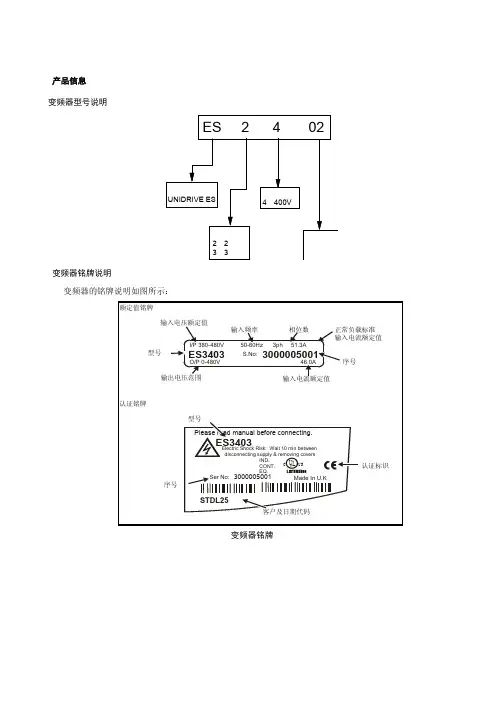
产品信息变频器型号说明变频器铭牌说明变频器的铭牌说明如图所示:变频器铭牌变频器系列型号变频器系列型号见表所示:400V 系列变频器额定(380-480V ±10%)制动电阻的选择:*该建议的阻值为最低的阻值,通常可以按照该阻值的120%选择,这样就考虑到了制动电阻的热态和冷态的阻值的变化,通常需要制动电阻的阻值变化范围在5%。
** 制动功率通常可选曳引机功率的30%~40%,根据电梯的楼层高度和运行情况而定。
型号最大连续输出电流 (A )400V 时额定功率(KW)ES1405 7.6 3.0SIZE1ES1406 9.5 4.0 ES2401 135.5 ES2402 16.57.5 ES2403 25 11 SIZE2ES2404 29 13 ES3401 3215 ES3402 40 18.5 SIZE3 ES3403 46 22 ES4401 6030 ES4402 74 37 SIZE4 ES4403 9645型号 制动电阻的建议的最低阻值 (A )*制动电阻的建议的最小额定功率**(KW)ES1405 58 0.8SIZE1ES1406 58 1.2 ES2401 19 1.5 ES2402 19 2.0 ES2403 19 3.0 SIZE2ES2404 19 3.5 ES3401 184.0 ES3402 185.5 SIZE3 ES3403 186.0 ES4401 117.5 ES4402 11 9.0 SIZE4 ES4403 910变频器结构变频器的结构图选配件变频器的选配件如图所示:变频器的选配件图选配件表随机附件变频器随机配备一份UNIDRIVE ES 用户手册、安全手册、合格证及一个附件工具箱(包括表所列各项附件)。
变频器附件快速操作指南介绍变频器用户界面、菜单结构及安全级别。
键盘介绍键盘,显示器由两行水平排列的7段LED组成。
上排显示区显示变频器状态、当前菜单及所查看的参数编号。
艾默生CTSK系列高性能可编程变频器用户手册第一篇范文:TD1000系列通用变频器艾默生TD1000系列通用变频器艾默生F0000运行频率设置方式选择F0001运行频率数字设置F0002运行命令选择F0003面板RUN运行方式F0004最大输出频率F0005STOP键功能选择F0006AVR功能选择F0007V/F曲线控制模式F0008转矩提升F0009.10加减数时间F0011.12上下限频率F0034起动频率F0039停机方式F0087额定频率F0088额定电压F0089额定电流F0102参数写人保护F0103参数初始化F0104用户密码若密码忘记可用同时按PRGSHIFTFUNC/DATA三键可清除密码EV1000、EV2000高性能通用型艾默生变频器G为恒转矩负载,P为风机水泵负载(EV1000:0.4-5.5KWEV2000:5.5-280KW)EV1000-2S0004G单相220VAC0.4KWEV1000-2S0007G单相220VAC0.75KWEV1000-2S0015G单相220VAC1.5KWEV1000-2S0022G单相220VAC2.2KWEV1000-4T0007G三相380VAC0.75KWEV1000-4T0015G三相380VAC1.5KWEV1000-4T0022G三相380VAC2.2KWEV1000-4T0037G三相380VAC3.7KWEV1000-4T0055G三相380VAC5.5KWEV1000-4T0037P三相380VAC3.7KWEV1000-4T0055P三相380VAC5.5KWEV2000-4T0055G/0075P5.5KW/7.5KWEV2000-4T0075G/0110P7.5KW/11KWEV2000-4T0110G/0150P11KW/15KWEV2000-4T0150G/1085P15KW/18.5KWEV2000-4T0185G1/0220P118.5KW/22KWEV2000-4T0220G1/0300P122KW/30KWEV2000-4T0300G1/0370P130KW/37KWEV2000-4T0370G/0450P37KW/45KWEV2000-4T0450G1/0550P145KW/55KWEV2000-4T0550G55KWEV2000-4T0750G75KWEV2000-4T0900G90KWEV2000-4T1100G110KWEV2000-4T1320G132KWEV2000-4T1600G160KWEV2000-4T2000G200KWEV2000-4T2200G220KWEV2000-4T0750P75KWEV2000-4T0900P90KWEV2000-4T1100P110KWEV2000-4T1320P132KWEV2000-4T1600P160KWEV2000-4T2000P200KWEV2000-4T2200P220KWEV2000-4T2800P280KWEV3000系列矢量艾默生变频器(2.2KW-220KW)EV3000艾默生变频器是高品质、多功能、低噪音的矢量控制通用变频器。
爱默生SP0404变频器说明书
变频器送电操作:
1.检查旁路柜隔离开关位置正确,各柜门封闭正常;
2.检查操作柱、变频器的急停按钮均复位,各柜门封闭正常;
3.合17G开关柜二次回路空开和保险,将断路器手车摇至工作位,并检查确认;
4.将17G开关柜转换开关切换至“远程”位;
5.送变频系统控制电源一自2#配电室Ⅱ-11柜7#抽屉;
6.合变频器和旁路柜所有二次回路空开和保险;
7.检查变频器人机界面,主控系统开始自检,控制面板上2个指示灯同时点亮;
8.主控所有自检通过后,允许运行灯(绿色)闪烁;
9.点击人机界面上进入系统按钮,输入密码后可进行参数的设置及监控;
10.将本地-远程选择开关拨至“本地”;
11.按下人机界面上预充电合闸按钮,变频器开始软启动,高压
指示灯(红色)常亮;
12.待软启动结束,自动闭合进线高压断路器,合闸成功后,高
压指示灯(红色)常亮;
13.将变频器“本地远程”开关切换至“远程”位;(变频启停
由操作柱和DCS实现);
变频器停电操作说明:
1.检查7#引风机已经停运,变频器确实处于停机状态;
2.按下17G开关柜“手分按钮”,分断6kV断路器,并摇至试验位;
3.断开17G开关柜二次回路空开和保险;
4.断变频系统控制电源一自2#配电室IⅡ-11柜7#抽屉;
注意:
1.电机运行时,打开变频器及旁路柜柜门,会连锁分断6kV断路器,导致停机;
2.电机运行时,断开旁路柜二次电源,会连锁分断6kV断路器,导致停机;
3.旁路柜的隔离开关只在倒闸时需要操作,正常运行期间不必频繁操作,否则会导致接触不良。
变频调速器(艾默生)使用说明感谢您购买盾安空调,为使您更好的使用和维护机组,提高机组的运行效率,延长机组的使用寿命,特请您注意以下几点:1、请您保管好随机资料,在开启或检修机器前,仔细阅读说明书及随机资料.2、安装工作及首次开机工作必须由受过训练的专业人员进行。
安装按电控柜铭牌的编号将其与机组编号一一对应的互相匹配.注意:请一一对应匹配.一、查收随机资料及附件1、附件:①尼龙接头;②包塑金属软管;③导线若干等。
二、柜体安装1、安装位置:控制柜安装机组旁边的墙壁上,如无墙壁,则用户自行做支架安装,建议安装位置与机组风机段距离≤3米,高度(以操作界面为准):1。
4~1.5米,接线出厂标配为3米,若接线距离>3米,则接线部分由用户自行解决。
2、安装方式:明装.采用壁挂式安装,安装孔及尺寸见电控柜实体.三、放线、接线、走线1、柜式空调机组电控柜固定完成后,按电机接线盒到电动机接线端子的弯曲距离放线。
2、按电气原理图、电气接线图、随机附件接好电源进线、接地线等导线。
3、若控制柜含BA干接点,则所需电缆用线由用户自备,建议使用线径0.75mm2导线。
调试(0。
7~5.5)kW变频器一、数字操作器TOP—LED02各部说明:PRG:编程键;FUNC/DATA:功能/数据键;>>:移位键;∧:递增键;∨:递减键;RUN:运行键;-1-STOP/RESET:停止/复位。
详细说明见随机变频器《使用手册》二、变频器内部参数设置注意:若Array变频柜含BA干接点,将选择开关打到自动档,通过远程常开无源输入触点对变频器启停进行控制,然后检测运行状态输出、手/自动状态输出的信号输出是否正常;带可选项参数为增加远程调频功能时设置参数,由用户自行确定,接收和反馈信号均为DC0~10V信号,出厂时不含此参数;出厂设置变频器跳码开关CN10跳为V.(7。
5~55)kW变频器一、数字操作器F1A452GZ1各部说明:MENU/ESC:编程/退出键;ENTER/DATA:功能/数据键;PANEL/REMOTE:运行命令通道切换键;>>:移位键;∧:递增键;-2-∨:递减键;JOG:点动键;RUN:运行键;STOP/RESET:停止/复位。

爱默生变频器调试说明一、电机自学习:第一步:检查接线无误第二步:调整以下变频器参数第三步:曳引机脱开负载第四步:打开抱闸电机可自由旋转第五步:闭合主输出接触器(在主输出接触器控制电路允许闭合的情况下,在电机开始自学习时变频器会自动输出主接触器吸合信号)第六步:将F1.11设为“1”后,按操作面板“RUN”键自学习开始,显示屏上显示“正在调谐”。
等待调谐结束显示屏上显示“自动调谐结束”。
(调谐过程中,如果出现异常可以按STOP/RESET终止调谐。
此时电机参数无效。
)二、检修运行第一步、检查变频器接线第三步、检查所有安全回路第四步、开始检修运行第五步、观察造作键盘七段显示电梯速度,与参数(F3.19)设定值是否相等,如果不等请调换编码器A相、B相接线。
三、井道自学习第一步:检查门区、上下限位、上下强迫减速信号、旋转编码器第二步:将电梯检修运行到底层低于门区位置关好门第三步:调整以下参数第四步:查看“F9.03”当前楼层是否为1,如不为1时用短接线先短接变频器COM端子与X1端子再与X2端子短接,然后查看当前楼层是否为1第五步:将微机设为自学习状态,电梯开始自动向上运行,运行到顶层自动停止。
自学习完毕。
第六步:查看“F4.09-F4.57)楼层高度脉冲数是否正确,如不正确重复以上操作。
四、快车试运行第一步:检查变频器Y1、Y2端子接线是否正确。
第二步、将电梯检修开关旋到正常位置,电梯位于自动状态,选层开始运行。
(注:先不要运行首层和顶层,先在中间层试运行)第三步:先试单层快车运行,再试多层运行。
查看减速点通过信号是否正常。
如果不正常调整“F4.02-F4.06”。
五:舒适感调整调整以下参数六:平层调整七:上下强迫减速的调整第一步:设定以下参数第二步:调整强迫减速开关位置(开关安装位置1.2倍额定梯速)第三步:调整F3.22得到所需要的强迫减速距离(应小于强迫减速开关安装距离)第四步:调整F7.11运行的到顶层、底层换速时有台阶感。
EMS-VVX ® 15-35DRIVE SYSTEMINSTRUCTION MANUAL GBV alid for the following models:EMS-VVX 15SEMS-VVX 15EEMS-VVX 25SEMS-VVX 25EEMS-VVX 35SEMS-VVX 35ESoftware version R1The product is protected as follows:Patents: US 4 868 478; EP 0 285 637; SE 8604308-0;US 5 315 224; EP 0 507 835; SE 9002217-9;SE 9902821-9Registered design: DE 400 05 393.4.Registered designs pending:SE 992 196; US 29/124 164Document number: 01-2157-01Edition: r2aDate of publication: 18 November 2002© Copyright Emotron AB 2002Emotron AB reserves the right to change without warning specifications in the text and in illustrations. The contents of this document may not be copied without the permission of Emotron AB.During installation•Read the instruction manual completely before installation and commissioning.•The installation must be carried out by qualified personnel. •General conditions and regulations for the installation and operation of electrical machinery must be observed. •Measures to protect against personal injury and damage to the machine must be taken following local rules and regulations. •The drive system EMS-VVX is intended for permanent installation.•Cables may not be connected or disconnected while the sup-ply voltage is on.•Check that the equipment is correctly connected before it is taken into use, see the instructions in the chapter on Mount-ing/Connection.•Faults that arise due to faulty installation or operation are not covered by the guarantee.During operation•Measurement in the control unit during operation may only take place at the connection terminal blocks. NOTE! Great care must be taken.•The units may not be opened or disassembled during opera-tion.During disassembly and scrapping•The housing of the control unit is made from aluminium and steel. The material must be handled and recycled following the relevant laws.•The circuit board contains small amounts of tin and lead, which must be handled and recycled in accordance with the relevant laws.•The motor is made from copper, plastic, aluminium and iron.These materials must be handled and recycled in accordance with the relevant laws.C O N T E N T S1. DESCRIPTION (5)1.1Introduction (5) (5)1.2 Productrange1.3 Operating indicators / built-in functions (6)2. MOUNTING/CONNECTION (10)2.1Mounting (10)2.2 Connection (11)3. MAINTENANCE/TROUBLESHOOTING (19)DATA (22)4. TECHNICAL4.1 Choice of size of drive system and belt pulley (26)4.2 Accessories and documentation (27)1.D E S C R I P T I O N1.1IntroductionEMS-VVX® 15-35 is a series of speed controlled drive systems specially designed for driving rotary heat exchangers. The drive systems consist of a motor and its associated control unit.EMS-VVX 15-35 completely replaces drive systems EMS-VVX 1, 2-4N, 2-4N/ET and 2-4EM.The new EMS-VVX drive systems are based, like their prede-cessors, on switched reluctance (SR) motors. These motors make it possible to drive heat exchanger rotors up to 3.5 metres in diameter without gears.1.2Product rangeEMS-VVX is available in three sizes for rotors up to around 3.5 m. They come in sizes 15, 25 and 35.The control unit is available in two versions, S and E, where Model E has an extra circuit board for increased functionality. Built-in functions included in the Model S are:•Automatic purging operation.•Rotation monitor with external rotation sensor.•Alarm relay.•T est switch.•Priority switch/defrosting.•Heat recovery on cooling with external differential thermo-stat.In addition to the functions included in Model S, the Model E includes:•Speed of rotation display — the speed of the rotor in rpm. •Analogue output signal 0—10 V/0—20 mA proportional to the speed of rotation of the motor.•Heat recovery on cooling with external temperature sensors. •Input for potentiometer with low resistance, 100 Ohm to5 kOhm.•Prepared for serial communication.1.3Operating indicators / built-infunctionsT wo LEDs, one red and one green, are used on the Model S for indication, while the Model E has an LED display as follows:T able 1Operating indication — Model S.Green Slow flashing — Purging mode/Low control signal. Rapid flashing — Operation, the motor rotates continu-ously.Lit for two seconds — Magnet passing rotation sensor.Red Lit or flashing LED indicates alarm. Indicates over-voltage or under-voltage, rotation alarm, overload or internal fault, see also the chapter on troubleshooting.T able 2Operating indication — Model EThe speed of the rotor in rpm. At start a speed is dis-played according to the gear ratio rotor/motor = 1:25.After 2 pulses from the rotation monitor, the correctspeed of rotation of the rotor is displayed. Range 0.2—99rpm.Purging mode. Low control signal.Lit for two seconds when the magnet passes the rotationsensor.Summer operation/heat recovery on cooling, shownwhen the temperature of the output air is lower than theambient temperature, (the voltage between terminals 51and 53 is higher than that between terminals 51 and52.).DIP switch (4) is set for operation without a separaterotation sensor (rotation monitor).An alarm is indicated by the letter F followed by anumber. Over-voltage and under-voltage, rotation alarm,overload and internal fault are indicated by different num-bers. See also the chapter on troubleshooting.Automatic purging mode / holding torqueWhen the control signal is low, <1.5 V at 0—10 V, the drive system switches to purging mode. In purging mode the motor shaft turns two revolutions every 10 minutes, which is equivalent to around 30 degrees of rotation by the heat exchanger rotor. This slow rotation does not provide any significant heat transfer, but simply serves to keep the rotor clean.Most of the time the rotor seals keep the rotor stationary, but if the rotor seals are not touching the rotor and the air flow is not perpendicular to the rotor, the air flow may make the rotor rotate. T o prevent unintentional heat recovery in this situation the motor is used to provide a holding torque to keep the rotor stationary.The first time the drive system goes into purging mode after the power is switched on this holding torque is not activated, since many rotors do not require an active holding torque to keep them stationary. A rotor that does require a holding torque will then begin to turn slowly. The drive system immediately brakes this motion, reducing the speed to zero, and then applies a con-stant holding torque to keep the rotor stationary. The drive sys-tem has now learned which rotors require a holding torque, and which do not. The holding torque is 10% higher than the torque that was required for operation just before it is brought to rest. This means that the torque may vary during one rotor revolution.If a holding torque has been applied and you grasp the drive belt and try to turn the rotor by hand, the torque will progres-sively increase.The holding torque is generated by passing a current through one of the motor phases. The higher the torque that is required, the higher the current. This current produces a noise that gets louder as the current increases. Built-in overload protection in the control unit, consisting of three i2t cut-outs, one for each motor phase, also protects the motor when the holding torque is applied.Rotation monitor (DIP switch 4)The rotation monitor checks that the heat exchanger rotor is rotating. A magnet mounted on the periphery of the rotor passes a rotation sensor once per revolution.If, for example, the belt fails and the rotor stops rotating, the pulses cease and an alarm is given. However, the motor does not stop, it keeps rotating even if an alarm is given that the rotor rota-tion has stopped. If it is desired that the motor should stop on all types of alarm, including that given by the rotation monitor, the supply power can be externally interlocked when an alarm is given by the EMS-VVX control unit. The time period before the alarm is given is 20 minutes at minimum rotation speed and 24 seconds at maximum rotation speed. The rotation monitor is also active when the system is in purging mode. In this case, the time period before the alarm is given is approximately 8 hours. The magnet and rotation sensor must be ordered separately. Test switchThe control unit is equipped with a test switch, placed under the cover between terminals 37 and 41. When this switch is in the “ON” position, the motor soft-starts and the speed increases to the maximum, independently of other signal sources. When in the “OFF” position (down), the test switch is not operational.The test switch can also be used to run the motor at maxi-mum speed if, for example, an external control signal is available.Protection of the control unitThe control unit is protected by monitoring for both over-voltage and under-voltage. If the supply voltage goes over or under the allowed limits, the control unit is disconnected and the motor stops. The motor starts again automatically when the supply voltage returns to its normal value.The control unit has built-in motor protection that protects against overloading, and external motor protection is not required. Power supply to the motor is cut in the event of over-load. In order to restart the drive system, the supply voltage to the control unit should be temporarily disconnected for at least 5seconds.Built-in short circuit protection protects against short circuits between the phases of the motor and between the phases and earth.T able 3Protection and alarm functionsProtective function External alarm with alarm relayRestart Alarm resetSupply fault, over-voltage Immediately AutomaticAutomaticSupply fault, under-voltage Pre-alarm, rotation monitor NoMotor not stoppedRotation monitor Within 24 sec. (max. speed) to 8 h (purging)Pre-alarm, motor protec-tion/overload NoThe system tries to reset three times Motor protec-tion/overload ImmediatelyManual, dis-connect and reconnect power supplyManual, dis-connect and reconnect power supplyShort circuit2.M O U N T I N G/C O N N E C T I O N2.1MountingBoth the motor and the control unit are usually mounted in the heat exchanger housing. In this way, they do not occupy any space outside of the heat exchanger housing and are well protected during transport. Furthermore, it is often advantageous from the point of view of interference (EMC) to place the motor and control unit in the rotor housing. The motor is usually mounted on a sprung motor support when a V-belt is used. In this way, problems arising if non-circular rotors are used can be prevented. Vibration dampers should be mounted between the motor and the motor support so that any vibration from the motor is not transmitted to the rotor housing.Fig. 1Rotor and drive system.Sensor for rotation monitorThe magnet for the rotation sensor is screwed onto the periphery of the heat exchanger. If the rotor cover is magnetic, the magnet must be insulated from the cover. The rotation sensor is mounted such that the magnet passes at a distance of 5—8 mm, see below.Fig. 2Mounting of the rotation sensor.2.2ConnectionWARNING! Residual voltage remains for up to 1 minute after disconnection of the supply voltage.The motor is delivered with a fixed connected motor cable to simplify installation of the drive system. The length of the cable is 2.0 m for EMS-VVX 15M and 2.5 m for EMS-VVX 25M and EMS-VVX 35M. The motor cable cannot be extended because this could interfere with the electronic tachometer that is built into the system.An external slow-blow fuse rated at 10 A must always be installed. The drive system does not contain a fuse. Electronic motor protection is built into the control unit, and monitors the motor at all times. The control unit is protected from short circuit within the motor.Rotation sensorMagnet5-8 mmHeat exchanger rotorA safety switch is to be installed between the mains supply and the control unit. An alarm for loss of power is given if the mains supply is disconnected.WARNING! No switch is allowed between the motor andthe control unit.When switching offWhen it is desired to switch off the heat exchanger, for example at night, this can be done using a relay connected in series with the control signal. This relay interrupts the signal to control signal terminal number 33. In this way, no alarm about interruption of power supply is given. The control signal can of course also be reduced to its minimum value, in order to achieve the same result. If the control signal is low or absent the drive system switches to purging mode.Recommendations with respect to EMCIn order to fulfil the European EMC Directive 89/336/ECC regarding electromagnetic compatibility, the following precautions must be taken:•The motor cable must be mounted as close to the heat exchanger housing as possible. If the cable is too long, the excess should be collected together in the form of, for exam-ple, a figure “8”. The area enclosed by the cable should be as small as possible. Electrical tape or cable ties can be used to achieve this.WRONG RIGHTFig. 3Excess motor cable should be arranged such that the area enclosed is as small as possible.Special EMC couplings/glans are not necessary.An EMC filter is built into all EMS-VVX models.Priority switch / defrosting / manual controlA preselected speed of rotation can be specified by a potential-free connection between the priority inputs 34—35. When terminal 34 is connected to terminal 35, the speed of rotation is determined by the priority potentiometer, which is located next to the DIP switches in the control unit. The priority switch has higher priority than the summer/winter switch (only available on Model E) and the control signal.The switch can be used, for example, when cleaning the rotor, defrosting using an external differential pressostat or for manual control of the speed of rotation.Manual control using a 10 kOhm potentiometerIt is simple to control the drivesystem manually using a 10 kOhm potentiometer connected as shown in the figure.Control unit33343710 kOhmFig. 4Location of terminals, etcFig. 5Wiring diagramChoice of maximum speedThe maximum speed can be limited to 80% (200 rpm) or 60% (150 rpm). This function is primarily intended for use with rotors smaller than 1.3 m, when it is desired to limit the speed ofrotation and/or when using larger belt pulleys.Setting DIP switchesWARNING! Disconnect the voltage supply beforechanging the DIP switch settings.Speed controllerDIP switch 5 on the control unit can be used to select between two speed controllers. One controller provides gentler operation and is used if resilient belts such as round belts, flat belts and resilient V-belts are fitted. In this case DIP switch 5 should be set “OFF”. The other controller is faster and stiffer, and is intended for use with stiff belts. In this case DIP switch 5 should be set “ON”.If the stiffer controller is not adequate for smooth operation when the max. speed is set to 100%, an even stiffer and faster controller can be selected by setting DIP switches 5 and 7 “ON”and setting DIP switch 8 “OFF”.Parallel connectionIf several rotary heat exchangers are to be used in parallel using one control signal or sensor, each heat exchanger rotor must be equipped with its own drive system (motor and control unit). The control signal is connected to the first drive system according to the instructions for connection. The other control units are connected by connecting terminals 33 and 34 of the other control units to terminals 33 and 34, respectively, on the first control unit.The DIP switches on the first control unit are set as described in “Setting DIP switches”. DIP switch 1 and DIP switch 3 on the other control units are set as described in “Setting DIP switches”,while DIP switch 2 is always set as described below:The control units give individual alarms. The alarm outputs can be connected in parallel or in series in order to obtain a collective alarm.Model E can also use the analogue output signal in order to control other drive systems. T erminals 54(-) and 55(+) are con-nected to terminals 34(—) and 33(+), respectively. The DIP switches on all control units are set as described in “Setting DIP switches”.ON5 7 8ON 2Heat recovery on cooling — summer/winter switchHeat recovery on cooling refers to the mode of operation when the incoming air temperature exceeds the exhaust air temperature. By driving the rotary heat exchanger at maximum speed, a cooling effect is achieved on the incoming air. The heat recovery on cooling function is most simply obtained by using an external regulator which has this function built-in. EMS-VVX is then controlled by a control signal, e.g. 0—10 V.If for example, an external regulator is already installed, you can obtain the heat recovery on cooling function by directly con-necting a separate differential thermostat to EMS-VVX, termi-nals 36—37Model E has a built-in differential thermostat. This makes it possible to connect two NTC sensors of resistance 2000 Ohm (for example EGL 511), one in the incoming air duct and one in the exhaust air duct, directly to EMS-VVX, terminals 51—53. If the exhaust air is colder than the incoming air, the rotor rotates at its maximum speed, and cooling is recovered. If the exhaust air is warmer than the incoming air (as is normally the case) the speed is controlled by the control signal, and heat is recovered. Analogue output signal (only available on Model E)The output signal, 0—20 mA or 0—10 V, is proportional to the speed of the motor. Maximum value, 20 mA or 10 V, is always obtained at the selected max. speed (60, 80 or 100% of the motor’s maximum rpm). The choice between the 0—20 mA output signal and the 0—10 V output signal is made with jumper J1 positioned behind the control terminals 51—58. Potentiometer with low resistance, 100 Ohm to 5 kOhm (only available on Model E)When control is provided by a potentiometer with a total resistance value between 100 Ohm and 5 kOhm, the three leads are connected to terminals 56—58. DIP switches 1—3 are set in the same way as for a control signal of 0—10 V.3.MAINTENANCE/TROUBLESHOOTINGWARNING! Residual voltage remains for up to 1 minuteafter disconnection of the supply voltage. The test switchand the DIP switches may only be adjusted when thesupply voltage has been disconnected.MaintenanceThe motor and the controller do not normally require any main-tenance. However, it should be regularly checked that the cabling is not damaged and that all fixing screws are securely tightened. Motor diagnosisDisconnect the supply voltage. Disconnect the motor cables from the control unit. Measure the motor resistance between 1—2, 3—4 and 5—6. The values should be:15M: 30—90 Ohm; 25M: 5—15 Ohm; 35M: 5—15 Ohm The resistance should not differ by more than 5 Ohm between the phases for 15M, and by no more than 2 Ohm for 25M/35M.Also check the insulation resistance between 1—3, 1—5, 3—5, 1—earth, 3—earth and 5—earth.TroubleshootingCheck that the equipment has been correctly installed, i.e. that the cables are properly stripped, that there are no loose cables, etc., and check that the DIP switches are correctly set.It is always possible to test run the drive system using the TEST switch located under the cover next to terminal 37, see Fig. 4. The switch has two fixed positions, when it is in the up position, the motor accelerates to its maximum speed independ-ent of the control signal, and when it is in the down position the rotation speed is controlled by the control signal.If the motor does not reach maximum speed or respond to the control signal, check DIP switches 1—3 and 7 and 8. If the heat exchanger rotates in the wrong direction, change the setting of DIP switch 6. Reset, vibration, noise and built-in protection are described in the chapters Description and Mounting/Con-nection.If the control unit is to be exchanged, the complete covered box containing the circuit boards must be exchanged.T able 4T roubleshootingAlarm indicationFault condition/Action required S E FaultGreen LED flashes slowly Purging/low controlsignalCheck the EMS-VVX by running thedrive system with the test switchlocated next to terminal 37. Themotor should accelerate to its maxi-mum speed. If the motor does acceler-ate to the maximum speed when thetest switch is activated, the fault isexternal.Can 0—10 V (2—10 V) be measuredbetween 33(+) and 34 (-)?Have + and - been swapped?Red and green LED flash rapidly Pre-alarmrotationmonitorThe drive system has switched to asofter speed controller because themotor shaft is jerking sharply. Checkthat the drive belt is undamaged, andthat it is correctly tensioned and notslipping on the pulley.Red LED flashes rapidly RotationmonitorThe exchanger rotor does not rotate;check the drive belt.The rotor rotates; check that the rota-tion sensor is correctly mounted, seethe chapter on Mounting/Connection.When the magnet passes the sensor,the green LED on Model S and theright point on Model E should light upfor two seconds. If not, replace therotation sensor.Red LED is lit andgreen LED flashes rapidly Pre-alarm,overload/motorprotectionThe motor protection has been acti-vated due to excessive load. After acool-down period of 5 minutes the sys-tem restarts automatically. If theoverload protection trips 3 timeswithin 120 minutes the drive systemwill be shut down, see also overload(F5).Red LED is lit Overload/motorprotectionThe motor protection has been acti-vated due to excessive load. Checkthat the motor cables are connectedcorrectly, see the chapter on Mount-ing/Connection. Check also that therotor runs freely and that the diame-ters of the rotor and pulley are not toolarge.If the fault remains, carry out motordiagnosis. Replace the motor if it isfaulty. If the fault does not lie with themotor, replace the control unit.No LED lit-Supply volt-age missingCheck that 230 VAC ±15% is con-nected to the supply terminal.Red and green LEDs flash slowly and alter-nately Overvoltage The supply voltage exceeds 264 VAC. Under-voltageThe supply voltage lies below 196VAC.Red andgreen LEDs flash rapidly and alter-nately Earth faultin the motor Disconnect the supply voltage, checkthe connection of the motor cable andcheck that the correct motor is con-nected. If the fault remains, carry outmotor diagnosis.If the motor is faulty, replace it. If thefault does not lie with the motor,replace the control unit.Red LED flashes slowly Short cir-cuit in the motor Circuit break in the motorT able 4T roubleshootingAlarm indicationFault condition/Action required S E Fault4.T E C H N I C A L D A T AT able 5T echnical dataFunction EMS-VVX152535O u t p u t d a t aRotation speed [rpm]5-250Torque 1) [Nm] 1.5 46Power [W]40100160Direction of rotation Selectable Purging mode Built-in function Motor protection Built-in function Soft start and stop [s]15/1525/2535/35Alarm output Alternating contact, max 5 A 230 VAC I n p u t d a t aSupply voltage 230 VAC ±15%, 50/60 Hz Current [A]0.71.31.7Control signal 0—10 V, 2—10 V, 0—20V phase cut, 0—20 mA, 4—20 mA, 10 kOhm potentiometer G e n e r a lProtection class IP 54Weight, control unit [kg]1.7Weight, motor [kg]5811Terminals3 of Pg11 and 2 of Pg9Ambient temperature -30 - +40º CTachometer I NTRA S ENS ® (Electronic tachometer, tachometer cable is not needed)EMC, Emission EN 50081-1EMC, ImmunityEN 50082-21)Torque is constant over entire speed range.The drive system’s operation using different control signalsThe drive system has a built-in linearity function that gives a linear relationship between the control signal and the efficiencyT able 6Motor model designationsArticle number Designation Notes01-2160-00EMS-VVX 15M Cable 2.0 m01-2162-00EMS-VVX 25M Cable 2.5 m01-2163-00EMS-VVX 35M Cable 2.5 mFig. 6Motor dimensions.T able 7Motor dimensions (mm)EMS-VVX F FA FB FC H HA HB HD 15889610756811913425821401278110173180351091401278110173180EMS-VVX K K1K2L LA LCM1514j65h920113301451102514j65h920114351521603514j65h92014135179160T able 8Control unit model designationsArticle number Designation01-2170-01EMS-VVX 15S01-2171-01EMS-VVX 15E01-2174-01EMS-VVX 25S01-2175-01EMS-VVX 25E01-2176-01EMS-VVX 35S01-2177-01EMS-VVX 35EFig. 7Control unit dimensions (mm).4.1Choice for sizes of drive system and belt pulleyNOTE! Higher rotor speeds than those given in the table above increase the loading and a larger drive system may be necessary. Tight rotor seals may also require the use of a larger size. Rotors that have a high capacity to absorb humidity, such as dehumidification rotors in desiccant cooling system requires a larger drive system, see separate documentation.T able 9Choice of size for drive system and belt pulleyRotor diameter [mm]EMS-VVX model Belt pulley diameter [mm]Maximum speed of revolution [%]Rotor speed [rpm]70015636013.5700153010010.790015636010.5900154010011.1110015638011.51100155010011.4130015718010.91300156310012.11500157110011.81700258010011.81900258010010.521002510010011.923002510010010.925002510010010.027003511810010.931003514010011.335003514010010.04.2Accessories and documentationFig. 8Mounting kits with vibration damping for motorT able 10AccessoriesArticle number Designation01-2184-00Rotation sensor with magnet 01-2179-00Cable fixture for control unit 15-3501-2182-00Mounting kit, expander type for motor 15-3501-2183-00Mounting kit 2*M6 for motor 15-35T able 11Operating instructionsArticle numberDesignation01-2157-00Swedish01-2157-01English 01-2157-02German 01-2157-03Dutch 01-2157-04Finnish 01-2157-05Danish01-2157-06NorwegianM A X I M I Z I N G U P T I M ED o c u m e n t n u m b e r 01-2157-01Emotron ABMörsaregatan 12Box 22225SE-250 24 Helsingborg SwedenTel. +46 42 16 99 00Fax. +46 42 16 99 。
TD2000系列通用变频器用户手册E1-20030320-C-2.1 (BOM 编码31010119艾默生网络能源有限公司为客户提供全方位的技术支持用户可与就近的艾默生网络能源有限公司办事处或客户服务中心联系也可直接与公司总部联系艾默生网络能源有限公司地址深圳市龙岗区坂雪岗工业区华为基地电气厂房一楼三楼公司网址 或客户服务热线800-8302118E-mailinfo@廖义雄责任编辑朱兴明 齐 勇 邱文渊 段元兴 徐学海张云祥 孟耀权 龚春文审 核姜仲文 罗 雄 时仁帅 李玉龙 于爱利编 委93.3 盖板的拆卸和安装--------------------93.2.2 安装-------------------------93.2.1 拆卸-------------------------93.2 操作面板的拆卸和安装----------------93.1 变频器的安装-----------------------9第三章 变频器的安装及配线---------------82.3.3 机械参数表--------------------72.3.2 操作面板及安装盒尺寸-----------72.3.1 外形尺寸---------------------72.3 变频器系列尺寸----------------------52.2 产品技术指标及规格------------------52.1 变频器系列型号----------------------5第二章 系列型号与规格-------------------41.7 报废时注意事项----------------------31.6.2 关于变频器--------------------31.6.1 关于电动机及机械负载-----------31.6 使用注意事项-----------------------31.5.5 其它-------------------------21.5.4 维护-------------------------21.5.3 配线-------------------------21.5.2 安装-------------------------21.5.1危险与注意的定义--------21.5 安全注意事项-----------------------11.4 变频器各部件名称说明----------------11.3 变频器的铭牌-----------------------11.2 变频器型号说明----------------------11.1 开箱检查注意事项--------------------1第一章 序言-----------------------------254.3.2 用操作面板设定频率用控制端子进行正/反转启动停止操作---------234.3.1 用操作面板进行开环频率设定及正/反转启动停止操作--------------234.3 试运转---------------------------234.2.5 操作面板功能补充说明----------224.2.4 操作方法说明-----------------214.2.3 LED 数码管及指示灯说明---------204.2.2 键盘功能说明-----------------204.2.1 操作面板说明-----------------204.2 操作面板及操作方法-----------------194.1.4 运行命令控制方式--------------194.1.3 闭环控制模式-----------------194.1.2 开环频率设定方式--------------194.1.1 变频器的工作状态--------------194.1 名词解释--------------------------19第四章 变频器的试运转------------------173.5.3 用串行通信口运行时配线要求-----173.5.2 用控制端子运行时配线要求-------173.5.1 用操作面板运行时配线要求-------173.5 标准运行配线----------------------163.4.6 基本配线图3------------------153.4.5 基本配线图2------------------143.4.4 基本配线图1------------------133.4.3 空气开关和导线---------------113.4.2 控制端子--------------------103.4.1 主回路输入输出端子------------103.4 变频器的配线----------------------103.3.2 板金盖板的拆卸与安装----------93.3.1 塑胶盖板的拆卸与安装-----------目 录486.6 输入输出端子功能选择---------------476.5.5 闭环控制功能码参数------------476.5.4 X7X8输入端子特性-----------466.5.3 PG 速度闭环控制系统-----------466.5.2 用通用变送器组成的反馈控制系统--456.5.1 内置PI 控制-------------------456.5 闭环控制功能----------------------446.4 简易PLC 功能-----------------------426.3 频率运行控制功能-------------------396.2 辅助功能--------------------------366.1 基本运行功能参数-------------------36第六章 详细功能介绍--------------------355.3 关于厂家设定的功能问题--------------355.2.13 厂家专用--------------------355.2.12 初始化---------------------355.2.11 写保护---------------------345.2.10 记忆检查功能----------------345.2.9 电机特性参数-----------------335.2.8 显示功能设定-----------------325.2.7 输入输出端子功能选择----------315.2.6 通讯参数设置-----------------305.2.5 闭环控制功能-----------------295.2.4 简易PLC 功能-----------------285.2.3 频率运行控制功能--------------275.2.2 辅助功能--------------------265.2.1 基本运行功能参数--------------265.2 功能表---------------------------265.1 功能表说明------------------------26第五章 功能参数表----------------------254.3.4 用控制端子输入频率设定信号用控制端子进行运转控制---------------254.3.3 用操作面板进行点动运行--------6810.3 接地----------------------------6710.2 现场配线要求---------------------6710.1 噪声抑制-------------------------67第十章 变频器EMC 安装指南--------------669.7 串行通信协议----------------------669.6 键盘通信电缆----------------------669.5 远程操作盒------------------------669.4 通信软件通信总线适配器------------649.3.2 外形尺寸--------------------639.3.1 型号说明--------------------639.3 输入输出电抗器-------------------639.2.6 功能和使用-------------------639.2.5 外形与安装尺寸---------------629.2.4 特殊配置--------------------629.2.3 标准配置--------------------629.2.2 制动电阻--------------------629.2.1 制动单元--------------------629.2 制动组件--------------------------619.1 LCD 操作面板----------------------61第九章 丰富的选配件--------------------608.5 变频器的保修----------------------608.4 变频器的存贮----------------------608.3 变频器易损件更换-------------------598.2 定期维护--------------------------598.1 日常保养及维护---------------------59第八章 保养维护----------------------56第七章 故障对策------------------------556.10 参数初始化-----------------------546.9 记忆检查功能----------------------546.8 电机特性参数----------------------536.7 显示功能设定----------------------6910.6 变频器的正确EMC 安装--------------6910.5 漏电流及其对策--------------------6910.4 继电器接触器及电磁制动器安装要求---7110.8 变频器辐射发射--------------------7010.7 电源滤波器使用指南----------------1.2 变频器型号说明TD2000 - 4 T 0055 G/0075P 变频器系列代号电压等级220V 380V 660V 2 4 6输入电压三相单相代号TS代号PGS变频器类型风机水泵类恒转矩类供水专用代号适配电机功率(kW)0055007501100150018502200300037004500550075009001100132016002000220025005.57.5111518.5223037455575901101321602002202501.3 变频器的铭牌在变频器箱体的右侧板下方贴有标示变频器型号及额定值的铭牌铭牌内容如图1-1所示1.4 变频器各部件名称说明在本手册中将多处提到变频器的各个部件部件名称及相对位置说明如图1-2所示第一章序言谢谢您购买艾默生网络能源有限公司生产的TD2000系列通用变频器TD2000系列通用变频器是艾默生网络能源有限公司自主开发生产的高品质多功能低噪音变频器其丰富的功能完全满足您各种不同的需求紧凑的结构设计可以灵活的安装先进的控制算法空间电压矢量控制技术停电再启动自动电压调整死区补偿自动转差补偿节能运行内置PI保证您高精度的控制要求按照国际标准进行设计和测试保证产品的可靠性丰富的选配件供您进行多种配置选择在使用TD2000系列通用变频器之前请您仔细阅读该手册以保证正确使用并充分发挥其优越性能另外本手册为随机发送的附件务必请您使用后妥善保管以备今后对变频器进行检修和维护时使用1.1 开箱检查注意事项在开箱时请认真确认在运输中是否有破损现象本机铭牌的额定值是否与您的订货要求一致本公司在产品的制造及包装出厂方面会尽量细心注意但万一发现有某种遗漏请速与我们或供货商联系解决电流频率范围及电压MODEL:POWER:INPUT:图1-1 变频器铭牌1.5 安全注意事项请您务必熟读此章节并严格按照要求指导您的搬运安装调试与检修本手册把安全注意事项栏分为危险和注意两大项1.5.1危险与注意的定义由于没有按要求操作可能造成死亡或重伤的场合由于没有按要求操作可能造成中等程度伤害或轻伤或造成物质损害的场合1.5.2 安装请安装在金属等不可燃物上否则有发生火灾的危险否则有发生火灾的危险不要安装在含有爆炸气体的环境里否则有引发爆炸的危险搬运时不要让盖板和面板受力安装时应该在能够承受变频器重量的地方进行安装否则掉落时有受伤或物质损坏的危险严禁安装在水管等可能产生水滴飞溅的场合否则有损坏财物的危险不要将螺钉垫片及金属棒之类的异物掉进变频器内部否则有火灾及物质损坏的危险如果变频器有损伤或部件不全时请不要安装运转否则有火灾受伤的危险不要安装在阳光直射的地方否则有损坏财物的危险1.5.3 配线必须由具有专业资格的人员进行配线作业否则有触电的危险才能进行配线作业否则有触电的危险必须将变频器的接地端子可靠接地否则有触电的危险否则有爆炸和损坏财物的危险否则有发生火灾和损坏财物的危险否则有损坏财物的危险TB ,否则有损坏财物的危险主回路接线用电缆鼻子的裸露部分炸和损坏财物的危险否则有触电和爆炸的危险年以上的变频器上电时应先用调压器逐渐升压触电和爆炸的危险通电情况下不要用手触摸控制端子否则有触电的危险不要用潮湿的手操作变频器1.5.4 维护分钟后进行维护操作此时充电指示灯彻底熄灭或确认正以下否则有触电的危险必须专业人员才能更换零件严禁将线头或将金属物遗留在机器内有发生火灾的危险更换控制板后必须在上电运行前进行参数的修改否则有损坏财物的危险串行通信口主控板操作面板连接口控制端子主回路端子输出铜排控制电缆入口固定基板底部安装孔输入铜排屏蔽板盖板固定钩口操作面板安装槽盖板盖板安装孔通风孔变频器铭牌图1-2 变频器部件名称危险!注意!1.5.5 其它否则有触电发生事故的危险机器报废须按工业废物处理严禁焚烧否则有爆炸的危险1.6 使用注意事项在使用TD2000系列变频器时请注意以下几点1.6.1 关于电动机及机械负载与工频运行比较TD2000系列变频器为电压型变频器输出电压是PWM波含有一定的畸波因此使用时电机的温升噪声和振动略有增加恒转矩低速运行变频器带普通电机长期低速运行时由于散热效果变差输出转矩额度有必要降低如果需低速恒转矩长期运行必须选用特殊的变频电机电机的电子热保护值与变频器匹配的电机如果按要求选配变频器对电机能实施热保护如果匹配电机与变频器额定值不符合务必调整保护值以保证电机的安全运行在50Hz 以上频率运行超过50Hz 运行除了考虑振动噪音增大外还必须确保电机轴承及机械装置的使用速度范围务必事先查询机械装置的润滑减速箱及齿轮电动机等需要润滑的机械装置长期低速运行时由于润滑效果变差可能会带来损坏务必事先查询负转矩负载对于如提升负载之类的场合常常会有负转矩发生变频器常会产生过流或过压故障而跳闸此时应该考虑选配制动组件往复式负载变频器在驱动活塞式往复性负载时请注意输出电流会有不稳定现象长期低频运行时情况更突出推荐20Hz 以上频率运行负载装置的机械共振点变频器在一定的输出频率范围内可能会遇到负载装置的机械共振点必须通过设置跳跃频率来避开1.6.2 关于变频器改善功率因素的电容或压敏器件由于变频器输出是脉冲波输出侧如安装有改善功率因数的电容或防雷用压敏电阻等都会造成变频器故障跳闸或器件的损坏务必请拆除如图1-3所示图1-3 变频器输出端禁止使用电容器重要提示如果确需在变频器与电机之间安装接触器要保证接触器通断时刻处于变频器完全没有输出期间否则会损坏变频器额定电压值以外的使用不适用在允许工作电压范围之外的电压使用TD2000系列变频器如果需要请使用相应的升压或降压装置进行变压处理三相输入改成两相输入不适用改成两相输入否则会出现缺相保护雷电冲激保护变频器内装有雷击过电流装置对于感应雷有自保护能力海拔高度与降额使用在海拔高度超过1000米的地区由于空气稀薄造成变频器的散热效果变差有必要降额使用如图1~5所示为变频器的额定电流与海拔高度的关系曲线I图1-4 变频器额定输出电流与海拔高度降额使用图1.7 报废时注意事项在报废变频器时请注意电解电容的爆炸主回路的电解电容和印刷板上电解电容焚烧时可能发生爆炸焚烧塑料的废气前面板等塑胶件焚烧时会产生有毒气体处理方法请作为工业垃圾进行处理提示由于产品的升级或优化本手册内容如有更改恕不另行通知第二章 系列型号与规格2.1 变频器系列型号45/5590/11092/11360/72TD2000-4T0450G/0550P37/4575/9076/9250/60TD2000-4T0370G/0450P 30/3760/7562/7640/50TD2000-4T0300G/0370P 22/3045/6046.5/6230/40TD2000-4T0220G/0300P 18.5/2237/4538.5/46.524/30TD2000-4T0185G/0220P 15/18.532/3735/38.521/24TD2000-4T0150G/0185P 11/1525/3226/3517/21TD2000-4T0110G/0150P 7.5/1117/2520.5/2611/17TD2000-4T0075G/0110P 5.5/7.513/1715.5/20.58.6/11.2TD2000-4T0055G/0075P 适配电机(kW)额定输出电流(A)额定输入电流(A)额定容量(kVA)变频器型号(55P 及以下)G 恒转矩负载P 风机水泵负载250475480317TD2000-4T2500P-220426430280TD2000-4T2200P TD2000-4T2200G200380385250TD2000-4T2000P TD2000-4T2000G 160304307200TD2000-4T1600P TD2000-4T1600G 132253256167TD2000-4T1320P TD2000-4T1320G 110210214138TD2000-4T1100PTD2000-4T1100G 90176180116TD2000-4T0900P TD2000-4T0900G 75152157100TD2000-4T0750P TD2000-4T0750G 5511011372_TD2000-4T0550G 风机水泵负载恒转矩负载适配电机(kW)额定输出电流(A)额定输入电流(A)额定容量(kVA)变频器型号(55G 及以上)2.2 产品技术指标及规格G 型150%额定电流1分钟180%额定电流1秒P 型120%额定电流1分钟150%额定电流1秒过载能力0Hz 400Hz 频率380V 额定电压输出电压20电压失衡率<3%频率5变动容许值三相380V 50Hz/60Hz额定电压频率输入TD2000-4TXXXX项目壁挂式安装方式强制风冷冷却方式IP20防护等级结构2060存储温度小于5.9米/秒2(0.6g)振动20%90%RH 无水珠凝结湿度1050(环境温度大于40请取下上盖板)环境温度低于1000米海拔高度室内不受阳光直晒无尘埃腐蚀性气体可然性气体油雾水蒸汽滴水或盐分等使用场所环境中英文液晶显示键盘制动组件输入输出电抗器远程电缆通信总线适配器等任选件过流保护过压保护欠压保护过热保护过载保护缺相保护保护功能输出频率输出电流(均为0~10VDC 或4~20mA 输出可选)外接仪表显示中英文提示操作内容中英文液晶显示设定频率输出频率输出电压输出电流电机转速负载线速度四位数码显示显示故障报警输出(250V/2A 触点)开路集电极输出输出信号正反转指令点动选择多段速度控制自由停车EMS(异常停止)输入信号数字设定模拟电压设定模拟电流设定上位机串行通讯设定频率设定面板给定外接端子给定上位机给定运转命令给定运行功能当电网电压变化时能自动适当地改变基本频率保证电机的负载能力自动电压调整(AVR)根据负载情况自动改变V/F 曲线实现节能运行自动节能运行配合内置PLC 可实现生产线自动控制内置计数器可方便地构成简易自动控制系统内置PI 内置PLC 编程多速运行外接端子控制多速运行多速运行点动频率范围0.1Hz 60Hz 点动加减速时间可设点动直流制动外接能耗制动制动两种曲线直线和任意S 曲线四种加减速时间可选加减速曲线两种曲线线性和平方型V/F 曲线V/F 曲线手动转矩提升范围0.1%30.0%转矩提升自动转矩补偿范围0.1%30.0%转矩补偿0.1Hz 60Hz 启动频率数字设定0.01Hz 模拟设定最高频率0.1%频率分辨率数字设定最高频率0.01%模拟设定最高频率0.2%频率精度V/F 控制控制方式优化空间电压矢量PWM 调制调制方式主要控制功能TD2000-4TXXXX项目2.3 变频器系列尺寸TD2000-4T0370G/0450PTD2000-4T0450G/0550P TD2000-4T0750G/TD2000-4T0750P2.3.3 机械参数表TD2000-4T0055G/0075P~TD2000-4T0450G/0550P TD2000-4T0550G TD2000-4T075G TD2000-4T075P50图c1030146877074730075_TD2000-4T0750G75TD2000-4T0750P_50图c 1030146877074730055_TD2000-4T0550G40图c 10265408660637.527045/55TD2000-4T0450G/0550P37/45TD2000-4T0370G/0450P 25图a 925536062260025030/37TD2000-4T0300G/0370P 15图a 725231050048620022/30TD2000-4T0220G/0300P 18.5/22TD2000-4T0185G/0220P 15/18.5TD2000-4T0150G/0185P 12图a 722626043542118011/15TD2000-4T0110G/0150P 7.5/11TD2000-4T0075G/0110P 7.5图a72162403593451505.5/7.5TD2000-4T0055G/0075P 概重(kg)外形图号安装孔径(mm)D(mm)W(mm)H(mm)B(mm)A(mm)适配电机(kW)变频器型号G 恒转矩负载P 风机水泵负载TD2000-4T0900G/TD2000-4T0900P~TD2000-4T2200G/TD2000-4T2200P TD2000-4T2500P250图b105292554005651455481390460250TD2000-4T2500P-250图b 105292554005651455481390460220TD2000-4T2200P TD2000-4T2200G250图b 105292554005651455481390460200TD2000-4T2000P TD2000-4T2000G 200图b 105292554005651295481230460160TD2000-4T1600P TD2000-4T1600G 160图b 10529255400565105548990460132TD2000-4T1320P TD2000-4T1320G 160图b 10529255400565105548990460110TD2000-4T1100P TD2000-4T1100G 160图b 1052925540056510554899046090TD2000-4T0900P TD2000-4T0900G 风机水泵负载恒转矩负载概重(kg)外形图号安装孔径(mm)F (mm)E (mm)D (mm)W (mm)H (mm)C (mm)B (mm)A (mm)适配电机(kW)变频器型号第三章 变频器的安装及配线3.1 变频器的安装请安装在室内通风良好的场所一般应垂直安装选择安装环境时应注意以下事项1环境温度要求在-10~40的范围内如周围温度为40~50时要取下盖板或打开安装柜前门以利于通风散热2安装在湿度低于90%无水珠凝结的场所3不要安装在多尘埃金属粉末的场所4安装在无腐蚀性爆炸性气体场所5安装在振动小于5.9米/秒2(0.6g)的场所6安装在无阳光直射的场所如有特殊安装要求请事先与我公司联系安装间隔及距离要求如图3-1所示两台变频器采用上下安装时中间应用导流隔板如图3-2所示图3-1安装的间隔距离图3-2 多台变频器的安装3.2操作面板的拆卸和安装3.2.1 拆卸将中指放在操作面板上方的手指插入孔轻轻按住顶部弹片后往外拉如图3-3所示3.2.2 安装先将操作面板的底部固定钩口对接在面板安装槽下方的安装爪上用中指按住顶部的弹片后往里推到位后松开中指即可如图3-3所示图3-3 操作面板的拆卸和安装3.3 盖板的拆卸和安装TD2000系列通用变频器有两种盖板塑胶盖板和板金盖板请对照您的机型按下列步骤安装和拆卸3.3.1 塑胶盖板的拆卸与安装取下操作面板卸下底部两螺钉将盖板底部翘起5~10度往上平移10mm以上直至盖板上的安装爪从箱体中钩口退出即可取下面板塑胶盖板的安装将盖板倾斜5~10度将顶部的安装爪插在箱体顶部的钩口中将底部的安装螺孔对齐后上好螺钉安装好操作面板3.3.2 板金盖板的拆卸与安装板金盖板的拆卸取下操作面板卸下盖板上所有螺钉平行取出盖板板金盖板的安装将盖板与箱体外框对齐后安装好螺钉上好操作面板图3-5 板金盖板的拆卸和安装示意图提示塑胶盖板的拆卸和安装不能平行用力拉出否则会造成上安装爪损坏3.4 变频器的配线3.4.1 主回路输入输出端子适用机型TD2000-4T0055G/0075P~TD2000-4T0075G/0110PR S T PB(+)(-)U V W PE表3-1功能描述接地端子PE三相交流输出端子U V W直流负母线输出端子(-)外接制动电阻预留端子(+)PB三相交流380V输入端子RS T功能说明端子名称适用机型TD2000-4T0110G/0150P~TD2000-4T0750G/TD2000-4T0750PR S TPOWER SUPPLYP1(+)(-)U V W PEMOTOR表3-2功能描述接地端子PE三相交流输出端子U V W直流负母线输出端子(-)外接直流电抗器预留端子P1(+)三相交流380V输入端子R S T功能说明端子名称适用机型TD2000-4T0900G/TD2000-4T0900P~TD2000-4T2200G/TD2000-4T2200PTD2000-4T2500PR S TP1(+)(-)U V W机器顶部机器底部U V WP1(+)R S T3.4.2 控制端子控制端子排序图TCTBTAREVCOMFWDAMFMCCIGNDVCIVRFP24Y1Y2X8X7X6COM X5X4X3X2X1端子说明表3-4 控制端子功能表接点额定值250Vac-2A 30Vdc-1A变频器正常TA TB 闭合TA-TC 断开变频器故障TA TC 闭合TA-TB 断开TA,TB,TC 0+10V 或4~20mA输出电流显示AM-GND0+10V 或4~20mA 输出频率显示FM-GND 输入范围0(2)+10V CN10选择V 侧输入范围0(4)20mA CN10选择I 侧此时输入电阻为500模拟电压频率设定输入模拟电流频率设定输入CCI-GND输入范围0+10V模拟电压频率设定输入VCI-GND最大输出电流50mA 外接频率设定用电源+10VDC VRF-GND最大输出电流100mA 24V 电源P24-COM开路集电极输出2Y2-COM Y1Y2对应的功能码为128129功能见开路集电极输出功能表开路集电极输出1Y1-COM 运行控制(反转/停止)REV-COM 运行控制(正转/停止)FWD-COM 多功能输入选择8或测速输入SM2X8-COM 多功能输入选择7或测速输入SM1X7-COM 多功能输入选择6X6-COM 多功能输入选择5X5-COM 多功能输入选择4X4-COM 多功能输入选择3X3-COM 多功能输入选择2X2-COM X1至X8为多功能输入选择可依次由功能码119126选择所需功能各功能码的内容对应的功能见多功能输入选择功能表多功能输入选择1X1-COM 规 格端子功能说明端子记号表3-5 多功能输入选择功能表简易PLC 暂停运行指令14PLC 运行时间单位设置的秒/分切换28频率递减指令DOWN13PLC 运行状态与普通运行状态的切换27频率递增指令UP 12闭环运行状态与普通运行状态的切换26自由停车输入11CCI频率给定和VCI 频率给定相互切换25外部反转点动运行控制输入JOGR 10测速输入SM2仅对X8设定双相测速输入24外部正转点动运行控制输入JOGF 9测速输入SM1仅对X7设定包括单双相测速输入23外部复位输入8计数器触发信号输入22外部故障常闭输入7计数器清零信号输入21外部故障常开输入6测速清零信号输入(保留)20加减速时间端子25停机直流制动输入指令19加减速时间端子14外部中断常闭触点输入18多段频率端子33外部中断常开触点输入17多段频率端子22三线式运转控制16多段频率端子11加减速禁止指令15无功能0对应功能内容对应功能内容表3-6 开路集电极输出功能表F128F129指定计数值到达11外部故障停机EXT5设定计数值到达10欠压封锁停止中LU 4简易PLC 阶段运转完成指示9过载早期预报警信号OL 3变频器零速运行中8频率水平检测信号FDT 2频率下限限制FLL 7频率到达信号FAR 1频率上限限制FHL 6变频器运行中信号RUN 0对应功能内容对应功能内容3.4.3 空气开关和导线表3-7推荐的空气开关容量和铜芯绝缘导线截面1150215028002200P1150215028002200P2200G12402406302000P 2000G 11851856301600P 1600G 11501504001320P 1320G 195954001100P 1100G 170703150900P 0900G 170702500750P 0750G 135352000550G 135352000450G/0550P 125251600370G/0450P 125251250300G/0370P 116161000220G/0300P 110101000185G/0220P 166630150G/0185P 166630110G/0150P 166400075G/0110P 144320055G/0075P 控 制 端 子 线输 出 电 线输 入 电 线空气开关QF(A)控制电路(mm 2)主 电 路( mm 2)进线开关型 号TD2000-4T 注表中参数仅为推荐值不作为标准3.4.4 基本配线图1适用机型TD2000-4T0055G/0075P TD2000-4T0075G/0110PP B(+)(-)直流电压表直流电压表50mA闭合闭合图3-6 基本配线图1注1CCI可以输入电压或电流信号此时应将主控板上CN10的跳线选择在V侧或I侧2辅助电源引自正负母线(+)和(-)3内含制动组件如制动容量不够可在PB(+)之间外配电阻或在(+)(-)间外接制动组件4图中O为主回路端子"为控制端子3.4.5 基本配线图2适用机型TD2000-4T0110G/0150P TD2000-4T0185G/0220P直流电压表直流电压表50mA闭合闭合(用户外配) DCL直流电抗器图3-7 基本配线图2注1CCI可以输入电压或电流信号此时应将主控板上CN10的跳线选择在V侧或I侧2辅助电源引自正负母线(+)和(-)3外接制动组件时应接在(+)与(-)之间4图中O为主回路端子为控制端子3.4.6 基本配线图3适用机型TD2000-4T0220G/0300PTD2000-4T0450G/0550PTD2000-4T0550GTD2000-4T0750G/TD2000-4T0750PTD2000-4T2200G/TD2000-4T2200PTD2000-4T2500P直流电压表直流电压表50mA闭合闭合(用户外配) DCL 直流电抗器图3-8 基本配线图3注1CCI 可以输入电压或电流信号此时应将主控板上CN10的跳线选择在V 侧或I 侧2出厂时辅助电源输入引自R0T0R0T0已与三相输入的RT 短接如果用户想外引控制电源须将R 与R0T 与T0的短路片拆除后从R0T0外引严禁不拆短路片外引控制电源以免造成短路事故3外接制动组件时应接在(+)(-)之间4图中O 为主回路端子为控制端子3.5 标准运行配线3.5.1 用操作面板运行时配线要求取下盖板将电源线接到主回路输入端子RST上如图3-9所示将负载电机线连到变频器输出端子U V W 上如图3-9所示将PE点安全接地将取下的盖板重新安装好TD2000三相交流电源3.5.2 3-100(4)~20mA为频率设定信号输入但必须采用屏蔽电缆CCI 既可输入电压信号又可输入电流信号在主控板上CN10作若采CN10应选择I 侧若采用电压输入方式则CN10应选择V 侧提示用控制端子运行时一般要求通过FWD 或REV 与COM 来控制特别是在频繁起停的应用场合如果采用变频器输入前端的接触器进行变频器的频繁起停将会影响变频器的寿命3.5.3 用串行通信口运行时配线要求在基本配线基础上还有以下几点补充参考图3-10通过跳线开关CN14CN15选择232方式或485方式通过CN5端子座连接好通讯电缆485方式下本端口位于网络末端时需使用跳线开关CN11进行终端匹配图3-10 跳线位置示意图表3-8 跳线功能及设置说明0-10V模拟输出信号选择4-20mA FM AM 端子输出电流信号0-10VFMAM 端子输出电压信号CN16CN17485串行通讯口选择485选择RS485通讯口232选择RS232通讯口CN14CN15OFF RS-485通讯口终端器设置选择ON 采用终端匹配OFF不用终端匹配CN11CN13V CCI 输入方式选择ICCI 输入为0~20mA 电流VCCI 输入为0~10V 电压 CN10出厂设定功能及设置说明跳线号码-+-+连接RS485站点图3-11 RS485串行通讯接口及应用(DB25)图3-12 RS232串行通讯接口及应用提示配线前配电柜的开关必须在OFF 位置变频器内部的充电灯熄后再配线禁止将电源线与U V W 相连接地接地线一般为直径3.5mm 2以上铜线接地电阻小于10为提供输入侧过电流保护和停电维护的方便变频器应通过空气开关或刀熔开关与电源相连第四章 变频器的试运转4.1 名词解释在后面各章节的内容中将会多次提到描述变频器的状态控制及运行的名词仔细阅读本节内容将有助于您理解并正确使用后面的功能4.1.1 变频器的工作状态变频器通电情况下可能的工作状态有四种停机状态编程状态运行状态和故障报警状态下面分别说明如下停机状态这是变频器初始状态变频器重新上电或减速停机后在未接受运行控制命令之前处于停机状态此时操作面板上运行状态指示灯熄灭LED/LCD 显示内容可以通过功能码F142选择缺省显示当前的设定频率显示方式为闪烁显示编程状态变频器可以通过操作面板的PRG 键或上位机的编程开关切换到能对各功能码参数进行读取或修改操作的状态这个状态就是编程状态编程状态可以显示功能代码参数显示方式为非闪烁显示在显示功能代码时使用操作面板上的XX 键可以实现功能块代码间的向后跳转在显示功能码参数时使用XX键可以实现参数修改位的切换当前参数修改位闪烁显示参数修改时带进位与借位功能运行状态变频器在停机状态接受运行控制命令后便进入运行状态在运行状态操作面板上运行状态指示灯亮LED/LCD 的显示内容受功能码F141控制通过XX键可以循环显示F141中所选择的项目显示方式为非闪烁显示故障报警状态变频器检测到故障并显示故障代码E001~E020的状态故障状态非闪烁显示故障代码并接受操作面板STOP/RESET的复位及控制端子的复位操作在报警状态下使用XX 键可以实现故障代码与参数显示的切换在参数显示状态下故障复位操作无效另外变频器在运行和停止过程中有时会显示POFF欠压原因有三种直流母线欠电压控制电源欠电压系统掉电当电源瞬时停电时间小于20mS时变频器正常运转否则输出被切断4.1.2 开环频率设定方式指变频器开环运行频率的设定方法一共有七种在功能码F00中选择根据频率设定的物理通道频率设定方式常分为三种操作面板设定功能码F01或▼键设定控制端子设定用VCI-GNDCCI-GND UP/DOWN-COM 端子设定上位机给定设定由串行通讯口设定4.1.3 闭环控制模式指变频器根据反馈信号按预定方式运行一共有两种在功能码F100中选择包括模拟闭环包括测速发电机TG速度闭环数字闭环包括采用脉冲编码器PG的速度闭环在闭环控制模式下闭环给定量设定方式共有四种在功能码F101中选择根据给定量的物理通道闭环给定方式常分为三种操作面板设定功能码F102或F108设定控制端子设定用VCI-GND CCI-GND 端子设定上位机给定设定由串行通讯口设定4.1.4 运行命令控制方式简称控制方式是指变频器接受运行命令启动停止正转反转点动等的物理通道运行命令控制方式。
爱默生TD3000变频器说明书一、产品概述爱默生 TD3000 变频器是一款高性能的交流调速装置,广泛应用于工业自动化领域的各种电机调速控制场合。
它采用了先进的控制技术和优化的电路设计,具有高效、稳定、精确、可靠等优点,能够满足不同用户对于电机调速控制的多样化需求。
二、技术规格1、输入电源电压范围:三相交流 380V 480V(±10%)频率范围:50Hz/60Hz(±5%)2、输出频率范围:0 600Hz精度:001Hz3、过载能力150%额定电流 60 秒,180%额定电流 10 秒4、控制方式V/F 控制无速度传感器矢量控制有速度传感器矢量控制5、调速范围无速度传感器矢量控制:1:100有速度传感器矢量控制:1:10006、速度控制精度无速度传感器矢量控制:±05%(额定转速)有速度传感器矢量控制:±002%(额定转速)三、安装与接线1、安装环境环境温度:-10℃ 50℃相对湿度:5% 95%(无凝露)避免安装在有腐蚀性气体、易燃气体、灰尘多、振动大的场所。
2、安装方式壁挂式安装柜式安装3、接线注意事项输入电源线和输出电机线必须按照规定的接线端子连接,确保连接牢固,接触良好。
控制线应采用屏蔽线,并与电源线和电机线分开布线,以减少干扰。
接地端子必须可靠接地,以保证设备的安全运行。
四、操作与显示1、操作面板操作面板上有各种按键和显示屏,用于参数设置、运行状态显示、故障报警等。
按键包括启动、停止、正反转、调速、功能切换等。
显示屏可以显示频率、电流、电压、转速等运行参数。
2、参数设置通过操作面板可以进入参数设置界面,对各种参数进行设置。
参数包括基本参数、运行参数、控制参数、保护参数等。
在设置参数时,应根据实际应用需求进行合理设置,确保变频器的正常运行和电机的安全。
五、运行模式1、本地模式在本地模式下,通过操作面板上的按键进行启动、停止、调速等操作。
适用于现场调试和简单的运行控制。