PALL超滤设备
- 格式:pdf
- 大小:687.22 KB
- 文档页数:17
浸没式与压力式、外压式与和内压式微超滤膜的比较浸没式与压力式、外压式与和内压式微超滤膜的比较用于水处理行业的中空纤维微超滤膜中,内压式膜是水从中空纤维的内表面向外表面过滤,外压式膜是水从膜的外表面向内表面过滤。
外压式由于驱动压力(压力泵及真空)来源不同,分为外压正压式和外压负压式(即浸没式)。
微超滤膜也可分为压力式和浸没式两大类,压力式细分为内压和外压。
全球以生产外压式为主的厂家有:旭化成,Zenon(GE),Memcor(西门子),三菱、东丽、浙江欧美、天津膜天膜等。
但许多外压式膜厂家同样也生产其它材质的内压式膜。
生产内压式为主的厂家主要有Koch, Norit, 海德能、Membrana, Inge等;内压式与外压式的主要区别如下:1.外压式膜在全球所有水处理中空纤维膜的市场份额近95%,90%的市场份额由旭化成/Pall的Microza、Zenon和Memcor占有。
2.外压式基本都采用聚偏氟乙烯(PVDF)膜材质,内压式膜基本采用聚砜PS、聚醚砜PES 为基础的膜材质。
众所周知,PVDF抗氧化性能力及机械强度远比PS、PES等材质强,是国际微超滤膜的趋势;3.由于中空纤维的内径较小,一般都在1mm上下,所以内压式膜处理污染程度较高的源水,容易发生内径堵塞。
因此内压式膜处理高污染水质经常会有运行问题,尤其是MBR 项目。
在全球的浸没式MBR中,基本都是采用外压式MBR膜,而且趋势采用PVDF 膜;4.由于内径较小易堵塞,所以内压式膜的运行膜通量较低;内压式膜对自清洗过滤器的要求比外压式高;5.外压式膜一般采用空气辅助擦洗,内压式膜一般只采用水反洗,比气水联合清洗效果差,反洗水量也大;6.PVDF膜材质本身比PS、PES的亲水性稍差,但绝大多数PVDF膜厂家都对其PVDF膜进行过亲水性处理;此外,绝大多数外压式膜和内压式膜都是不对称单皮层膜结构,生产工艺为湿法(相转移法),只有旭化成一直采用热法工艺及海绵状均一膜结构,因此膜的破损率最低,安全性最高。
陶瓷膜超滤膜技术与超滤膜设备1. 综述超滤膜是利用筛分原理进行分离,它对有机物截留分子量从10000~100000 Dalton可选,适用于大分子物质与小分子物质的分离、浓缩和纯化过程。
从膜分离装置发展过程来看,超滤装置是伴随着反渗透装置的开发而发展起来的。
超滤装置可代替传统的板框式、中空纤维式等超滤形式,从而高效、节能、环保的实现物料的过滤分离、纯化、浓缩。
2.超滤技术的应用早期的工业超滤应用于废水和污水处理。
三十多年来,随着超滤技术的发展,如今超滤技术已经涉及食品加工、乳品工业、饮料工业、医药工业、医疗、生物制剂、中药制剂、临床医学、印染废水、食品工业废水处理、资源回收、环境工程等众多领域。
3.超滤膜系统的优点$超滤膜元件用知名公司产品,确保了客户得到目前世界上最优质的有机膜元件,从而确保高截留性能和高膜通量。
$系统回收率高,所得产品品质优良,可实现物料的高效分离、纯化及高倍数浓缩。
$处理过程无相变,对物料中组成成分无任何不良影响,且分离、纯化、浓缩过程中通过冷却系统始终使物料处于常温状态,特别适用于热敏性物质的处理,完全避免了高温对生物活性物质破坏这一弊端,有效保留原物料体系中的生物活性物质及营养成分。
$系统能耗低,生产周期短,与传统工艺设备相比,设备运行费用低,能有效降低生产成本,提高企业经济效益。
$系统工艺设计先进,集成化程度高,结构紧凑,占地面积少,操作与维护简便,工人劳动强度低。
$系统制作材质采用卫生级不锈钢,全封闭管道式运行,现场清洁卫生,满足GMP或FDA生产规范要求。
$控制系统可根据用户具体使用要求进行个性化设计,结合PLC先进的控制软件,现场在线集中监控重要工艺操作参数,避免人工误操作,多方位确保系统长期稳定运行。
陶瓷膜过滤:超滤膜的孔径范围在:0.01μm—0.05μm;微滤膜的孔径范围在0.05μm——1.4μm陶瓷膜有点:机械强度大,耐磨性好孔径分布窄,分离精度高耐高温,适用于高温过滤过程使用寿命长,综合成本低,性价比高浓缩倍数高,降低水使用量,减少浓缩废水排放PH耐受范围宽,耐酸,耐碱,耐有机溶剂及强氧化剂性能好易清洗,可高温消毒,反向清洗GT膜其一是制造过程复杂,成本高,价格昂贵;其二是膜通量问题,只有克服膜污染并提高膜的过滤通量。
双通道PAM-100测量系统商品编码:9027500000 品牌:WALZ 型号:DUAL-PAM-100原理:利用荧光发射器发射出来的光学射线来检测植物叶片细胞内叶绿体中的荧光。
功能:单独或同步测量微藻、大藻、水生植物等的叶绿素荧光和P700。
检测对象:微藻、大藻、水生植物。
详细原理:细胞内的叶绿素分子通过直接吸收光量子或间接通过捕光色素吸收光量子得到能量后,从基态(低能态)跃迁到激发态(高能态)。
处于较高激发态的叶绿素分子很不稳定,在几百飞秒内,通过振动弛豫向周围环境辐射热量,回到最低激发态。
最低激发态的叶绿素分子可以稳定存在几纳秒,重新放出一个光子,回到基态,即产生荧光,是处于较低激发态的叶绿素分子释放能量回到稳定基态的几种途径之一。
色素分子处于氧化态和还原态时,或增加/减少亚基后,其吸收峰也会有变化。
双通道PAM-100测量系统采用独特的调制技术,检测来自于植物叶片细胞内叶绿体中的光合系统复合蛋白体的叶绿素荧光,通过测量活体叶片的叶绿素荧光和P700吸收变化来全面研究植物两个光系统(PS I和PS II)的活性变化对光合作用的影响。
双通道PAM-100测量系统相当于两台脉冲-振幅-调制叶绿素荧光仪,通过远红光LED发出的远红光来激发PS I在较短的时间内到达最高氧化态,从而测得PS I 的最大能力,通过荧光发射器来发射光照强度很低的光能,进而检测初始叶绿素荧光及其他时期的荧光,蓝色LED主要提供波峰在蓝光光区的光源,很多藻类对光能的吸收利用主要在蓝光光谱区。
双通道PAM-100测量系统既可以进行复杂的叶绿素荧光分析(PS II活性),还可以通过测量P700的吸收变化来检测PS I的活性,可用于光合作用机理研究、植物生理学、农学、林学、园艺学等领域。
全自动氨基酸分析仪商品编码:9027201900 品牌:SYKAM 型号:S-433D原理:氨基酸与分离柱上的物质进行离子交换分离,与茚三酮反应后产生不同的检测信号,进而对氨基酸进行定性定量分析。

中空纤维超滤膜性能比较一览摘要:本文集中对目前市场上的进口中空纤维超滤膜的性能做了详细比较,列举各种超滤膜在设计使用过程中的注意要点,为各工程公司进行超滤系统设计提供技术参考。
关键词:超滤,产水量,截留分子量,膜材料,膜面积一.中空纤维超滤膜技术的发展超滤(简称UF)膜分离技术是近年发展起来的分子水平的高新分离技术。
膜孔径在0.01-0.001μm,截留分子量可分为10万、5万、2万、6千等。
比常见细菌的分子量小百余倍,可将细菌、菌尸、细菌碎片、病毒、与细菌大小相仿的微小悬浮物、胶体、热源等近100%地截留。
超滤装置是水质高效、高精度的净化设备,滤后水质清澈味甘,可直接生饮。
超滤装置具有设备简单,操作方便,能耗低,效率高,无污染等优点。
超滤装置在水处理行业中得到广泛应用。
并可用于化工分离、医药提纯、食品加工、酱油、醋、酒类及饮料的过滤净化。
超滤是一种以压力作为推动力的膜法物理分离技术。
一般采用全量过滤、错流过滤方式,物料以流动的方式流过膜的一侧,当给物料加以一定的压力后,净化液即透过膜从膜的另一侧流出,从而达到净化的目的。
世界主要中空纤维超滤膜商业化产品发展历程:1974 –Romicon (Koch) 公司发明聚砜中空纤维膜。
1975 –Nitto Denko 公司取得聚砜中空纤维膜研制的巨大进展; 发展了海绵状膜结构。
1984 –Aquasource公司发明醋酸纤维素中空纤维膜;1988年首台大型市政用超滤装置在Anoncourt安装使用。
1985 –Memcor公司发明聚丙烯中空纤维微滤膜。
1986 –Xflow (Norit)公司发明聚醚砜/聚乙烯吡咯酮共混中空纤维超滤膜。
1991 –Zenon公司提出了浸没式中空纤维膜应用方式。
1993 –Xflow公司发展水平放置膜组件的理念;1999年首台大型市政用超滤装置在Heemskerk安装使用。
1997 –Memcor公司推出聚偏氟乙烯中空纤维膜和浸没式超滤系统。

MicrozaÒ UF Modulefor Ultrapure WaterOLT-6036/HOperating GuidelinesPall Microelectronics-i-Table of ContentsI. General Description 1II. Module Specifications 2III. Inspection before shipment 3IV. Performance 44-1 Filtration pressure and flux rate 44-2 Feed flow rate and head loss 54-3 Resistivity rinse-up time at start-up 64-4 TOC rinse-up at start-up 7V. Recommended operating parameters 85-1 Operating parameters 85-2 General guidelines 8VI. Module installation 96-1 Mounting of module 96-2 Module rack assembly 9VII. Operating Procedure 117-1 Rinse-up 117-2 Setting of operating conditions 117-3 Shut down procedure 127-4 Hot water sanitization 137-5 General guidelines 157-6 Piping 16Microza is a trademark of Asahi Chemical Industry Co. Ltd1I. General DescriptionOLT-6036 and OLT-6036H are outside-in type UF modules. They are up-graded versions of OLT-5026 and OLT-5026G with double the filtration capacity for reduced cost of operation. Features of the OLT-6036/H1. Higher filtration performanceA high module flow rate (16.5 m3/hr or 72 gpm) is achieved while maintaining a low molecular weightcut-off (MWCO) removal rating.2. Membrane with low Molecular Weight Cut-off (MWCO)With its 6,000 nominal MWCO rating, the OLT-6036 series modules can reject fine particles, endotoxins and large dissolved molecules.3. CleanlinessThe OLT-6036/G modules use selected materials with very low extractables resulting in rapid resistivity, particle and TOC rinse up.4. Hot water toleranceOLT-6036/H modules are composed of materials having excellent heat resistance and very lowextractables. The modules can tolerate hot water sanitization and the OLT-6036G is suited for continuous hot water service.5. Sanitary constructionThere are two permeate nozzles at both ends of module. This construction minimizes dead space toprevent recontamination of the UPW.- 2 -II. Module Specifications2-1 Module specifications are shown in the table II-1.2-2 OLT-6036/H modules are manufactured in a clean environment and have a preservative containing 65% glycerol, 2 % ethanol and 33% water.UnitsOLT-6036OLT-6036HHigh PressurePerformance MWCO daltons 6000 6000Minimum permeate flow1 m3gpm16.57216.572Dimensions Fiber inner/outer diameter mm0.6/1.0 0.6/1.0Membrane area m2ft23436634366Module length mmin117746.3117746.3Module diameter2 mmin1726.8172OperatingConditionsMaximum inlet pressure(122°F/50°C)3barpsi6909130Maximum differentialtransmembrane pressure(122°F/50°C)3barpsi345345Maximum temperature °F/°C 194/90 194/90Maximum operatingtemperature4°F/°C 176/80 176/80pH range 1-14 1-14Materials MembraneHousingMembrane bundle sleeveGuardPotting materialGasketPolysulfonePolysulfonePolyethylenePolysulfoneEpoxy resinViton1 Initial clean water permeate flow at 77°F/25°C and 14.5 psi/1 bar average transmembrane pressure.Design flow is 60-65 gpm.2 Nominal shell diameter excluding headers and permeate ports.3 Pressure must be reduced at higher temperatures.Consult operating manual.4 For operating temperatures >176°F/80°C, please contact Pall Corporation.III. Inspection prior to shipmentModules are inspected and tested prior to shipment for:· Molecular weight cut-off removal rating· Filtration capacity test (flow rate per module)· Dimensions· Visual defects· Membrane integrity (at ambient & 90º C water)· Seal integrity (at ambient & 90º C water)· Particle count in the permeate· Permeate resistivity- 4 -IV. Performance4-1 Filtration pressure and flux rateAn example of relationship between filtration pressure and flux rate is shown in the Fig. 4-1.0.05.010.015.020.00.0 0.5 1.0 1.5Flux (m3/hr. 25 degree C)(1) Filtration pressure = (P1+P2)/2 - (Pf 1+Pf 2)/2(2) Feed water: Ultrapure water, number of particles > 0.1 mm is less than 50 per ml.(3) Recovery rate: 95%Fig. 4-1 Filtration pressure vs. Flux ratePoPf1Pf2PiPERMEATEFEEDREJECT- 5 -4-2 Feed flow rate and head lossFig. 4-2 shows an example of relationship between feed flow rate and head loss.0.050.10.150.20.250.30 5 10 15 20 25Feed flow rate (m3/hr)Head loss Pi-Po (×100kPa)(1) Module: Install vertically and feed water to bottom side port as shown in the diagram.(2) Feed water: Ultrapure water, number of particles > 0.1 mm is less than 50 per ml.(3) Head loss: Pi - Po (kPa)(4) Recovery rate: permeate/feed is 95%.Fig. 4-2 Feed flow rate vs. Head lossPoPf1Pf2PiPERMEATEFEEDREJECT- 6 -4-3 Resistivity rinse-up time at start up(1) The UF module contains a preservative (65 % glycerol, 2 % ethanol and 33 % water). The modules should be rinsed with UPW (> 18 MW-.cm) until the permeate resistivity reaches the desired level.(2) Fig. 4-3 shows an example of a resisitivity rinse-up curve.( 3) The rinse-up time is inversely proportional to the feed water flow rate.Rinse up data of OLT-6036/H(Specific Resistivity)15161718190 1 2 3 4 5 6 7 8Rinsing Time (Hour)Specific Resistivity (M. ohm cm)UF permeateUF feed(1) Flux rate: 10.0 m3/h or 44 gpm(2) Recovery rate: 95 %(3) Resistivity of feed: 18.17 MW.cm at 25 ºC(4) Resistivity meter: DKK, AQ-11Fig. 4-3 Resistivity rinse -up curve at start-up- 7 -4-4 TOC rinse-up at start up(1) The UF module contains a preservative (65 % glycerol, 2 % ethanol and 33 % water). The modules should be rinsed with UPW) until the permeate TOC reaches the desired level.(2) Fig. 4-4 shows an example of a TOC rinse-up curve.(3) The rinse-up time is inversely proportional to the feed water flow rate.Rinse up data of OLT-6036/H(Delta TOC)204060801000 12 24 36 48 60 72Rinsing Time (Hour)Delta TOC(ppb)(1) Flux rate: 10.0 m3/h or 44 gpm(2) Recovery rate: 95 %(3) TOC of feed: 2 ppb(4) TOC meter: ANATELFig. 4-4 Typical TOC rinse -up curve at start-up- 8 -V. Recommended operating parameters5-1 Operating parametersThe following parameters should be considered in the design and operation of the UF system. Filtration mode Single filtrationDesign flux rate 14 - 15 m3/hr or 55 – 60 gpm per moduleRecovery rate 90 - 95 %Filtration pressure Start at 1 bar / 15 psi and increase as neededFeed waterconditions(1) Particle count: >0.1 mm, <100 particles/ml(2) Bacteria: <0.1 CFU/mlTOC < 10 ppbHot watersanitization(1) 90 ºC hot water, 1 hr.(2) Recovery rate < 90 %(3) Flux rate less than 10 m3/h / 44 gpmFlushingDo not operate with the permeate ports closed. Fibers maybecome damaged.5-2 General guidelines· UF reject can be returned upstream of the RO unit.· Upstream degasification is recommended since dissolved gas in the feed water to the UF module may be adsorbed by the membrane resulting in reduced performance.- 9 -VI. Module Installation6-1 Mounting of module(1) The weight of a 6036 module filled with water is 32 kg (70 lb.). This necessitates that the modules not be supported by the piping alone, as the stress on the module’s connections would be excessive. The module weight must therefore be supported independently, and this is best accomplished by having the module rest on the module skid frame such that it is supported on the flat portion of the module’s lower End Cap – as illustrated in the Typical Installation drawing. Supporting the module by clamping the module body with U-bolts to system framing may severely, and irreversibly, damage the module – cause it to crack. However, loose guiding/stabilizing of the module body is acceptable, and must be designed to allow for the module’s thermal expansion during san itization.(2) The modules must be installed vertically, with the ‘feed’ water entering the lower side port (Feed port) and with the ‘reject’ exiting from the upper side port (Reject port). The Feed and reject port connections are identical (Please refer to the Module Assembly drawing in the Appendix.6-2 Module rack assemblyPermeate is collected from both ends of the module to ensure that there are no stagnant areaswithin the membranes. Refer to the Typical Installation drawing with attendant instructions forrecommended module piping arrangement. Also ensure that the permeate manifold is elevatedabove the modules to ensure complete air evacuation which will avoid any stagnant (dead) areasthat could harbor bacterial growth and that may not be able to be adequatelycleaned/sanitized.- 10 -TYPICAL INSTALLATIONforOT-30, OT- 50 & OT-60 MICROZA MODULES PALL- 11 -VII. Operating Procedure7-1 Rinse-up(1) The module contains a preservative comprising 65% glycerol and 2% ethanol. It must be rinsed with UPW until the required TOC and resisitivity levels in the permeate are achieved.(2) Care must be taken to avoid contaminating the permeate side of the module during installation.(3) Typical rinse-up curves are shown in Fig. 4-3 and 4-4.7-2 Setting of operating conditions7-2-1 Filtration mode(1) Outside-in filtration mode(2) Single pass filtration is recommended.7-2-2 Filtration pressure(1) Filtration pressure is defined by the following formula.(Pii+Po)/2 - (Pf 1+Pf2)/2Where: Pi is module inlet pressurePo is module outlet (reject) pressurePf1 is permeate side pressure 1 (bottom).Pf2 is permeate side pressure 2 (top).Maximum transmembrane pressure (Pi+Po)/2 - (Pf 1+Pf 2)/2 is 3 bar / 45 psi at 25 ºC.(2) Maximum allowable feed pressure of module at 25 ºC:OLT-6036 6 bar or 90 psiOLT-6036H 9 bar or 130 psi(3) Typical design flux rates for UPW service are 12.5- 13.5 m3/h or 55 – 60 gpm. Design rates will vary depending on feed water quality.7-2-3 Recovery rate(1) Generally speaking, 90-95 % of feed is recovered as permeate.(2) The remaining 5-10 % is rejected from the UPW system.(3) 100% recovery (dead end filtration) results in the accumulation of particles and bacteria on themembrane surface. This may result in a decrease in membrane performance.7-2-4 Maximum flux rateExceeding the maximum flux rate, 20 m3/h or 90 gpm, may damage UF hollow fiber membranes.- 12 -7-2-5 Operating pressure vs water temperatureThe allowable operating pressure will vary with water temperature. See tables below.OLT-6036UF feedtemperature (ºC)Max.transmembranepressureMax. feedpressureMax. permeatepressure< 30 3 bar / 45 psi 6 bar / 90 psi 6 bar / 90 psi30 - 50 3 bar / 45 psi 5 bar / 75 psi 5 bar / 75 psi50 -70 2 bar / 30 psi 4 bar / 60 psi 4 bar / 60 psi70 - 80 1.5 bar / 22 psi 3.5 bar / 50 psi 3.5 bar / 50 psi80 - 90 1 bar / 15 psi 3 bar / 45 psi 3 bar / 45 psiOLT-6036HUF feedTemperature(0C)Max.transmembranepressureMax. feedpressureMax. permeatepressure< 30 3 bar / 45 psi 9 bar / 130 psi 9 bar / 130 psi30 - 50 3 bar / 45 psi 8 bar / 120 psi 8 bar / 120 psi50 - 70 2 bar / 30 psi 7 bar / 105 psi 7 bar / 105 psi70 - 80 1.5 bar / 22 psi 6 bar / 90 psi 6 bar / 90 psi80 - 90 1 bar / 15 psi 5 bar / 75 psi 5 bar / 75 psiDesign flow rate for hot water is typically 12.5- 13.5 m3/h or 55 – 60 gpm .Do not exceed maximum flux rate of 20 m3/h or 90 gpm or maximum pressure at temperature.7-2-6 FlushingNever operate the module with the permeate ports closed.7-3 Shut down procedure(1) Always maintain positive pressure within the UF modules.(2) Close the permeate valves before closing the module inlet valve(3) Pressure in the module should not exceed maximum values given in the tables above(4) Sanitize the modules prior to start up.- 13 -7-4 Hot water sanitization7-4-1 Flow diagram for hot water sanitizationTwo options are described below:(1) Option No. 1Hot water, supplied from a separate hot water tank, is fed to the upstream side of UF System. After passing through the UF modules, the hot water can either be used to sanitize downstreampoint-of-use piping or may be returned directly to the hot water tank. The dotted line delineates theflow path of the hot water.STEAM ORHEATERUFPERMEATEHOTUVPOINT OF USEPOLISHERPERMEATEREJECTTANK FORPRIMARYPURE WATERHOT WATERTANKThe water may be heated by either of two methods:Method No. 1Slowly increase the temperature of the water to 90 oC over a period of at least 15 minutes. Sudden changes in temperature should also be avoided during the cool down phase which shouldtake about 15 minutes.Method No. 2If it is difficult to raise the temperature slowly, it may be increased in two stages. First feed 50º –60º C to the UF system, recirculating for a minimum of 10 minutes. Then increase the watertemperature in the tank to 90º C while continuing to feed the water to the UF system. To cool thesystem, perform the procedure in reverse.- 14 -(2) Option No. 2A heat exchanger, installed in the UPW feed line, supplies hot water to the UF system, as well asto downstream piping, if desired. The dotted line delineates the flow path of the hot water. STEAMUFPERMEATEHOTHOTHEATEXCHANGERUVPOINT OF USEPOLISHERPERMEATEREJECTTANK FORPRIMARYPURE WATERRefer to Method No. 1 on page 15 for heating the water.7-4-2 General guidelines for hot water sanitizationSanitizationTemperature: 90º CMinimum Flux: 3 – 4 m3/h or 13 - 17 gpmTime: minimum 1 hourReject: 5 % (discharged to drain)NOTE: BACK PRESSURE WILL PROBABLY BE REQUIRED ON THE PERMEATE SIDEIN ORDER TO OBTAIN THE MINIMUM FLUX PER MODULE.FlushingTemperature: ambientReject: 5 %Flux: minimum 9 m3/h or 40 gpmTime: typically 30 - 60 minutes (the higher the flux, the shorter the time)During sanitization, it is very important to keep the temperature throughout the system at 90º C.The minimum flux of 3 m3/h or 13 gpm may have to be increased if the temperature of the entiresystem cannot be maintained at 90 +/- 2º C due to heat loss.During sanitization, the reject (concentrate) from the UF modules contains high levels of particles which have been cleaned off the membrane surface by the hot water. Therefore, the reject should be discharged at a rate of 160 liters/h or 0.7 gpm per module.Do not drain out hot water from modules while they are still hot or warm. Hot membrane dries andlooses its filtration capacity as soon it contacts air.- 15 -7-5 General guidelines7-5-1 During storage and operation(1) Do not expose the module to direct sunlight or UV light. The module housing may be affectedby UV light.(2) Do not expose the module to aromatic or chlorinated solvents as this may cause cracks in thehousing.(3) To clean the module housing use water and wipe with a dry cloth.(4) Do not put any tape on the module housing(5) Do not write on the housing with a felt pen(6) Always keep water in the modules to prevent the UF membranes from drying out as this canresult in a loss of filtration capacity.(7) Do not expose the modules to temperatures below freezing.(8) Protect the modules from impact and shock such as water hammer(9) Observe the feed and reject labels on the side ports during installation7-5-2 In service(1) Introduce the feed water slowly. Adjust the flow to 2 m3/h or 9 gpm per module, increasing itonly after the air in the module is completely vented. An initial high flow rate air with remainingin the module may cause the hollow fibers to vibrate resulting in membrane damage.(2) Do not flush the module with the permeate ports closed.(3) Do not exceed the maximum flow rate of 20 m3/h or 90 gpm per module.(4) Do not operate with the reject valve closed as this may result in rapid membrane fouling. 7-5-2.1 During hot water sanitization(1) Observe guidelines in section 7-4 to avoid thermal shock. Thermal shock may shorten expected module life.(2) Modules and piping are hot during sanitization. Since hot water may leak or drip from modulesor piping check for leaks from all sealing points prior to starting the sanitization procedure.(3) Protect personnel from exposure to hot water(4) Do not touch modules or non-insulated pipes during hot water sanitization7-5-3 General(1) Protect the permeate side of the module from contamination during installation.(2) Contact Pall Corporation for hydrogen peroxide sanitization guidelines. Chemical sanitizationis performed at ambient temperature using 1 - 3% H2O2.- 16 -7-6 Piping7-6-1 Thermal expansion of moduleThe module expands about 4 mm in length as the temperature increases from 20 ºC to 90 ºC.The linear expansion coefficient of the material is 5.510-5/ºC. This should be taken intoaccount when designing the module support rack.7-5-4 Module installation(1) Both permeate ports must be connected and operational. Permeate piping should not haveany air pockets.(2) Modules should be installed vertically with the side feed port at the bottom and the reject sideport at the top.(3) Take into account piping, gravity and thermal stresses on the module during the design phase.(4) Dummy modules should only be used for fit up. They should not be used for flushing. .最低产水量:5 m3/72gpm光纤内径/外径:0.6mm/1.0mm膜面积:34 m2/366ft2模块长度:1177mm/46.3in模块直径:172mm/6.8in运行最大进口压力(122°F/50℃):6bar/90psi.9bar/130psi运行最大膜压差(122°F/50℃):3bar/45psi最高温度:194°F/90°C最高运行温度:176°F/80°CpH值范围:1-14。

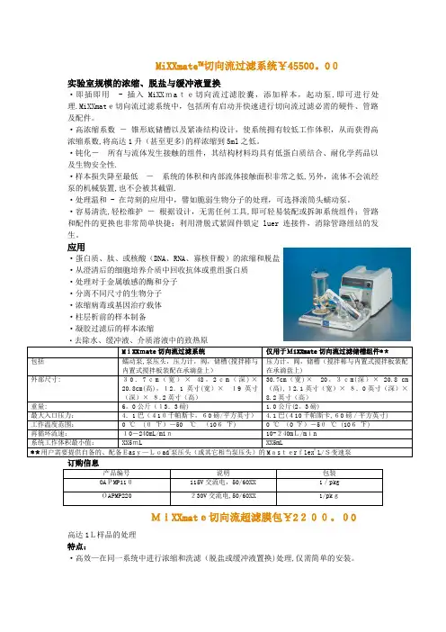
MiXXmate™切向流过滤系统¥45500。
00实验室规模的浓缩、脱盐与缓冲液置换·即插即用- 插入MiXXmate切向流过滤胶囊,添加样本,起动泵,即可进行处理.MiXXmate切向流过滤系统中,包括所有启动并快速进行切向流过滤必需的硬件、管路及配件。
·高浓缩系数-锥形底储槽以及紧凑结构设计,使系统拥有较低工作体积,从而获得高浓缩系数,将高达1升(甚至更多)的样浓缩到5ml之低。
·钝化-所有与流体发生接触的组件,其结构材料均具有低蛋白质结合、耐化学药品以及生物安全性.·样本损失降至最低-系统的体积和内部流体接触面积非常之低,另外,流体不会流经泵的机械装置,也不会被其截留.·处理温和 - 在苛刻的应用中,譬如脆弱生物分子的处理,可选择滚筒头蠕动泵。
·容易清洗,轻松维护-根据设计,无需任何工具,即可轻易装配或拆卸系统组件;管路和配件的更换也非常简单快捷;利用滑脱式紧固件锁定luer连接件,消除管路纽结的发生。
应用·蛋白质、肽、或核酸(DNA、RNA、寡核苷酸)的浓缩和脱盐·从澄清后的细胞培养介质中回收抗体或重组蛋白质·处理对于金属敏感的酶和分子·分离不同尺寸的生物分子·浓缩病毒或基因治疗载体·柱层析前的样本制备·凝胶过滤后的样本浓缩·去除水、缓冲液、介质溶液中的致热原MiXXmate切向流过滤系统仅用于MiXXmate切向流过滤储槽组件**包括蠕动泵,泵压头,压力计,阀,储槽(搅拌棒与内置式搅拌板装配在承滴盘上)压力计,阀,储槽(搅拌棒与内置式搅拌板装配在承滴盘上)外部尺寸: 30.7cm(宽)×48。
2cm(深)×20.8cm(高),12.1英寸(宽)×19英寸(深)×8.2英寸(高)30.7cm(宽)×20。
锅炉补给水处理系统1、自清洗过滤器原理利用钩槽设计叠片,反向相对堆叠,形成可预期的深层式过滤模式.2、技术参数过滤单元规格:3英寸;过滤单元数量:4只/套,共8只;过滤精度:100μm;过滤面积:5968c m2/台;进水水质:经混凝、澄清、过滤后的疏干水和水库水,浊度≤3N T U;出水水质:浊度≤1N T U;最大工作压力:1.0M P a,工作温度:4~60℃;设备额定流量:135m3/h·台,额定流量下运行压差:≤0.1b a r;设备最大流量:160m3/h·台,最大流量下运行压差:≤0.3b a r;反冲洗模式:内源反冲洗(反冲洗时设备不出水,反冲洗进水压力≥0.3M p a;过滤单元材质:玻璃纤维加强聚酰胺;气动三通隔膜阀数量:4只/套,阀体材质:加强聚酰胺,隔膜材质过滤叠片材质:聚丙烯;仪用气源压力:0.4-0.8M P a;品牌:A M I A D;产地:以色列。
2超滤系统膜过滤精度分类超滤膜的过滤原理超滤是一种流体在膜表面的切向流动,其利用较低的压力驱动并按溶质的分子量大小来分离和过滤,是一种物理分离过程。
超滤膜的孔径大约在0.002至0.1微米范围内,主要去除:微粒、胶体、细菌、热源和各种大分子有机物,小分子有机物和无机物几乎不能截留。
超滤膜可通过定期反洗和化学清洗,保证长期使用。
超滤膜过滤形式内压式外压式超滤膜的材料聚砜(P S)聚醚砜(P E S)磺化聚醚砜(S P E S)聚偏氟乙烯(P V D F)聚丙烯腈(P A N)聚氯乙烯(P V C)聚丙烯(P P)超滤的系统组成超滤膜组件,反洗装置,产品水箱,清洗装置.超滤反洗在反洗过程中,反洗水(来自超滤水箱)被反洗泵加压从超滤产水口到浓缩液口“反向”通过系统,从而去除了滤膜浓缩液侧的污垢;在反洗水中投加氯或过氧化物可提高清洗效果。
每0.5小时反洗及快冲1次,每次全过程需用时3分钟(其中反冲洗为1分钟,快冲用时为0.5分钟)。
ROCHEM公司介绍The ROCHEM Group has a worldwide presence with manufacturing and distribution assets strategically located in the major geographical markets of Europe, Asia and America. Through these resources, ROCHEM Group designs and manufactures proprietary and patented membrane-based equipment at the highest of quality standards. Their sales and service network provides a broad presence throughout the globe to ensure successful distribution and after sales support. The ROCHEM group of companies was founded in 1973. Its vision was to serve the needs of marine customers in the marine chemical and maintenance field in all major ports worldwide. ROCHEM eventually established offices in 55 countries – initially for marine clients then for industrial applications.ROCHEM集团拥有一个世界范围内的生产和销售团队,主要是欧洲、亚洲和美国海外市场。
通过这些资源, ROCHEM集团的设计、制造、专利机械设备可以达到最高的质量标准。