FT41-Tutorial1-letter-Chinese - 副本
- 格式:pdf
- 大小:1.02 MB
- 文档页数:13
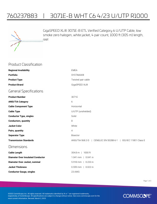
GigaSPEED XL® 3071E-B ETL Verified Category 6 U/UTP Cable, lowsmoke zero halogen, white jacket, 4 pair count, 1000 ft (305 m) length,reelProduct ClassificationRegional Availability EMEAPortfolio SYSTIMAX®Product Type Twisted pair cableProduct Brand GigaSPEED XL®General SpecificationsProduct Number3071EANSI/TIA Category6Cable Component Type HorizontalCable Type U/UTP (unshielded)Conductor Type, singles SolidConductors, quantity8Jacket Color WhitePairs, quantity4Separator Type BisectorTransmission Standards ANSI/TIA-568.2-D | CENELEC EN 50288-6-1 | ISO/IEC 11801 Class E DimensionsCable Length304.8 m | 1000 ftDiameter Over Insulated Conductor 1.041 mm | 0.041 inDiameter Over Jacket, nominal 5.918 mm | 0.233 inJacket Thickness0.559 mm | 0.022 inConductor Gauge, singles23 AWG13Page ofCross Section DrawingElectrical Specificationsdc Resistance Unbalance, maximum 5 %dc Resistance, maximum7.61 ohms/100 m | 2.32 ohms/100 ftDielectric Strength, minimum2500 VdcMutual Capacitance at Frequency 5.6 nF/100 m @ 1 kHzNominal Velocity of Propagation (NVP)70 %Operating Frequency, maximum300 MHzOperating Voltage, maximum80 VRemote Powering Fully complies with the recommendations set forth by IEEE 802.3bt (Type4) for the safe delivery of power over LAN cable when installed accordingto ISO/IEC 14763-2, CENELEC EN 50174-1, CENELEC EN 50174-2 or TIATSB-184-ASegregation Class cMaterial SpecificationsConductor Material Bare copperInsulation Material PolyolefinJacket Material Low Smoke Zero Halogen (LSZH)Separator Material PolyolefinPage of23Mechanical SpecificationsPulling Tension, maximum11.34 kg | 25 lbEnvironmental SpecificationsInstallation temperature0 °C to +60 °C (+32 °F to +140 °F)Operating Temperature-20 °C to +60 °C (-4 °F to +140 °F)Acid Gas Test Method EN 50267-2-3EN50575 CPR Cable EuroClass Fire Performance B2caEN50575 CPR Cable EuroClass Smoke Rating s1aEN50575 CPR Cable EuroClass Droplets Rating d0EN50575 CPR Cable EuroClass Acidity Rating a1Environmental Space Low Smoke Zero Halogen (LSZH)Smoke Test Method IEC 61034-2Packaging and WeightsCable weight38.097 kg/km | 25.6 lb/kftPackaging Type ReelRegulatory Compliance/CertificationsAgency ClassificationCENELEC EN 50575 compliant, Declaration of Performance (DoP) availableCHINA-ROHS Below maximum concentration valueISO 9001:2015Designed, manufactured and/or distributed under this quality management system REACH-SVHC Compliant as per SVHC revision on /ProductCompliance ROHSCompliantPage of33。

9410 - 20 Ave N.W.Edmonton, Alberta, Canada T6N 0A4Tel: (780) 437-9100 / Fax: (780) 437-7787June 10, 2021SERIES FFTM3/FFTM3C VALVESTORONTO, ON M9W 6N9345 CARLINGVIEW DRIVE CRN :Drawing No. :Accepted on:0C23177.52Reg Type:NEW DESIGNApril 13, 2031June 10, 2021Design registered in the name of : A-T CONTROLS INCExpiry Date:SCOPE OF REGISTRATION Fitting type:Attention:The design submission, tracking number 2021-02872, originally received on May 26, 2021 was surveyed and accepted for registration as follows:Sincerely,DICK, ASHLING, P. Eng.TECHNICAL STANDARDS & SAFETY AUTHORITY Tanya FrancisIf you have any question don't hesitate to contact me by phone at (780) 433-0281 ext 3337 or fax (780)****************************.The registration is conditional on your compliance with the following notes:** This registration covers only those valves that are in strict compliance with ASME B16.34, with respect to dimensions, pressure and temperature ratings, materials, markings etc ** See attached Scope of Registration, and a List of Plant SitesAs indicated on AB-41 Statutory Declaration form and submitted documentation, the code of construction is B16.34.- It is our understanding that the fitting(s), included as the scope of this submission, that is(are) subject to the Safety Codes Act shall comply with the requirements of the indicated Standard or Code of Construction on the AB-41 Statutory Declaration as supported by the attached data which identifies the dimensions, materials of construction, press./temp. ratings and the basis for such ratings, and the identification marking of the fittings.- This registration is valid only for fittings fabricated at the location(s) covered by the QC certificate attached to the accepted AB-41 Statutory Declaration form.- This registration is valid only until the indicated expiry date and only if the Manufacturer maintains a valid quality management system approved by an acceptable third-party agency until that date.- Should the approval of the quality management system lapse before the expiry date indicated above, this registration shall become void.DOP Cert. No. D0*******An invoice covering survey and registration fees will be forwarded from our Revenue Accounts.Page 1 of 12021-02872**** Ball Valves Series FFTM3/FFTM3C Class 150, 300 & 600** See attached Scope of Registration and List of Plant SitesABSASAFETY CODES ACT - PROVINCE OF ALBERTASee acceptance letter for conditions of registration.ASHLING DICK, P . Eng.2021-06-10Date:By:This stamp and signature have been affixed electronically to this registered design as required by Section 20(1) of the Pressure Equipment Safety Regulation, in accordance with the Electronic Transactions Act.2021-02872ACCEPTED:0C23177.520C23177.5Technical Standards and Safety Authority Boilers and Pressure Vessels SafetyProgramTHIS IS PART OF CRNABSASAFETY CODES ACT - PROVINCE OF ALBERTASee acceptance letter for conditions of registration.ASHLING DICK, P . Eng.2021-06-10Date:By:This stamp and signature have been affixed electronically to this registered design as required by Section 20(1) of the Pressure Equipment Safety Regulation, in accordance with the Electronic Transactions Act.2021-02872ACCEPTED:0C23177.520C23177.5Technical Standards and Safety Authority Boilers and Pressure Vessels SafetyProgramTHIS IS PART OF CRNBody Materials: ASTM A216 WCB & A351 CF8MABSASAFETY CODES ACT - PROVINCE OF ALBERTASee acceptance letter for conditions of registration.ASHLING DICK, P . Eng.2021-06-10Date:By:This stamp and signature have been affixed electronically to this registered design as required by Section 20(1) of the Pressure Equipment Safety Regulation, in accordance with the Electronic Transactions Act.2021-02872ACCEPTED:0C23177.520C23177.5Technical Standards and Safety Authority Boilers and Pressure Vessels SafetyProgramTHIS IS PART OF CRNABSASAFETY CODES ACT - PROVINCE OF ALBERTASee acceptance letter for conditions of registration.ASHLING DICK, P . Eng.2021-06-10Date:By:This stamp and signature have been affixed electronically to this registered design as required by Section 20(1) of the Pressure Equipment Safety Regulation, in accordance with the Electronic Transactions Act.2021-02872ACCEPTED:0C23177.52April 13, 2021A-T CONTROLS INC9955 INTERNATIONAL BLVDCINCINNATI OH 45246USWorkorder Type: Registration - Fitting(Conventional)Workorder No: 8005180Your Reference No.:Registered to: A-T CONTROLS INCDear PETE VEZEY,Technical Standards and Safety Authority (TSSA) is pleased to inform you that your submission has been reviewed and registered as follows:CRN : 0C23177.5Main Design No.: Ball Valves Series FFTM3/FFTM3C Class 150, 300 & 600 - See Scope of Registration & List of Plant SitesExpiry Date: Apr 13, 2031Please be advised that a valid quality control system must be maintained for the fitting registration to remain valid until the expiry date.The stamped copy of the approved registration and the invoice are mailed separately (There will be no hard copies for electronic submissions). Should you have any questions or require further assistance, please contact a CustomerServiceAdvisorat1.877.682.TSSA(8772)*********************************.Wewillbehappyto assist you. When contacting TSSA regarding this file, please refer to the Service Request number provided above.Yours truly,Wendy DuEngineer, BPVTel. : +1 416-734-3566Email:************Date:C.R.N.:April 13, 2021.0C23177.5Technical Standards and Safety AuthorityBoilers andPressure Vessels Safety ProgramREGISTEREDSigned:- See stamped Scope of Registration & List of Plant SitesApril 13, 20310C23177.5Technical Standards and Safety Authority Boilers and Pressure Vessels SafetyProgramTHIS IS PART OF CRNBody Materials: ASTM A216 WCB & A351 CF8MTHIS IS PART OF CRN 0C23177.5Technical Standards and Safety Authority Boilers and Pressure Vessels SafetyProgramDate:Account #:Journal #:35231June 18, 202178138TECHNICAL STANDARDS & SAFETY AUTHORITY 345 CARLINGVIEW DRIVE TORONTO ON M9W 6N9TSSAApplication for Design RegistrationThe design, as detailed in your, 0C23177.5 - A-T CONTROLS INC, for a Fitting is accepted for registration as follows:A-T CONTROLS, INC.CRN:0C23177.51Registered To:Drawing #:Scope of Registration Drawing Revision:N/ARe:Attn:Reviewer's Notes:Scope of Registration: Ball Valves Series FFTM3/FFTM3C Class 150, 300 & 600 - See Scope of Registration &List of Plant SitesAs required by CSA B51 4.2.1, this registration expires on 13-Apr-2031. This CRN is valid until the expiry date as long as the Manufacturer maintains a valid quality control program verified by an acceptable third-party agency until that date. Should the certification of the quality control program lapse before the expiry date, this registration shall become void. Any additional conditions of registration stated in TSSA CRN# 0C23177.5 registration shall apply to BC registration.This design was registered based on a technical review performed by the province of initial registration in accordance with the Association of Chief Inspectors policy on reciprocal recognition of design review.Contact me if you have any questions. The invoice for registration will be forwarded under separate :Emilia Tam*******************************Design AdministrationInspection and Technical ServicesMunicipal Relations508-401York AveWinnipeg, Manitoba Canada R3C 0P8T 204-945-3373 F 204-948-2089.mb.ca/itsm_main14 June 2021TSSA345 Carlingview DriveToronto, ON M9W 6N9Dear Tanya FrancisRe: Reciprocal CRN Registration in ManitobaYour application indicates that a CRN has been received in another Canadian Jurisdiction, and therefore your CRN has been registered in Manitoba as follows:File Number: 74-R1571CRN: 0C23177.54Scope: SOR: Ball Valve Series FFTM3 / FFTM3C Class 150, 300 & 600 and List of Plant Sites Manufacturer: A-T Controls IncExpiry Date: 13 April 2031Please find attached invoice for registration.As indicated by the Regulatory Reconciliation and Cooperation Table and the Reconciliation Agreement for the Canadian Registration Number (CRN) for Pressure Equipment, a CRN issued in any Canadian Jurisdiction will be accepted for use in Manitoba.In accordance with Steam and Pressure Plants Regulation and CSA B51, it is the manufacturer’s responsibility to file a Manufacturers Data Report, including partial data reports, with our office, prior to shipping pressure equipment to Manitoba.Please contact ****************.ca for any questions or concerns.Inspection and Technical ServicesMunicipal Relations508 - 401 York Avenue, Winnipeg Manitoba R3C 0P8T (204) 945-3373 | F (204) 948-2089。

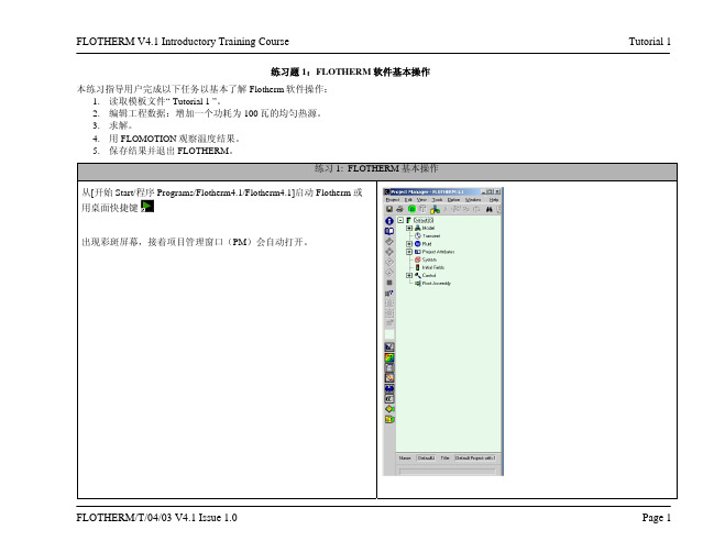
練習題1:FLOTHERM軟體基本操作本練習指導用戶完成以下任務以基本瞭解Flotherm軟體操作:
1.讀取範本檔“ Tutorial 1 ”。
2.編輯工程資料:增加一個功耗為100瓦的均勻熱源。
3.求解。
4.用FLOMOTION觀察溫度結果。
5.保存結果並退出FLOTHERM。
,滾動項目標籤才可得到‘
)圖示
此幾何模型包括一個含有3個通風孔的機箱.如在專案管理器中所示,這些通風孔由一些打孔的板覆蓋。
監控點置於箱子中心,它作為數字熱電偶跟蹤求解過程中的溫度變化(或任何其他變數),要獲取某特定位置上指定的物理量,這是更簡便的方法。
切換到操作模式 (
後,執行以下操作:
可打開調色板並實現對它的開
要創建幾何體,需要點擊圖示將其切換至選擇模式(將‘手’轉
(或使用熱鍵
視圖模式圖示
: Snap to Grid : Snap to Object: Free Snap 從繪圖板中的調色板中選擇幾何體。
這時滑鼠指標將變為十字
備註:您無需以科學計數法的形式輸入各項的值。
您還可以通過使用
此幾何體不是固體,而是可透過空氣的物體。
在這一模型中,我
100W的熱量直接擴散到指定的空間。
中選中這個幾何體,點擊圖示
備註:若在單擊圖示前選中多個物體,則在對話方塊中將顯示所有
現在開始計算。
點擊求解圖示
觀看結果,單擊視覺化圖示
中單擊建立視覺化平面圖標
:
將指標由圖示
變為圖示
或使用熱鍵
(選擇模式)。
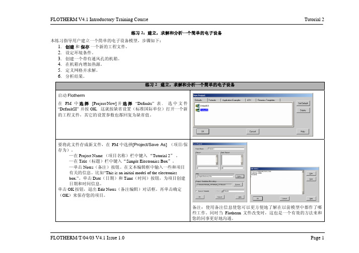
备注:使用备注信息使您可以更方便地了解在以前模型中都作了哪些工作。
同时当Flotherm文件改变时,这也是一个有效的方法来和您的同事更好地沟通。
在此,我们将求解域尺寸设置为与机箱一样大小。
在练习5 中我们将考虑另一种情况。
(或按热键。
要使空气能够在机箱内流通,需要在机箱壁上打孔,以下我们用打
,您将看到三个方向
对话框。
输入以下位置及尺寸
,它。
点击绘图板中的调色板
“Low Y
,回到四视图状态。
选中视图‘Low Z’上依同样方法画出一个
机箱壁面上,所以我们要把它。
注意:从项目管理器中选择这
拖到左面的机箱
High Z Plate Low Z Plate 壁。
注意:一定要点中所选部件的边缘处再移动部件,否则会改变
切换至四视图模式。
将
“25
并点击调色板中的监控点图标
备注:要保证创建的监控点位于机箱的中心,只有通过PM才能实
现。
创建两个子组件。
将它们分别命
点击图标进入
定义中等网格。
软件会根据模型的情况自动设置最小
已选中,这样,网格就可以自动更新。
检查绘。
中单击建立可视化平面图标
键将实体转变为线框模型。
点击图标
及鼠标左键旋转视图。
通过滚动区域进行缩放。
Variable displayed
Plane
Manipulator。

The information in this document is subject to change without notice and does not represent a commitment on the part of Native Instruments GmbH. The software described by this docu-ment is subject to a License Agreement and may not be copied to other media. No part of this publication may be copied, reproduced or otherwise transmitted or recorded, for any purpose, without prior written permission by Native Instruments GmbH, hereinafter referred to as Native Instruments.“Native Instruments”, “NI” and associated logos are (registered) trademarks of Native Instru-ments GmbH.ASIO, VST, HALion and Cubase are registered trademarks of Steinberg Media Technologies GmbH.All other product and company names are trademarks™ or registered® trademarks of their re-spective holders. Use of them does not imply any affiliation with or endorsement by them.Document authored by: David Gover and Nico Sidi.Software version: 2.8 (02/2019)Hardware version: MASCHINE MIKRO MK3Special thanks to the Beta Test Team, who were invaluable not just in tracking down bugs, but in making this a better product.NATIVE INSTRUMENTS GmbH Schlesische Str. 29-30D-10997 Berlin Germanywww.native-instruments.de NATIVE INSTRUMENTS North America, Inc. 6725 Sunset Boulevard5th FloorLos Angeles, CA 90028USANATIVE INSTRUMENTS K.K.YO Building 3FJingumae 6-7-15, Shibuya-ku, Tokyo 150-0001Japanwww.native-instruments.co.jp NATIVE INSTRUMENTS UK Limited 18 Phipp StreetLondon EC2A 4NUUKNATIVE INSTRUMENTS FRANCE SARL 113 Rue Saint-Maur75011 ParisFrance SHENZHEN NATIVE INSTRUMENTS COMPANY Limited 5F, Shenzhen Zimao Center111 Taizi Road, Nanshan District, Shenzhen, GuangdongChina© NATIVE INSTRUMENTS GmbH, 2019. All rights reserved.Table of Contents1Welcome to MASCHINE (23)1.1MASCHINE Documentation (24)1.2Document Conventions (25)1.3New Features in MASCHINE 2.8 (26)1.4New Features in MASCHINE 2.7.10 (28)1.5New Features in MASCHINE 2.7.8 (29)1.6New Features in MASCHINE 2.7.7 (29)1.7New Features in MASCHINE 2.7.4 (31)1.8New Features in MASCHINE 2.7.3 (33)2Quick Reference (35)2.1MASCHINE Project Overview (35)2.1.1Sound Content (35)2.1.2Arrangement (37)2.2MASCHINE Hardware Overview (40)2.2.1MASCHINE MIKRO Hardware Overview (40)2.2.1.1Browser Section (41)2.2.1.2Edit Section (42)2.2.1.3Performance Section (43)2.2.1.4Transport Section (45)2.2.1.5Pad Section (46)2.2.1.6Rear Panel (50)2.3MASCHINE Software Overview (51)2.3.1Header (52)2.3.2Browser (54)2.3.3Arranger (56)2.3.4Control Area (59)2.3.5Pattern Editor (60)3Basic Concepts (62)3.1Important Names and Concepts (62)3.2Adjusting the MASCHINE User Interface (65)3.2.1Adjusting the Size of the Interface (65)3.2.2Switching between Ideas View and Song View (66)3.2.3Showing/Hiding the Browser (67)3.2.4Showing/Hiding the Control Lane (67)3.3Common Operations (68)3.3.1Adjusting Volume, Swing, and Tempo (68)3.3.2Undo/Redo (71)3.3.3Focusing on a Group or a Sound (73)3.3.4Switching Between the Master, Group, and Sound Level (77)3.3.5Navigating Channel Properties, Plug-ins, and Parameter Pages in the Control Area.773.3.6Navigating the Software Using the Controller (82)3.3.7Using Two or More Hardware Controllers (82)3.3.8Loading a Recent Project from the Controller (84)3.4Native Kontrol Standard (85)3.5Stand-Alone and Plug-in Mode (86)3.5.1Differences between Stand-Alone and Plug-in Mode (86)3.5.2Switching Instances (88)3.6Preferences (88)3.6.1Preferences – General Page (89)3.6.2Preferences – Audio Page (93)3.6.3Preferences – MIDI Page (95)3.6.4Preferences – Default Page (97)3.6.5Preferences – Library Page (101)3.6.6Preferences – Plug-ins Page (109)3.6.7Preferences – Hardware Page (114)3.6.8Preferences – Colors Page (114)3.7Integrating MASCHINE into a MIDI Setup (117)3.7.1Connecting External MIDI Equipment (117)3.7.2Sync to External MIDI Clock (117)3.7.3Send MIDI Clock (118)3.7.4Using MIDI Mode (119)3.8Syncing MASCHINE using Ableton Link (120)3.8.1Connecting to a Network (121)3.8.2Joining and Leaving a Link Session (121)4Browser (123)4.1Browser Basics (123)4.1.1The MASCHINE Library (123)4.1.2Browsing the Library vs. Browsing Your Hard Disks (124)4.2Searching and Loading Files from the Library (125)4.2.1Overview of the Library Pane (125)4.2.2Selecting or Loading a Product and Selecting a Bank from the Browser (128)4.2.3Selecting a Product Category, a Product, a Bank, and a Sub-Bank (133)4.2.3.1Selecting a Product Category, a Product, a Bank, and a Sub-Bank on theController (137)4.2.4Selecting a File Type (137)4.2.5Choosing Between Factory and User Content (138)4.2.6Selecting Type and Character Tags (138)4.2.7Performing a Text Search (142)4.2.8Loading a File from the Result List (143)4.3Additional Browsing Tools (148)4.3.1Loading the Selected Files Automatically (148)4.3.2Auditioning Instrument Presets (149)4.3.3Auditioning Samples (150)4.3.4Loading Groups with Patterns (150)4.3.5Loading Groups with Routing (151)4.3.6Displaying File Information (151)4.4Using Favorites in the Browser (152)4.5Editing the Files’ Tags and Properties (155)4.5.1Attribute Editor Basics (155)4.5.2The Bank Page (157)4.5.3The Types and Characters Pages (157)4.5.4The Properties Page (160)4.6Loading and Importing Files from Your File System (161)4.6.1Overview of the FILES Pane (161)4.6.2Using Favorites (163)4.6.3Using the Location Bar (164)4.6.4Navigating to Recent Locations (165)4.6.5Using the Result List (166)4.6.6Importing Files to the MASCHINE Library (169)4.7Locating Missing Samples (171)4.8Using Quick Browse (173)5Managing Sounds, Groups, and Your Project (175)5.1Overview of the Sounds, Groups, and Master (175)5.1.1The Sound, Group, and Master Channels (176)5.1.2Similarities and Differences in Handling Sounds and Groups (177)5.1.3Selecting Multiple Sounds or Groups (178)5.2Managing Sounds (181)5.2.1Loading Sounds (183)5.2.2Pre-listening to Sounds (184)5.2.3Renaming Sound Slots (185)5.2.4Changing the Sound’s Color (186)5.2.5Saving Sounds (187)5.2.6Copying and Pasting Sounds (189)5.2.7Moving Sounds (192)5.2.8Resetting Sound Slots (193)5.3Managing Groups (194)5.3.1Creating Groups (196)5.3.2Loading Groups (197)5.3.3Renaming Groups (198)5.3.4Changing the Group’s Color (199)5.3.5Saving Groups (200)5.3.6Copying and Pasting Groups (202)5.3.7Reordering Groups (206)5.3.8Deleting Groups (207)5.4Exporting MASCHINE Objects and Audio (208)5.4.1Saving a Group with its Samples (208)5.4.2Saving a Project with its Samples (210)5.4.3Exporting Audio (212)5.5Importing Third-Party File Formats (218)5.5.1Loading REX Files into Sound Slots (218)5.5.2Importing MPC Programs to Groups (219)6Playing on the Controller (223)6.1Adjusting the Pads (223)6.1.1The Pad View in the Software (223)6.1.2Choosing a Pad Input Mode (225)6.1.3Adjusting the Base Key (226)6.2Adjusting the Key, Choke, and Link Parameters for Multiple Sounds (227)6.3Playing Tools (229)6.3.1Mute and Solo (229)6.3.2Choke All Notes (233)6.3.3Groove (233)6.3.4Level, Tempo, Tune, and Groove Shortcuts on Your Controller (235)6.3.5Tap Tempo (235)6.4Performance Features (236)6.4.1Overview of the Perform Features (236)6.4.2Selecting a Scale and Creating Chords (239)6.4.3Scale and Chord Parameters (240)6.4.4Creating Arpeggios and Repeated Notes (253)6.4.5Swing on Note Repeat / Arp Output (257)6.5Using Lock Snapshots (257)6.5.1Creating a Lock Snapshot (257)7Working with Plug-ins (259)7.1Plug-in Overview (259)7.1.1Plug-in Basics (259)7.1.2First Plug-in Slot of Sounds: Choosing the Sound’s Role (263)7.1.3Loading, Removing, and Replacing a Plug-in (264)7.1.4Adjusting the Plug-in Parameters (270)7.1.5Bypassing Plug-in Slots (270)7.1.6Using Side-Chain (272)7.1.7Moving Plug-ins (272)7.1.8Alternative: the Plug-in Strip (273)7.1.9Saving and Recalling Plug-in Presets (273)7.1.9.1Saving Plug-in Presets (274)7.1.9.2Recalling Plug-in Presets (275)7.1.9.3Removing a Default Plug-in Preset (276)7.2The Sampler Plug-in (277)7.2.1Page 1: Voice Settings / Engine (279)7.2.2Page 2: Pitch / Envelope (281)7.2.3Page 3: FX / Filter (283)7.2.4Page 4: Modulation (285)7.2.5Page 5: LFO (286)7.2.6Page 6: Velocity / Modwheel (288)7.3Using Native Instruments and External Plug-ins (289)7.3.1Opening/Closing Plug-in Windows (289)7.3.2Using the VST/AU Plug-in Parameters (292)7.3.3Setting Up Your Own Parameter Pages (293)7.3.4Using VST/AU Plug-in Presets (298)7.3.5Multiple-Output Plug-ins and Multitimbral Plug-ins (300)8Using the Audio Plug-in (302)8.1Loading a Loop into the Audio Plug-in (306)8.2Editing Audio in the Audio Plug-in (307)8.3Using Loop Mode (308)8.4Using Gate Mode (310)9Using the Drumsynths (312)9.1Drumsynths – General Handling (313)9.1.1Engines: Many Different Drums per Drumsynth (313)9.1.2Common Parameter Organization (313)9.1.3Shared Parameters (316)9.1.4Various Velocity Responses (316)9.1.5Pitch Range, Tuning, and MIDI Notes (316)9.2The Kicks (317)9.2.1Kick – Sub (319)9.2.2Kick – Tronic (321)9.2.3Kick – Dusty (324)9.2.4Kick – Grit (325)9.2.5Kick – Rasper (328)9.2.6Kick – Snappy (329)9.2.7Kick – Bold (331)9.2.8Kick – Maple (333)9.2.9Kick – Push (334)9.3The Snares (336)9.3.1Snare – Volt (338)9.3.2Snare – Bit (340)9.3.3Snare – Pow (342)9.3.4Snare – Sharp (343)9.3.5Snare – Airy (345)9.3.6Snare – Vintage (347)9.3.7Snare – Chrome (349)9.3.8Snare – Iron (351)9.3.9Snare – Clap (353)9.3.10Snare – Breaker (355)9.4The Hi-hats (357)9.4.1Hi-hat – Silver (358)9.4.2Hi-hat – Circuit (360)9.4.3Hi-hat – Memory (362)9.4.4Hi-hat – Hybrid (364)9.4.5Creating a Pattern with Closed and Open Hi-hats (366)9.5The Toms (367)9.5.1Tom – Tronic (369)9.5.2Tom – Fractal (371)9.5.3Tom – Floor (375)9.5.4Tom – High (377)9.6The Percussions (378)9.6.1Percussion – Fractal (380)9.6.2Percussion – Kettle (383)9.6.3Percussion – Shaker (385)9.7The Cymbals (389)9.7.1Cymbal – Crash (391)9.7.2Cymbal – Ride (393)10Using the Bass Synth (396)10.1Bass Synth – General Handling (397)10.1.1Parameter Organization (397)10.1.2Bass Synth Parameters (399)11Working with Patterns (401)11.1Pattern Basics (401)11.1.1Pattern Editor Overview (402)11.1.2Navigating the Event Area (404)11.1.3Following the Playback Position in the Pattern (406)11.1.4Jumping to Another Playback Position in the Pattern (407)11.1.5Group View and Keyboard View (408)11.1.6Adjusting the Arrange Grid and the Pattern Length (410)11.1.7Adjusting the Step Grid and the Nudge Grid (413)11.2Recording Patterns in Real Time (416)11.2.1Recording Your Patterns Live (417)11.2.2Using the Metronome (419)11.2.3Recording with Count-in (420)11.3Recording Patterns with the Step Sequencer (422)11.3.1Step Mode Basics (422)11.3.2Editing Events in Step Mode (424)11.4Editing Events (425)11.4.1Editing Events with the Mouse: an Overview (425)11.4.2Creating Events/Notes (428)11.4.3Selecting Events/Notes (429)11.4.4Editing Selected Events/Notes (431)11.4.5Deleting Events/Notes (434)11.4.6Cut, Copy, and Paste Events/Notes (436)11.4.7Quantizing Events/Notes (439)11.4.8Quantization While Playing (441)11.4.9Doubling a Pattern (442)11.4.10Adding Variation to Patterns (442)11.5Recording and Editing Modulation (443)11.5.1Which Parameters Are Modulatable? (444)11.5.2Recording Modulation (446)11.5.3Creating and Editing Modulation in the Control Lane (447)11.6Creating MIDI Tracks from Scratch in MASCHINE (452)11.7Managing Patterns (454)11.7.1The Pattern Manager and Pattern Mode (455)11.7.2Selecting Patterns and Pattern Banks (456)11.7.3Creating Patterns (459)11.7.4Deleting Patterns (460)11.7.5Creating and Deleting Pattern Banks (461)11.7.6Naming Patterns (463)11.7.7Changing the Pattern’s Color (465)11.7.8Duplicating, Copying, and Pasting Patterns (466)11.7.9Moving Patterns (469)11.8Importing/Exporting Audio and MIDI to/from Patterns (470)11.8.1Exporting Audio from Patterns (470)11.8.2Exporting MIDI from Patterns (472)11.8.3Importing MIDI to Patterns (474)12Audio Routing, Remote Control, and Macro Controls (483)12.1Audio Routing in MASCHINE (484)12.1.1Sending External Audio to Sounds (485)12.1.2Configuring the Main Output of Sounds and Groups (489)12.1.3Setting Up Auxiliary Outputs for Sounds and Groups (494)12.1.4Configuring the Master and Cue Outputs of MASCHINE (497)12.1.5Mono Audio Inputs (502)12.1.5.1Configuring External Inputs for Sounds in Mix View (503)12.2Using MIDI Control and Host Automation (506)12.2.1Triggering Sounds via MIDI Notes (507)12.2.2Triggering Scenes via MIDI (513)12.2.3Controlling Parameters via MIDI and Host Automation (514)12.2.4Selecting VST/AU Plug-in Presets via MIDI Program Change (522)12.2.5Sending MIDI from Sounds (523)12.3Creating Custom Sets of Parameters with the Macro Controls (527)12.3.1Macro Control Overview (527)12.3.2Assigning Macro Controls Using the Software (528)13Controlling Your Mix (535)13.1Mix View Basics (535)13.1.1Switching between Arrange View and Mix View (535)13.1.2Mix View Elements (536)13.2The Mixer (537)13.2.1Displaying Groups vs. Displaying Sounds (539)13.2.2Adjusting the Mixer Layout (541)13.2.3Selecting Channel Strips (542)13.2.4Managing Your Channels in the Mixer (543)13.2.5Adjusting Settings in the Channel Strips (545)13.2.6Using the Cue Bus (549)13.3The Plug-in Chain (551)13.4The Plug-in Strip (552)13.4.1The Plug-in Header (554)13.4.2Panels for Drumsynths and Internal Effects (556)13.4.3Panel for the Sampler (557)13.4.4Custom Panels for Native Instruments Plug-ins (560)13.4.5Undocking a Plug-in Panel (Native Instruments and External Plug-ins Only) (564)14Using Effects (567)14.1Applying Effects to a Sound, a Group or the Master (567)14.1.1Adding an Effect (567)14.1.2Other Operations on Effects (574)14.1.3Using the Side-Chain Input (575)14.2Applying Effects to External Audio (578)14.2.1Step 1: Configure MASCHINE Audio Inputs (578)14.2.2Step 2: Set up a Sound to Receive the External Input (579)14.2.3Step 3: Load an Effect to Process an Input (579)14.3Creating a Send Effect (580)14.3.1Step 1: Set Up a Sound or Group as Send Effect (581)14.3.2Step 2: Route Audio to the Send Effect (583)14.3.3 A Few Notes on Send Effects (583)14.4Creating Multi-Effects (584)15Effect Reference (587)15.1Dynamics (588)15.1.1Compressor (588)15.1.2Gate (591)15.1.3Transient Master (594)15.1.4Limiter (596)15.1.5Maximizer (600)15.2Filtering Effects (603)15.2.1EQ (603)15.2.2Filter (605)15.2.3Cabinet (609)15.3Modulation Effects (611)15.3.1Chorus (611)15.3.2Flanger (612)15.3.3FM (613)15.3.4Freq Shifter (615)15.3.5Phaser (616)15.4Spatial and Reverb Effects (617)15.4.1Ice (617)15.4.2Metaverb (619)15.4.3Reflex (620)15.4.4Reverb (Legacy) (621)15.4.5Reverb (623)15.4.5.1Reverb Room (623)15.4.5.2Reverb Hall (626)15.4.5.3Plate Reverb (629)15.5Delays (630)15.5.1Beat Delay (630)15.5.2Grain Delay (632)15.5.3Grain Stretch (634)15.5.4Resochord (636)15.6Distortion Effects (638)15.6.1Distortion (638)15.6.2Lofi (640)15.6.3Saturator (641)15.7Perform FX (645)15.7.1Filter (646)15.7.2Flanger (648)15.7.3Burst Echo (650)15.7.4Reso Echo (653)15.7.5Ring (656)15.7.6Stutter (658)15.7.7Tremolo (661)15.7.8Scratcher (664)16Working with the Arranger (667)16.1Arranger Basics (667)16.1.1Navigating Song View (670)16.1.2Following the Playback Position in Your Project (672)16.1.3Performing with Scenes and Sections using the Pads (673)16.2Using Ideas View (677)16.2.1Scene Overview (677)16.2.2Creating Scenes (679)16.2.3Assigning and Removing Patterns (679)16.2.4Selecting Scenes (682)16.2.5Deleting Scenes (684)16.2.6Creating and Deleting Scene Banks (685)16.2.7Clearing Scenes (685)16.2.8Duplicating Scenes (685)16.2.9Reordering Scenes (687)16.2.10Making Scenes Unique (688)16.2.11Appending Scenes to Arrangement (689)16.2.12Naming Scenes (689)16.2.13Changing the Color of a Scene (690)16.3Using Song View (692)16.3.1Section Management Overview (692)16.3.2Creating Sections (694)16.3.3Assigning a Scene to a Section (695)16.3.4Selecting Sections and Section Banks (696)16.3.5Reorganizing Sections (700)16.3.6Adjusting the Length of a Section (702)16.3.6.1Adjusting the Length of a Section Using the Software (703)16.3.6.2Adjusting the Length of a Section Using the Controller (705)16.3.7Clearing a Pattern in Song View (705)16.3.8Duplicating Sections (705)16.3.8.1Making Sections Unique (707)16.3.9Removing Sections (707)16.3.10Renaming Scenes (708)16.3.11Clearing Sections (710)16.3.12Creating and Deleting Section Banks (710)16.3.13Working with Patterns in Song view (710)16.3.13.1Creating a Pattern in Song View (711)16.3.13.2Selecting a Pattern in Song View (711)16.3.13.3Clearing a Pattern in Song View (711)16.3.13.4Renaming a Pattern in Song View (711)16.3.13.5Coloring a Pattern in Song View (712)16.3.13.6Removing a Pattern in Song View (712)16.3.13.7Duplicating a Pattern in Song View (712)16.3.14Enabling Auto Length (713)16.3.15Looping (714)16.3.15.1Setting the Loop Range in the Software (714)16.3.15.2Activating or Deactivating a Loop Using the Controller (715)16.4Playing with Sections (715)16.4.1Jumping to another Playback Position in Your Project (716)16.5Triggering Sections or Scenes via MIDI (717)16.6The Arrange Grid (719)16.7Quick Grid (720)17Sampling and Sample Mapping (722)17.1Opening the Sample Editor (722)17.2Recording Audio (724)17.2.1Opening the Record Page (724)17.2.2Selecting the Source and the Recording Mode (725)17.2.3Arming, Starting, and Stopping the Recording (729)17.2.5Checking Your Recordings (731)17.2.6Location and Name of Your Recorded Samples (734)17.3Editing a Sample (735)17.3.1Using the Edit Page (735)17.3.2Audio Editing Functions (739)17.4Slicing a Sample (743)17.4.1Opening the Slice Page (743)17.4.2Adjusting the Slicing Settings (744)17.4.3Manually Adjusting Your Slices (746)17.4.4Applying the Slicing (750)17.5Mapping Samples to Zones (754)17.5.1Opening the Zone Page (754)17.5.2Zone Page Overview (755)17.5.3Selecting and Managing Zones in the Zone List (756)17.5.4Selecting and Editing Zones in the Map View (761)17.5.5Editing Zones in the Sample View (765)17.5.6Adjusting the Zone Settings (767)17.5.7Adding Samples to the Sample Map (770)18Appendix: Tips for Playing Live (772)18.1Preparations (772)18.1.1Focus on the Hardware (772)18.1.2Customize the Pads of the Hardware (772)18.1.3Check Your CPU Power Before Playing (772)18.1.4Name and Color Your Groups, Patterns, Sounds and Scenes (773)18.1.5Consider Using a Limiter on Your Master (773)18.1.6Hook Up Your Other Gear and Sync It with MIDI Clock (773)18.1.7Improvise (773)18.2Basic Techniques (773)18.2.1Use Mute and Solo (773)18.2.2Create Variations of Your Drum Patterns in the Step Sequencer (774)18.2.3Use Note Repeat (774)18.2.4Set Up Your Own Multi-effect Groups and Automate Them (774)18.3Special Tricks (774)18.3.1Changing Pattern Length for Variation (774)18.3.2Using Loops to Cycle Through Samples (775)18.3.3Load Long Audio Files and Play with the Start Point (775)19Troubleshooting (776)19.1Knowledge Base (776)19.2Technical Support (776)19.3Registration Support (777)19.4User Forum (777)20Glossary (778)Index (786)1Welcome to MASCHINEThank you for buying MASCHINE!MASCHINE is a groove production studio that implements the familiar working style of classi-cal groove boxes along with the advantages of a computer based system. MASCHINE is ideal for making music live, as well as in the studio. It’s the hands-on aspect of a dedicated instru-ment, the MASCHINE hardware controller, united with the advanced editing features of the MASCHINE software.Creating beats is often not very intuitive with a computer, but using the MASCHINE hardware controller to do it makes it easy and fun. You can tap in freely with the pads or use Note Re-peat to jam along. Alternatively, build your beats using the step sequencer just as in classic drum machines.Patterns can be intuitively combined and rearranged on the fly to form larger ideas. You can try out several different versions of a song without ever having to stop the music.Since you can integrate it into any sequencer that supports VST, AU, or AAX plug-ins, you can reap the benefits in almost any software setup, or use it as a stand-alone application. You can sample your own material, slice loops and rearrange them easily.However, MASCHINE is a lot more than an ordinary groovebox or sampler: it comes with an inspiring 7-gigabyte library, and a sophisticated, yet easy to use tag-based Browser to give you instant access to the sounds you are looking for.What’s more, MASCHINE provides lots of options for manipulating your sounds via internal ef-fects and other sound-shaping possibilities. You can also control external MIDI hardware and 3rd-party software with the MASCHINE hardware controller, while customizing the functions of the pads, knobs and buttons according to your needs utilizing the included Controller Editor application. We hope you enjoy this fantastic instrument as much as we do. Now let’s get go-ing!—The MASCHINE team at Native Instruments.MASCHINE Documentation1.1MASCHINE DocumentationNative Instruments provide many information sources regarding MASCHINE. The main docu-ments should be read in the following sequence:1.MASCHINE MIKRO Quick Start Guide: This animated online guide provides a practical ap-proach to help you learn the basic of MASCHINE MIKRO. The guide is available from theNative Instruments website: https:///maschine-mikro-quick-start/2.MASCHINE Manual (this document): The MASCHINE Manual provides you with a compre-hensive description of all MASCHINE software and hardware features.Additional documentation sources provide you with details on more specific topics:►Online Support Videos: You can find a number of support videos on The Official Native In-struments Support Channel under the following URL: https:///NIsupport-EN. We recommend that you follow along with these instructions while the respective ap-plication is running on your computer.Other Online Resources:If you are experiencing problems related to your Native Instruments product that the supplied documentation does not cover, there are several ways of getting help:▪Knowledge Base▪User Forum▪Technical Support▪Registration SupportYou will find more information on these subjects in the chapter Troubleshooting.Document Conventions1.2Document ConventionsThis section introduces you to the signage and text highlighting used in this manual. This man-ual uses particular formatting to point out special facts and to warn you of potential issues.The icons introducing these notes let you see what kind of information is to be expected:This document uses particular formatting to point out special facts and to warn you of poten-tial issues. The icons introducing the following notes let you see what kind of information canbe expected:Furthermore, the following formatting is used:▪Text appearing in (drop-down) menus (such as Open…, Save as… etc.) in the software andpaths to locations on your hard disk or other storage devices is printed in italics.▪Text appearing elsewhere (labels of buttons, controls, text next to checkboxes etc.) in thesoftware is printed in blue. Whenever you see this formatting applied, you will find thesame text appearing somewhere on the screen.▪Text appearing on the displays of the controller is printed in light grey. Whenever you seethis formatting applied, you will find the same text on a controller display.▪Text appearing on labels of the hardware controller is printed in orange. Whenever you seethis formatting applied, you will find the same text on the controller.▪Important names and concepts are printed in bold.▪References to keys on your computer’s keyboard you’ll find put in square brackets (e.g.,“Press [Shift] + [Enter]”).►Single instructions are introduced by this play button type arrow.→Results of actions are introduced by this smaller arrow.Naming ConventionThroughout the documentation we will refer to MASCHINE controller (or just controller) as the hardware controller and MASCHINE software as the software installed on your computer.The term “effect” will sometimes be abbreviated as “FX” when referring to elements in the MA-SCHINE software and hardware. These terms have the same meaning.Button Combinations and Shortcuts on Your ControllerMost instructions will use the “+” sign to indicate buttons (or buttons and pads) that must be pressed simultaneously, starting with the button indicated first. E.g., an instruction such as:“Press SHIFT + PLAY”means:1.Press and hold SHIFT.2.While holding SHIFT, press PLAY and release it.3.Release SHIFT.1.3New Features in MASCHINE2.8The following new features have been added to MASCHINE: Integration▪Browse on , create your own collections of loops and one-shots and send them directly to the MASCHINE browser.Improvements to the Browser▪Samples are now cataloged in separate Loops and One-shots tabs in the Browser.▪Previews of loops selected in the Browser will be played in sync with the current project.When a loop is selected with Prehear turned on, it will begin playing immediately in-sync with the project if transport is running. If a loop preview starts part-way through the loop, the loop will play once more for its full length to ensure you get to hear the entire loop once in context with your project.▪Filters and product selections will be remembered when switching between content types and Factory/User Libraries in the Browser.▪Browser content synchronization between multiple running instances. When running multi-ple instances of MASCHINE, either as Standalone and/or as a plug-in, updates to the Li-brary will be synced across the instances. For example, if you delete a sample from your User Library in one instance, the sample will no longer be present in the other instances.Similarly, if you save a preset in one instance, that preset will then be available in the oth-er instances, too.▪Edits made to samples in the Factory Libraries will be saved to the Standard User Directo-ry.For more information on these new features, refer to the following chapter ↑4, Browser. Improvements to the MASCHINE MIKRO MK3 Controller▪You can now set sample Start and End points using the controller. For more information refer to ↑17.3.1, Using the Edit Page.Improved Support for A-Series Keyboards▪When Browsing with A-Series keyboards, you can now jump quickly to the results list by holding SHIFT and pushing right on the 4D Encoder.▪When Browsing with A-Series keyboards, you can fast scroll through the Browser results list by holding SHIFT and twisting the 4D Encoder.▪Mute and Solo Sounds and Groups from A-Series keyboards. Sounds are muted in TRACK mode while Groups are muted in IDEAS.。
TutorialsIGG™ v8.aDocumentation v8.aNUMECA International5, Avenue Franklin Roosevelt1050 BrusselsBelgiumTel: +32 2 647.83.11Fax: +32 2 647.93.98Web: ContentsTABLE OF CONTENTINTRODUCTIONTUTORIAL 1: Geometry Creation1-1 INTRODUCTION1-11-1.1 Introduction1-11-1.2 Prerequisites1-21-1.3 Preparation1-21-2 CARTESIAN POINT1-31-2.1 Create Cartesian Point1-31-2.2 Select Cartesian Point1-31-2.3 Delete Cartesian Point1-31-3 CURVES1-31-3.1 Create Curves1-31-3.2 Select Curves1-51-3.3 Visualize Curves1-51-3.4 Modify Curves1-61-3.5 Edit/Copy Curves1-71-3.6 Export Curves1-71-3 SURFACES1-81-3.1 Create Surfaces1-81-3.2 Select Surfaces1-101-3.3 Visualize Surfaces1-101-3.4 Modify Surfaces1-111-3.5 Edit/Copy Surfaces1-111-3.6 Export Surfaces1-11 TUTORIAL 2: 2D Airfoil Mesh Generation2-1 INTRODUCTION2-12-1.1 Introduction2-12-1.2 Prerequisites2-22-1.3 Presentation2-22-1.4 Preparation2-22-2 MESH GENERATION2-32-2.1 Define Project Configuration2-42-2.2 Define Geometry2-52-2.3 Create Blocks2-62-2.4 Define Clustering2-112-2.5 Generate Face Grid2-142-2.6 Control Mesh Quality2-162-2.7 Define Boundary Conditions2-172-2.8 Save Project2-18ContentsTUTORIAL 3: Pipe to Pipe Mesh Generation3-1 INTRODUCTION3-13-1.1 Introduction3-13-1.2 Prerequisites3-23-1.3 Presentation3-23-1.4 Preparation3-23-2 MESH GENERATION3-33-2.1 Define Geometry3-33-2.2 Create & Control Blocks3-53-2.3 Generate Block Grid3-133-2.4 Define Butterfly Topology3-143-2.5 Control Mesh Quality3-163-2.6 Define Boundary Conditions3-183-2.7 Define Full Non Matching Connection3-193-2.8 Save Project3-20TUTORIAL 4: Volute Mesh Generation4-1 INTRODUCTION4-14-1.1 Introduction4-14-1.2 Prerequisites4-24-1.3 Presentation4-24-1.4 Preparation4-24-2 MESH GENERATION4-34-2.1 Load Geometry4-34-2.2 Create & Control Blocks4-44-2.3 Generate Block Grid4-184-2.4 Control Mesh Quality4-194-2.5 Define Boundary Conditions4-204-2.6 Define Full Non Matching Connection4-224-2.7 Save Project4-23TUTORIAL 5: Axi Seal Leakage Mesh Generation5-1 INTRODUCTION5-15-1.1 Introduction5-15-1.2 Prerequisites5-25-1.3 Presentation5-25-1.4 Preparation5-25-2 MESH GENERATION5-35-2.1 Define Project Configuration5-35-2.2 Import Geometry5-45-2.3 Create & Control Blocks5-45-2.4 Define Clustering5-105-2.5 Control Mesh Quality5-135-2.6 Define Boundary Conditions5-155-2.7 Save Project5-18What’s in This Guide ?This Tutorial Guide contains a number of tutorials driving the user in IGG™ v8 to mesh different internal and external configurations. In each tutorial, features related to mesh generation are dem-onstrated.Tutorials 1 to 5 are detailed tutorials designed to introduce the beginner to IGG™ v8. These tutori-als provide explicit instructions for all steps of the mesh generation process. Tutorials 1 to 5 do not require any pre-requisite and can be treated separately, in any order. They address different types of applications, including both internal and external cases.Where to Find the Files Used in the Tutorials ?Each of the mesh generation starts from a geometry that is existing or is created. The appropriate files (and any other relevant files used in the tutorial) are stored on IGG™ v8 DVD-ROM, more precisely in the /DOC/_Tutorials directory.How to Use this Guide ?Depending upon your familiarity with computational fluid dynamics and your interest in some par-ticular configuration, you can use this tutorial guide in a variety of ways.For the BeginnerIf you are beginning user of IGG™, you should first read and solve tutorials 1 and 2, in order to familiarize yourself with the interface and basis of the mesh generation technique. You may then want to concentrate on a tutorial that demonstrates features that you are going to resolve. For exam-ple, if you are planning to mesh a volute, you should look at tutorial 4.For the Experienced UserIf you are an experienced user of IGG™, you can read and/or solve the tutorial(s) that demonstrate features that you are going to resolve. For example, if you plan to mesh a 2D airfoil, you should look at tutorial 2.Conventions Used in this GuideSeveral conventions are used in the tutorials to facilitate your learning process.Following a short introduction, each tutorial is divided into sections respectively related to the mesh generation steps from the geometry definition to the 3D mesh generation.Inputs required to execute the tutorials are restricted to the geometry, either in a ".dat" or CAD related format.The sequence of actions to be executed are described through a step-by-step approach, in the form of arabic numbers.Additional insight about some specific actions and/or features is frequently added to illustrate the tutorial further. This information is proposed for the purpose of clarity and completeness, and should not be executed. It appears in italicized type.Contact NUMECA support team at +32-2-647.83.11 or send an e-mail to sup-port@numeca.be for any question or information you may require. To allowNUMECA support to help you out within the shortest delays, please provide adetailed description of the observed behaviour and performed analysis.TUTORIAL 1:Geometry Creation1-1Introduction1-1.1IntroductionThe resolution of computational fluid dynamics (CFD) problems involves three main steps:•spatial discretization of the flow equations,•flow computation,•visualization of the results.To answer these questions, NUMECA has developed a F low IN tegrated E nvironment for internaland Turbomachinery assimilations. Called FINE™/Turbo, the environment integrates the followingtools:•IGG™ is an I nteractive G eometry modeler and G rid generator software, based on structured multi-block techniques,•AutoGrid™ is a three-dimensional Automated Grid generation software, dedicated to turboma-chinery applications. Similarly to IGG™, it is based on structured multi-block techniques,•Euranus is a state-of-the-art multi-block flow solver, able to simulate Euler and Navier-Stokes equations in the laminar, transitional and turbulent regimes,•CFView™ is a highly interactive flow visualization and post-treatment software,•FINE™ Graphical User Interface is a user-friendly environment that includes the different soft-wares. It integrates the concept of projects and allows the user to achieve complete simulations,going from the grid generation to the flow visualization, without the need of file manipulation.This tutorial is particularly adapted to the creation and modification of geometrical entities. Itmakes exclusive use of IGG™.In this tutorial you will learn how to:•Create Cartesian point,•Create and modify curve entities,•Create and modify surface entities,•Select and delete geometrical entities,Geometry Creation Introduction•Group/ungroup geometrical entities,•Save geometrical entities.1-1.2PrerequisitesThis tutorial does not require any particular prerequisite.1-1.3Preparation•Copy the files located in cdrom:\DOC\_Tutorials\IGG\Tutorial_1 to your working directory, where cdrom must be replaced by the name of your DVD-ROM.•Start IGG™ v8.xFor LINUX and UNIX systems, you can access IGG™ v8.x graphical user interface with thefollowing command lineigg -niversion 8x -print or igg -niversion autogrid8x -printFor WINDOWS systems, you can access IGG™ v8.x graphical user interface from the startmenu going to /Programs/NUMECA software/fine8x/IGG or /Programs/NUMECA software/autogrid8x/IGGMenu BarTool Bar3D ViewQuick Access PadControl Areakeyboard input areainformation areaYou’re now ready to start to create and modify geometrical entities!IGG™ v8 graphical user interface allows to visualize the geometry and mesh of the internal orexternal test case in a 3D view by default. The access to main menu and controls is proposedthrough a menu bar and a quick access pad, and is completed with a tool/icon bar and a control area(including the keyboard input area).Cartesian Point Geometry Creation1-2Cartesian Point1-2.1Create Cartesian Point1.Select the Geometry/Create Points/Cartesian Point menu to initiate the creation of aCartesian point2.Type the sequence <1 1 0> <Enter> in the keyboard input area. This action will create theCartesian point (black or white point is appearing in the graphics area)Cartesian points can also be defined as intersection between two selectedcurves or between a selected curve and a plane or between a selected curveand a surface (see User Manual for more details).3.Select the Geometry/Create Points/Cartesian Point menu to initiate the creation of a sec-ond Cartesian point4.Type the sequence <1 1 1> <Enter> in the keyboard input area. This action will create thesecond Cartesian point (second black or white point is appearing in the graphics area) 1-2.2Select Cartesian Point5.Select the Geometry/Select/Cartesian Points menu to select Cartesian points6.Move the mouse on the Cartesian point (1,1,1) and click-left on it when highlighted in blueto select it7.Click-right or <q> in the graphics area to end the selection1-2.3Delete Cartesian Point8.Select the Geometry/Delete/Cartesian Points menu to delete the selected Cartesian points(highlighted in blue)1-3Curves1-3.1Create CurvesThe following section describes how to:—create basic curves—use the keyboard or the mouse to input points—use the attraction featureThe below geometry, consisting of two polylines, one C-spline and one arc, will be created.Geometry Creation Curves9.Define a polyline curve:•Select the Geometry/Draw Polyline/Free menu (shortcut <p >) to initiate the creation of a polyline•Type the sequence <1 0 0> <Enter > in the keyboard input area . This action will create thefirst point of the polylineThe keystrokes are automatically echoed in the keyboard input area.•Enter a second point at position <1.2 0.5 0> and press <Enter >•Move the mouse near the Cartesian point. When close enough, the mouse will normally beattracted to this point if the attraction to points feature is enabled. If there is no attraction,press <a > in the graphics area. Then click-left to add this point to the polyline•Click-right or <q > in the graphics area to end the polyline creation•Repeat above steps to create another polyline passing through the points (0,0,0), (-0.2,0.5,0)and (0,1,0)10.Define a C-spline curve:•Select the Geometry/Draw CSpline/Free menu (shortcut <c >) to initiate the creation of aC-spline curve•Move the mouse near the point (0,0,0) of the second polyline. When close enough, themouse will normally be attracted to this point if the attraction to points feature is enabled. If there is no attraction, press <a > in the graphics area. Then click-left to add this point to the C-spline•Move the mouse somewhere between the points (0,0,0) and (1,0,0) and click-left to add apoint•Move the mouse near the point (1,0,0) of the first polyline. When close enough, the mousewill normally be attracted to this point if the attraction to points feature is enabled. If there is no attraction, press <a > in the graphics area. Then click-left to add this point to the C-spline•Click-right or <q > in the graphics area to end the C-spline creation11.Define a circular arc curve:•Select the Geometry/Circular Arc/Normal-Point-Point-Radius menu option to initiatethe creation of a circular arc. Several inputs will be requested to define the arcThe circular arc can be created using different methods (see User Manual for more details).•Enter <0 0 1> <Enter > to define the arc normalpolyline 1polyline2C-splinearcCurves Geometry Creation •Move the mouse near the Cartesian point. When close enough the point will be highlighted (if there is no attraction, press <a> in the graphics area). Click-left to define the arc startpoint•Move the mouse near the point (0,1,0) of the second polyline. When close enough the point will be highlighted (if there is no attraction, press <a> in the graphics area). Click-left todefine the arc end point•Enter <0.6> <Enter> to define the arc radius•Press <o> until the circle has the same shape as the one presented on above figure. Then click-left to create the arcClick-right or <q> in the graphics area to end the arc creation.1-3.2Select CurvesThe curve selection operation is used to activate one or more curves for subsequent operations ingeometry modelling or grid generation. When a curve is selected it appears highlighted in yellow(default). All the curves created in the previous steps are selected.12.Select the Geometry/Select/Curves option to initiate curve(s) selectionThe shortcut <s> can also be used to activate the option without accessing themenu.13.Press <a> to unselect all the curves, which become unhighlighted14.Move the mouse over the C-spline which is then highlighted. At the same time, the name,type of curve and approximate arc length of the curve appear in the information area15.Click-left to select it16.Repeat above step to select the first created polyline17.Click-right to quit the selectionSelection and deselection of all curves can be done by pressing <a> repeat-edly (toggle option).1-3.3Visualize CurvesWhen importing complex models, many curves may be created and visualized in IGG™, makingthe graphics unclear. It is possible to visualize only specific curves on the screen, hiding all others,in the following way:18.Select the Geometry/View/Curves option. A curve chooser appears with the name of allthe curves. All the names are highlighted since all the curves are visible19.Select the C-spline in the chooser (click-left on it) and press Apply. Only the C-splinecurve now appears in the view20.Select the first polyline in the chooser (click-left on it) while holding the <Ctrl> key. Thepolyline is highlighted in the chooser, together with the C-spline. Press Apply to visualizeboth curves21.Select the first and last curves in the chooser while holding the <Shift> key. All the curvesare now selected. Press Apply to visualize them all22.Close the chooserAfter selecting the curves by using the Geometry/Select/Curves menu, the selected curves can befurther investigated in the following way:Geometry Creation Curves23.Select the Geometry/View/Curve Orientation menu. The default orientation of theselected curves is shown. This orientation is important for other geometry modelling andgrid generation operations. These orientations can be hidden by selecting the menu onceagain (toggle option)24.Select the Geometry/View/Control Points menu. The control points of the selected curvesappear now. This options acts as a toggle (display on-off) on all selected curves25.Select the Geometry/Select/Control Points menu. A control point must be selected. Whenmoving the mouse near a control point, the point becomes highlighted. Click-left on a con-trol point to display the point coordinates in the information area26.Click-right to quit the option27.Select the Geometry/Distance menu (). A prompt appears to select two points betweenwhich the distance will be measured and displayed:•Press <c> to disable the attraction to curves (this can be verified by moving the cursor near the start point of the C-spline. Normally, there is no attraction to the curve. Otherwise, press<c> a second time)•Move and attract the cursor over the start point of the C-spline. If there is no attraction, press <a>. Click-left on curve to select the start point•When moving the mouse, the distance between the selected point and the cursor is indi-cated. Move the mouse over the last point of the C-spline. The cursor is attracted to thepoint and the distance is indicating d=1•Click-left to fix the distance on the screenThe above steps can be repeated to measure the distance between otherpoints.•Click-right to quit the option.1-3.4Modify CurvesExisting selected curves can be modified within IGG™ in the following way:28.Select the Geometry/Modify Curve/Add Control Point option to add control points onselected curve by click-left on itCurves Geometry Creation29.Select the Geometry/Modify Curve/Remove Control Point option to remove a controlpoint on selected curve by click-left on control point30.Select the Geometry/Modify Curve/Modify Point (On surface) option to move an exist-ing control point on selected curve (on surface) by click-left to select the point and click-left after moving the control point31.Select the Geometry/Modify Curve/Set Name... option to impose a userdefined name tothe selected entity (one curve should be selected)32.Select the Geometry/Modify Curve/Divide option to split the selected curve at a userde-fined location by click-left on it (one curve should be selected)33.Select the Geometry/Modify Curve/Reverse option to reverse the curve orientation plot-ted when selecting Geometry/View/Curve Orientation menu1-3.5Edit/Copy CurvesExisting selected curves can be moved or copied within IGG™ in the following way:34.Select the Geometry/Select/Curves menu to select all the curves (highlighted in yellow)35.Select the Geometry/Edit/Copy menu to copy all the selected entities with a translation,rotation, scaling or mirror operation36.Type <new> <Enter> to impose a userdefined prefix to the geometrical entities that will becreated37.Type <t> <Enter> to select a copy with a translation38.Type <1 0 0> <Enter> to impose the translation vectortranslation (1 0 0)The menus Geometry/Edit/Translate, Rotate, Scale or Mirror allow to moveand not to copy the selected geometry.1-3.6Export CurvesIt is possible to save during the work the curves created in the previous steps. Only the curvesselected are saved into a file:39.Select the Geometry/Select/Curves menu to select all the curves (highlighted in yellow)Geometry Creation Surfaces40.Select File/Export/Geometry Selection... menu. A file chooser is opened to specify the name of a file ".dat" (with corresponding Parasolid ™file "X_T"). This file can be readback using the File/Import/IGG Data... menu ().1-4Surfaces 1-4.1Create Surfaces In this section simple surface creation is described, starting from a set of curves. A new session will be opened to clear all previous drawings.41.Select File/New - yes to close the current project and open a new, empty, project.Opening a new project closes the current project without automatic saving.42.Define a lofted surface:•Select File/Import/IGG Data and choose the file "geometry_curves.dat" in the\DOC\_Tutorials\IGG\Tutorial_1 directory of the installation cdrom. Three curves are readand stored in the geometry repository•Select the curves using Geometry/Select/Curves (<s >) in the order indicated on the figure•Verify that the curves are well oriented by using the Geometry/View/Curve Orientationmenu otherwise you need to reverse the curves by using the Geometry/Modify Curve/Reverse menu in order to impose the same orientation to all the curves•Select the Geometry/Surface/Lofted menu in the Quick Access Pad . A NURBS surface,interpolating the curves is now created. Notice that two new curves, representing surfaceboundaries, are created. These curves automatically appear in the curve chooser (Geome-try/View/Curves ) when it is opened123Boundary curves automatically created1234Surfaces Geometry Creation43.Define a coons patch:A Coons surface is a surface interpolating 4 boundary curves using a bilinearinterpolation. To avoid overlapping with the lofted surface, the selected curveswill be copied and translated.•Select the four boundary curves (<s>) of the lofted surface, in the order indicated in the above figure•Select the Geometry/Edit/Copy menu in the Quick Access Pad. IGG™ interrogates whether the duplicated curves must be translated, rotated, scaled, mirror or not. To avoid overlappingwith the existing curves and surface, a translation will be performed•Type <new> <Enter> to impose a userdefined prefix to the geometrical entities that will be created•Type <t> <Enter> to select a copy with a translation•Type <1 1 1> <Enter> to impose the translation vectorThe selected curves are duplicated and the new curves are automaticallyselected (the other curves are now unselected)•Select the Quick Access Pad/Geometry/Surface/Coons menu. A new surface is created which interpolates the four selected curvesIt can be noticed that 4 additional curves have been created. These are curves following the parametricdirections of the surface and are used to provide a better visualization of the surface.44.Define a surface of revolution:A surface of revolution will be created by rotating a newly created curve aroundthe Y axis.•First create a C-spline (Geometry/Curve/CSpline) between the points (-0.5,-2,0.1), (-0.5,0,0.2) and (-0.5,2,0.1). These points were selected so that the surface of revolution thatwill be created intersects the lofted surface•Make this curve the only selected curve (Geometry/Select/Curves)•Select Geometry/Surface/Revolution in the Quick Access Pad to create a surface of revolu-tion by rotating this new curve around a line parallel to the Y axis. The rotation origin is takenso that the surface of revolution intersects the lofted surface•Type <0 1 0> <Enter> to select the rotation axis direction•Type <-0.5 0 -1> <Enter> to select the rotation axis origin•Type <300> <Enter> to select the angle of rotationGeometry Creation SurfacesAs it may be noticed, the curve used for the rotation constitutes the first boundary of the surface.Three other boundary curves are automatically created to delimitate the surface.1-4.2Select SurfacesThe surface selection operation is used to activate one or more surfaces for subsequent operations in geometry modelling (i.e surface-surface intersection) or grid generation (i.e. face grid mapping).When a surface is selected its boundary curves appear highlighted in red or yellow.45.Select the Geometry/Select/Surfaces menu to initiate surface(s) selectionThe <Ctrl-s> shortcut can also be used to activate the same option, withoutaccessing the menu.46.Press <a > to unselect all the surfaces (toggle option), which become unhighlighted (bound-ary curves are unhighlighted)47.Move the mouse over the lofted surface. The surface becomes highlighted in blue.48.Click-left to select the surface. The boundary curves remain now permanently in red or yel-low49.Repeat above steps to select the surface of revolution50.Click-right to quit the selectionSelection and deselection of all the visible surfaces can be done by pressing<a> repeatedly (toggle option).1-4.3Visualize SurfacesSurfaces stored in IGG ™ are by default visualized by displaying their boundaries. As soon as the boundary curves of a surface are visible, the surface is considered visible. The following step describes how to hide surfaces, hence hide their boundaries.51.Select the Geometry/View/Surfaces option. A surface chooser appears with the name ofall the surfaces in the geometry repository. All surfaces in the chooser are highlighted sincethey are all visible in the graphics area52.Select the lofted surface (click-left on it) in the chooser and press Apply . The lofted surface appears alone in the graphics area with all the previously created curvesboundary curvesSurfaces Geometry Creation53.Select the surface of revolution (click-left on it) in the chooser while holding the <Ctrl> key.The surface of revolution is highlighted in the chooser together with the lofted surface. PressApply to visualize both surfaces. Notice that the surface of revolution is now unselected inthe graphics area (highlighted in blue)54.Select the first and last surfaces (click-left on them) in the chooser while holding the <Shift>key. All surfaces are highlighted in the chooser. Press Apply to visualize them all in thegraphics area55.Close the chooser1-4.4Modify SurfacesWhen manipulating parametric surfaces, it is possible to create curves in the parametric directions ofthe surfaces. These curves can be used to better visualize the surfaces or for other geometry and gridmodelling operations.56.After selecting a surface, select the Geometry/Modify Surface/Representation menu.IGG™ requests the number of curves to be created in the u and v direction of each selectedsurface:•Type <15 15> <Enter> to plot 15 curves in both parametric directions of the selected surfaces•Repeat the previous step and specify 5 curves in each direction57.Select the Geometry/Modify Surface/Add uv Curves menu. Then a point must be selectedon the selected surfaces:•Move the mouse inside the limits of the selected surfaces. Two orthogonal curves appear at the mouse position. The attraction feature can be enabled, if needed•Click-left to add the two curves in the geometry repositoryThe curves created in the above steps are deleted when the surface is deleted,except if they are used by other entities.1-4.5Edit/Copy SurfacesExisting selected surfaces can be moved or copied within IGG™ as presented on the curves in section1-3.5.1-4.6Export SurfacesIt is possible to save during the work the curves and surfaces created in the previous steps. Only thecurves and surfaces selected are saved into a file:58.Select the Geometry/Select/Curves and Surfaces menu to select respectively the curves(highlighted in yellow) and the surfaces (highlighted in red or yellow)59.Select the File/Export/Geometry Selection... menu. A file chooser is opened to specify thename of a file ".dat" (with corresponding Parasolid™ file "X_T"). This file can be read backusing the File/Import/IGG Data... menu ()Geometry Creation SurfacesTUTORIAL 2:2D Airfoil MeshGeneration2-1Introduction2-1.1IntroductionThe resolution of computational fluid dynamics (CFD) problems involves three main steps:•spatial discretization of the flow equations,•flow computation,•visualization of the results.To answer these questions, NUMECA has developed a F low IN tegrated E nvironment for internaland Turbomachinery assimilations. Called FINE™/Turbo, the environment integrates the followingtools:•IGG™ is an I nteractive G eometry modeler and G rid generator software, based on structured multi-block techniques,•AutoGrid™ is a three-dimensional Automated Grid generation software, dedicated to turboma-chinery applications. Similarly to IGG™, it is based on structured multi-block techniques,•Euranus is a state-of-the-art multi-block flow solver, able to simulate Euler and Navier-Stokes equations in the laminar, transitional and turbulent regimes,•CFView™ is a highly interactive flow visualization and post-treatment software,•FINE™ Graphical User Interface is a user-friendly environment that includes the different soft-wares. It integrates the concept of projects and allows the user to achieve complete simulations,going from the grid generation to the flow visualization, without the need of file manipulation.A C-type block grid around an airfoil is proposed to explain the basic features of the major topol-ogy and grid generation modules within IGG™.The tutorial shows the successive steps that must be followed to generate a 2D mesh and to definethe boundary conditions required before starting a solver:•Set up a 2D project,•Import/Create geometry curves needed for meshing,•Define the topology before meshing,。
Quick Note 043 Telit HE910-D Firmware update.December 20181 Introduction (3)1.1Introduction (3)1.2Assumptions (3)1.3Corrections (3)2 Version (3)3 Firmware images (4)3.1Telit HE910-D Firmware Image (4)3.2TransPort Firmware Version (4)3.3Telit Firmware Version (6)4 Upgrading Module firmware (7)4.1Upload module image to the router using FTP (7)4.2 Update module firmware (8)4.2.1Update module firmware via Web GUI. (8)4.2.2 Update firmware via Command Line Interface (CLI) (9)1.1IntroductionBeginning with the 5246 firmware release, the TransPort WR11, WR21, WR41v2, WR44v2 (including the WR44R) and WR44RR platforms will support upgrading of the Telit HE910-D module from the Web GUI or CLI of Digi TransPort router.Upgrading the Telit module firmware should only be done if advised / requested by Digi Technical Support. Please contact ********************* if you require guidance or information to upgrade your module.1.2AssumptionsThis guide has been written for use by technically competent personnel with a good understanding of the communications technologies used in the product and of the requirements for their specific application. It also assumes a basic ability to access and navigate a Digi TransPort router.This application note applies only to:Model: DIGI TransPort WR11/WR21/41/44 with a Telit HE910-D Cellular ModuleFirmware versions: 5246 and laterConfiguration: This document assumes that the devices are set to their factory default configurations. Most configuration commands are shown only if they differ from the factory default.Please note: This application note has been specifically rewritten for firmware release 5246 and later and will not work on earlier versions of firmware. Please contact ********************* if your require assistance in upgrading the firmware of the Digi TransPort router.1.3CorrectionsRequests for corrections or amendments to this application note are welcome and should be addressed to: *********************Requests for new application notes can be sent to the same address.3FIRMWARE IMAGES3.1Telit HE910-D Firmware ImageThe Telit HE910D firmware image consists of 1 file:*.bin this file is approximately 10MB in size.The firmware images can be obtained from Digi Technical SupportPlease note: For the Digi TransPort to proceed with the upgrade, the Telit firmware file must have a specific filename. Rename the bin file to the following according to the Digi TransPort firmware version being used on the Router:-Digi TransPort Firmware 5246 up to and including 5.2.9.X :telit.bin-Digi TransPort Firmware 5.2.10.X and later : he910d.bin3.2TransPort Firmware VersionTo verify the Digi TransPort WR firmware version installed on your device.From the Web GUI:Administration – System InformationFrom the CLI:ati5ati5ss337979>ati5Digi TransPort WR21-U22B-DE1-XX Ser#:337979 HW Revision: 1201a Software Build Ver5.2.15.6. Aug 17 2016 17:42:05 WWARM Bios Ver 7.29u v43 454MHz B987-M995-F80-O1,0 MAC:00042d052d05 Power Up Profile: 0Async Driver Revision: 1.19 Int clk…OKss337979>3.3Telit Firmware VersionTo verify the module type and current firmware version installed in your device. From the Web GUI:Management – Network Status > Interfaces > MobileCheck for the “Model” l ine, it should read HE910-DFrom the CLI:modemstat ?modemstat ?Command: modemstat ?Command resultOutcome: Timeout reading modem status Time: 1 Jan 2000 00:23:47SIM status: 2,0Signal strength: -85 dBmRadio technology: WCDMASignal quality (UMTS): RSSI -81 dBm, Ec/Io -4.0 dBChannel: 10688Manufacturer: TelitModel: HE910-DFirmware: 12.00.027IMEI: 35157905245387IMSI: ERRORICCID: ERRORPhone number: ERRORGPRS Attachment Status: ERRORGPRS Registration: Not registered, not searching GSM Registration: Not registered, not searching Network: 0,0,"BYTEL",2Diversity: EnabledPreferred system: AutoNetwork Technology: ERRORConnection Status: Normal, unspecifiedNetwork Selection Mode: AutomaticOK4.1Upload module image to the router using FTPOpen an FTP connection to the TransPort router that you wish to update. In this example, using FileZilla.Transfer the firmware image file to the root directory of the Digi TransPort.4.2Update module firmware4.2.1Update module firmware via Web GUI.Open a web browser to the IP Address of the Digi TransPort routerConfiguration – Network > Interfaces > Mobile > FW UpdateClick Start to initiate the firmware update process. The device will reboot a several times during the update process and takes exactly 5 minutes. Do not use the back button or remove the power from the device during this process to prevent any damage on the module.After 5 minutes, log back in to the unit. Navigate to Management > Event Log and check for the following entry to confirm the update was successful:17:28:43, 10 Jul 2014,Telit FW update completed: SuccessYou will also see an event when the download started:17:24:51, 10 Jul 2014,Telit FW update started: SW Version: [12.00.027] Product Name: [HE910_D]You can verify that the module has the newer version by navigating to Management – Network Status > Interfaces > Mobile and check the “Firmware” line.4.2.2Update firmware via Command Line Interface (CLI)Firmware version 6.1.1.x and earlierOpen a Serial, Telnet or SSH connection to the Digi TransPort routerLog in using your credentialsType the following command:tel_updateThe terminal window will close.The device will reboot a several times during the update process and takes at least 5 minutes.Do not use the back button or remove the power from the device during this process to prevent any damage on the module.Log back in to the unit and check the event log using the following command:Type eventlog.txtCheck for the following entry to confirm that the firmware update was successful:17:28:43, 10 Jul 2014,Telit FW update completed: SuccessYou will also see an event when the download started:17:24:51, 10 Jul 2014,Telit FW update started: SW Version: [12.00.027] Product Name: [HE910_D]You can verify that the module is now running the new version by using the following command:modemstat ?Check for the “Firmware” line:Outcome: Got modem status OK:Time: 1 Jan 2000 05:04:26SIM status: Not ReadySignal strength: -87 dBmRadio technology: WCDMASignal quality (UMTS): RSSI -81 dBm, Ec/Io -6.0 dBChannel: 10812Manufacturer: TelitModel: HE910-DFirmware: 12.00.027Firmware version 6.1.3.x and newerOpen a Serial, Telnet or SSH connection to the Digi TransPort routerLog in using your credentialsType the following command:carrier allThe terminal will show the following while downloading the firmware to the module:Waiting to download...1%…Wait for the process to reach 100% and show:Download Completed.OKThe device will reboot a several times during the update process and takes at least 5 minutes.Do not use the back button or remove the power from the device during this process to prevent any damage on the module.Log back in to the unit and check the event log using the following command:type eventlog.txtCheck for the following entry to confirm that the firmware update was successful:16:40:11, 08 Mar 2017,Telit FW update completed: Success,1You can verify that the module is now running the new version by using the following command:modemstat ?Check for the “Firmware” line:Outcome: Got modem status OK:Time: 1 Jan 2000 05:04:26SIM status: Not ReadySignal strength: -87 dBmRadio technology: WCDMASignal quality (UMTS): RSSI -81 dBm, Ec/Io -6.0 dBChannel: 10812Manufacturer: TelitModel: HE910-DFirmware: 12.00.028OTA update, firmware version 6.1.3.x and newer onlySince firmware version 6.1.3.x and newer, the module firmware can also be downloaded directly from the router without having to upload it via FTP first.To do so, issue the following command:carrier all -ftpThe terminal will show the following while downloading the firmware to the module:Waiting to download...1%…Wait for the process to reach 100% and show:Download Completed.OKThe device will reboot a several times during the update process and takes at least 5 minutes.Do not use the back button or remove the power from the device during this process to prevent any damage on the module.Log back in to the unit and check the event log using the following command:type eventlog.txtCheck for the following entry to confirm that the firmware update was successful:16:40:11, 08 Mar 2017,Telit FW update completed: Success,1You can verify that the module is now running the new version by using the following command:modemstat ?Check for the “Firmware” line:Outcome: Got modem status OK:Time: 1 Jan 2000 05:04:26SIM status: Not ReadySignal strength: -87 dBmRadio technology: WCDMASignal quality (UMTS): RSSI -81 dBm, Ec/Io -6.0 dBChannel: 10812Manufacturer: TelitModel: HE910-DFirmware: 12.00.028。
,滚动项目标签才可得到‘
)图标
在 Flotherm 中,所有的几何图形的彩色都是有特定含义的。
当只看到
绿色边框而看不到任何几何体时,这表明所有几何体被压入 assembles
(组件)中。
组件(Assemblies)会象目录存放文件一样可存放几何
体。
此几何模型包括一个含有3个通风孔的机箱.如在项目管理器中所示,这些通风孔由一些打孔的板覆盖。
监控点置于箱子中心,它作为数字热电偶跟踪求解过程中的温度变化(或任何其它变量),要获取某特定位置上指定的物理量,这是更简便的方法。
(
换到全屏视图模式。
使用鼠标将当前的命令模式从选择模式切换到操作模式
当处于操作模式
可打开调色板并实现对它的开
要创建几何体,需要点击图标将其切换至选择模式(将‘手’转点击绘图板上部的图标
,这样就只有视图
: Snap to Grid : Snap to Object: Free Snap。
这时鼠标指针将变为十字
此几何体不是固体,而是可透过空气的物体。
在这一模型中,我
100W的热量直接扩散到指定的空间。
中选中这个几何体,点击图标
前选中多个物体,则在对话框中将显示所有物
这一模型就有了一个新的文件名。
现在开始计算。
点击求解图标
求结果过程中会出现收敛曲线(Profiles)窗口,以便监控求解过程。
本
次求解会在约75次迭代后收敛。
,打开。
由于平面图参数主
现在,使用平移,缩放,旋转工具来操作图形,在操作模式
变为图标。
或使用热键
备注:当鼠标指针设在‘Selection mode’(选择模式)下时,您还可
以通过使用键盘上的左右箭头键在模型中移动观察面。