SL2128C
- 格式:pdf
- 大小:383.10 KB
- 文档页数:6

管壳式换热器的结构设计摘要本文首先叙述了管壳式换热器的概念意义、发展历史、应用和发展前景、市场状况等。
以及关于管壳式换热器标准的常见问题,管壳式换热器的结构形式及传热性能比较,管壳式换热器的特性与用途及优缺点分析,进而确定设计换热器的类型。
本文设计主要是一些管壳式换热器结构的主要部件的确定跟选择,由于篇幅原因,一些小的参数跟附件并未涉及。
换热器的设计部分主要包括管子数确定及其排列方式,壳体壁厚计算,封头和容器法兰的选择,还有折流板支座的设计等。
管壳式换热器的结构设计,是为了保证换热器的质量和运行寿命,必须考虑很多因素,如材料、压力、温度、壁温差、结垢情况、流体性质以及检修与清理等等来选择某一种合适的结构形式。
对同一种形式的换热器,由于各种条件不同,往往采用的结构亦不相同。
在工程设计中,除尽量选用定型系列产品外,也常按其特定的条件进行设计,以满足工艺上的需要(得到适合工况下最合理最有效也最经济的便于生产制造的换热器等等)。
关键词:管壳式换热器管壳式换热器结构Structure design of shell-and-tube heat exchangerAbstractThis paper first describes the shell and tube heat exchanger conceptual meaning , history, application and development prospects, market conditions . And on shell and tube heat exchanger standards FAQs , shell and tube heat exchanger structure and heat transfer performance compared to shell and tube heat exchanger analysis of the characteristics and uses , advantages and disadvantages , and to determine the design of the heat exchanger types.This design choice is mainly identified with some of the major components of the shell and tube heat exchanger structure due to space reasons, some small argument with attachments not involved . The main part of the heat exchanger design includes determining the number and arrangement of tubes , shell wall thickness calculation , head and vessel flange options, there are baffles bearing design. Shell and tube heat exchanger design of the heat exchanger in order to ensure the quality and operating life , you must consider many factors , such as material , pressure, temperature , wall temperature, fouling , fluid properties , and to repair and clean-up , etc. select one of the appropriate structure.A form of the same heat exchanger, a variety of different conditions , is not the same structure are often used . In engineering design , in addition to try to use styling products , but also often carried out in accordance with specific conditions designed to meet the needs of workmanship ( to get the most reasonable and appropriate conditions effective to facilitate also the most economical manufacturing heat exchangers etc. ) .Keywords : shell and tube heat exchanger shell and tube heat exchanger structure目录摘要 (I)1绪论 (1)1.1换热器的概念及意义 (1)1.2换热器的发展历史 (1)1.3换热器的应用和发展前景 (2)1.4换热器的市场状况 (3)1.5管壳式换热器的分类以及各自特点 (4)1.5.1 固定管板式换热器 (4)1.5.2 浮头式换热器浮头 (5)1.5.3 U形管式换热器 (5)1.5.4 填料函式换热器 (6).1.6管壳式换热器的设计与选型 (7)1.6.1管壳式换热器的设计与选型 (7)1.6.2.设计与选型的具体步骤 (9)1.7设计条件 (10)2换热器设计部分 (11)2.1管数的确定 (11)2.2管子排列方式、管间距的确定 (11)2.3换热器壳体直径的确定 (12)2.4换热器壳体壁厚的计算 (12)2.4.1厚度计算 (12)2.4.2校核水压试验强度 (13)2.4.3强度校核 (13)2.5换热器封头的选择 (14)2.6容器法兰的选择 (14)2.7管板尺寸的确定 (15)2.8管子拉脱力的计算 (15)2.9计算是否安装膨胀节 (17)2.10折流板设计 (18)2.11开孔补强 (20)2.12支座 (21)2.12.1裙座设计 (21)2.12.2基础环设计 (23)2.12.3地脚栓的设计 (24)符号说明 (26)参考文献 (29)1绪论1.1换热器的概念及意义换热器(英语翻译:heat exchanger),是将热流体的部分热量传递给冷流体的设备,又称热交换器。

SilanSemiconductors SC2128CHANGZHOU SILAN MICROELECTRONICS JOINT-STOCK CO.,LTDRev: 1.1 2001.09.261REMOTE FAN CONTROL ICDESCRIPTIONThe SC2128C is a high performance electronic fan controller LSI,Speed control, off-timer, rhythm wind, sleep mode, head swingand/or light control are all built into a single chip. Indicator LEDoutput, buzzer output, key control input, as well as remote controldecoding circuitry are all provided to build a full function electronicfan with remote control capability having the highest performancewith the least external components. Pin assignment and applicationcircuit are optimized for easy PCB layout and cost saving forelectronic fan application.FEATURES* High performance CMOS Technology* Low power consumption* Optional independent light control* 90 seconds cycle/6 seconds per step(off step 3 seconds) rhythmwind pattern* Built-in remote control decoding circuitry with mask optioncustom code* Available in 16,18,20,22,24 pin package for none, one set or twosets of swing head and/or light control* Two sets of swing head and/or light control* Three operation modes: ordinary, rhythm and rhythm sleep.DIP-24-300-2.54APPLICATIONS* Optimized for fan application* Suitable for heater fan, cooling fan,and other home appliances with remotecontrol, timer and/or output level control PIN CONFIGURATIONNCREMOTEOSCIOSCOV DDOFF/BUZZSPEEDMODELORDCOMLED3LED2LED1LITSO1TIMERSO2STMILONCV SSLIGHTSW1SilanSemiconductors SC2128CHANGZHOU SILAN MICROELECTRONICS JOINT-STOCK CO.,LTDRev: 1.1 2001.09.262ORDERING INFORMATIONS = Swing Head Output(s) Controlled by a Single Key (MaskOption)D = Two Swing Head Outputs Controlled by Double Keys (D can beomitted)C = Non-Memory Start-up & Middle Wind Start-upL = Memory Start-up & Non-Middle Wind Start-up (Mask Option)M = Memory Start-up & Middle Wind Start-upNote: SC2128C Standard ICs: SC2128C-C41, SC2128C-C51, Other options are available upon request and require a minimum order Quantity. Please contact Silan or your local agent for details.BLOCK DIAGRAMOFF/MEMS/BUZZSilanSemiconductors SC2128CHANGZHOU SILAN MICROELECTRONICS JOINT-STOCK CO.,LTDRev: 1.1 2001.09.263ABSOLUTE MAXIMUM RATINGSCharacteristic Symbol Test Conditions Value Unit Supply Voltage V DD-- 0 ~ 6.0 V Input/Output Voltage V I, V O V DD - V SS-0.3V ~ V DD+0.3V V Power Dissipation P D V DD – V SS = 5.0 500 mW Operating Temperature Topr -- -20 ~ +70 °C Storage Temperature Tstg -- -40 ~ +125 °C ELECTRICAL CHARACTERISTICSParameter Symbol Test conditions Min Typ Max Unit Supply Voltage V DD-- 4.0 5.0 6.0 V Stand-by Current IqV DD=5.0V, Oscillator stops.All output floating,All input fixed to V DD.-- 134 200 µA Input High Level Voltage V IH-- V DD-1.5 -- -- V Input Low Level Voltage V IL-- -- -- 1.5 V Drive Current (COM) I OH V DD=5.0V, Vo=3.5V 15 21.5 -- mA Sink Current (COM) I OL V DD=5.0V, Vo=1.5V -12 -16.5 -- mA Drive Current(LED1, LED2, LED3) I OH V DD=5.0V, Vo=3.5V 5 6.5 -- mA Sink Current(LED1, LED2, LED3) I OL V DD=5.0V, Vo=1.5V -4 -5.7 -- mA Drive Current (OFF/BUZZ) I OH V DD=5.0V, Vo=2.5V 1.5 3.0 -- mA Sink Current (OFF/BUZZ) I OL V DD=5.0V, Vo=2.5V -2 -3.7 -- mA Sink Current(LO,MI,ST,SO1, SO2,LIT)I OL V DD=5.0V, Vo=2.5V -6.5 -16 -- mA Oscillation frequency f OSC-- -- 32768 -- Hz Key Press Duration T key-- 80 -- -- ms Remote Input Bit Duration T bit-- 2.0 2.5 3.0 msSilanSemiconductors SC2128CHANGZHOU SILAN MICROELECTRONICS JOINT-STOCK CO.,LTDRev: 1.1 2001.09.264PIN DESCRIPTIONPin No. Symbol I/O Function1 NC -- No connection2 REMOTE I Remote control sensor input3 V SS-- Negative power supply4 OSCI I Oscillator input Pin5 OSCO O Oscillator output Pin6 V DD-- Positive power supply7 OFF/BUZZ I/O OFF control key input, shared with buzzer output8 SPEED I SPEED key control input9 MODE I MODE key control input10 SW1 I Swing head 1 control key input11 LIGHT I Light control key input12 NC -- No connection13 LORD O Ordinary wind indicator LED output14 LIT O Light output15 SO1 O Swing head 1 output16 TIMER I TIMER key control input17 COM O Indicator LED common output18 LED3 O Indicator LED output Pin19 LED2 O Indicator LED output Pin20 LED1 O Indicator LED output Pin21 ST O (Strong) Speed output Pin22 MI O (Middle) Speed output Pin23 LO O (Low) Speed output Pin24 SO2 O Swing head 2 outputFUNCTIONAL DESCRIPTION1. CONTROL KEYSUp to six(6) function keys – SPEED, MODE, TIMER, SW1, LIGHT and OFF/MEMS – may be used on the control panel of fan to access SC2128C to its full versatility. OFF/BUZZ key input pin serves further as buzzer output BUZZ pin. All key inputs are internally pulled-high in SC2128C.SPEED key controls the fan speed. TIMER key adjusts off-timer. MODE key sets fan into various modes of operation. SW1 key control the head swing of fan. LIGHT key toggles the LIT output ON and OFF. OFF/BUZZ key resets the fan to idle state when fan is ON. LIT output is not affected by OFF key.SilanSemiconductors SC2128CHANGZHOU SILAN MICROELECTRONICS JOINT-STOCK CO.,LTDRev: 1.1 2001.09.2652. SPEED KEYSPEED key is used to (1) turn on the fan (2) change speed of the fan. SLEEP key my turn on the fan from remote control handset. All the other key scan NOT turn on the fan. All the other keys, except LIGHT key, can NOT operate until fan is turned on. The diagram shows the state transition of SC2128C for successive pressing of SPEED key.3. TIMER KEYTIMER key is used to set time schedule after which SC2128C will automatically restore off state(off-timer).When the fan is on, pressing TIMER key sets up the off-timer. Each pressing of TIMER key increases the timer by one step. Each time increment step is determined by various timer options. Either 0.5 or 1 hour per step may be selected, and either 3 levels or 4 levels timer may be selected. Please see TIMER section for details.4. MODE KEYMODE key is used to bring SC2128C around ORD(ordinary wind) mode, RTM (rhythm wind ) mode andRSL(rhythm sleep wind ) mode. In ORD mode, the windspeed is set by SPEED key and does not change astime passes. In RTM mode the wind speed cyclesthrough three rhythm wind, patterns as set by theSPEED key. In RSL mode, however, the fanautomatically steps down one level (strong to middle,middle to low) every 30 minutes and keeps in low winduntil off-timer times out. Four modes of operation aredescribed in details later.MODEKEYSilanSemiconductors SC2128CHANGZHOU SILAN MICROELECTRONICS JOINT-STOCK CO.,LTDRev: 1.1 2001.09.2665. SW1 KEYSW1 controls the output status of SO1 and SO2 outputswhich in turn control the head swing of fan. Eachpressing of SW1 key toggles SO1 and SO2 outputs asshown in the diagram right.6. LIGHT KEYLIGHT key toggles LIT output on(L) and off(Z). LIT output can only be controlled with LIGHT key (from both panel and remote control) and SLEEP key (if available) on remote control handset. OFF key does NOT affect LIT output. LIT output is NOT affected by OFF key as well as off-timer times out.7. OFF/BUZZ KEYOFF/BUZZ key functions differently depending on whether the fan is ON or OFF. It functions as OFF key when the fan is ON, and is used to bring SC2128C from any on state into off state. LIT output is NOT affected by OFF key.8. INDICATOR LEDSUp to twelve(13) indicator LEDs may be constructed on the control panel of fan built with SC2128C. Six(6) LED sare constructed as 3x2 LED matrix formed by COM and LED1, LED2, LED3. The other six(6) LEDs are built in series with TRIAC outputs and the thirteenth LED is used as Ordinary Wind mode indicator. The diagrams show how the LED matrix is constructed.SC2128C SC2128CSilanSemiconductors SC2128CHANGZHOU SILAN MICROELECTRONICS JOINT-STOCK CO.,LTDRev: 1.1 2001.09.267* Four LEDs (Tb0, Tb1, Tb2, Tb3) are used to indicate the off-timer period. Depending on the base timer step option, timer step may be 0.5 hour or 1 hour as indicated in the diagram.If SC2128C is selected with 4 hour timeroptionIf SC2128C is selected with 8 hour timeroptionTb0=0.5 hourb1=1 hourb2=2 hourb3=4 hourTb0=1 hourb1=2 hourb2=4 hourb3=8 hour The time schedule is the sum of all ON LEDs. For example, if SC2128C is programmed with 1/2/4/8 hour accumulated timer option, and is Tb0 is ON, Tb1 is OFF, Tb2 is OFF, Tb3 is ON, then the schedule period is 9 hours (1 hr + 9 hr).* Rhythm LED , Sleep LED and Ordinary LED indicate SC2128C operation modes.Operation mode Rhythm LED Sleep LED Ordinary LED ORD (ordinary wind) OFF OFF ONRTM (rhythm wind) ON OFF OFFRSL (rhythm sleep wind) OFF ON OFF* Three LEDs – Low, Middle and Strong – are used to indicate the respective output status of LO, MI, ST output.LED being ON indicates output active (L). LED being OFF indicates output inactive (Z). Only one output among LO, MI and HI may be active at a specific time.* Swing1 LED, Swing2 LED and Light LED indicated respective output status of SO1, SO2, and LIT.9. TIMERThe external timer of SC2128C may be bonding optionedinto six (6) configurations as shown. Each pressing ofTIMER key will step the internal timer one step up. Theactual sequence depends on the TIMER option selected.The following diagrams show the timer sequence for eachTIMER option. TIMER automatically counts down as timepasses by. The count down sequence reverses the keysequence and is also shown in the following diagrams.: 0.5, 1, 2, 4 hours non-accumulated: 1, 2, 4, 8 hours non-accumulated: 0.5, 1, 2, 4 hours accumulated: 1, 2, 4, 8 hours accumulated: 1, 2, 4 hours non-accumulated: 1, 2, 4 hours accumulatedSilanSemiconductors SC2128CHANGZHOU SILAN MICROELECTRONICS JOINT-STOCK CO.,LTDRev: 1.1 2001.09.268(5)(6)(2)(1)(4)10. RHYTHM WINDSC2128C features rhythm wind mode. It can be setinto rhythm wind mode by pressing MODE key.Furthermore, there are three levels – strong, middleand low rhythm wind. Pressing SPEED key cyclesSC2128C around the three levels, from low to middle,middle to strong, then strong to low. Initial rhythm windlevel on entering RHYTHM wind mode is the same asthe ordinary wind level while leaving ORDINARY windmode and entering RHYTHM wind mode. The rightdiagram depicts the strong, middle and low rhythmwind patterns.SilanSemiconductors SC2128CHANGZHOU SILAN MICROELECTRONICS JOINT-STOCK CO.,LTDRev: 1.1 2001.09.26911. RHYTHM SLEEP WIND MODEPressing MODE key in sleep wind mode bringsSC2128C into rhythm sleep wind. In rhythm sleepwind mode, SC2128C outputs LOW, MIDDLE orSTRONG rhythm wind pattern and automaticallysteps down one level every 30 minutes until itreaches low rhythm wind level. If no off-timer is set,SC2128C keeps in low rhythm wind output.Otherwise it restores off state when the off-timertimes out.Strong rhythm windLow rhythm sleep mode wind patternMiddle rhythm windLow rhythm windStrong rhythm windMiddle rhythm windLow rhythm windStrong rhythm windMiddle rhythm windLow rhythm wind12. BUZZER OUTPUTAll valid key pressed except OFF/BUZZ initiates a 150msduration 4kHz 50% duty cycle pulse train at OFF/BUZZ pin.OFF/BUZZ key function as OFF key if pressed when fan isin any on state. In this case, it does NOT initiate an outputon BUZZ. Note that when OFF/BUZZ outputs the pulse train,key input is suppressed. That is, pressing OFF/BUZZ keywhen the buzzer is buzzing is NOT recognized by SC2128C.The diagram right shows the buzzer connection.13. REMOTE CONTROL DECODERSC2128C is designed to be used together with SC2268 infrared ray remote control encoder. Such combination allows up to 8 remote control keys – SPEED, MODE, TIMER, LIGHT, SLEEP, SW1, SW2, OFF/BUZZ – to be built on the remote control handset. 4 bits customer code, b3 ~ b6, is encoded by SC2268 and decoded by SC2128C in order to avoid remote control contention between devices. With SC2268, b3 is determined by bonding option; b4, b5 and b6 are determined by connecting respective c4, c5, c6 pin to V DD or V SS. With SC2128A, b3 and b6 can be mask programmed upon customer request and with NRE.The remote control signal coding scheme is fullycompatible with SC2268. Some description follows.Please refer to specification of SC2268 for details.When SC2128C receives a remote control signal atits REMOTE pin, it decodes the received waveforminto consecutive “0” bits and “1” bits. It firstcompares the received start word against itscustomer code. If and only if the start word matchesthe customer code, it then compares for twoconsecutive and matched code words. Itthenactuates the command according to the code wordstable shown later.Code frameSilanSemiconductors SC2128CHANGZHOU SILAN MICROELECTRONICS JOINT-STOCK CO.,LTDRev: 1.1 2001.09.261014. CUSTOMER CODEThe default customer code of SC2128C is internally mask programmed to b0 ~ b7 = 00110011. Code bit b3 ~ b6 may be mask programmed to any value according to customer specification under terms and conditions agreed by SILAN. Suitable NRE is involved with customizing default customer code. Please refer to the following table.Mask Option Start wordDefault Customer Code b0 b1 b2 b3 b4 b5 b6 b70 0 1 1 0 0 1 10 0 1 1 0 0 0 10 0 1 1 0 1 1 10 0 1 1 0 1 0 10 0 1 1 1 0 1 10 0 1 1 1 0 0 10 0 1 1 1 1 1 10 0 1 1 1 1 0 10 0 1 0 0 0 1 10 0 1 0 0 0 0 10 0 1 0 0 1 1 10 0 1 0 0 1 0 10 0 1 0 1 0 1 10 0 1 0 1 0 0 10 0 1 0 1 1 1 1Mask ProgrammableCustomer Code0 0 1 0 1 1 0 115. REMOTE CONTROL KEYSUp to eight keys may be built on the remote control handset. Except SLEEP key, all keys functions the same as their panel counterparts. SLEEP key is not available on fan panel, and is only available on remote control handset. Pressing SLEEP key brings SC2128C to the output states as follows:SPEED Middle windMODE RTM windTIMER 4 hours or 8 hoursSWING S O1 ON, S O2 OFFLIGHT LIT ONThe remote transmission code words are defined in the following table.Code wordEquivalent Keyb0 b1 b2 b3 b4 b5 b6 b7SC2268CorrespondingKeys SPEED 0 0 1 1 1 0 1 0 I1MODE 0 1 0 1 1 0 0 0 I2TIMER 0 1 1 0 0 0 1 0 I3LIGHT 1 0 0 1 1 1 0 0 I4SLEEP 1 0 1 0 0 1 1 0 I5 SW2 1 0 1 1 0 0 0 1 I6 SW1 1 1 0 0 0 1 0 1 I7OFF/MEMS 1 1 0 1 0 0 1 0 I8SilanSemiconductors SC2128CHANGZHOU SILAN MICROELECTRONICS JOINT-STOCK CO.,LTDRev: 1.1 2001.09.261116. VARIOUS OPTIONSSC2128C accommodates many option possibilities. The options are summarized below:* Package Option:Either 16, 18, 20, 22, or 24 pin package.* Bonding option:ACC: Accumulated or non-accumulated timer option.T0.5: Timer scale, 0.5/1/2/4 hour timer or 1/2/4/8 timer option.3LT: Timer level option, either 4 levels or 3 levels.NM: Disable memory mode.* Metal Option:b3 ~ b6: Replaces default customer codesNMS: Disable middle wind start-up function2S W: Dependent/Independent swing head control option.SilanSemiconductors SC2128CHANGZHOU SILAN MICROELECTRONICS JOINT-STOCK CO.,LTDRev: 1.1 2001.09.2612APPLICATION CIRCUITSilanSemiconductors SC2128CHANGZHOU SILAN MICROELECTRONICS JOINT-STOCK CO.,LTDRev: 1.1 2001.09.2613SC2268 IR TRANSMITTER APPLICATION CIRCUITIR LED Note: SC2268 is recommended to be used with SC2128C. For this circuit, the “Start Word” is “00110011”。


SL VDA2.8LCUL TRA LOW CAP ACIT ANCE TVS ARRA YOnly One Name Means ProTek’Tion™APPLICA TIONS ✔ Ethernet - 10/100/1000 Base T✔ Cellular Phone Base Stations ✔ Switching Stations ✔ Audio/Video Inputs ✔ H andheld DevicesIEC COMP A TIBILITY (EN61000-4)✔ 61000-4-2 (ESD): Air - 15kV, Contact - 8kV ✔ 61000-4-4 (EFT): 40A - 5/50ns✔ 61000-4-5 (Surge): 24A, 8/20µs - Level 2(Line-Ground) & Level 3(Line-Line)FEA TURES✔ 600 Watts Peak Pulse Power per Line (tp = 8/20µs)✔ Provides Protection for Four (4) Line Pairs ✔ LOW LEAKAGE CURRENT < 1.0µA ✔ ULTRA LOW CAPACITANCE: 1.25pF ✔ RoHS Compliant in Lead-Free VersionsMECHANICAL CHARACTERISTICS✔ Molded JEDEC SO-8✔ Weight 70 milligrams (Approximate)✔ Available in Tin-Lead or Lead-Free Pure-Tin Plating(Annealed)✔ Solder Reflow Temperature:Tin-Lead - Sn/Pb, 85/15: 240-245°C Pure-Tin - Sn, 100: 260-270°C✔ Flammability Rating UL 94V-0✔ 12mm Tape and Reel Per EIA Standard 481✔ Device Marking: Marking Code, Logo, Date Code & Pin One Defined By DOT on Package05143PIN CONFIGURA TIONSO-8SL VDA2.8LCDEVICE CHARACTERISTICSMAXIMUM RATINGS @ 25°C Unless Otherwise SpecifiedPeak Pulse Power (t p = 8/20µs) - See Figure 1Peak Pulse Current (t p = 8/20µs)Lead Soldering T emperature Operating T emperature SYMBOL VALUE °C°C A Watts UNITS 260°C (10 Sec)30600T J I PP P PP T STGPARAMETERStorage T emperatureT II -55°C to 150°C-55°C to 150°C °C ELECTRICAL CHARACTERISTICS PER LINE @ 25°C Unless Otherwise SpecifiedPARTNUMBERDEVICE MARKING CODERATED STAND-OFF VOLTAGEV WM VOLTSMINIMUM BREAKDOWN VOLTAGE @ 1mA V (BR)VOLTS MINIMUM SNAP BACK VOLTAGE@ I SB = 50mAV SB VOLTSSLVDA2.8LCLV2.82.83.02.84.6TYPICAL CAPACITANCE@0V, 1MH zC pF6.25MAXIMUMCLAMPING VOLTAGE (See Fig. 2)@I P = 1AV C VOLTS MAXIMUM CLAMPING VOLTAGE (See Fig. 2)@I P = 5AV C VOLTS MAXIMUM CLAMPING VOLTAGE (See Fig. 42)@8/20µs V C @ I PP MAXIMUM LEAKAGE CURRENT@V WMI D µA 21.0V@30.0A1.0FIGURE 2FIGURE 1PEAK PULSE POWER VS PULSE TIME0.01 1 10 100 1,000 10,000t d - Pulse Duration - µs0 5 10 15 20 25 30t - Time - µs20406080100120I P P - P e a k P u ls e C u r r e n t - % o f I P P101001,00010,000P P P - P e a k P u l s e C u r r e n t - W a t t sSL VDA2.8LCGRAPHST L - Lead Temperature - °C20406080100% O f R a t e d P o w e rFIGURE 3FIGURE 4TYPICAL CLAMPING VOLTAGE VS PEAK PULSE CURRENT0 5 10 15 20 25 30I PP - Peak Pulse Current AV C - C l a m p i n g V o l t a g e - V201612840SL VDA2.8LC APPLICA TION NOTECIRCUIT BOARD LAYOUT RECOMMENDATIONSCircuit board layout is critical for Electromagnetic Compatibility (EMC) protection. The following guidelines are recommended:✔The protection device should be placed near the input terminals or connectors, the device will divert the transient current immediately before it can becoupled into the nearby traces.✔The path length between the TVS device and the protected line should be minimized.✔All conductive loops including power and ground loops should be minimized.✔The transient current return path to ground should be kept as short as possible to reduce parasiticinductance.✔Ground planes should be used whenever possible.For multilayer PCBs, use ground vias.Figure 1: Bidirectional Common-Mode Protection Figure 2: Bidirectional Differential-Mode ProtectionElectronic equipment is susceptible to damage caused by Electrostatic Discharge (ESD), Electrical Fast Transients (EFT), and tertiary lightning effects. Knowing that equipment can be damaged, the SLVDA2.8LC was designed to provide the level of protection required to safe guard sensitive high speed data circuits. This product can be used to provide a level of protection to meet bidirectional requirements either in a common-mode or differential-mode configuration.BIDIRECTIONAL COMMON-MODE CONFIGURATION (Figure 1)The SLVDA2.8LC can provide up to four (4) lines of protection in a common-mode configuration as depicted in Figure 1.Circuit connectivity is as follows:✔Line 1 is connected to pin 8✔Line 2 is connected to pin 7✔Line 3 is connected to pin 6✔Line 4 is connected to pin 5✔Pins 1, 2, 3, and 4 are connected to groundBIDIRECTIONAL DIFFERENTIAL-MODE CONFIGURATION (Figure 2)The SLVDA2.8LC can provide up to four line pairs (4) of protection in a differential-mode configuration as depicted in Figure 2.Circuit connectivity is as follows:✔Line Pair # 1 is connected to pin 8 and 1✔Line Pair # 2 is connected to pin 7 and 2✔Line Pair # 3 is connected to pin 5 and 4✔Line Pair # 4 is connected to pin 6 and 3SL VDA2.8LC P ACKAGE OUTLINE & DIMENSIONSCOPYRIGHT © ProTek Devices 2005SPECIFICATIONS: ProTek reserves the right to change the electrical and or mechanical characteristics described herein without notice (except JEDEC). DESIGN CH ANGES: ProTek reserves the right to discontinue product lines without notice, and that the final judgement concerning selection and specifications is the buyer’s and that in furnishing engineering and technical assistance, ProTek assumes no responsibility with respect to the selection or specifications of such products.ProTek Devices2929 South Fair Lane, T empe, AZ 85282 T el: 602-431-8101 Fax: 602-431-2288 E-Mail: sales@ Web Site: 。
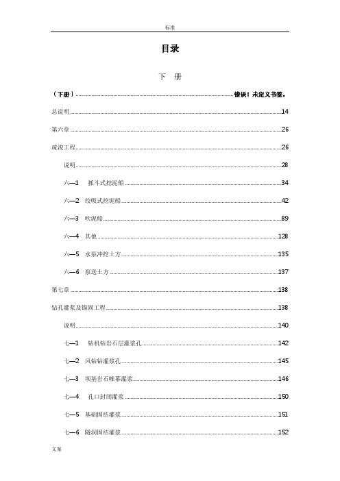
目录下册(下册)......................................................................................................................... 错误!未定义书签。
总说明 (14)第六章 (26)疏浚工程 (26)说明 (28)六—1 抓斗式挖泥船 (34)六—2 绞吸式挖泥船 (42)六—3 吹泥船 (89)六—4 其他 (128)六—5 水泵冲挖土方 (135)六—6 泵送土方 (137)第七章 (138)钻孔灌浆及锚固工程 (138)说明 (140)七—1 钻机钻岩石层灌浆孔 (142)七—2 风钻钻灌浆孔 (145)七—3 坝基岩石帷幕灌浆 (146)七—4 孔口封闭灌浆 (150)七—5 基础固结灌浆 (151)七—6 隧洞固结灌浆 (152)七—8 回填灌浆 (156)七—9 压水试验 (157)七—10 压浆检查 (159)七—11 钻机钻土坝(堤)灌浆孔 (161)七—12 土坝(堤)充填灌浆 (162)七—13 锥探灌浆 (163)七—14 钻机钻(高压喷射)灌浆孔 (165)七—15 高喷灌浆 (166)七—16 坝基砂砾石帷幕灌浆 (167)七—17 灌注孔口管 (168)七—18 地下连续墙成槽——冲击钻机成槽法 (172)七—19 地下连续墙成槽——冲击钻机配合液压抓斗成槽法 (174)七—20 地下连续墙成槽——液压抓斗成槽法 (181)七—21 地下连续墙成槽-振动沉模防渗板墙 (185)七—22 地下连续墙—深层水泥搅拌桩防渗墙 (189)七—23 混凝土防渗墙浇筑 (192)七—24 预裂爆破 (194)七—25 振冲碎石桩 (195)七—26 振冲水泥碎石桩 (197)七—27 振冲挤密砂桩 (198)七—28 水泥搅拌桩 (201)七—30 塑料排水板 (204)七—31 打、压预制钢筋混凝土方桩 (206)七—32 机械、人工打圆木桩 (209)七—33 冲击钻造灌注桩孔 (211)七—34 回旋钻造灌注桩孔 (213)七—35 灌注混凝土桩 (215)七—36 坝体接缝灌浆 (216)七—37 预埋骨料灌浆 (218)七—38 水位观测孔工程 (219)七—39 土坝(堤)测压管 (220)七—40 地面砂浆锚杆——风钻钻孔 (222)七—41 地面药卷锚杆——风钻钻孔 (228)七—42 地面砂浆锚杆——履带钻钻孔 (234)七—43 地面长砂浆锚杆——锚杆钻机钻孔 (241)七—44 地面砂浆锚杆(利用灌浆孔) (247)七—45 加强长砂浆锚杆束——地质钻机钻孔 (248)七—46 地面自进式砂浆锚杆——风钻钻孔 (253)七—47 地下砂浆锚杆——锚杆台车钻孔 (259)七—48 岩体预应力锚索——无粘结型 (264)七—49 岩体预应力锚索——粘结型 (267)七—50 混凝土预应力锚索 (270)七—52 管棚 (273)七—53 管棚注浆 (275)七—54 岩石面喷浆 (276)七—55 混凝土面喷浆 (279)七—56 地面护坡喷混凝土 (282)七—57 平洞喷混凝土 (285)七—58 斜井喷混凝土 (288)第八章 (291)生态绿化工程 (291)说明 (292)八—1 水平阶整地 (293)八—2 水平沟整地 (295)八—3 草皮铺种 (295)八—4 人工直播种草 (296)八—5 苗木运输 (297)八—6 植苗造林 (298)八—7 栽植苗木 (300)八—8 分植造林、栽植经济林 (301)八—9 露地花卉栽植 (302)八—10 栽植绿篱 (302)八—11 栽植攀缘植物 (304)八—13 树木支撑 (306)八—14 格宾网装乱石护岸 (306)八—15 植生带护坡 (308)八—16 三维植被网护坡 (309)八—17 土工格栅植草护坡 (311)第九章 (313)管道工程 (313)说明 (314)九—1 成品钢管管道铺设 (315)九—2 塑料管道及管件安装 (317)九—3 预应力(自应力)混凝土管管道铺设 (321)九—4 预应力钢筒混凝土管(PCCP)管道铺设 (323)九—5 玻璃钢管管道铺设 (325)九—6 球墨铸铁管管道铺设 (328)九—7 混凝土管安装 (332)九—8 顶管 (334)第十章 (342)其他工程 (342)说明 (343)十—1 袋装土石围堰 (344)十—2 软体沉排 (345)十—4 公路路面 (347)十—5 路缘石安装 (350)十—6 水泥地砖铺设 (351)十—7 复合柔毡铺设 (351)十—8 土工膜铺设 (352)十—9 土工布铺设 (352)十—10 塑料薄膜铺设 (353)十—11 土工格栅铺设 (353)十—12 聚苯乙烯保温板 (354)十—13 PVC滤水(排水)管 (355)十—14 打桩工作平台 (356)十—15 管道铺设 (357)十—16 照明线路工程 (363)十—17 吹砂充填模袋 (364)十—18 铁道铺设、拆除 (365)十—19 轻型井点排水 (366)十—20 深井排水 (367)十—21 蓄水池 (369)附录 (371)附录1 土石方松实系数 (371)附录2 一般工程土类分级 (372)附录4 (377)附录5 河道疏浚工程分级表 (379)附录6 混凝土、砂浆配合比及材料用量表 (383)1、混凝土配合比有关说明 (383)①埋乱石混凝土材料量=配合表列材料用量×(1-埋乱石率%) (383)②因埋乱石增加的人工见表6-2。


I-108-CHI安装说明108 型 FireLock ™ IGS ™ Installation-Ready ™刚性接头重要信息上图并非按照管道和沟槽的实际比例绘制108 型 FireLock ™ IGS ™ Installation-Ready ™ 刚性接头仅应用于按照Victaulic (唯特利)IGS 专有沟槽规格准备的对接件。
请勿尝试将该接头安装在按照其他沟槽规格制备的对接件上。
有关IGS 沟槽规格,请参阅可从 下载的Victaulic (唯特利)25.14号技术文件。
请勿将 108 型接头用于喷淋头与喷淋头之间的管道连接。
对于喷淋头连接,请使用 V9 型接头。
108 型接头的首次安装说明1.请勿拆解接头:108 型接头的设计使安装人员无需拆卸螺母、螺栓和连锁即可完成安装。
此设计允许安装人员直接将对接件的沟槽端头插入接头,安装更加便利。
2.检查对接件的端头:对接件沟槽至端头之间的外表面必须无任何压痕、凸起、焊缝异常和辊印,以确保完全无泄漏密封。
应清除所有机油、油脂、脱落油漆、污垢及切屑。
对接件外径(“OD ”)、沟槽尺寸和最大允许喇叭口直径必须在最新发布的25.14号技术文件 [Victaulic (唯特利)IGS 规格]规定的公差范围之内,该文件可从下载。
材料等级色码标记3.检查密封垫圈:检查密封垫圈,确 保其适合预期用途。
色码标明了密封垫圈的等级。
请参阅 Victaulic ( 唯特利)05.01 号技术文件查看颜色代码表(文件可在 下载),并参阅下一页中的“注意事项”了 解密封垫圈的重要信息。
3a.若存在“注意事项”中的任一情况,请在密封垫圈的密封唇缘上涂抹薄薄一层兼容润滑剂(如 Victaulic ( 唯特利)润滑剂或硅润滑剂)。
注意事项• 108 型接头提供Vic-Plus 密封垫圈。
当用于湿管系统的首次安装时,如果安装温度或连续工作温度高于 0ºF/-18º C ,则无需进行额外润滑。


C80级高性能泵送混凝土的配制及试验研究[提要]近年随着建筑技术的不断发展,混凝土技术也朝着多性能、高性能混凝土(HPC)方面发展,目前国内外有关高强、高性能混凝土(HPC)的研究及应用发展很快,国际上在工程上获得使用的混凝土强度已达到100~130MPa,在我国C80级混凝土已被建设部定为“九.五”重点推广项目,而C60级混凝土我们于1995年进行了研制,并成功地应用于航华科贸中心、静安大厦等工程,并且荣获科技进步一等奖。
为适应现代化建设的需要,提高混凝土技术水平,增加技术储备,我们在1998年开始研制C80级高性能混凝土(HPC)的试验研究,目前已通过鉴定,通过大量的试配,得到了一套完整的数据,获得了理想的结果。
1、原材料的选择根据原材料质量、供应能力、资源等,优选以下几种原材料进行C80级混凝土的配制。
1.1 水泥选用质量稳定、活性较高的琉璃河水泥厂的普硅525R水泥和怀北水泥厂拉法基普硅525R 水泥,其物理学性能如表1。
(1)砂:选用级配良好的怀柔龙凤山分厂的中粗砂,其技术指标见表2。
表2 砂子技术指标2、外加剂的选择通过市场调研及混凝土试拌初步选定以下4种高性能外加剂,结合本单位混凝土生产工艺均选用液体外加剂,其品种与基本性能见表4。
表4中的外加剂掺量均为按液体计。
在前期的混凝土试配工作中,采用这四种外加剂,在相同原材料和等稠度条件下进行对比试验,其结果列于表5。
表4 外加剂品种与性能表5 高性能外加剂对比试验强度值从试验得出以RH-8所配制的混凝土过粘,以C-SF配制的混凝土流动性差,JL118及DFS-Ⅱ早期强度高,且与各种细掺料及选定的水泥适应性良好,由此我们选择了JL118和DFS-Ⅱ两种外加剂。
3、细掺料的选择在原材料及外加剂选定之后,我们采用10种细掺料(多为复合型),进行对水泥、外加剂的适应性试验,经综合分析,选择Z-1、Z-2、Z-6、Z-8、Z-8′及Z-9六种细掺料,其试验结果见表6和表7。

SL2128C⾼性能电流模式PWM开关电源控制器概述采⽤双极⼯艺制造、内建防过载、防饱和电路,能满⾜绿⾊环保标准的开关电源控制器;为提⾼电路性能参数的⼀致性,对内部基准电压进⾏了特别设计,以提⾼内部基准电压的精度。
采⽤宽电源(85--265)设计,典型输出功率12W,最⾼输出功率可达15W,峰值输出功率18W。
⼴泛使⽤于经济型开关电源,如DVD、机顶盒、传真机、打印机、LCD显⽰器等。
特点●内建防过载、饱和电路,能及时防范过载、开关变压器饱和、输出短路等故障●采⽤700V耐压的双极型三极管作为开关管;同时利⽤其放⼤作⽤完成启动,并使启动电阻的功耗减⼩10倍以上●开关管内置,减少成本,提⾼电路性价⽐●内置斜坡补偿电路、热保护电路、斜坡电流驱动电路●内置热保护电路●低启动和⼯作电流●VCC过压⾃动限制●⽆输出功耗⼩于0.15W●极少的外围元器件●封装形式:DIP8应⽤引脚图●中⼩功率AC/DC开关电源●充电器、外置电源盒●DVD、DVB电源●⼩功率适配器●PC、TV 等电器的辅助电源●线性调节器/替代RCC 变换器SL2128C典型应⽤▲:PCB Layout时应将Pin6与Pin7之间保留1mm以上的安全距离,避免产⽣放电现象.SL2128C内部框图极限参数SL2128C推荐⼯作条件电特性(TA=25℃,VDD=5.5-7.5V,RS=1Ω)输出部分参考部分振荡器部分反馈部分电流取样部分脉宽调制部分电源电流注:如电路性能有所更新,电参数有所改动,不作另外说明。
封装尺⼨图。


不锈钢牌号对照表
精选文档,供参考!
精选文档,供参考!
精选文档,供参考!
精选文档,供参考!
精选文档,供参考!
世界金属牌号对照表碳素结构钢
精选文档,供参考!
精选文档,供参考!
[返回]
优质碳素结构钢
精选文档,供参考!
精选文档,供参考!
精选文档,供参考!
精选文档,供参考!
精选文档,供参考!
精选文档,供参考!
[返回]
碳素工具钢
精选文档,供参考!
精选文档,供参考!
[返回]
合金结构钢
精选文档,供参考!
精选文档,供参考!
精选文档,供参考!
精选文档,供参考!
精选文档,供参考!
精选文档,供参考!
精选文档,供参考!
[返回]
淬透性合金结构钢
精选文档,供参考!
精选文档,供参考!
[返回]
精选文档,供参考!
弹簧钢
精选文档,供参考!
[返回]
滚动轴承钢
精选文档,供参考!
[返回]
高速工具钢
精选文档,供参考!
精选文档,供参考!
[返回]
不锈耐酸钢
精选文档,供参考!
精选文档,供参考!
精选文档,供参考!
精选文档,供参考!
[返回]
耐热钢
精选文档,供参考!
精选文档,供参考!
[返回]
精选文档,供参考!
易切结构钢
精选文档,供参考!
合金工具钢
精选文档,供参考!
精选文档,供参考!
精选文档,供参考!
(此文档部分内容来源于网络,如有侵权请告知删除,文档可自行编辑修改内容,供参考,感谢您的支持)
精选文档,供参考!。

CRTⅢ型板式无砟轨道首件段施工方案新建商丘至合肥至杭州铁路X标一分部CRTSⅢ型无砟轨道首件段施工方案编制:复核:审准:X集团新建商丘至合肥至杭州铁路X标段项目经理部一分部二〇一八年三月目录CRTSⅢ型板式无砟轨道首件段施工方案 .................................................... - 4 -一、编制依据 .............................................................................................. - 4 -二、工程概况及编制范围 ............................................................................ - 4 -2.1 工程概况........................................................................................................................... .......... - 4 -2.2 编制范围........................................................................................................................... .......... - 5 -三、总体施工安排 ....................................................................................... - 5 -3.1 组织机构........................................................................................................................... ........ - 5 -3.2 主要施工任务........................................................................................................................... - 6 -3.3 总体施工计划........................................................................................................................... - 6 -3.4 主要临时工程........................................................................................................................... - 6 -3.5临时用电用水........................................................................................................................... ... - 7 -四、主要工程数量及施工工艺 ..................................................................... - 7 -4.1 主要工程数量........................................................................................................................... ... - 7 -4.1.1 轨道板数量........................................................................................................................... - 7 -4.1.2主要材料数量........................................................................................................................ - 7 -4.2 主要施工工艺........................................................................................................................... .. - 8 -五、施工准备 .............................................................................................. - 8 -5.1 桥梁地段CPⅢ的布标与埋设.................................................................................................... - 8 -5.2 CPⅢ测量........................................................................................................................... ........... - 9 -5.2.1 平面网测量........................................................................................................................... - 9 -5.2.2 高程网测量......................................................................................................................... - 12 -5.2.3 CPⅢ评估........................................................................................................................... .. - 15 -5.3 核对设计文件............................................................................................................................ - 15 -5.4 技术交底........................................................................................................................... ......... - 15 -5.5岗前培训........................................................................................................................... .......... - 15 -5.6 工艺性试验........................................................................................................................... ..... - 15 -5.7铺设条件评估、接口验收 ......................................................................................................... - 16 -六、资源配置 ............................................................................................ - 16 -6.1人员配置........................................................................................................................... .......... - 16 -6.2 机械配置 ................................................................................................................................... - 18 -6.3物资调配措施........................................................................................................................... .. - 18 -七、主要施工工艺 ..................................................................................... - 20 -7.1底座施工........................................................................................................................... .......... - 20 -7.1.1梁面凿毛及测量放线.......................................................................................................... - 20 -7.1.2套筒连接及梁面植筋.......................................................................................................... - 20 -7.1.3底座钢筋焊网加工及铺设 .................................................................................................. - 21 -7.1.4底座模板安装...................................................................................................................... - 22 -7.1.5 底座板限位凹槽模板安装 ................................................................................................. - 23 -7.1.6底座混凝土浇筑.................................................................................................................. - 23 -7.1.7底座混凝土拆模及养护 ...................................................................................................... - 23 -7.1.8底座伸缩缝设置.................................................................................................................. - 24 -7.1.9底座验收........................................................................................................................... ... - 24 -7.2中间隔离层及弹性垫层施工 ..................................................................................................... - 24 -7.3限位凹槽及焊网钢筋存放以及制作要求 ................................................................................. - 25 -7.4 轨道板检验........................................................................................................................... ..... - 25 -7.5 轨道板铺设........................................................................................................................... ..... - 25 -7.5.1轨道板粗铺.......................................................................................................................... - 25 -7.5.2 轨道板精调......................................................................................................................... - 26 -7.6自密实混凝土技术要求 ............................................................................................................. - 27 -7.6.1原材料技术要求.................................................................................................................. - 27 -7.6.2自密实混凝土性能要求 ...................................................................................................... - 29 -7.6.2自密实混凝土灌注质量要求 .............................................................................................. - 30 -7.7 自密实混凝土配制.................................................................................................................... - 31 -7.7.1一般规定........................................................................................................................... ... - 31 -7.7.2配合比要求.......................................................................................................................... - 31 -7.8 自密实混凝土施工工艺 ............................................................................................................ - 32 -7.8.1 自密实混凝土施工工艺流程 ............................................................................................. - 32 -7.8.2施工要求........................................................................................................................... ... - 32 -7.8.3轨道板压紧限位装置.......................................................................................................... - 32 -7.8.4轨道板封边及预留排气孔 .................................................................................................. - 33 -7.8.5轨道板板腔润湿.................................................................................................................. - 33 -7.8.6自密实混凝土施工准备 ...................................................................................................... - 33 -7.8.7混凝土拌合.......................................................................................................................... - 34 -7.8.8混凝土运输.......................................................................................................................... - 35 -7.8.9混凝土灌注.......................................................................................................................... - 35 -7.8.10 自密实混凝土灌注后质量验收 ....................................................................................... - 37 -八、施工质量保证措施.............................................................................. - 37 -8.1 施工注意事项............................................................................................................................ - 37 -8.1.1混凝土底座及限位凹槽施工技术保证措施 ...................................................................... - 38 -8.1.2中间隔离层及弹性垫层施工技术保证措施 ...................................................................... - 38 -8.1.3自密实混凝土施工技术措施 .............................................................................................. - 38 -8.2 离缝现象控制............................................................................................................................ - 39 -8.3气泡现象控制........................................................................................................................... .. - 39 -8.4泌水现象控制........................................................................................................................... .. - 39 -8.5灌注不饱满控制......................................................................................................................... - 40 -8.6原材料检验........................................................................................................................... ...... - 40 -8.7 施工总结........................................................................................................................... ......... - 42 -九、安全、环保、水土保持和文明施工保证措施 ...................................... - 42 -9.1安全保证措施........................................................................................................................... .. - 42 -9.2 环境保护措施............................................................................................................................ - 43 -9.3水土保持措施........................................................................................................................... .. - 43 -9.4文明施工........................................................................................................................... .......... - 44 -十、安全、环境危险源辨识及处理措施..................................................... - 45 -CRTSⅢ型板式无砟轨道首件段施工方案一、编制依据1、《铁路混凝土结构耐久性设计规范》(TB10005-2010)2、《CRTSⅢ型板式无砟轨道自密实混凝土暂行技术条件》(TJ/GW112-2013)3、《钢筋焊接网混凝土结构技术规程》(JGJ114-2014)4、《钢筋混凝土用钢筋焊接网》(GB/T1499.3-2010)5、《冷轧带肋钢筋》(GB13788-2008)6、《冷轧带肋钢筋混凝土结构技术规程》(JGJ95-2011)7、《高速铁路CRTSⅢ型板式无砟轨道隔离层用土工布暂行技术条件》(TJ/GW113-2013)8、《高速铁路CRTSⅢ型板式无砟轨道弹性缓冲垫层暂行技术条件》(TJ/GW114-2013)9、《高速铁路无砟轨道嵌缝材料暂行技术条件》(TJ/GW119-2013)10、《客运专线铁路无砟轨道铺设条件评估技术指南》(铁建设[2006]158号)11、《高速铁路轨道工程施工技术规程》(Q/CR9605-2017)12、《铁路混凝土工程施工质量验收标准》(TB10424-2010)13、《CRTSⅢ型板式无砟轨道工程施工质量验收指导意见(试行)》(工管线路函[2012]159号)14、《高速铁路轨道工程施工质量验收标准》(TB10754-2010)15、《混凝土结构后锚技术规程》(JGJ145-2013)16、京福公司下发有关文件及设计相关文件、施工图。


高性能电流模式PWM开关电源控制器
概述
采用双极工艺制造、内建防过载、防饱和电路,能满足绿色环保标准的开关电源控制器;为提高电路性能参数的一致性,对内部基准电压进行了特别设计,以提高内部基准电压的精度。
采用宽电源(85--265)设计,典型输出功率12W,最高输出功率可达15W,峰值输出功率18W。
广泛使用于经济型开关电源,如DVD、机顶盒、传真机、打印机、LCD显示器等。
特点
●内建防过载、饱和电路,能及时防范过载、开关变压器饱和、输出短路等故障
●采用700V耐压的双极型三极管作为开关管;同时利用其放大作用完成启动,并使启动电阻的功耗减小
10倍以上
●开关管内置,减少成本,提高电路性价比
●内置斜坡补偿电路、热保护电路、斜坡电流驱动电路
●内置热保护电路
●低启动和工作电流
●VCC过压自动限制
●无输出功耗小于0.15W
●极少的外围元器件
●封装形式:DIP8
应用引脚图
●中小功率AC/DC开关电源
●充电器、外置电源盒
●DVD、DVB电源
●小功率适配器
●PC、TV 等电器的辅助电源●线性调节器/替代RCC 变换器
SL2128C
典型应用
▲:PCB Layout时应将Pin6与Pin7之间保留1mm以上的安全距离,避免产生放电现象.
SL2128C内部框图
极限参数
SL2128C推荐工作条件
电特性
(TA=25℃,VDD=5.5-7.5V,RS=1Ω)
输出部分
参考部分
振荡器部分
反馈部分
电流取样部分
脉宽调制部分
电源电流
注:如电路性能有所更新,电参数有所改动,不作另外说明。
封装尺寸图。