APPLICATION IN VIRTUAL COCKPIT
- 格式:pdf
- 大小:289.30 KB
- 文档页数:4
中英文资料外文翻译Internet of Things1.the definition of connotationThe English name of the Internet of Things The Internet of Things, referred to as: the IOT.Internet of Things through the pass, radio frequency identification technology, global positioning system technology, real-time acquisition of any monitoring, connectivity, interactive objects or processes, collecting their sound, light, heat, electricity, mechanics, chemistry, biology, the location of a variety of the information you need network access through a variety of possible things and things, objects and people in the Pan-link intelligent perception of items and processes, identification and management. The Internet of Things IntelliSense recognition technology and pervasive computing, ubiquitous network integration application, known as the third wave of the world's information industry development following the computer, the Internet. Not so much the Internet of Things is a network, as Internet of Things services and applications, Internet of Things is also seen as Internet application development. Therefore, the application of innovation is the core of the development of Internet of Things, and 2.0 of the user experience as the core innovation is the soul of Things.2.The meaning of "material"Where the "objects" to meet the following conditions can be included in the scope of the "Internet of Things":1. Receiver have the appropriate information;2. Have a data transmission path;3. Have a certain storage capabilities;4. T o have the CPU;5.T o have the operating system;6. Have specialized applications;7. Have a data transmitter;8. Follow the communication protocol of Things;9. World Network, a unique number that can be identified.3. "Chinese style" as defined inInternet of Things (Internet of Things) refers to is the ubiquitous (Ubiquitous) terminal equipment (Devices) and facilities (Facilities), including with the "inner intelligence" sensors, mobile terminals, industrial systems, floor control system, the family of Intelligentfacilities, video surveillance systems, and external can "(Enabled), such as RFID, a variety of assets (the Assets), personal and vehicle carrying the wireless terminal" intelligent objects or animals "or" smart dust "(the Mote), through a variety of wireless and / or cable over long distances and / or short-range communication networks to achieve interoperability (M2M), application integration (the Grand Integration), and based on cloud computing, SaaS operation mode, in internal network (intranet), private network (e xtranet), and / or the Internet (Internet) environment, the use of appropriate information security mechanisms to provide a safe, controlled and even personalized real-time online monitoring, retrospective positioning, alarm linkage, command and control plan management, remote control, security, remote repair and maintenance, online upgrades, statistical reporting, decision support, the leadership of the desktop (showcase of the Cockpit Dashboard) management and service functions, "Everything," "efficient, energy saving, security environmental protection, "" possession, control, Camp integration [1].4.EU definitionIn September 2009, the Internet of Things and enterprise environments held in Beijing, China-EU Seminar on the European Commission and Social Media Division RFID Division is responsible for Dr. Lorent Ferderix, given the EU's definition of things: the Internet of Things is a dynamic global network infrastructure, it has a standards-based and interoperable communication protocols, self-organizing capabilities, including physical and virtual "objects" of identity, physical attributes, virtual features and smart interface and seamless integration of information networks . Internet of Things Internet and media, the Internet and business Internet one, constitute the future of the Internet.5.changeThe Internet of Things (Internet of Things) the word universally recognized at home and abroad Ashton, Professor of the MIT Auto-ID Center in 1999 first proposed to study RFID. The report of the same name released in 2005, the International T elecommunication Union (ITU), the definition and scope of the Internet of Things has been a change in the coverage of a larger expansion, no longer refers only to the Internet of Things based on RFID technology.Since August 2009, Premier Wen Jiabao put forward the "Experience China" Internet of Things was officially listed as a national one of the five emerging strategic industries, to write the "Government Work Report" Internet of Things in China has been the great concern of the society as a whole degree of concern is unparalleled in the United States, European Union, as well as other countries.The concept of Internet of Things is not so much a foreign concept, as it has been the concept of a "Made in China", his coverage of the times, has gone beyond the scope of the 1999 Ashton professor and the 2005 ITU report referred to, Internet of Things has been labeled a "Chinese style" label.6.BackgroundThe concept of Internet of Things in 1999. Internet-based, RFID technology and EPC standards, on the basis of the computer Internet, the use of radio frequency identification technology, wireless data communication technology, a global items of information to real-time sharing of the physical Internet "Internet of things" (referred to as the Internet of Things) , which is also the basis of the first round of the China Internet of Things boom set off in 2003.The sensor network is built up based on sensing technology network. Chinese Academy of Sciences in 1999 on the start sensor network research and has made some achievements in scientific research, the establishment of applicable sensor network.1999, held in the United States, mobile computing and networking International Conference, "The sensor network is a development opportunity facing humanity in the next century. In 2003, the United States, "T echnology Review" proposed sensor network technology will be future changes ten people's lives first.November 17, 2005, the WSIS held in Tunis (WSIS), the International T elecommunication Union released ITU Internet Report 2005: Internet of Things ", citing the concept of the" Internet of things ". The report pointed out that the ubiquitous "Internet o f Things" communication era is approaching, all the objects in the world, from tires to toothbrushes, from housing to the tissue via the Internet, take the initiative to be exchanged. Radio Frequency Identification (RFID), sensor technology, nanotechnology, intelligent embedded technology will be more widely used.According to the description of the ITU, the era of things, a short-range mobile transceivers embedded in a variety of daily necessities, human beings in the world of information and communication will receive a new communication dimension, from any time communication between people of the place of connection extended to the communication connection between persons and things and things and things. The Internet of Things concept of the rise, largely due to the International T elecommunication Union (ITU), the title of Internet of Things 2005 annual Internet Report. However, the ITU report the lack of a clear definition of Things.Domestic Internet of Things is also there is no single standard definition, but the Internet of Things In essence, the Internet of Things is a polymer application of modern information technology to a certain stage of development and technological upgrading of various sensing technology modern network technology and artificial intelligence and automation technology aggregation and integration of applications, so that the human and material wisdom of dialogue to create a world of wisdom. Because the development of the Internet of Things technology, involving almost all aspects of IT, innovative application and development of a polymer, systematic, and therefore be called revolutionary innovation of information industry. Summed up the nature of the Internet of Things is mainly reflected in three aspects: First, the Internet features that need to be networked objects must be able to achieve the interoperability of the Internet; identification and communication features, that is included in the Internet of Things "objects" must to have the functions of automatic identification and physical objects communication (M2M); intelligent features, the network system should have automated, self-feedback and intelligent control features January 28, 2009, Obama became the President of the United States, held with U.S.business leaders a "round table", as one of the only two representatives, IBM CEO Sam Palmisano for the first time that "the wisdom of the Earth" this concept, it is recommended that the new government to invest in a new generation of intelligent infrastructure.February 24, 2009 news, IBM Greater China CEO money crowd called "Smarter Planet" strategy announced in the forum 2009IBM.This concept was put forth, that is the great concern of the United States from all walks of life, and even analysts believe that IBM's vision is very likely to rise to U.S. national strategy, and caused a sensation in the world. IBM believes that the industry, the next phase of the mission is to make full use of the new generation of IT technology in all walks of life among specifically, is the embedded sensors and equipment to the power grid, railways, bridges, tunnels, highways, buildings, water supply systems dams, oil and gas pipelines and other objects, and is generally connected to the formation of Things.Strategy conference, IBM, and implant the concept of "wisdom" in the implementation of the infrastructure, strong, not only in the short term to stimulate the economy, promote employment, and in a short period of time for China to build a mature wisdom infrastructure platform.IBM "Smarter Planet" strategy will set off again after the wave of Internet technology industrial revolution. Former IBM CEO Lou Gerstner has raised an important point of view, every 15 years, a revolution in computing model. This judgment is the same as Moore's Law accurately call it a "15-year cycle Law". Before and after 1965, changes to the mainframe as a symbol, 1980 marked by the popularization of personal computers, 1995, the Internet revolution. Each such technological change are caused by the enterprise, industry and even the national competitive landscape of major upheaval and change. T o a certain extent in the Internet revolution is ripening by the "information superhighway" strategy. 1990s, the Clinton administration plan for 20 years, $ 200 billion to -4000 billion, construction of the U.S. National Information Infrastructure, to create a huge economic and social benefits.T oday, the "Smarter Planet" strategy by many Americans that there are many similarities with the "information superhighway", the same they revive the economy, a key strategy for competitive advantage. The strategy can be set off, not only for the UnitedStates, such as the Internet revolution was the wave of technological and economic concern, more attention from the world."Internet of Things prospects are very bright, it will dramatically change our current way of life." Demonstration director of the Center of Nanjing University of Aeronautics and Astronautics, National Electrical and Electronic Zhao Guoan said. Industry experts said that the Internet of things to our life personification of the things became a kind of human.Goods (goods) in the world of physical objects associated with each other "exchange", without the need for human intervention. The Internet of Things using radio frequency identification (RFID) technology, to achieve the interconnection and sharing of the automatic identification of goods (products) and information through the computer Internet. It can be said that the Internet of Things depict the world is full of intelligent. In the world of Internet of Things, material objects connected to the dragnet.The second session, held at Peking University in November 2008, China Mobile Government Seminar "Knowledge Society and Innovation 2.0", the experts made the mobile technology, the Internet of Things technology led to the development of economic and social form, innovative forms of change, and promote the The next generation of innovation for the knowledge society as the core of user experience (innovative 2.0) the formation of innovation and development of the form to pay more attention to the user to focus on people-oriented. Research institutions is expected to 10 years, the Internet of Things may be mass adoption of this technology will develop into one of thousands of yuan-scale high-tech market, the industry than the Internet 30 times.It is learned that the things industry chain can be broken down into the identity, perception, processing and information transfer, four links, each link of the key technologies for the wireless transmission network of RFID, sensors, smart chip and telecom operators. EPOSS in the "Internet of Things in 2020" report, an analysis predicted that the future development of the Internet of Things will go through four stages, 2010, RFID is widely used in the field of logistics, retail and pharmaceutical objects interconnect 2010 to 2015, 2015 ~ In 2020, the object into the semi-intelligent, intelligent objects into 2020.As the vanguard of the Internet of Things, RFID has become the most concerned about the technology market. The data show that the global RFID market size in 2008 from$ 4.93 billion in 2007 rose to $ 5.29 billion, this figure covers all aspects of the RFID market, including tags, readers and other infrastructure, software and services. RFID card and card-related infrastructure will account for 57.3 percent of the market, reaching $ 3.03 billion. Application from financial and security industries will drive the market growth of RFID cards. Analysys International forecasts, the Chinese RFID market size in 2009 will reach 5.0 billion, a CAGR of 33%, in which the electronic tag is more than 3.8 billion yuan, the reader close to 700 million yuan, software and services market to reach 500 million yuan pattern.MEMS is the abbreviation of the micro-electromechanical systems, MEMS technology is built on the basis of micro / nano, the market prospect is broad. The main advantage of the MEMS sensor is the small size, large-scale mass production cost reduction, mainly used in two major areas of automoti ve and consumer electronics. Under ICInsight the latest report is expected in 2007-2012, global sales of semiconductor sensors and actuators based on MEMS will reach 19 percent compound annual growth rate (CAGR), compared with $ 4.1 billion in 2007 to five years will achieve $ 9.7 billion in annual sales. 7.PrincipleInternet of Things is on the basis of the computer Internet, RFID, wireless data communications technology, to construct a cover everything in the world's "Internet of Things". In this network, the goods (products) to each other "exchange", without the need for human intervention. Its essence is the use of radio frequency identification (RFID) technology to achieve the interconnection and sharing of the automatic identification of goods (products) and information through the computer Internet.The Internet of Things is a very important technology is radio frequency identification (RFID) technology. RFID is radio frequency identification (Radio Frequency Identification) technology abbreviation, is an automatic identification technology in the 1990s began to rise, the more advanced a non-contact identification technology. The development of RFID technology based on a simple RFID system, combined with existing network technology, database technology, middleware technology, to build a one composed by a large number of networked readers and numerous mobile label, much larger than the Internet of Things trend.RFID, It is able to let items "speak" a technique. In the "Internet of Things" concept, RFID tags are stored in the specification and interoperability information collected automatically by wireless data communications network to a central information system, to achieve the identification of goods (products), and then through the open computer network for information exchange and sharing, items "transparent" management.The information technology revolution in the Internet of Things is referred to as IT mobile Pan of a specific application. Internet of Things through IntelliSense, identification technology and pervasive computing, ubiquitous network convergence applications, breaking the conventional thinking before, human beings can achieve ubiquitous computing and network connectivity [3]. The traditional thinking has been the separation of physical infrastructure and IT infrastructure: on the one hand, airports, roads, buildings, while on the other hand, the data center, PC, broadband. In the era of the "Internet of Things", reinforced concrete, cable with the chip, broadband integration into a unified infrastructure, in this sense, the infrastructure is more like a new site of the Earth, the world really works it, which including economic management, production operation, social and even personal life. "Internet of Things" makes it much more refined and dynamic management of production and life, to manage the future of the city to achieve the status of "wisdom" to improve resource utilization and productivity levels, and improve the relationship between man and nature.8.Agency1, institution-buildingAs the first national Internet of Things industry community organizations - the application of professional Committee of China Electronic Chamber of Things technology products (referred to as: "objects of the IPCC"), the Ministry of Civil Affairs in June 2010, preliminary approved by the Ministry of August being reported that the Ministry of Civil Affairs for final approval.2, the main taskServe as a bridge between business and government to assist the Government of the industry guidance, coordination, consultation and services to help members to reflect the business requirements to the Government; coordinate the relationship between enterprisesto strengthen technical cooperation, product distribution, the elimination of vicious competition ; supervision of members the correct implementation of national laws and regulations, to regulate the industry; member of information communication technology products, cooperation, resource sharing, capital operation, and promote the app lication of Internet of Things technologies and products, and promote the Internet of Things industrial scale , co-development.9.ConstructionInternet of Things in the practical application to carry out requires the involvement of all walks of life, and need the guidance of the national government as well as related regulations and policies to assist the launching of the Internet of Things has the scale, broad participation, management, technical, and material properties, etc. other features, the technical problem is the most crucial issues of Things billion Bo logistics consulting, Internet of Things technology is an integrated technology, a system not yet which company has overall responsibility for network planning and construction of the entire system, theoretical studies have commenced in all walks of life and the practical application is limited to within the industry. The key is on the planning and design and research and development of the Internet of Things research in the field of RFID, sensors, embedded software, and transmission of data calculation. In general, to carry out the steps of the Internet of things mainly as follows:(1) identified the object attributes, properties, including static and dynamic properties of the static property can be stored directly in the label, the dynamic properties need to start with sensors to detect real-time;(2) the need to identify the equipment to complete the reading of object attributes, and information into a data format suitable for network transmission;(3) the object of information transmitted over the network to the information processing center (processing center may be distributed, such as home computers or mobile phones, may also be centralized, such as China Mobile IDC) by the processing center to complete the object communication calculation.10.key areasInternet of Things 4 key areas:(1) RFID;(2) sensor network;(3) The M2M;(4) integration of the two.11.TrendIndustry experts believe that the Internet of things on the one hand can improve economic efficiency and significant cost savings; the other hand, can provide technical impetus to global economic recovery. Currently, the United States, the European Union are all invested heavily in-depth study to explore the Internet of Things. The country is also highly concerned about the emphasis of Things, Industry and Information T echnology Ministry in conjunction with the relevant departments are conducting research in a new generation of IT to the formation of policies and measures to support the development of a new generation of IT.China Mobile CEO Wang Jianzhou has repeatedly mentioned the Internet of Things will become the focus of future development of China Mobile. He will be invited to T aiwan to produce RFID, sensors and bar code manufacturers and China Mobile. According to him, the use of the Internet of Things technology, Shanghai Mobile has a number of industrial customers tailor the data collection, transmission, processing and business management in one set of wireless application solutions. The latest data show that Shanghai Mobile has more than 100,000 chips mounted on a taxi, bus, various forms of matter networking applications in all walks of prowess, to ensure the orderly operation of the city. During the Shanghai World Expo, "the bus services through" will be fully applied to the Shanghai public transport system, the smooth flow traffic to the most advanced technology to protect Expo area; for logistics transportation management, e-logistics ", will provide users with real-time accurate information of Cargo, vehicle tracking and positioning, the transport path selection, logistics network design and optimization services greatly enhance the comprehensive competitiveness of logistics enterprises.In addition, the popularization of the "Internet of Things" for the number of animals, plants and machinery, sensors and RFID tags of items and related interface devices will greatly exceed the number of mobile phones. The promotion of the Internet of Things willbecome a drive to promote economic development for the industry to open up a potential development opportunities. According to the current demand on the Internet of Things, in recent years, billions of sensors and electronic tags, which will greatly promote the production of IT components, while increasing the number of job opportunities.According to reports, it is necessary to truly build an effective Internet of things, there are two important factors. First, the scale, only with the scale to make the items of intelligence play a role. For example, a city of one million vehicles, if we only 10000 vehicles installed on the smart system, it is impossible to form an intelligent transportation system; two mobility items are usually not static, but in the state of the movement , we must maintain the items in the state of motion, and even high-speed motion state can at any time for dialogue.FORRESTER of the authority of the U.S. advisory body predicted that 2020, the world of business of the Internet of Things, compared with the business of interpersonal communication, will reach 30 to 1, so the "Internet of Things" is known to be the next one trillion communications services.Internet of Things heat wave Why is rapidly growing in China? Internet of Things in China rapid rise thanks to the several advantages of our country in terms of things.In the early 1999 launched the Internet of Things core sensor network technology research, R & D level in the world; the second, sensor network field in the world, China is the standard one of the dominant country, the patent owner; third China is one of the countries to achieve a complete industrial chain of Things; Fourth, China's wireless communications network and broadband coverage provides a solid infrastructure to support the development of the Internet of Things; Fifth, China has become the world's first the three major economies, with strong economic strength to support the development of the Internet of Things.12.MythThe current understanding of the Internet of things there are a lot of misunderstanding, which is also a direct impact on our understanding of Things on the development of the logistics industry, it is necessary first to distinguish errors, clarify our thinking.One sensor networks or RFID network equivalent of Things. The fact that sensortechnology, or RFID technology, or are simply one of the information collection technology. In addition to the sensor technology and RFID technology, GPS, video recognition, infrared, laser, scanning can be achieved automatically identify physical objects to communicate technical information collection technology can become the Internet of Things. Sensor networks or RFID network is just an application of Things, but not all of Things.Second, the Internet of Things as a myriad of unlimited extension of the Internet of Things as a completely open for all things, all of the interconnections, all shared Internet platform.In fact, the Internet of Things is not simple infinite extension of the global sharing of the Internet. Even if the Internet is also not only refers to we typically think of the international sharing computer network, Internet, WAN and LAN. Internet of Things can be both an extension of our usual sense of the Internet to the matter; LAN, professional can also be based on real needs and industrial applications. The reality is not necessary and can not make all the items networking; no need to make professional, LAN must be connected to the global Internet sharing platform. Of things in the future the Internet will be very different from the professional network of similar smart logistics, smart transportation, smart grid; the intelligence community and other local area network is the largest use of space.T er, that the ubiquitous network of the Internet of Things Internet of Things, and therefore the Internet of Things is a castle in the air, is difficult to achieve the technology. In fact the Internet of things are real, many of the primary Internet of Things applications already for our services. The Internet of Things concept is introduced in many real-world applications based on polymeric integrated innovation, pre-existing network with the Internet of Things, intelligent, automated system, summarized and upgrading it upgraded from a higher perspective our knowledge.Four of Things as a basket, and everything installed inside; based on self-awareness, and only be able to interact, communication products as the Internet of Things applications. For example, just embedded some of the sensors, to become the so-called Internet of Things appliances; products labeled with RFID tags, became the Internet of Things applications.es。

A SINGLE PC SOLUTION FOR RAPID CONTROL PROTOTYPING IN WINDOWS ®.QUARC generates real-time code directly from Simulink®-designed controllers and runs the generated code in real-time on the Windows® target - all on the same PC. The Data Acquisition Card seamlessly interfaces with Simulink® using Hardware-in-the-loop blocks provided in the QUARC T argets Library.SPLIT SECOND CONTROL DESIGN – A DECADE IN ThE MAkINGQUARC was built on the legacy of WinCon, the first real-time software to run Simulink®-generated code in Windows®. QUARC seamlessly integrates with Simulink® and redefines the traditional design-to-implementation interface toolset. Just click a button to enjoy more functionality and development flexibility, all geared towards improved real-time performance. Academics havesuccessfully deployed many advanced control and mechatronic systems, ranging from intelligent unmanned systems to force-feedback-enabled virtual reality.ADVANCEDINDUSTRIAL R&DACADEMIA INDUSTRYFOUR USES OF QUARCCONTROLS EDUCATION INNOVATIVERESEARCH GRADUATE-LEVEL EXPLORATION Enhance your engineering courses with industry- relevant hands-on learning Explore practical solutions for real-life challenges with a synergistic approachConduct ground-breaking research in emerging areas such as Unmanned Vehicle Systems and hapticsFast track time-to-market with an affordable rapid control prototyping solutionChoosing software for control system design andimplementation is critical for timely, successful research and development. Quanser knows this because we’ve pioneered control engineering for over 20 years. That’s why we created QUARC – a powerful rapid control prototyping tool that significantly accelerates control design and implementation. initially designed for industrial demands, QUARC is nonetheless ideal foradvanced research, masters-level, and evenundergraduate, teaching. QUARC is an integral part of all Quanser control lab workstations and is used all over the world by thousands of educational institutions and organizations, including the Canadian Space Agency and Defense Research and Development Canada. Discover what QUARC can help you achieve in less time and effort than you might be spending now.ACCELERATE CONTROLS EDUCATIONQUARC is an ideal tool to teach control concepts. It allows students to draw a controller, generate code and run it - all without Digital Signal Processing or without writing a single line of code. The capabilities of this powerful yet adaptable software are emphasized by the comprehensive curriculum that accompanies Quanser’s control lab equipment. The supplied Instructor and Student Workbooks feature lab exercises and projects based on Simulink®. They help focus students’ efforts on key control concepts rather than tedious code writing. The curriculum is developed by engineers for engineers to effectively demonstrate and teach the mechatronic design approach practised in industry. This includes modeling, controller design, simulation and implementation. An excellent low-cost rapid control prototyping system, QUARC is being usedby thousands of institutions worldwide. It is an effective and efficient teaching tool for undergraduate and graduate-level courses in classical and modern control theory.hOW QUARC FUSES MULTIPLEENGINEERING COURSESThe Integrated Learning Centre at Queen’s University fuses all engineering disciplines into one modern lab. Quanser’s workstations, featuring a wide range of modular Quanser experiments, are used here to teach introductory, intermediate and advanced controls. QUARC software is an integral part of all those workstations. An economical approach to outfitting a lab, it also keeps students motivated, providing access to even more hands-on learning.CONTROLS EDUCATIONis done, allowing the studentsto focus more on the controldesign theory and less on theworkings of MATLABSimulink, thus improvingthe learning experience.”Dr. Wen-Hua Chen,Loughborough University,United KingdomThis Flexible Link module furtherexpands your topics of study withthe SRV02 workstation.All on a Single PCQUARC provides a single PC solution for rapid control prototypingin Windows XP® or Vista®. It generates real-time code directly fromSimulink®-designed controllers – but for the same PC. This single PCSolution for rapid control prototyping significantly accelerates controldesign and implementation. This helps students focus on theimportant aspects of the control design process and completeproject-based assignments successfully.Simple. Intuitive.QUARC user interfaces are easy to understand without training.For example, QUARC’s “external mode” communications allow theSimulink® diagram to communicate with real-time code generatedfrom the model. Tune parameters of the running model by changingblock parameters in the Simulink® diagram. Want to view the statusof a signal in the model? Simply open a Simulink® Scope (or any otherSink in the diagram) while the model runs on the target. Furthermore,data can be streamed to the MATLAB® workspace or to a file on diskfor off-line analysis.Low MaintenanceQUARC streamlines the process of maintaining and servicing a laboratorywithout sacrificing system performance or an excessive amount of yourstaff’s time. The extremely flexible host-target structure allows QUARC usersto maximize limited resources (i.e. PC, laptop and hardware) with minimaleffort or cost. Host (control design environment) and target (platformwhich executes the real-time code) can be on separate computers yet stillcommunicate through a network connection. QUARC can sustain anypossible multi-configuration. Ask about License Server Architecture.The Integrated Learning Center, Queen’s University, Canada.BRING ThEORIES TO LIFEWhether you’re exploring emerging technologies or transforming knowledge into solutions for real-world challenges, count on Quanser to help you achieve your research goals. The power of QUARC software combined with Quanser’s innovative plants can helpresearchers test their theories in real-time, on real hardware. QUARC seamlessly integrates with Quanser’s research platforms toimplement virtually any control algorithm. Combine QUARC with Quanser’s multi-function Data Acquisition card and plants to create a self-contained control workstation ideal for advanced research. Use it to design, simulate, implement, and test a variety of time-varyingsystems: communications, controls, signal processing, video processing, and image processing.All this is achievable quickly , easily and affordably because the workstation is a fully integrated, open-architecture solution.The set-up pictured below shows a 3 DOF Gyroscope workstation as one example of a Quanser workstation for high level research. This typical configuration entails: • P lant • Amplifier• Data Acquisition Card • Virtual Plant Simulation• Rapid Control Prototyping Design Software • Pre-designed ControllersFor more information about the Quanser’s research platformsplease visit /MCC.14323 DOF GYROSCOPEFeaturing three Degrees Of Freedom (DOF), this dynamically diverse experimental platform is ideal for teaching rotational dynamic challenges.DATA ACQUISITION CARDMeasure and command real-time signals with high I/Osampling period. QUARC supports a wide range of Quanser and National Instruments data acquisition cards. For a complete list please visit /QUARC.AMPLIFIER AMPAQQuanser’s multi-channel linear current amplifier is ideal forprecision controls. The AMPAQ connects to the DAQ terminal board and is connected to the 3-DOF Gyroscope with its easy-connect cables.SOFTWARE TO ACCELERATE DESIGN3-DOF Gyroscope models are designed to run in real-time with QUARC ® software, which integrates seamlessly withMATLAB ®/Simulink ®.“Using Quanser’s software, we can easily design control systems for many plants. We can apply complex control strategies quickly and effectively - and it is very easy to verify theory on the real plant.”Kenichi yano,Associate Professor, Gifu University , JapanEFFORTLESS INTEGRATION FOR MEChATRONIC RESEARChQUARC is a powerful, flexible mechatronic integration tool, providing time-saving and simple solutions to those unique challenges encountered when you’re developing mechatronic systems. Whether you have custom-made research platforms or use manufactured equipment, QUARC is the only software that makes it easy to interface with all of them. QUARC offers a suite of third-party device blocks which help researchers seamlessly interface and control KUKA robots, PGR cameras and SensAble® PHANTOM devices, to name a few. These blocks not only allow a Simulink® model to communicate with external devices but also implement the mathematical framework for controlling them. All this is possible without the need to learn new tools or hand coding since the controller design and integration is performed in an environment most researchers are familiar with, such as Windows®, MATLAB®, Simulink®.“QUARC’s support of TCP/IP has been a tremendous help for our research. It allowed us to develop a distributed sensing system that isn’t dependent on expensive I/O hardware or DAQ boards. Further, this allows for safety-critical redundancy when we aredoing vehicle control tests.”Sean Brennan,Department of Mechanical and Nuclear Engineering,Pennsylvania State University , USAQUARC OFFERS OVER 10 BLOCKSETSThe table provides an overview. At a glance,you can see specific research applications, unique attributes and technical specifications.Now you can enjoy greater flexibility whenimplementing control schemes. QUARC expands the possibilities for complex control design by:multiple operating Systems Support.QUARC is designed so that code could be generated for multipleoperating systems and hardware platforms while maintaining a common, seamless and easy-to-use interface. Simulink® models can run in real-time on a variety of targets - a target being acombination of operating system and processor for which QUARC generates code from a Simulink® diagram. Targets includeWindows® and QNX®. The number of targets QUARC supports is continually increasing.Support for Communications.The QUARC Stream API offers a flexible and protocol-independent communications framework. Conduct standard communication between QUARC models and more: between a QUARC model and an external third-party application (e.g., graphical userinterface) or even between two external third-party applications. The Stream API is independent of the development environment and can be used in C/C++, .NET, MATLAB®, LabVIEW TM , etc. The Stream API enables the communication between multiple real-time model over the internet. This could be used for distributed control, teleoperation, device interfacing, etc. The stream API natively supports the following protocols: TCP/IP, UDP, serial, shared memory , named pipes, ARCNET, and more.For demos and tutorials on QUARC’s communication capabilities request a free trial of QUARC at /QUARC.increasing number of Blocksets.The number of interfaces QUARC supports is continuallyincreasing over time to ensure easy integration with recent and popular third-party devices. Here are a few more examples: • Nintendo Wiimote• Q bot- An Unmanned Ground Vehicle based on iRobot Create®• Schunk Grippers• SparkFun Electronics SerAccelGet an updated list of interfaces supported by QUARC at /QUARC/blocksetsDESCRIPTIONUsing the KUKA Robot Blockset you can control any KUKA robot equipped with RSI (Robot SensorInterface) through the interactive Simulink® environment without tedious hand coding and cumbersome hardware interfacing.This blockset is not included in the standard QUARC license and is sold separately.The Point Grey Research (PGR) Blockset is used to acquire images from some of the Point Grey Research cameras. QUARC also provides image processing blocksets that can be used to find objects of a given color within a source image or convert images from one format to another.This blockset is included in the standard QUARC license.The Wiimote (Wii Remote) block reads the state of the Wiimote and outputs the button, acceleration, and Infra Red (IR) camera information. Using this blockset you can easily interface the Wiimote into the controller. This blockset is included in the standard QUARC license.The Novint Falcon Blockset is used for implementing control algorithms for the Falcon haptic device. Using the Blockset significantly simplifies the task of designing controllers for the Falcon.This blockset is included in the standard Quarc license.TEChNICAL CAPABILITIES AND SPECIFICATIONS• E nables the deployment of real-time executables with GUI • S upport for setting and getting values (e.g., knobs, displays, scopes, and other inputs and outputs)Supported devices:• SensAble PHANTOM Omni • SensAble PHANTOM Desktop • SensAble PHANTOM Premium• SensAble PHANTOM Premium 6DOF Data provided as output,• GPS position (latitude, longitude, altitude)• Number of visible satellites (dilution of precision data)• Accuracy information (dilution of precision – DOP)Typical accuracy 1-3m (WAAS)SUGGESTED RESEARCh APPLICATIONS• GUI Design (e.g. Cockpit)• Force feedback virtual reality• Haptically-enabled medical simulations • Teleoperation• Precise robotic manipulation• Image-based control and localization • Autonomous navigation and control • Fault detection• Image-based control and localization• Autonomous navigation and control • Image recognition • Mapping• Obstacle detection and avoidance • Visual servoing and tracking • Vision feedback• Teleoperation• Robotic manipulation• Force feedback virtual reality• Haptically enabled medical simulations • Teleoperation• Localization• Autonomous navigation and control• M ission reconfiguration(e.g., for Unmanned Vehicle Systems)• Fault recovery • Safety watchdogDYNAMICRECONFIGURATIONkUkA ROBOT ALTIASENSABLEPhANTOM ® SERIESVISUALIzATIONPGR CAMERASWII REMOTENOVINT FALCONGPSNATURAL POINTOPTITRACkThe PHANTOM® Blockset lets you control the series of PHANTOM® haptic devices via Simulink®. For added flexibility researchers can combine the Phantom Blockset and Visualization Blockset to enjoy seamless haptics rendering of virtual environments.This blockset is not included in the standard QUARC license and is sold separately.The Visualization Blockset creates 3D visualizations of simulations or actual hardware in real-time. By combining meshes and textures, you can create objects to seamlessly integrate high-performance graphics with real-time controllers. Comprehensive documentation and examples along with additional content are provided to help new users get started and master this blockset quickly. QUARC Visualization blockset is used in the Virtual Plant Simulation of selected Quanser plants such as SRVO2 and Active Suspension. This blockset is included in the standard QUARC license.• Y coordinates of up to four IR points detected by the wiimote IR camera. Valid values range from 0 to 767 inclusive.• A compatible Bluetooth device must be installed on the PC• A bility to command either Cartesian or joint velocity set points • A bility to measure the Cartesian positions, joint angles and joint torques • A bility to set either Cartesian or the joint minimum and maximum velocity limits • K UKA built-in safety checks are still enabled for safe operation• S end forces and torques in Cartesian or joint space • Read encoder values, position, and joint angles• Send commands in two different work spaces to the Phantom device • T he block outputs the gimbal angles of the device plus the values associated with the buttons and the 7 DOF available on the device (thumb-pad or scissors)• R emotely connect to a visualization server with multiple clients • N o interference with the operation of your real-time controller• Plugins provided for Blender and Autodesk’s 3ds Max 2008, 2009 and 2010• S et different material properties such as diffuse color, opacity , specular color, shininess, and emissivity.• T exture map support for png, jpg, tiff, and bmp.• X 3D support• C onfigurable mouse and keyboard interface for manually navigating around the environment • P erformance far exceeds TMW’s Virtual Reality toolbox• U p to 16 cameras can be connected and configured for single or multiple capture volumes • C apture areass up to 400 square feet • S ingle point tracking for up to 80 markers, or 10 rigid-body objects • T ypical calibration time is under 5 minutes • P osition accuracy on the order of mm under typical conditions• U SB 2.0 connectivity to ground station PC• U p to 100 fps tracking• S upport for Draganflyer 2 HI-COL and the FireflyMV • F rame rate selection from 7.5 fps to 60 fps • R esolutions from 640 x 480 to 1024 x 768, • C olor or grayscale, and custom image (subimage) sizes supported for faster framerates• C ontinuity of states between the model being switched-out and the model being switched-in, as a necessary condition to the system stability • S witching within one sampling interval, as a necessary condition to the system stability • D ynamic reconfiguration can be triggered either automatically (e.g., from a supervisory model) or manually• D ynamic Reconfiguration can be triggered either locally or remotely (i.e., on a remote target)The OptiTrack Blockset allows motion capture and tracking by using 3 or more synchronized infrared (IR) cameras that capture images containing reflective markers within a workspace. The blockset can be used to track either individual markers or rigid bodies. This Blockset makes it easy to conduct vision-based control experiments in real-time, especially for objects that were previously difficult to track, such as indoor autonomous vehicles.This blockset is not included in the standard QUARC license and is sold separately.The GPS Blockset allows GPS receivers to be easily accessed, thereby adding GPS localization to an experimentalplatform. This Blockset integrates with Ublox GPS devices as well as NMEA compliant GPS devices. This blockset is not included in the standard Quarc license and is sold separately.The Altia Design Blockset enables the user to interact with the real-time code from Altia GUIs. Unlike theMATLAB® GUIs, MATLAB® and Simulink® are not required when using Altia GUIs. This blockset gives you the tools you need to generate complete production systems without writing a single line of code. This blockset is included in the standard QUARC license.The Dynamic Reconfiguration Blockset lets you dynamically switch models on the target machine within a sampling interval. A running model may be replaced with another model while ensuring continuity of states between both with no interruptions (i.e. no skipped sample). For a demo and tutorial on the Dynamic Reconfiguration blockset request a free trial of QUARC at /QUARC.This blockset is not included in the standard QUARC license and is sold separately.Data provided as output:• P osition: X, Y, and Z position in Cartesian coordinates• Button information: Whether a button is currently pressed or not • F orce: X, Y, and Z forces applied by the Falcon end-effectormodel 1model 2* Please note that prices for blocksets may vary. For more information or to request a quote please contact sales@.• Payload 5 kg • Number of axes 6• Repeatability <±0.02 mm • Weight 28 kg• Mounting positions floor or ceiling • Controller KR C2sr • Max speed 8.2 m/sData provided as output:• X, Y, and Z axis accelerations • Button states • X coordinates of up to four IR points detected by the wiimote IR camera. Valid values range from 0 to 1023 inclusive• S upport for setting values (i.e. Meters and other outputs)• F eatures the Quanser Plot library for AltiaBLOCkSET* • Virtual reality rendering• Game and medical simulation• Simulation of mechanical components • Data fusion • R eal-time status displays of physical hardware• Virtual cockpit for aerial vehicles REQUEST A FREE 30 DAY TRIAL OF QUARC TODAY. VISIT /QUARC• Robotic manipulation • Teleoperation“The Host Computer System for the Challenging Environment Assessment Laboratory (CEAL) at the Toronto Rehabilitation Institute (TRI) was developed using Quanser’s QU ARC real-time software. The power of QU ARC, with Quanser’s engineering support, enabled TRI to create a flexible developmentenvironment for researchers to implement sophisticated real-time experiments, using a large-scale 11-ton, 6-DOF motion platform and high-performance audio-visual rendering systems”Dr. Geoff Fernie , Vice President, Toronto Rehabilitation Institute, CanadaQUARC ACCELERATES MEChATRONIC DEVELOPMENT WITh RAPID CONTROL PROTOTYPINGQUARC is a powerful Rapid Control Prototyping (RCP) platform that meets industrial research and development demands. This robust software helps manage the increasing complexity of controlengineers’ tasks and accelerates their ability to test control strategies. Generating countless iterations of Simulink® control designsbecomes almost effortless - a block diagram design is automatically implemented on the system and computed in real time, eliminating the need for manual coding. This RCP platform is adaptable to virtually any mechatronic interfaces and scalable for complex multi-input and multi-output systems.Affordable Industrial-Grade PerformanceFor a fraction of the cost of comparable systems, Research and Development engineers can convert a PC into a powerful platform for control system development and deployment. When combined with a Quanser Power Amplifier and a Quanser Data Acquisition Card, QUARC software provides an ideal rapid prototyping and hardware-in-the-loop development environment. QUARC is also compatible with a wide range of commercially available data acquisition cards, including National Instruments boards.QUARC evolved from experience with its predecessor WinCon.The Canadian Space Agency played an intricate role in defining and confirming many of the features of QUARC. This was done in the context of their micro-satellite development program on an early stage prototype. It has since been adopted by industries requiring the latest in performance and development flexibility such as the Aerospace, Defence and Medical device industries.QUARC capabilities and features are designed to optimize the RCP process. Below are a few samples of such features.• F lexible and extensible communications blocks configurablefor real-time TCP/IP, UDP, serial, shared memory and other protocols • P erformance Diagnostics • R TW Code Optimization support • M odularity and incremental builds via model referencing • C ontrol of thread priorities and CPU affinity • A synchronous execution (e.g., ideal for efficient communication) • R un any number of models on one target – or simultaneously on multiple targets • S elf-booting models for embedded targets• E xternal Hardware-In-the-Loop card and communication interfacing provided in C/C++, MATLAB®, LabVIEW TM , and .NET languages • M ultiprocessor (SMP) support, e.g., on a quad-core Windows target QUARC models can take advantage of all four cores. • S imulink® 3D Animation (formerly known as Virtual Reality) Toolbox support• A bility to interface with MATLAB® GUIs, LabVIEW TM panels, and Altia“We have been using Quanser’s QU ARC software to do real-time robot control. QU ARC enables fast and easy prototyping of control algorithms with hardware in the loop and has been an invaluable tool for algorithm development, simulation, and verification.”Paul Bosscher, Harris Corporation, USAChallenging environment AssessmentLaboratory (CeAL) will be one of the most advanced rehabilitation research facilities in the world.INNO VATE, RESEARCHAND EXPLOIT KNOWLEDGE.QU ANSERCONSULTING SOFTWAREHARDWAREPlantDAQAmplifierQUARC®: A POWERFUL ENGINEFOR ENGINEERING DEPARTMENTSThree issues challenge university engineering departments everywhere: teaching, research and budget. One solution resolves them: QUARC software from Quanser!For T eaching: Created by engineers for engineers, QUARC is an excellent low-cost rapid control prototyping system. Working seamlessly with Simulink®, QUARC helps students put ideas andtheory into practice sooner. Plus curriculum is offered to help educators focus on what matters most. With more hands-on learning, undergraduate and graduate students alike are captivated and motivated to study further.For Research: Originally designed for industrial use, QUARC is idealfor advanced research. From the precise control of surgical robots to unmanned air vehicles and beyond, ideas can be tested in real-time- even ideas that are out of this world. Small wonder our client list includes NASA, the Canadian Space Agency and thousands of universities and colleges. (Look on your left.)For your department’s budget: QUARC seamlessly integrates over80 Quanser experiments - from introductory to very advanced. These are modular by design and maximize efficiencies, offering multiple uses for one workstation. Academics ourselves, Quanser appreciates your need for careful budgeting. So QUARC is competitively pricedand available with single- or multiple-user licenses.Learn more at /QUARCProducts and/or services pictured and referred to herein and their accompanying specifications may be subject to change without notice. Products and/or services mentioned herein are trademarks or registered trademarks of Quanser Inc. and/or its affiliates. Other product and company names mentioned herein are trademarks or registered trademarks of their respective owners.©2010 Quanser Inc. All rights reserved. Rev 2.0。
Application of virtual reality technology in architecture designAbstract: with the development of science and technology, the construction industry has high speed development, in the modem construction industry, a variety of advanced technology has been applied to the conslruction of construction engineering. Virtual reality technology in the modem architectural design is a wider and more complex design method, using virtual reality technology to building design can cHcctivcly reduce the working slrcnglh of architectural design personnel, and to reduce design time and improve the quality of engineering design also plays an important role. This article through to analysis with a better understanding of the virtual reality technology, the application of virtual reality technology in archileclurc design in detail, and the concrete design scheme of virtual reality, for peer discussion.Key words: computer virtual reality technology building designLead itIn modern architecture design, application of computer technology to the architectural design process has been more mature, to use a computer aided architecture design, the designer can put main energy to the creation and design of buildings, avoid in dealing with the architectural design of the tedious work of calculation, drawing, data storage, which can effectively improve the design efficiency of architects and design quality. Design of computer design, can use electronic display, or other graphics device full display design, and designers can to reasonable plan for review and modification. So using virtual reality technology in architecture design can make the architecd has a feeling of intimacy.1、The introduction of virtual reality technologyThe so-called virtual reality technology is the real environment virtualization, in the modern information technology, virtual reality technology has been well used. The use of virtual reality technology can be objects or ideas through the visual, auditory, and other aspects for rendering can let a person very intuitive understanding of object features and functions. The emergence of virtual reality technology, essentially changed the traditional way to pass information to the omputer. In interactive virtual realitylogy in computer application, imaginative immersion.Alongwith societys continuous development, also began in the architectural design applied to the virtual reality technology, virtual reality technology in the architectural design of onstruction projects can be the shape of the structure, construction process and so on presented in a more intuitive way. Must carry on the nage thinking in architectural design, and considering the users experience as the core, is a series of innovation process, including planning, design, construction, maintenance, etc. Huge cost and irreversible executable program, can 't appear too many errors, virtual reality can create and reflect the virtual world of the computer system, the virtual world as a whole virtual environment or all objects of a given simulation, make full use of computer aided design and virtual reality, can reduce the labor intensity of designer, shorten the design cycle, improve the design quality and save investment. Virtual reality chnology has been widely applied in architecture design.2, display the structure of the whole informationAt this stage of two-dirnal, three-dimensional form of expression, can only transfer building part attribute information, and can only provide a single scale building information, using virtual reality technology can show a living virtual building, make the person produces the feeling of immersive, design is not just a matter of designers, households, management department can have the effect of aid decision making.3, browsing over a long distaDesigner to design the building and project units can communicate with each other, achieve remote browsing through the world wide web, also can develop in computer language and virtual ality modelling language integration, virtual reality used in Internet network to improve the universality and practicability4、 real-time scheme comparisonIn the engineering construction design, design usually draw up the several design meet the designrequirements are different to the use of virtual reality technology, these solutions can be switchable and corresponding comparison, thus can choose according to qualification. In compare he construction scheme, construction of virtual reality technology is a distinct feature and shortage of present construction plan can be a sketch, allowing designers to make furtherdecisions.In the practical application of virtual reality technology in architecture design, not only can carry on the detailed comparison to the design, can also according to the requirement of the designer on the appropriate modification.5, and special man-machine interface interactionThe bridge of the man-machine interface is the user and the computer, it is on behalf of the userintent conversion and the execution of a computer program, a good man-machine interfacereduces the time to users on the system of learning and enhance the system efficiency. In virtual reality technology in architectural design, must have user mode. Users direct access to virtual reality, carries on the observation and interactive operation, in the first person way of observation, and immersion of virtual reality observation hidden interface, only when in use;(2)an agent model. In the virtual reality, often because of immersion and reality environment perception gap, and space lost pheon. so that the user is unable to grasp the status of virtual reality, virtual environment information agents to provide space for, in the first and second person way of observation, carries on the observation in the virtual environment; (3)the monitoring mode. Users in the form of the third person, monitor all real state in the virtual reality, and virtual content monitoring and control, and the generation of interface and types of virtual reality, there is no absolute relationship (4)in operation mode. Puts control interface of virtual reality, virtual reality, for the simulation of operation simulation, users in the first person operating mode, to control the virtual objects Virtual reality system basically has two kinds: model type and image type. Model type virtual reality, virtual reality modeling language (VRML) as the main description language, and makes the architectural design of available computer 3 d modeling, rendering and 3 d construction drawing and database, and using virtual reality technology to link to the database as a real-time definition that is associated with more information in the layout and contents of the three-mensional world, make it in an interactive,the virtual reality modelling language browser starts, it will be the information in the virtual reality modelling language interpretation into virtual reality modelling language of space geometric description of buildings, once the VRML spacplained by the users browser, it will provide a real-time display a second can show many times. so, there will be an activity of the user' machine6, application instancVirtual reality technology to start faster, Dutch Eindoven Calibre research institute at theuniversity of using virtual reality technology in design and consulting, they developed software package consists of a set of classes CAD functions, called CAAD software, for the structure of the creation, modification and visualization toolkit, it supports Auto CADDXF file input and output, object. Have used the system modeling is a small city, specific target is in a river onsmall and medium-sized design museum. The city is composed of hundreds of building, located near the river on a slope, overlooking the island. First of all, digital maps of the city, create a basic Auto CAD model; Secondly, according to the real 3 d position arrangement of each building well as consideration of the slope contour; Again, plus the construction details, such as the door frame and window frame design, so that the standards to the aesthetic characteristics of the city. The application example for people to appreciate the achievements of the field and their rocess of the production of modern society, virtual reality technology has been applied to all walks of life, there is great potential because of the virtual technology, and engineering application in building with higher development prospects. But when using virtual reality technology, need hardware and software investment is large, and the repeatability is not higl. 7. the conclusionWith the development of the society, virtual reality technology application is more and more widely in various fields. Changing at present because of the computer information technology and Virtual reality technology can be used to computer the processing object and fast processing. In the field of modern architecture, architectural design is a complex process, but with the application of virtual reality technology matures, the designers in architecture can be drawing, data storage, such as work to a computer, thus effectively improve the efficiency of the designers work. To sum up Ith the development of science and technology, in the design of construction engineering when the use of virtual reality technology will only become more frequent, and the technology will also be increased gradually.。

使⽤cockpit管理kvm虚拟机在Centos8.2主机上部署kvm,使⽤cockpit管理⾸先检测cpu是否⽀持虚拟化[root@localhost ~]# cat /proc/cpuinfo | grep vmxflags : fpu vme de pse tsc msr pae mce cx8 apic sep mtrr pge mca cmov pat pse36 clflush mmx fxsr sse sse2 ss ht syscall nx pdpe1gb rdtscp lm constant_tsc arch_perfmon nopl xtopology tsc_reliable nonstop_tsc cpuid pni pclmulqdq vmx ss flags : fpu vme de pse tsc msr pae mce cx8 apic sep mtrr pge mca cmov pat pse36 clflush mmx fxsr sse sse2 ss ht syscall nx pdpe1gb rdtscp lm constant_tsc arch_perfmon nopl xtopology tsc_reliable nonstop_tsc cpuid pni pclmulqdq vmx ss 出现以上带有vmx的信息,说明cpu⽀持虚拟化查看是否加载的kvm模块[root@localhost ~]# lsmod | grep kvmkvm_intel 294912 0kvm 786432 1 kvm_intelirqbypass 16384 1 kvm上传镜像//为了后⾯好找镜像⽂件,⾸先创建⼀个存放镜像的⽬录[root@localhost ~]# mkdir /dev/iso然后使⽤xftp上传镜像安装KVM模块、管理⼯具和libvirt服务[root@localhost ~]# yum install -y qemu-kvm virt-manager libvirt[root@localhost ~]# rpm -qa grep qemu-kvm virt-manage libvirtqemu-kvm-2.12.0-99.module_el8.2.0+385+c644c6e8.2.x86_64libvirt-4.5.0-42.module_el8.2.0+320+13f867d7.x86_64grep-3.1-6.el8.x86_64注释:1. virt-manage:KVM图形化管理⼯具2. libvirt:虚拟机化服务(libvirtd:守护进程)3. qemu-kvm:⽤来创建虚拟磁盘⼯具启动虚拟机化服务[root@localhost ~]# systemctl enable --now libvirtd启动cockpit服务在Centos8.2中默认安装了cockpit服务,所以只需启动即可[root@localhost ~]# systemctl enable --now cockpit.socket //注意:启动时需要使⽤cockpit.socketCreated symlink /etc/systemd/system/sockets.target.wants/cockpit.socket → /usr/lib/systemd/system/cockpit.socket.[root@localhost ~]# systemctl status cockpit.socket● cockpit.socket - Cockpit Web Service SocketLoaded: loaded (/usr/lib/systemd/system/cockpit.socket; enabled; vendor preset: disabled)Active: active (listening) since Thu 2020-09-24 17:01:21 CST; 12s agoDocs: man:cockpit-ws(8)Listen: [::]:9090 (Stream)Process: 30583 ExecStartPost=/bin/ln -snf active.motd /run/cockpit/motd (code=exited, status=0/SUCCESS)Process: 30575 ExecStartPost=/usr/share/cockpit/motd/update-motd localhost (code=exited, status=0/SUCCESS)Tasks: 0 (limit: 23785)Memory: 912.0KCGroup: /system.slice/cockpit.socketSep 24 17:01:21 localhost.localdomain systemd[1]: Starting Cockpit Web Service Socket.Sep 24 17:01:21 localhost.localdomain systemd[1]: Listening on Cockpit Web Service Socket.查看cockpit状态[root@localhost ~]# ss -antlpState Recv-Q Send-Q Local Address:Port Peer Address:PortLISTEN 0 128 0.0.0.0:111 0.0.0.0:* users:(("systemd",pid=1,fd=114))LISTEN 0 32 192.168.122.1:53 0.0.0.0:* users:(("dnsmasq",pid=30323,fd=6))LISTEN 0 128 0.0.0.0:22 0.0.0.0:* users:(("sshd",pid=1041,fd=5))LISTEN 0 128 [::]:111 [::]:* users:(("systemd",pid=1,fd=116))LISTEN 0 128 [::]:22 [::]:* users:(("sshd",pid=1041,fd=7)) LISTEN 0 128 *:9090 *:* users:(("systemd",pid=1,fd=70))以上可以看出cockpit的监听端⼝是9090;所以需要加上端⼝号在浏览器上访问管理页⾯第⼀次会提⽰不是私密连接点击继续前往,会出现如下登陆界⾯第⼀次登陆后的界⾯安装cockpit-machine在cockpit界⾯会发现没有可以创建虚拟机的位置,所以需要⼿动安装cockpit-machine(machine:机器)[root@localhost ~]# yum install -y cockpit-machines使⽤cockpit界⾯创建⼀台虚拟机安装完cockpit-machine后,刷新⽹页点击virtual machines,创建虚拟机后⾯的操作步骤与正常的安装虚拟机⼀样。

虚拟现实交互技术Virtual Reality王莉莉副教授北京航空航天大学虚拟现实技术与系统国家重点实验室2010年春季课程主要内容•虚拟现实的概念•虚拟现实的应用•虚拟现实的支撑技术(重点内容)•一些其他技术在虚拟现实中的应用•构建虚拟现实系统的相关工具考核方式•课堂讲演80%•印象分20%一些有用信息•授课教师–A 沈旭昆教授–B 王莉莉副教授•邮件地址–xkshen@–Lily_w@•课程资源–/HomePage/lily/classe s.html 参考书•虚拟现实技术(第二版)Grigore C. Burdea & Philippe Coiffet著电子工业出版社 2005年•虚拟现实系统-接口、应用与设计 William R. Sherman & Alan B. Craig著点在工业出版社 2004年网络资源•国外网站–国外大学的VR实验室的网站–International Virtual Reality Conference –International Journal of Virtual Reality 网络资源•国内网站––––一些代理vr相关产品的公司网站•黎明视景•伟景行• 水晶石第一讲虚拟现实概述(Introduction of Virtual Reality)虚拟现实交互技术课程主要内容1.为什么要研究虚拟现实技术2.虚拟现实的发展3.虚拟现实系统的构成与特点4.虚拟现实系统的应用5.主要问题与研究方向虚拟现实的研究目的•由于客观条件的限制,许多研究成果不能只满足于理论,又无法进行真正的实践研究,对于这类问题,可以用计算机仿真的方法进行研究。
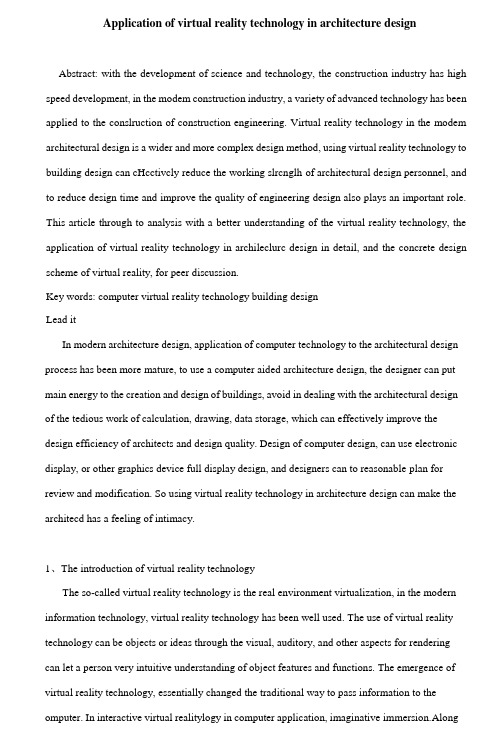
the 1993 Hubble Space Telescope (HST) Repair mission team using VR training Computer generated scene depicting the HST capture and EVA repair mission for mission planning虚拟现实的研究目的1.计算仿真为解决一些传统方法无法解决的问题提供了新途径、新方法。

我的梦想是当飞行员的英语作文初一全文共3篇示例,供读者参考篇1My Dream of Becoming a PilotEver since I was a little kid, I can remember being amazed whenever I saw an airplane soaring high up in the sky. I would gaze up in awe, wondering what it must be like to be the pilot up there, effortlessly cruising among the clouds. As I've grown older, that childhood sense of wonder has only intensified into a deep passion and an unshakable dream – I want to become a pilot.To me, being a pilot represents the ultimate combination of freedom, adventure, and responsibility. Just imagine having the entire sky as your workplace, with ever-changing scenery unfolding beneath you with every flight. One day you could be cruising over the rolling hills and peaks of the mighty Himalayas, the next day taking in the sparkling blue waters and pristine beaches of the Caribbean. The world would literally be at your fingertips from the cockpit.But being a pilot is about so much more than just traversing the globe and enjoying beautiful views. It's a highly skilledprofession that demands intense focus, quick decision-making abilities, and a tremendous amount of training and responsibility. As the pilot, you alone are accountable for safely transporting hundreds of passengers and crew to their destinations. Every take-off, flight, and landing requires precise calculations and strict adherence to procedures to ensure everyone's safety. That level of importance and high stakes is both daunting and incredibly alluring to me.I've always been the type of person who thrives under pressure and loves being challenged. In fact, it's what initially drew me to seriously consider this dream career path. I vividly remember when I was about 8 years old, my parents took me to a flight museum where you could practice in real flight simulators. While the other kids were just laughing and pulling levers haphazardly, I was completely locked in, meticulously going through all the checklists and procedures, relishing the chance to feel like I was in the pilot's seat. The flight instructor working with us that day even commented that I seemed to have a real knack and focus for it. From that moment on, I was hooked.In the years since, I've actively pursued opportunities to learn more about aviation and what it truly means to be a pilot.I've read countless books and articles, attended aviation camps, and even managed to go up in a small single-engine plane with a family friend who is a pilot. Each new experience has only reaffirmed my passion and strengthened my resolve to turn this dream into a reality.One of the aspects of being a pilot that appeals most to me is the opportunity to constantly be learning. With theever-evolving technology in modern aircraft and navigation systems, pilots must remain students for life, always adapting their skillset to master new advances. The idea of being a true lifelong learner in a field that is so dynamic and cutting-edge is incredibly exciting to me. I've always been an eager student who loves diving deep into complex topics and getting to the bottom of how things work. I can't think of a better application for my insatiable curiosity than aviation.In addition to my enthusiasm for the intellectual challenges, I'm also drawn to the pilot profession because of the unique combination of teamwork and individual responsibility it entails. As a pilot, you are the ultimate authority and decision maker for every flight. All eyes are on you to demonstrate poise under pressure and make split-second decisions that carry tremendous consequences. At the same time, you must be an expertcommunicator and collaborator, working seamlessly with your co-pilot, air traffic control teams, and ground crews to ensure complete coordination and safety at all times. It's about being a confident leader who can also function as part of a highly cohesive team working towards a unified goal. I believe my ability to wear multiple hats and transition between individual篇2My Dream to Become a PilotEver since I was a little kid, I've had this intense fascination with airplanes and flying. Whenever I would hear the roar of a jet engine overhead, I would run outside, gaze up at the sky, and dream about what it must feel like to soar through the clouds at hundreds of miles per hour. Some kids wanted to be firefighters or pro athletes when they grew up, but not me – I only had eyes for the skies.I can still vividly remember my first time going to the airport and watching all the planes take off and land. I was in complete awe of these mammoth metal birds gracefully defying gravity. As I stood there with my face pressed up against the glass, I made a promise to myself that one day, I would be the one in the cockpit, commandeering one of those awesome aircraft.That first plane ride further cemented my obsession. Even though I was just a young boy, I soaked in every single detail like a sponge. The awesome power of the engines screaming to life. The thrill of hurtling down the runway at over 100 mph before rotating and climbing up into the sky. The sweeping views of the cities and landscapes below as we cruised at altitude. Every part of it was pure magic to me.From that point on, I became a virtual encyclopedia of aviation knowledge. I read every book I could find on airplanes and flight. I drove my poor parents crazy with my constant barrage of questions about the physics of how wings generate lift or the different roles of the pilot, co-pilot, and other crew members. Aviation was my singular obsession in life.In school, I focused intently on the STEM subjects – science, technology, engineering, and math – as those would give me the strongest foundation for a future career in aviation. I joined aviation-themed clubs and went to as many air shows and pilot meet-and-greets as I could con my parents into taking me. My bedroom walls were plastered with posters of famous aircraft from history. If it involved flying machines in any way, shape or form, I was all over it like a kid in a candy store.As I reached my teenage years, that passion only intensified. While my peers were getting into music, sports, or video games, I was pouring all my time and energy into flight simulation software and games. I became an expert virtual pilot, able to operate every type of aircraft from small Cessnas to gigantic airliners to modern fighter jets. Those sims didn't just satisfy my hunger to fly – they made me downright ravenous for the real thing. I started doing everything I could to make my dream a reality.That's when my parents put their foot down and tried to temper my expectations, saying that becoming an airline or military pilot was statistically improbable and I should look into other, more realistic career paths. But their attempts to pour coldwater on my ambitions only fanned the flames further. I remained stubbornly, almost obsessively, dedicated to making it as a real-life pilot and would accept no alternative.So with my goal firmly cemented in my mind, I buckled down even harder on my studies. I exercised daily to ensure I would meet the physical fitness requirements. I joined the Civil Air Patrol teen program to start getting actual flight experience under my belt. And when I wasn't doing all that, I was workingpart-time jobs to start saving up for the astronomical costs of flight school tuition and certifications.Now, as I wrap up middle school and look ahead to high school, that pilot dream burns brighter than ever before. I know the path ahead won't be easy – in fact, it will probably be one of the most challenging and demanding journeys I'll ever undertake. But I've been laser-focused on this prize since I was able to talk, and I'm committed to doing whatever it takes to defy the odds and make it a reality.To me, being a pilot isn't just about the glamour or getting to travel the world for a living. It represents the culmination of a lifelong journey of tenacity, determination, and an unbreakable will to achieve what many people told me was impossible. It means following my heart with a singular, burning passion that can never be extinguished. Nothing is going to stand in my way.With hard work, sacrifice, grit and maybe a little luck thrown in, one day soon I'll be the one that little kids at the airport look up at with awe and wonder. One day, I'll get to experience that indescribable thrill and freedom of climbing up into the clouds, leaving the earth far behind as I take to the open skies at the controls of a beautiful, powerful machine of human ingenuity.And when that day finally comes, I know it will have all been worth it to make my wildest childhood dream a reality.So wish me luck, friends and family! I have a long, difficult road of training and perseverance ahead. But one thing is for certain – just like those篇3My Dream of Becoming a PilotEver since I was a little kid, I have been fascinated by airplanes and the idea of soaring through the vast sky. Whenever I heard the roar of a jet engine or saw a plane gliding gracefully overhead, I would gaze up in awe, wondering what it would be like to be the one in the cockpit, controlling that magnificent machine. As I grew older, my fascination only intensified, and my dream of becoming a pilot became an unwavering goal that I aspire to achieve.To me, being a pilot represents the epitome of freedom and adventure. Imagine being able to traverse continents in a matter of hours, soaring above the clouds and witnessing breathtaking landscapes that most people can only dream of seeing. The thought of navigating through the boundless skies, defyinggravity, and exploring the world from a bird's eye view is exhilarating beyond measure.However, becoming a pilot is not merely about the thrill of flying; it is a profession that demands utmost dedication, discipline, and responsibility. Pilots are entrusted with the lives of countless passengers, and their decisions can have profound consequences. This weight of responsibility is something I am prepared to shoulder, as I deeply respect the gravity of the role and the trust placed in pilots by the public.From a young age, I have been fascinated by the intricate workings of aircraft and the principles of aerodynamics. I would spend hours reading books and watching documentaries, eagerly absorbing every bit of information I could find about flight mechanics, navigation systems, and aircraft operations. The more I learned, the more I became convinced that this was the path I was meant to follow.Aside from the technical aspects, I am also drawn to the sense of camaraderie and teamwork that exists among pilots and flight crews. The idea of being part of a well-oiled team, working together seamlessly to ensure the safe and efficient operation of a flight, fills me with a sense of pride and belonging. I relish the opportunity to collaborate with other highly skilled professionals,communicating clearly and effectively to overcome challenges and achieve our shared goals.Furthermore, the life of a pilot promises a constant stream of new experiences and adventures. Each flight is a unique journey, offering the chance to witness stunning sunrises and sunsets, navigate through diverse weather conditions, and explore new destinations. The prospect of constantly learning and adapting to different situations is truly invigorating, and I am eager to embrace the challenges that come with this dynamic profession.Of course, the road to becoming a pilot is not an easy one. It requires years of rigorous training, countless hours of study, and unwavering commitment. From obtaining the necessary licenses and certifications to mastering complex systems and procedures, the journey is filled with obstacles that must be overcome through perseverance and determination. However, I am ready to face these challenges head-on, fueled by my passion for aviation and an unshakable belief in my ability to succeed.As I stand on the precipice of my high school years, my dream of becoming a pilot burns brighter than ever. I am fully committed to dedicating myself to this pursuit, working tirelessly to acquire the knowledge and skills necessary to excel in this field. Whether it's through extracurricular activities, internships,or any other opportunities that present themselves, I will seize every chance to immerse myself in the world of aviation and gain invaluable experience.In the years ahead, I envision myself soaring through the skies, confidently guiding a magnificent aircraft to its destination.I picture myself in the cockpit, meticulously going throughpre-flight checks, communicating seamlessly with air traffic control, and making split-second decisions that ensure the safety and comfort of my passengers. It is a vision that fills me with a sense of purpose and pride, and one that I am determined to turn into reality.。

写穿越机的作文400字英文回答:In the realm of the skies, where wind dances and adrenaline surges, there exists a marvel of engineering that defies gravity and pushes the boundaries of human ingenuity—the FPV drone. FPV, an acronym for First Person View, refers to the exhilarating experience of piloting a drone from the cockpit of a virtual reality headset, granting the pilot an immersive, eagle-eye perspective of the world below.These sleek and agile aerial machines are meticulously crafted with lightweight carbon fiber frames and powerful brushless motors, propelling them through the air with astonishing speed and precision. Equipped with high-definition cameras and advanced flight controllers, FPV drones empower pilots to navigate intricate environments, execute mind-boggling maneuvers, and capture breathtaking aerial footage.The allure of FPV racing lies in the adrenaline-pumping thrill of piloting these miniature speedsters through challenging obstacle courses at breakneck speeds. Racers don their headsets, immersing themselves in a virtual cockpit that transports them into the heart of the action, where every turn, dip, and acceleration becomes a visceral experience.Safety is paramount in the world of FPV drone racing. Pilots adhere to strict protocols before each flight, ensuring that their drones are in optimal condition andthat the designated airspace is clear of obstacles. Spectator zones are carefully cordoned off, allowing enthusiasts to witness the high-octane spectacle from a safe distance.FPV drones have also found their niche in the creative industry. Aerial cinematographers harness the versatility and maneuverability of these machines to capture stunning footage for films, documentaries, and commercials. With their ability to soar over landscapes, navigate tightspaces, and provide unique aerial perspectives, FPV drones have revolutionized the art of visual storytelling.In the future, FPV drones hold immense potential for innovation and technological advancements. Engineers are continually pushing the boundaries of performance, exploring new materials, propulsion systems, and flight control algorithms. The integration of artificial intelligence and autonomous flight capabilities promises to further enhance the capabilities of these aerial marvels.中文回答:翱翔于广阔天际,的风中,伴随着疾风劲舞和肾上腺素飙升,有一种来自工程学领域的奇迹,它无畏重力,挑战着人类智慧的极限——穿越机。

飞机玻璃化座舱发展历程英文回答:The development of glass cockpits in aircraft has undergone significant changes over the years. Initially, aircraft cockpits were equipped with analog instruments and gauges, which provided limited information to the pilots. However, with advancements in technology, the concept of glass cockpits emerged.Glass cockpits, also known as "glass panel" or "all-glass" cockpits, refer to the use of electronic displays instead of traditional analog instruments. These displays are made up of multiple screens that provide pilots with a comprehensive view of the aircraft's systems and flight parameters. The screens are typically made of durable and lightweight glass materials, such as acrylic or polycarbonate.One of the key benefits of glass cockpits is theimproved situational awareness they offer to pilots. The electronic displays can present a wide range of information, including flight instruments, navigation data, engine performance, weather conditions, and traffic information. This allows pilots to quickly and accurately assess the aircraft's status and make informed decisions.Another advantage of glass cockpits is the reduction in pilot workload. The integration of various systems into a single display simplifies the cockpit layout and reducesthe need for manual calculations and cross-referencing.This not only enhances safety but also allows pilots to focus more on flying the aircraft.Furthermore, glass cockpits have opened upopportunities for advanced features and functionalities.For example, synthetic vision systems (SVS) can be incorporated into the displays to provide pilots with a virtual view of the outside world, even in low visibility conditions. This enhances situational awareness and helps pilots navigate safely.In addition, glass cockpits have facilitated the implementation of automation in aircraft systems. With the integration of advanced avionics, autopilot systems, and flight management systems, pilots can rely on automationfor various tasks, such as navigation and aircraft control. However, it is important for pilots to maintain theirskills and be able to manually operate the aircraft in case of system failures or abnormal situations.Overall, the development of glass cockpits has revolutionized the aviation industry by providing pilots with enhanced situational awareness, reduced workload, and advanced features. As technology continues to advance, we can expect further improvements in glass cockpit systems, making flying safer and more efficient.中文回答:飞机玻璃化座舱的发展经历了多年的重大变革。

Single-Chip USB to UART BridgeCP2101Single-Chip USB to UART Data Transfer-Integrated USB Transceiver; No External Resistors Required-Integrated Clock; No External Crystal Required -Integrated 512-Byte EEPROM for Vendor ID, Product ID, Serial Number, Power Descriptor, Release Number and Product Description Strings -On-Chip Power-On Reset Circuit-On-Chip Voltage Regulator: 3.3 V OutputUSB Function Controller-USB Specification 2.0 Compliant; Full Speed (12 Mbps)-USB suspend states supported via SUSPEND pinsAsynchronous Serial Data BUS (UART)-All Handshaking and Modem Interface Signals -Data Formats Supported:•Data Bits: 8•Stop Bits: 1•Parity: Odd, Even, No Parity -Baud Rates: 300 bps to 921.6 kbps-512 Byte Receive Buffer; 512 Byte Transmit Buffer -Hardware or X-On / X-Off Handshaking Supported -Event Character SupportVirtual COM Port Device Drivers-Works with Existing COM Port PC Applications -Royalty-Free Distribution License -Windows 98/2000/XP -MAC OS-9-MAC OS-X -Windows CE*-Linux 2.40 and greater* (Contact factory for availability)Example Applications-Upgrade of RS-232 Legacy Devices to USB -Cellular Phone USB Interface Cable -PDA USB Interface Cable -USB to RS-232 Serial Adapter Supply Voltage-Self-powered: 3.0 to 3.6 V-USB Bus Powered: 4.0 to 5.25 V Package-28-pin MLP (5 x 5 mm)Temperature Range: -40 to +85 °CCP2101Table of Contents1.System Overview (4)2.Absolute Maximum Ratings (4)Table 2.1. Absolute Maximum Ratings (4)3.Global DC Electrical Characteristics (5)Table 3.1. Global DC Electrical Characteristics (5)Table 3.2. UART and Suspend I/O DC Electrical Characteristics (5)4.Pinout and Package Definitions (6)Table 4.1. Pin Definitions for the CP2101 (6)Figure 4.1. MLP-28 Pinout Diagram (Top View) (7)Figure 4.2. MLP-28 Package Drawing (8)Table 4.2. MLP-28 Package Dimensions (8)Figure 4.3. Typical MLP-28 Landing Diagram (9)Figure 4.4. Typical MLP-28 Solder Mask (10)B Function Controller and Transceiver (11)Figure 5.1. Typical Connection Diagram (11)6.Asynchronous Serial Data Bus (UART) Interface (12)Table 6.1. Data Formats and Baud Rates (12)7.Internal EEPROM (12)Table 7.1. Default USB Configuration Data (12)8.Virtual Com Port Device Drivers (13)9.Voltage Regulator (14)Table 9.1. Voltage Regulator Electrical Specifications (14)Figure 9.1. Configuration 1: USB Bus-Powered (14)Figure 9.2. Configuration 2: USB Self-Powered (15)Figure 9.3. Configuration 3: USB Self-Powered, Regulator Bypassed (15)1.System OverviewThe CP2101 is a highly-integrated USB-to-UART Bridge Controller providing a simple solution for updating RS-232 designs to USB using a minimum of components and PCB space. The CP2101 includes a USB 2.0 full-speed function controller, USB transceiver, oscillator, EEPROM and asynchronous serial data bus (UART) with full modem control signals in a compact 5 x 5 mm MLP-28 package. No other external USB components are required.The on-chip EEPROM may be used to customize the USB Vendor ID, Product ID, Product Description String, Power Descriptor, Device Release Number and Device Serial Number as desired for OEM applications. The EEPROM is programmed on-board via the USB allowing the programming step to be easily integrated into the product manufacturing and testing process.Royalty-free Virtual COM Port (VCP) device drivers provided by Silicon Laboratories allow a CP2101-based product to appear as a COM port to PC applications. The CP2101 UART interface implements all RS-232 signals, including control and handshaking signals, so existing system firmware does not need to be modified. In many existing RS-232 designs, all that is required to update the design from RS-232 to USB is to replace the RS-232 level-translator with the CP2101.An evaluation kit for the CP2101 (Part Number: CP2101EK) is available. It includes a CP2101-based USB-to-UART/RS-232 evaluation board, a complete set of VCP device drivers, USB and RS-232 cables, and full documentation. Contact a Silicon Labs’ sales representatives or go to to order the CP2101 Evaluation Kit.2.Absolute Maximum RatingsTable 2.1. Absolute Maximum RatingsParameter Conditions Min Typ Max Units Ambient temperature under bias–55—125°C Storage Temperature–65—150°C Voltage on any I/O Pin or RST with respect to–0.3— 5.8V GNDVoltage on V DD with respect to GND–0.3— 4.2V Maximum Total current through V DD and GND——500mA——100mA Maximum output current sunk by RST or anyI/O pinNote: stresses above those listed under “Absolute Maximum Ratings” may cause permanent damage to the device. This is a stress rating only and functional operation of the devices at those or any other condi-tions above those indicated in the operation listings of this specification is not implied. Exposure to maxi-mum rating conditions for extended periods may affect device reliability.CP21013.Global DC Electrical CharacteristicsTable 3.1. Global DC Electrical CharacteristicsV DD = 2.7 to 3.6 V, –40 to +85 °C unless otherwise specifiedParameter Conditions Min Typ Max Units Supply Voltage 3.0 3.3 3.6V Supply Current V DD = 3.3 V—25—mA Supply Current in Suspend V DD = 3.3 V—325—µA Specified Operating Temperature Range–40—+85°CTable 3.2. UART and Suspend I/O DC Electrical CharacteristicsV DD = 2.7 to 3.6 V, -40 to +85 °C unless otherwise specifiedParameters Conditions Min Typ Max UNITSOutput High Voltage I OH = -3mAI OH = -10µAI OH = -10mAVDD-0.7VDD-0.1VDD-0.8VOutput Low Voltage I OL = 8.5mAI OL = 10µAI OL = 25mA 1.00.60.1VInput High Voltage 2.0V Input Low Voltage0.8V Input Leakage Current2550µACP21014.Pinout and Package DefinitionsTable 4.1. Pin Definitions for the CP2101Name Pin #Type DescriptionV DD6Power InPowerOut3.0–3.6 V Power Supply Voltage Input.3.3 V Voltage Regulator Output. See Section 9.GND3GroundRST9 D I/O Device Reset. Open-drain output of internal POR or V DD monitor. An external source can initiate a system reset by driving this pin low for at least 15 µs.REGIN7Power In 5 V Regulator Input. This pin is the input to the on-chip voltage regu-lator.VBUS8 D In VBUS Sense Input. This pin should be connected to the VBUS signal of a USB network. A 5 V signal on this pin indicates a USB network connection.D+4 D I/O USB D+D–5 D I/O USB D–TXD26 D Out Asynchronous data output (UART Transmit) RXD25 D In Asynchronous data input (UART Receive) CTS23* D In Clear To Send control input (active low)RTS24* D Out Ready to Send control output (active low)DSR27* D in Data Set Ready control input (active low)DTR28* D Out Data Terminal Ready control output (active low) DCD1* D In Data Carrier Detect control input (active low)RI2* D In Ring Indicator control input (active low)SUSPEND12* D Out This pin is driven high when the CP2101 enters the USB suspend state.SUSPEND11* D Out This pin is driven low when the CP2101 enters the USB suspend state.NC10, 13–22These pins should be left unconnected or tied to V DD. *Note: Pins can be left unconnected when not used.CP2101Figure 4.1. MLP-28 Pinout Diagram (Top View)CP2101Figure 4.2. MLP-28 Package DrawingTable 0.1. MLP-28 Package DimensionsMM MIN TYP MAX A 0.800.90 1.00A100.020.05A200.65 1.00A3—0.25—b 0.180.230.30D — 5.00—D2 2.90 3.15 3.35E — 5.00—E2 2.90 3.15 3.35e —0.5—L 0.450.550.65N —28—ND —7—NE —7—R 0.09——AA —0.435—BB —0.435—CC —0.18—DD—0.18—CP2101Figure 4.3. Typical MLP-28 Landing DiagramCP2101Figure 4.4. Typical MLP-28 Solder Mask11Rev. 1.5B Function Controller and TransceiverThe Universal Serial Bus function controller in the CP2101 is a USB 2.0 compliant full-speed device with integrated transceiver and on-chip matching and pull-up resistors. The USB function controller manages all data transfers between the USB and the UART as well as command requests generated by the USB host controller and commands for controlling the function of the UART.The USB Suspend and Resume signals are supported for power management of both the CP2101 device as well as external circuitry. The CP2101 will enter Suspend mode when Suspend signaling is detected on the bus. On entering Suspend mode, the CP2101 asserts the SUSPEND and SUSPEND signals. SUSPEND and SUSPEND are also asserted after a CP2101 reset until device configuration during USB Enumeration is completeThe CP2101 exits the Suspend mode when any of the following occur: (1) Resume signaling is detected or generated, (2) a USB Reset signal is detected, or (3) a device reset occurs. On exit of Suspend mode, the SUSPEND and SUSPEND signals are de-asserted.Both SUSPEND and SUSPEND temporarily float high during a CP2101 reset. If this behavior is undesirable, a strong pulldown (10 kΩ) can be used to ensure SUSPEND remains low during reset. See Figure 5.1 for other recommended options.Figure 5.1. Typical Connection DiagramRev. 1.5126.Asynchronous Serial Data Bus (UART) InterfaceThe CP2101 UART interface consists of the TX (transmit) and RX (receive) data signals as well as the RTS, CTS, DSR, DTR, DCD and RI control signals. The UART supports RTS/CTS, DSR/DTR and X-On/X-Off handshaking.The UART is programmable to support a variety of data formats and baud rates. The data format and baud rate programmed into the UART is set during COM port configuration on the PC. The data formats and baud rates available are listed in Table 6.1.7.Internal EEPROMThe CP2101 includes an internal EEPROM that may be used to customize the USB Vendor ID, Product ID, Product Description String, Power Descriptor, Device Release Number and Device Serial Number as desired for OEM applications. Customization of the USB configuration data is optional. If the EEPROM is not programmed with OEM data, the default configuration data shown in Table 7.1 is used. However, a unique serial number is required for OEM applications in which it is possible for multiple CP2101-based devices to be connected to the same PC.The internal EEPROM is programmed via the USB. This allows the OEM's USB configuration data and serial number to be written to the CP2101 on-board during the manufacturing and testing process. A stand-alone utility for programming the internal EEPROM is available from Silicon Laboratories. A library of routines provided in the form of a Windows ® DLL is also available. This library can be used to integrate the EEPROM programming step into custom software used by the OEM to streamline testing and serial number management during manufacturing. The EEPROM has a typical endurance of 100,000 write cycles with a data retention of 100 years.Table 6.1. Data Formats and Baud RatesData Bits 8Stop Bits 1Parity Type None, Even, OddBaud Rates300, 600, 1200, 1800, 2400, 4800, 7200, 9600, 14400, 19200, 28800, 38400, 56000, 57600, 115200, 128000, 230400, 460800, 921600Table 7.1. Default USB Configuration DataName Value Vendor ID 10C4h Product IDEA60h Power Descriptor (Attributes)80hPower Descriptor (Max. Power)32h Release Number 0100hSerial Number0001 (63 characters maximum)Product Description String“CP2101 USB to UART Bridge Controller” (126 characters maximum)13Rev. 1.58.Virtual Com Port Device DriversThe CP2101 Virtual COM Port (VCP) device drivers allow a CP2101-based device to appear to the PC's application software as an additional COM port (in addition to any existing hardware COM ports). Application software running on the PC accesses the CP2101-based device as it would access a standard hardware COM port. However, actual data transfer between the PC and the CP2101 device is performed over the USB. Therefore, existing COM port applications may be used to transfer data via the USB to the CP2101-based device without modifying the application. Contact Silicon Laboratories for the latest list of supported operating systems.Note:The Silicon Laboratories VCP device drivers are required for device operation and are only distributed as part of the CP2101 Evaluation Kit (Part Number: CP2101EK). Contact any of Silicon Lab’s sales representatives or go to to order the CP2101 Evaluation Kit. The CP2101 drivers and programming utilities are subject to change without notice. Subscription to the website "Auto Email Alert" system for automatic notification of updates and the use of the "Product Update Registration" service is recommended.Rev. 1.5149.Voltage RegulatorThe CP2101 includes an on-chip 5-to-3 V voltage regulator. This allows the CP2101 to be configured as either a USB bus-powered device or a USB self-powered device. These configurations are shown in Figure 9.1 and Figure 9.2. When enabled, the 3 V voltage regulator output appears on the V DD pin and can be used to power external 3V devices. See Table 9.1 for the voltage regulator electrical characteristics.Alternatively, if 3 V power is supplied to the V DD pin, the CP2101 can function as a USB self-powered device with the voltage regulator disabled. For this configuration, it is recommended that the REGIN input be tied to the 3 V net to disable the voltage regulator. This configuration is shown in Figure 9.3.The USB max power and power attributes descriptor must match the device power usage and configuration. See application note “AN144: CP2101 Customization Guide” for information on how to customize USB descriptors for the CP2101.Note:It is recommended that additional decoupling capacitance (e.g., 0.1 µF in parallel with 1.0 µF) be provided on the REGIN input.Figure 9.1. Configuration 1: USB Bus-PoweredTable 9.1. Voltage Regulator Electrical Specifications–40 to +85 °C unless otherwise specifiedParameterConditionsMin Typ Max Units Input Voltage Range 4.0— 5.25V Output VoltageOutput Current = 1 to 100 mA*3.0 3.3 3.6V VBUS Detection Input Threshold 1.0 1.84.0V Bias Current—90TBDµA* The maximum regulator supply current is 100 mA.15Rev. 1.5Figure 9.2. Configuration 2: USB Self-PoweredFigure 9.3. Configuration 3: USB Self-Powered, Regulator BypassedRev. 1.516Document Change ListRevision 1.4 to Revision 1.5Updated Example System Diagram on page 1.Updated Table 3.1, “Global DC Electrical Characteristics,” on page 5.Added Table 3.2, “UART and Suspend I/O DC Electrical Characteristics,” on page 5 Added Table note to Table 4.1, “Pin Definitions for the CP2101,” on page 6 Added Figure 5.1. , "Typical Connection Diagram" on page 11Removed asterisk from the “Linux 2.40 and greater” bullet on page 117Rev. 1.5NotesRev. 1.518Contact InformationSilicon Laboratories Inc.4635 Boston Lane Austin, TX 78735Tel: 1+(512) 416-8500 Fax: 1+(512) 416-9669 Toll Free: 1+(877) 444-3032Email:********************** Internet: Silicon Laboratories and Silicon Labs are trademarks of Silicon Laboratories Inc.Other products or brandnames mentioned herein are trademarks or registered trademarks of their respective holdersThe information in this document is believed to be accurate in all respects at the time of publication but is subject to change without notice. Silicon Laboratories assumes no responsibility for errors and omissions, and disclaims responsibility for any consequences resulting from the use of information included herein. Additionally, Silicon Laboratories assumes no responsibility for the function-ing of undescribed features or parameters. Silicon Laboratories reserves the right to make changes without further notice. Silicon Laboratories makes no warranty, representation or guarantee regarding the suitability of its products for any particular purpose, nor does Silicon Laboratories assume any liability arising out of the application or use of any product or circuit, and specifically disclaims any and all liability, including without limitation consequential or incidental damages. Silicon Laboratories products are not designed, intended, or authorized for use in applications intended to support or sustain life, or for any other application in which the failure of the Silicon Laboratories product could create a situation where personal injury or death may occur. Should Buyer purchase or use Silicon Laboratories products for any such unintended or unauthorized application, Buyer shall indemnify and hold Silicon Laboratories harmless against all claims and damages.。

Electrifyingly fun to drive.The all-new Audi e-tron.With its combination of electric drive and a comfortable, sophisticated interior, the Audi e-tron creates a new sense of mobility. Whether parking, in the city or on long journeys, the Audi e-tron makes life easier for its driver in many situations. The full-size SUV combines sportiness and everyday practicality. Its two electric motors together with electric all-wheel drive provide for awesome performance and agile handling. The large high-voltage battery is the foundation for a sufficient range. In combination with a comprehensive range of charging options for home and on the move, you can enjoy fully electric driving without having to compromise.No limitThe new electric quattro drive permanently and fully variably regulates the ideal distribution of drive torques between the two axles. And within a split second. You'll particularly feel the benefits during off-road trips in the country. But evenwhen driving on the road, you can rely on the services of the quattro drive. Even inslippery complications such as when under-steering or oversteering occur and areaction would be required of you, the technology jumps for you.Unmistakably an SUVIn the side view, the shoulder line is an important design element. It runs from the front head-lamps over the flank to the rear lights and visually gives your Audi e-tron a low centre of gravity. The powerful D-pillars and underride protection are clear hallmarks of a SUV. The quattro blisters above the wheels indicate the electric four-wheel drive. The door sill area is clearly contoured and visualised with theblack inlays on the door attachment: this is where the battery is located.Matrix LED headlights with dynamic turn signalLED rear lights with dynamic indicatorsElectricity consumption combined in kWh/100 km: 22.2 – 26.1 (WLTP)CO₂ emissions combined in g/km: 0First class also in the second row Useful luggage carrierUp to three people can enjoy the spaciousness of the Audi e-tron in the rear.With the bench seat folded down, the maximum storage space is up to 1,725 l iters.Thanks to its luxuriant storage volume and folded seats, the maximum load capacity is more than twice as large. Comfortable: the tailgate canoptionally be opened by moving your foot. Get in andfeel goodLet the sun in with the panoramic glass roof.In particular, your passengers on rear seats willbenefit from the bright and friendly atmosphere.Breathe freely and fill up with fresh air: the optionalAir Quality package with ioniser and scent ensuresfirst-class air quality. The air quality sensor paysattention to your health: when harmful gases enterthe interior, it activates the recirculation system.Thanks to the very low overall noise level, you willsimply feel relaxed, as if life has slowed down.Virtual exterior mirrors. Standard feature for e-tron Sportback, optional for e-tron.Informed and secureAmple widthIn the Audi e-tron, you can rely on intelligent technologies and simply focus on traffic. Important information and notifications are available in the standard Audi virtual cockpit and the top infotainment system MMI navigation plus. Various driver assistance systems ensure your safety.With the Audi e-tron, you can negotiate distances from Hamburg to Düsseldorf without having to stop to charge. The high degree of recuperation, i.e. the recovery of braking energy, plays a considerable part in this. During much more than 90 percent of all decelerations, the Audi e-tron recharges itself via its e-machines. In combination with the electro hydraulically integrated brake control system, which we are the first manufacturer worldwide to use in an electrically driven passenger vehicle, the electric SUVexploits its maximum potential for recuperation.Charging made easyHome chargingPublic charging :Charge from 5% up to 80% in just 30 minutesThanks to a comprehensive range of digital services, you can keep an eye on charging-specific information at all times - in the Audi virtual cockpit of the Audi e-tron.The e-tron charging system compact has a charging capacity of up to 11 kW. On the control unit, the user can manually switch between 100 percent and 50 percent charging performance. This can be useful if various other electrical appliances are already in use at home.The Audi e-tron has the max. charging power of 150 kW and can hold up to 80% of the battery state-of-charge (SOC). As a result, the Audi e-tron only needs 30 minutes on a high-power charging (HPC) column for a typical charge of 5% to 80%. If, on the other hand, you want to fill the battery to 100% in order to be able to exploit the maximum range, thesophisticated battery management system only takes another 20 minutes.e-tron 55 quattro®e-tron Sportback 55 quattro® S-lineSolid Solid PearlMetallic MetallicBrilliant black Brilliant black Daytona grayCatalunya red Catalunya red Antigua blue Mythos black Floret silver Floret silver Navarra blue Navarra blue Galaxy blue Siam beige Plasma blue Siam beigeGlacier white Glacier whiteTyphoon grayManhattan gray Show your coloursGive your Audi e-tron a personal touch by choosing the paint colour. There are a total of ten tones to choose from. With accents in high-voltage orange, the Audi e-tron highlights its character as a purely electric vehicle. They can be found, for example, on the e-tron logo on the electric tailgate and on the orange calipers. The colour-highlighted wheel arch covers and door sills convey the message: theAudi e-tron is an off-road vehicle.Mythos blackIt's your chanceDive into the exciting world of electromobility with the Audi e-tron and help shape the future. Our first all-electric SUV is your sporty, everyday and safe companion for a new era. Make your Audi e-tron inspiringly unique with Audi wheels, selected inlays and coloured leather now!Allow wheelsUpholsteryin MilanoleatherAudiInlays21”21”OptionalOptional20”21”22”StandardStandarde-tron 55 quattro®e-tron Sportback 55 quattro® S-lineInlays in fine grain ash, natural volcano grayNatural walnut inlaysInlays in matt brushed aluminum, darkModelEngine typeMax. outputMax. torquePower transmissionDrive typeWeights / capacitiesEmpty weightPerm. Total weightPermissible roof load limit / Support load MileageTop SpeedAccelerationConsumptionFuel typeConsumption and emission values according to NEDCCombined power consumptionCombined CO2 emissionsElectric range according to WLTP *Real world figures may differ due to external factors. e-tron 55 quattro®Lithium-ion high-voltage battery powered,full electric300 kW664 Nmquattro® permanent all-wheel drive2,565 kg3,130 kg75/80 kg200 km / h0-100 km / h: 5.7sElectric22.2 – 26.1 kWh/100km0 g / km370 – 440 kme-tron Sportback 55 quattro® S-lineLithium-ion high-voltage battery powered,full electric300 kW664 Nmquattro® permanent all-wheel drive2,565 kg3,130 kg75/80 kg200 km / h0-100 km / h: 5.7sElectric21.6 – 25.8 kWh/100km0 g / km374 – 452 kmDimensions are for empty vehicle weight.Luggage capacity e-tron55 quattro® 660/1,725 l ; e-tron Sportback 55 quattro® S-line 615/1,665 l(second value is with the rear seat backrest folded down and the vehicle loaded up to roof height). Turning circle approx. 12.2 m.* Maximum headroom. ** Elbow room width. *** Shoulder room width. **** Vehicle height with roof aerial.***** Dimension based on vehicle equipped with virtual exterior mirrors. Vehicles with rear view exterior mirrors will increasevehicle width by 146 mm.Dimensions in mme-tron 55 Sportback quattro® S-lineDimensions in mme-tron 55 quattro®。

基于面向对象技术的飞行仿真研究张继夫;陈蕾;邓华;何昀【摘要】针对当前在飞行仿真建模领域遇到的模型重用性差,设计模式不统一,不能适应冠代军用飞行仿真需求的问题,尝试在工程实践中引入面向对象的设计方法,实现规范仿真建模过程的目的.通过研究面向对象技术在飞行仿真系统研制中的应用范围与应用方法,结合实际项目中飞机导航系统的仿真过程,使用面向对象技术对其进行分析与设计,并据此建立了仿真模型.利用这种方法建立的仿真模型清晰明了,易于理解,有效地增强了系统的可重用性和继承性,收到了良好的应用效果,证明了将面向对象技术应用于飞行仿真领域是可行的.【期刊名称】《计算机技术与发展》【年(卷),期】2010(020)007【总页数】5页(P211-215)【关键词】面向对象技术;面向对象仿真;飞行仿真;导航【作者】张继夫;陈蕾;邓华;何昀【作者单位】空军航空大学军事仿真技术研究所,吉林长春130022;空军航空大学军事仿真技术研究所,吉林长春130022;空军航空大学计算机教研室,吉林长春130022;空军航空大学军事仿真技术研究所,吉林长春130022【正文语种】中文【中图分类】TP391.90 引言随着现代军用飞机生产与制造技术的飞速发展,现在装备的及即将入役的三代及三代以上的军用飞机,都是集成化程度很高的高技术平台[1],具有非常复杂的飞控系统、火控设备、航电系统等,因此飞行器系统的高复杂度对飞行仿真提出了越来越高的要求。
同样原因,针对更加复杂的多任务的飞行仿真目标,如单机训练、多机交互式仿真、基于网络的仿真互联等等[2,3],也对飞行仿真提出了更加多样的需求,这使得在针对具体目标而进行的飞行仿真建模过程,依旧是一种需要消耗巨大精力的工作过程[4~6]。
正是由于上述原因,设想提出一种重用性更强、继承性更好、功能更完善的飞行仿真系统及其合理的、封装性好的软件框架,对适应飞行仿真的需求、改变现有开发模式是非常有益的。

Virtual Reality on a WIM: Interactive Worlds in Miniature Richard Stoakley, Matthew J. Conway, Randy PauschThe University of VirginiaDepartment of Computer ScienceCharlottesville, V A 22903{rws2v | conway | pausch}@(804) 982-2200KEYWORDSvirtual reality, three-dimensional interaction, two-handed interaction, information visualizationABSTRACTThis paper explores a user interface technique which aug-ments an immersive head tracked display with a hand-held miniature copy of the virtual environment. We call this interface technique the Worlds in Miniature (WIM) meta-phor. By establishing a direct relationship between life-size objects in the virtual world and miniature objects in the WIM, we can use the WIM as a tool for manipulating objects in the virtual environment.In addition to describing object manipulation, this paper explores ways in which Worlds in Miniature can act as a single unifying metaphor for such application independent interaction techniques as object selection, navigation, path planning, and visualization. The WIM metaphor naturally offers multiple points of view and multiple scales at which the user can operate, all without requiring explicit modes or commands.Informal user observation indicates that users adapt to the Worlds in Miniature metaphor quickly and that physical props are helpful in manipulating the WIM and other objects in the environment.INTRODUCTIONMany benefits have been claimed formally and informally for using immersive three dimensional displays. While vir-tual reality technology has the potential to give the user a better understanding of the space he or she inhabits, and can improve performance in some tasks [18], it can easily present a virtual world to the user that is just as confusing, limiting and ambiguous as the real world. We have grown accustomed to these real world constraints: things we can-not reach, things hidden from view, things beyond our sight and behind us, and things which appear close to each other because they line up along our current line of sight. Our vir-tual environments should address these constraints and with respect to these issues be “better” than the real world.In particular, we notice that many implementations of vir-tual environments only give the user one point of view (an all-encompassing, immersive view from within the head mounted display) and a single scale (1:1) at which to oper-ate. A single point of view prohibits the user from gaining a larger context of the environment, and the 1:1 scale in which the user operates puts most of the world out of the user’s immediate reach.To address these two concerns, we propose allowing a vir-tual reality user to hold in his or her hands a three-dimen-sional interactive model – a miniature copy of the life-size virtual world (figure 1). The objects in the model each cor-respond to a life-size object; the positions and orientations of these objects in the real world “shadow” those of their proxies in the miniature. Moving an object on the model moves an object in the real world and vice versa.This World In Miniature (WIM) gives the user another point of view from which to observe the scene, and the ability to change that point of view under direct manipulation as rap-idly as the user can turn the model in his or her hands.As an adjunct to the WIM, we have explored the advantages and disadvantages of grounding the user’s perception of the model with a physical prop; in this case, a clipboard.The rest of this paper discusses previous work in the realm of miniature worlds used for three dimensional interfaces, a description of our WIM implementation, the basic interac-tion techniques we have used to demonstrate the effective-ness of the WIM concept, and the importance of asymmetric two-handed interaction. We conclude with results from informal user observation of the WIM interface and a dis-cussion of future work.PREVIOUS WORKMany researchers have dealt with the open questions of three dimensional object manipulation and navigation in virtual environments. The World in Miniature metaphor draws on these previous experiences, and attempts to syn-thesize an intuitive, coherent model to help address these questions. Most previous work falls into two categories: (1) object manipulation and (2) navigation in virtual environ-ments.We use the term “navigation” to mean allowing the user to move in his or her virtual environment and helping the user maintain orientation while there.Previous Work in Object ManipulationWare’s Bat [23] interface demonstrates the use of a 6 degree-of-freedom (DOF) input device (a position and ori-entation tracker) to grab and place objects in a virtual envi-ronment. In this work, Ware used the bat to pick up and manipulate the virtual objects themselves, not miniature, proxy objects. Ware found that users easily understood the 1:1 mapping between translations and rotations on the input device and the object being manipulated. This study was a unimanual task and did not place the user’s hands in the same physical space as the graphics.In Sachs’s 3-Draw [20], we see two hands used asymmetri-cally in a three-dimensional drawing and designing task. In addition to this, Sachs used props for each of the user’s hands and found that relative motion between hands was better than a fixed single object and one free mover. 3-Draw was not implemented in an immersive, head-tracked envi-ronment and the system did not provide multiple, simulta-neous views. The input props controlled the point of view by rotating the object’s base plane.Hinkley’s [13] work with props exploited the asymmetric use of hands, which follows from work by Guiard [12]. This work showed how a prop in the non-dominant hand can be used to specify a coordinate system with gross ori-entation, while the user’s preferred hand can be used for fine grain positioning relative to that coordinate system. This work is also three dimensional but non-immersive and directly manipulates an object at 1:1 scale in a “fishtank”paradigm.3DM [2] was an immersive three dimensional drawing package, but provided only one point of view at a time and required the user to change scale or fly explicitly to manip-ulate objects which were currently out of arm’s reach. But-terworth states that users sometimes found the scaling disorienting.Schmandt’s [21] early explorations of Augmented Reality (AR) used a half-silvered mirror over a stationary drafting tablet in order to specify both a base plane and a slicing plane in computer generated VLSI models. He found this surface invaluable in constraining the user’s input to a plane. The scene was not immersive and the system only displayed one scale view at a time.Previous Work in NavigationDarken’s [7] discussion of navigating virtual environments enumerates many important techniques and compares their relative strengths and weaknesses. Several of the naviga-tion techniques presented were WIM-like maps, but were primarily two-dimensional in nature. Through the WIM interface, some of these techniques have been extended into the third dimension.Ware [24] explored the possibilities of holding the three-dimensional scene in hand for the purpose of quickly navi-gating the space. He found this scene in hand metaphor par-ticularly good for quickly viewing the bounding-cube edges of a scene. The scene in hand task was a unimanual opera-tion which employed ratcheting to perform large rotations. The work most closely resembling the WIM interface was Fisher’s map cube in virtual reality [9]. The NASA VIEW system used a three dimensional miniature map of the immersive world to help navigate. In addition, it used mul-tiple two dimensional viewports to jump from one place in the virtual environment to another. A user’s manipulation of the “map cube” was unimanual. A similar map-cube concept was referred to as the God’s-eye-view in the super cockpit project [11].Previous Work in Object SelectionMany researchers have explored methods for selecting objects in a virtual world. Common approaches include raycasting [10] [23] and selection cones [15]. Both of these techniques suffer from object occlusion and therefore need to be tied closely with some mechanism that can quickly establish different points of view.Put-That-There [3] used selection via a combination of pointing and naming (or description). Pointing in this two dimensional application is analogous to raycasting in vir-tual environments.SYSTEM DESCRIPTIONTo explore the benefits and limitations of the WIM meta-phor, we built a simple three dimensional modeling pack-age that could be used as a design tool for a traditional architecture design project called a Kit of Parts.We outfitted the user’s non-dominant hand with a clipboard attached to a Polhemus position sensor. In his or her other hand, the user holds a tennis ball in which we have installedtwo buttons and another Polhemus™ sensor. This button-ball was used as the selection and manipulation tool for all of our user observation and WIM development. The first button on the buttonball was used for selection of objects,and the second was left open for application-specified actions. Thus equipped, the user’s view from inside the HMD is exactly like that in any other immersive virtual environment, except that the user can raise the clipboard to view a miniature copy of the world in which he or she is standing and can lower the WIM graphics out of sight toremove them from his or her field of view (figure 2).The WIMgraphics attached to the clipboard are nothing more than a miniature copy of all the surrounding graphics in the immersive environment. Each of the objects in the WIM copy are tied to their counterparts in the immersive environment through pointers and vice versa at the point of WIM creation. In this way, when an object responds to a method call, the object has enough information to ensure that the same method gets called on its “shadow” object.Thus the user can manipulate the objects in the WIM and the objects in the world will follow (video figure 1 - The WIM Interface). The environment itself (in miniature)becomes its own widget for manipulating objects in the environment [5].Software and EquipmentThe Kit of Parts modeler was implemented using the Alice Rapid Prototyping System [6] running the simulation on a Sun Microsystems Sparc 10™ and rendering on a Silicon Graphics Onyx Reality Engine 2™. Typical rendering rates were about 25 frames per second (FPS ), while simulation rates were typically 6FPS . A Virtual Research Flight Hel-met™ was used for the display and was tracked with a Pol-hemus Isotrak magnetic tracker. The buttonball and clipboard each carried a Polhemus tracker sensor for posi-tion and orientation information.INTERACTION TECHNIQUES USING THE WIMIn this section, we discuss basic application independent WIM -based interaction techniques we have built using the Alice Rapid Prototyping System [6].Quickly Changing the POVBeing able to see objects from many different angles allows us to quickly remove or reduce occlusion and improves the sense of the three-dimensional space it occupies [22].Because the WIM is a hand-held model, the user can quickly establish different points of view by rotating the WIM in both hands. Note that this form of “WIM fly-by” can often give the user all the information that he or she needs with-out destroying the point of view established in the larger,immersive point of view. We believe that this interaction technique can establish a new viewpoint more quickly and with less cognitive burden than a technique that requires an explicit “flight” command and management of the flight path.Object Selection: Overcoming Range and OcclusionIf the virtual, immersive environment is very large, there will be objects that are out of physical arm’s reach. If the user must touch an object to select it, the user would have to employ a separate flying mechanism, which means mov-ing the camera; a sometimes disorienting or otherwise inap-propriate approach. Armed with a World In Miniature ,the user now has the choice of selecting objects either by point-ing to the object itself (as before) or by pointing to its proxy on the WIM . By turning the model in his or her hands, the user can even view and pick objects that are obscured by his or her current line of sight from the immersive camera viewpoint. The WIM provides a second (often “bird’s eye”)point of view from which to examine the scene.Object ManipulationOnce objects are selected, the WIM allows us to manipulate those objects at either the scale offered by the WIM or the one-to-one scale offered by the immersive environment. If the scale of the WIM is smaller than that of the immersive world, manipulating objects on the WIM necessarily gives the user far-reaching coarse-grained control of objects.The WIM can also display objects at a greater than one-to-one scale, implementing a three dimensional magnifying glass of sorts. This gives the user very fine grain control of objects through the WIM at the expense of range. Though we have not implemented zooming in our current system,we clearly see the need for allowing the user to get more detail on the WIM or to zoom out to view more context. We are currently pursuing this avenue of research.We speculate that because the WIM is clearly a model attached to the user’s hand, it is seen as something separate from the rest of the immersive environment. The WIM therefore naturally offers two different scales to the user without requiring explicit modes or commands.An Example: Hanging a PicturePutting these ideas together, we can consider an example task: hanging a picture on a wall. This task is typical of abroad class of two-person tasks in which the proximity required to manipulate an object interferes with the desire to see those effects in a larger context. With a WIM, a single user can stand at a comfortable distance to view the picture in context, while at the same time reaching into the WIM to manipulate it.Of course, the user could choose to use the WIM the other way around: fly close to the wall to stand next to the pic-ture, then use the WIM to view the entire room in miniature to determine if the picture is straight. Examining relative strengths and weaknesses of each of these approaches is an area of further study.Mixing Scales and OperationsViewing, selection, and manipulation are independent oper-ations. Because the WIM gives the user another scale at which to operate, the user can choose the most appropriate scale for any given subtask, and even switch scales in the middle to suit the requirements of the task. For example: the user can reach into the WIM to select a distant object (taking advantage of the greater than 1:1 scale of the WIM), and then reach out to the immersive world to move the WIM-selected object at a distance in 1:1: scale [23] [15] all the while viewing the scene in the WIM.RotationOur current implementation allows users to rotate objects, through ratcheting (repeated grabbing, rotating and releas-ing) [25] and is therefore more awkward than a rotation done with just the fingers [15]. Interestingly, some users found it just as effective to grab the object and to counter-rotate the entire WIM.In our current implementation, rotation is gridded to 30 degree increments, primarily to assist in aligning rectilinear objects [15]. We found that if the rotation grid is too course (greater than about 45 degrees), some people assume that they cannot rotate at all and if set to 15 degrees or less, users report that rotation behaves as if it had no gridded increments at all.Navigation: Flight with a WIMTo make the view travel through the immersive environ-ment, the most common user interface technique in virtual environments is probably “flying.” If the WIM includes some representation of the user as an object in the scene, the user can simply reach into the WIM and “pick himself up” to change his location in the environment. This raises the question of when to update the immersive world as objects in the WIM are manipulated. We enumerate three possibilities.Updating after Manipulation:immediate / post-mortem / batchWhen changes are made on the WIM, we usually move the real object and the proxy object simultaneously, something we refer to as immediate update. Under some conditions, immediate update is either not desirable (due to visual clut-ter or occlusion) or impossible (the complexity of the object prevents changes to it from being updated in real time). In these situations, we use post-mortem update,where the immersive environment updates only after the user is finished with the WIM interaction and has released the proxy.A good special case of post-mortem update is the case of moving the user’s viewpoint. We find that immediate update of the camera while the user is manipulating the camera proxy is highly disorienting, so instead we wait until the user has stopped moving the camera, and then use a smooth slow in / slow out animation [16] to move the camera to its new position. This animated movement helps maintain visual continuity [15].Another useful form of update delay is batch update. Here, the user makes several changes to the WIM and then issues an explicit command (e.g. pressing the second button on the buttonball) to cause the immersive environment to com-mit to the current layout of the WIM. This is useful for two reasons. First, before the user commits his or her changes, the user has two independent views of the environment (the “as-is” picture in the immersive world and the “proposed”picture in the WIM). Secondly, it might be the case that moving one object at a time might leave the simulation in an inconsistent state, and so “batching” the changes like this gives the user a transaction-like commit operation on the changes to objects in the scene (with the possibility of supporting rollback or revert operations if the changes seem undesirable halfway through the operation). VISUALIZATIONThe Worlds in Miniature metaphor supports several kinds of displays and interaction techniques that fall loosely under the heading of visualization. These techniques exploit the WIM’s ability to provide a different view of the immersive data with improved context. It would seem that the WIM is good for visualization for all the same reasons that a map is good for visualization:Spatially locating and orienting the user:the WIM can pro-vide an indicator showing where the user is and which way he or she is facing relative to the rest of the environment. Path planning: with a WIM we can easily plan a future camera path in three dimensions to prepare for an object fly-by. The user can even preview the camera motion before committing him or herself to the change in the larger, immersive viewpoint.History: if the user leaves a trail behind as he or she travels from place to place, the WIM can be used like a regular 2D map to see the trail in its entirety. Dropping a trail of crumbs is not as useful if you cannot see the trail in context. Measuring distances:the WIM can be configured to display distances between distant (or very closely spaced) points that are difficult to reach at the immersive one-to-one scale. The WIM also provides a convenient tool for measuring areas and volumes.Viewing alternate representations:the immersive environ-ment may be dense with spatially co-located data (i.e. topo-logical contours, ore deposits, fault lines). The user candisplay data like this on the WIM, showing an alternate view of the immersive space in context. The improved context can also facilitate the observation of more implicit relation-ships in a space (i.e. symmetry, primary axis) and can dis-play data not shown in the immersive scene (circulation patterns, wiring and plumbing paths). Here, the WIM acts more like a three dimensional version of Beir’s “magic lenses” [1] or one of Fitzmaurice’s “active maps” [10]. Three Dimensional Design: the WIM, being a small three dimensional model, serves the same functions that architec-tural models have traditionally served.MULTIPLE WIMSUntil now, we have considered only a single instantiation of a WIM in a virtual environment, but clearly there might be a reason to have more than one such miniature active at a time. Multiple WIM s could be used to display:•widely separated regions of the same environment •several completely different environments•worlds at different scales•the same world displayed at different points in time This last option allows the user to do a side by side compar-ison of several design ideas (video figure 2 –Multiple WIM s). A logical extension of this notion is that these snap-shots can act as jump points to different spaces or times, much the same way hypertext systems sometimes have thumbnail pictures of previously visited documents [14]. Selecting a WIM would cause the immersive environment to change to that particular world [9].Multiple WIM s enable users to multiplex their attention much the same way Window Managers allow this in 2D. These multiple views into the virtual world, allow the user to visually compare different scales and/or different loca-tions [8].MANIPULATING THE WIMThrough the exploration of the previous interfaces, several issues arose concerning the interface between the human and the WIM tool.The Importance of PropsOne of our early implementations of the WIM work did not use physical props; the user grasped at the WIM graphics as he or she would any other graphical object in the scene. As long the user continued the grasping gesture, the WIM fol-lowed the position and orientation of the user’s hand and when released, it would remain hovering in space wherever it was dropped. While this was sufficient for many tasks, we found that rotating the WIM without the benefit of haptic feedback was extremely difficult. Invariably, users would contort themselves into uncomfortable positions rather than let go of the WIM to grab it again by another, more comfort-able corner.After Sachs [20], we decided to use physical props to assist the user’s manipulation of the WIM itself. To represent the WIM, we chose an ordinary clipboard to which we attached a Polhemus 6 DOF tracker for the user’s non-dominant hand. For the user’s preferred hand, we used a tennis ball with a Polhemus tracker and two buttons (figure 3). Props: The ClipboardThis prop allows the user to rotate the WIM using a two-handed technique that passes the clipboard quickly from one hand to the other and back when the rotation of the WIM is greater than can be done comfortably with one hand. Interestingly, some users hold the clipboard from under-neath, rotating the clipboard deftly with one hand. Both of these techniques are hard to imagine doing in the absence of haptic feedback provided by a physical prop.Props: The ButtonballBefore we settled on the buttonball as our primary pointing device, we experimented with a pen interface to the WIM. This technique is most appropriate for manipulation of objects when they are constrained to a plane [21] (the base plane being the default). When manipulation of objects in three dimensions is called for, a pen on the surface of the clipboard does not appear to be expressive enough to cap-ture object rotation well.Two Handed InteractionOur implementation of the WIM metaphor takes advantage of several previously published results in the field of motor behavior that have not been fully exploited in a head tracked virtual environment. The most important of these results state that a human’s dominant (preferred) hand makes its motions relative to the coordinate system speci-fied by the non-dominant hand, and the preferred hand’s motion is generally at a finer grain [12]. In our case, the non-dominant hand establishes a coordinate system with the clipboard and the dominant hand performs fine grained picking and manipulation operations.While the dominant hand may be occupied with a pointing device of some kind, it is still sufficiently free to help the other hand spin the WIMquickly when necessary.Shape of PropsLike all real world artifacts, the shape of the props and the users’ experience suggest things about the usage of the props [17]. For example, the shape of the clipboard says something to users about its preferred orientation. The cur-sor’s physical prop is spherical, indicating that it has no preferred orientation, and in fact it does not matter how the cursor is wielded since rotation is relative to the plane spec-ified with the non-dominant hand, which holds the clip-board.The clipboard also provides a surface that the user can bear down on when necessary. This is similar to the way an artist might rest his or her hand on a paint palette or a guitarist might rest a finger on the guitar body.PROBLEMS WITH PHYSICAL PROPSThe use of the clipboard as a prop presents some problems of its own.FatigueHolding a physical clipboard, even a relatively light one, can cause users to fatigue rather quickly. To overcome this problem, we created a simple clutching mechanism that allows the user to alternately attach and detach the WIM from the physical prop with the press of a button. When detached, the WIM “floats” in the air, permitting the user to set the prop down (video figure 3 – Prop Clutching). This clutching mechanism extended well to multiple WIM s: when the user toggles the clutch, the closest WIM snaps to the user’s clipboard. Toggling the clutch again disengages the current WIM and allows the user to pick up another WIM. Another technique for relieving arm stress is to have the user sit at a physical table on which the clipboard could be set. Users can also rest their arms on the table while manip-ulating the model. The presence of the table clearly pre-sents a mobility problem for the user because it prevents the user from moving or walking in the virtual environ-ment, and so may not be ideal for all applications. Limitations of Solid ObjectsIn our experience, one of the first things a user of the WIM is likely to try is to hold the WIM close to his or her face in order to get a closer, more dynamic look at the world. Users quickly discover that this is an easy, efficient way to estab-lish many different points of view from inside the minia-ture. Unfortunately, many times the physical prop itself gets in the way, preventing the user from putting the tracker in the appropriate position to get a useful viewpoint. Fortu-nately, the ability to disengage the WIM, leaving it in space without the clipboard helps alleviate this problem. INFORMAL OBSERVATIONWe observed ten people using the WIM. Some had previous experience with virtually reality, and some had three dimensional design experience (e.g. architecture students). Users were given a simple architectural modeler and asked to design an office space. We proceeded with a rapid “observe, evaluate, revise” methodology to learn about the Worlds in Miniature interface.The user was given a miniature copy of the room he or she was standing in, and a series of common furniture pieces on a shelf at the side of the WIM (figure 4). The user was then asked to design an office space by positioning the furniture in the room.In many ways, this design task replicates the traditional architectural design project known as a Kit of Parts. The furniture pieces (half-height walls, shelves, tables and table corner pieces) represent the kit of manipulable objects. Moving the traditional kit of parts project into virtual real-ity was particularly appealing for several reasons:•It constrains the space in which the user can work.•Since users are designing a life-size space, clearly see-ing that space at 1:1 scale is helpful.•The WIM succinctly replaces the plans, elevations and models typically associated with this type of design project.The WIM that we used was a 1/4” scale version of the immersive world, with a snap spacing of 1/8” (0.5 scale feet). In addition to the translation snap, rotation was con-strained to be about the Z axis in increments of 30 degrees.User ReactionsWe observed users in order to see how viable a solution the WIM interface was to several types of tasks. While it was not our intention for the study to produce concrete num-bers, we were after what Brooks refers to as interesting “Observations” [14]. We hoped to gain some sense of:1 )How quickly do users take to the WIM metaphor?2 )How do users like the weight and maneuverability ofthe physical clipboard?3 )Do users like clutching? Do they take to it easily?4 )How do users feel about moving themselves via thecamera proxy?None of the users expressed problems establishing the map-。

模拟飞行十操作方法(Simulated flight ten operation method)Knee panel (display / hide) SHIFT+F10Mission target (next) KTask pointer (on / off) SHIFT+UMouse visual adjustment (on) SPACEBARSwitch to cockpit view, F9Switch to pilot view, F10Switch to model global view F11Go to satellite view, F12Throttle (throttle) (flow) F1Throttle (throttle) (decrease) F2Throttle (throttle) (increase) F3Throttle (throttle) (full flow) F4Engine (start / stop) CTRL+EBrakes (application / release). (PERIOD)Head up (horizontal lift) Down arrowHead down (level down) Up arrowAileron (left) Left arrowAileron (to the right) Right arrowEnd flight ESC keyAnalog flight 10----FSX keyboard command button (with keyboard control), I also play this way, I hope to help you ~!The 1. emulator command pauses P or Break2. full screen mode ALT +Enter3. display menus or hide ALT4. shows or hides the ATC menu? ACCENT or SCROLL LOCK?5. displays or hides the (Kneeboard) Shift + F106. sound switch Q7. resets the current flight CTRL +; (semicolon)8. save the flight; (semicolon)9. exit flight simulator CTRL+ C10. immediately exit the flight simulator CTRL + Break11. joystick (disable / use) CTRL + K12. global coordinates / frame rate Shift + Z13. select the first 114. select second 215. select third 316. select fourth 417. select time compression R18. airdrop supplies SHIFT + D19. request tanker SHIFT + F20. displays or hides aircraft tags CTRL + SHIFT + L21. shows or hides flight skills CTRL + SHIFT + X22. increase selection =23. slowly increase, select SHIFT + =24. slow down, select SHIFT+ -25. reduce selection -26. capture screenshot V27. mobile bridges (jetways) CTRL + J28. plane control plane command aileron left tilt digital keypad 429. aileron right tilt digital keyboard 6Aileron left trim CTRL + numeric keypad 430. aileron right trim CTRL + numeric keypad 631. vertical tail right yaw digital keyboard Enter32. vertical tail left deviation digital keyboard 033. vertical tail right trim CTRL+ digital keyboard Enter34. vertical tail left trim CTRL + numeric keyboard 035. aileron or vertical fin center numeric keypad 536. horizontal elevator down digital keyboard 837. level elevator up digital keyboard 238. trim down trim digital keyboard 739. lift up trim digital keyboard 140. flaps fully retracted F541. flaps slowly retracted F642. flaps slowly extended F743. flaps fully extended F844. stretch out / hold out the spoiler45. pre spoiler SHIFT + /46. engine control command select engine E+ engine number47. select all engines E+1+2+3+448., cut off the throttle valve F1 (throttle valve is the throttle)49. recoil (turbofan / jet engine) F2 hold and hold50. reduce the throttle F251. increase the throttle valve F352. throttle maximum F453. propeller low speed CTRL + F154. propellers increase speed CTRL + F55. propeller high speed CTRL + F456., oil and gas mixed idle, cut off CTRL+ SHIFT +F157. oil and gas mixed fast CTRL+ SHIFT +F2 oil58., oil and gas mixed with oil, CTRL+, SHIFT, +F359., oil and gas mixing completely rich oil, CTRL+, SHIFT, +F460. magneto select M61. main battery or alternator SHIFT+M62. jet engine start button J63. helicopter clutch switch SHIFT+ (DOT).64. helicopter rotor regulator switch SHIFT+, (comma)65. helicopter rotor brake switch SHIFT+B66. increase selection (e.g. magnification angle) = = equal to numberSixty-sevenSlow increase, select SHIFT+ =68. slow down, select SHIFT + -69. reduce selection -70. general aviation aircraft control command (parking brake set) CTRL +.71. control the tail wheel, turn left and right SHIFT+P, then 1 and 272. brake switch (DOT).73. left brake digital keyboard +74. right brake numeric keypad -75. retractable landing gear G76. wheel lock switch SHIFT+G77. manually put down landing gear CTRL+ GThe 78. child panel displays or hides SHIFT + (1 to 9)Switch 79. | smoke system80. hood flaps slowly open CTRL+ SHIFT + V81. engine hood transliteration slow down CTRL+ SHIFT + C82. request towing aircraft CTRL+ SHIFT + Y83. release the traction rope SHIFT + Y84. lights command all lights switch L85. frequency flashing switch O86. panel light switch SHIFT +L87. landing light switch CTRL +L88. landing lights bias left CTRL+ SHIFT + numeric keyboard 489. the landing light is biased to the right CTRL+ SHIFT + numeric keyboard 690. the landing light is biased on the CTRL+ SHIFT + numeric keyboard 891. the landing light is centered CTRL+ SHIFT + numeric keyboard 592. radio control command VOR 1 switch CTRL+193.VOR 2 switch CTRL +294.MKR switch CTRL + 395.DME switch CTRL + 496.ADF switch CTRL+ 597. alternate frequency X98.NAV radio select NThe 99.OBS indicator selects SHIFT +V100.ADF selects CTRL+ SHIFT +A101.DME selects F102. radar transceiver select T103. auto drive command master switch Z104. flight guidance switch CTRL +F105. yaw damper switch CTRL+D106. height hold switch CTRL, +Z107. height knob, select CTRL +SHIFT+Z108. heading hold switch CTRL + H109. course knob select CTRL+ SHIFT +H110. airspeed retaining switch CTRL + R111. Maher number hold switch CTR+M112. auto throttle SHIFT+R113. automatic throttle engagement (TOGA) CTRL+SHIFT +G114.NAV1 hold switch CTRL +N115. near in mode switch CTRL +A116. reverse approach (BC) mode switch CTRL, +B117. positioning beacon hold switch CTRL +O118. attitude hold switch CTRL +TThe 119. meter course indicator reset command D120. altimeter reset B121. the pitot tube heating switch SHIFT +H122. angle control command flat cockpit W123. align panel view (Snap, to, Panel, View) SHIFT + numeric keyboard 0124. check out the next S125. check the last SHIFT +S126. see the next view in the category A127. see the last view in the category SHIFT +A128. check the previous view link (toggle) CTRL +S129. check (default scaling), backspace 130., BACKSPACE 131. close the selected window]132. virtual cockpit F9133.2D cockpit F10134. side view F11135. overlooking angle F12136. window (select window at the upper level)137. magnification =138. reduce -139. next window CTRL + TABOne hundred and forty141. on the previous window, CTRL + SHIFT + TAB142. task command compass / pointer switch U143. compass target next K144. a SHIFT +K on the compass target145. multiplayer control chat windows show 146. or hide CTRL + SHIFT+J147. chat window (activate) ENTER148. transmit / receive control SHIFTT149. follow other players CTRL + SHIFT + F150. start transmit voice CAPS LOCK151. stop transferring voice ^ CAPS LOCK152. start transmitting voice to all players SHIFT + CAPS LOCK153. stop transferring voice to all players ^SHIFT + CPAS LOCK154.SLEW (rotary) mode control key 155. rotary analog switch Y156. heading north / altitude layer CTRL + spacebar157. freeze all movement numbers on keyboard 5One hundred and fifty-eightFreeze all vertical motion F2159. left turn digital keyboard 1160. left tilt digital keyboard 7161. right tilt digital keyboard 9 162. head up 9163. quick header F5164. bow your head F7 or 0165. quick bow F8。


Network Working Group E. Bell Request for Comments: 2674 3Com Corp. Category: Standards Track A. Smith Extreme Networks P. Langille Newbridge Networks A. Rijhsinghani Cabletron Systems K. McCloghrie cisco Systems August 1999 Definitions of Managed Objects for Bridges with TrafficClasses, Multicast Filtering and Virtual LAN ExtensionsStatus of this MemoThis document specifies an Internet standards track protocol for theInternet community, and requests discussion and suggestions forimprovements. Please refer to the current edition of the "InternetOfficial Protocol Standards" (STD 1) for the standardization stateand status of this protocol. Distribution of this memo is unlimited. Copyright NoticeCopyright (C) The Internet Society (1999). All Rights Reserved. AbstractThis memo defines a portion of the Management Information Base (MIB)for use with network management protocols in TCP/IP based internets.In particular, it defines two MIB modules for managing the newcapabilities of MAC bridges defined by the IEEE 802.1D-1998 MACBridges and the IEEE 802.1Q-1998 Virtual LAN (VLAN) standards forbridging between Local Area Network (LAN) segments. One MIB moduledefines objects for managing the ’Traffic Classes’ and ’EnhancedMulticast Filtering’ components of IEEE 802.1D-1998. The other MIBmodule defines objects for managing IEEE 802.1Q VLANs.Provisions are made for support of transparent bridging. Provisionsare also made so that these objects apply to bridges connected bysubnetworks other than LAN segments. This memo also includes several MIB modules in a manner that is compliant to the SMIv2 [V2SMI].This memo supplements RFC 1493 [BRIDGEMIB] and (to a lesser extent)RFC 1525 [SBRIDGEMIB].Bell, et al. Standards Track [Page 1]Table of Contents1 The SNMP Management Framework (3)2 Overview (4)2.1 Scope (4)3 Structure of MIBs (5)3.1 Structure of Extended Bridge MIB module (5)3.1.1 Relationship to IEEE 802.1D-1998 Manageable Objects (6)3.1.2 Relationship to IEEE 802.1Q Manageable Objects (8)3.1.3 The dot1dExtBase Group (8)3.1.4 The dot1dPriority Group (9)3.1.5 The dot1dGarp Group (9)3.1.6 The dot1dGmrp Group (9)3.1.7 The dot1dTpHCPortTable (9)3.1.8 The dot1dTpPortOverflowTable (9)3.2 Structure of Virtual Bridge MIB module (9)3.2.1 Relationship to IEEE 802.1Q Manageable Objects (9)3.2.2 The dot1qBase Group (13)3.2.3 The dot1qTp Group (13)3.2.4 The dot1qStatic Group (13)3.2.5 The dot1qVlan Group (13)3.3 Textual Conventions (13)3.4 Relationship to Other MIBs (14)3.4.1 Relationship to the ’system’ group (14)3.4.2 Relation to Interfaces MIB (14)3.4.2.1 Layering Model (15)3.4.2.2 ifStackTable (16)3.4.2.3 ifRcvAddressTable (16)3.4.3 Relation to Original Bridge MIB (16)3.4.3.1 The dot1dBase Group (16)3.4.3.2 The dot1dStp Group (17)3.4.3.3 The dot1dTp Group (17)3.4.3.4 The dot1dStatic Group (17)3.4.3.5 Additions to the Original Bridge MIB (18)4 Definitions for Extended Bridge MIB (18)5 Definitions for Virtual Bridge MIB (39)6 Acknowledgments (80)7 Security Considerations (80)8 References (81)9 Authors’ Addresses (84)10 Intellectual Property (85)11 Full Copyright Statement (86)Bell, et al. Standards Track [Page 2]1. The SNMP Management FrameworkThe SNMP Management Framework presently consists of five majorcomponents:o An overall architecture, described in an Architecture forDescribing SNMP Management Frameworks [ARCH].o Mechanisms for describing and naming objects and events for thepurpose of management. The first version of this Structure ofManagement Information (SMI) is called SMIv1 and described in STD 16, RFC 1155 [V1SMI], STD 16, RFC 1212 [V1CONCISE] and RFC 1215[V1TRAPS]. The second version, called SMIv2, is described in STD 58, RFC 2578 [V2SMI], STD 58, RFC 2579 [V2TC] and STD 58, RFC2580 [V2CONFORM].o Message protocols for transferring management information. Thefirst version of the SNMP message protocol is called SNMPv1 anddescribed in STD 15, RFC 1157 [V1PROTO]. A second version of the SNMP message protocol, which is not an Internet standards trackprotocol, is called SNMPv2c and described in RFC 1901[V2COMMUNITY] and RFC 1906 [V2TRANS]. The third version of themessage protocol is called SNMPv3 and described in RFC 1906[V2TRANS], Message Processing and Dispatching [V3MPC] and User-based Security Model [V3USM].o Protocol operations for accessing management information. Thefirst set of protocol operations and associated PDU formats isdescribed in STD 15, RFC 1157 [V1PROTO]. A second set ofprotocol operations and associated PDU formats is described inRFC 1905 [V2PROTO].o A set of fundamental applications described in SNMPv3Applications [V3APPS] and the view-based access control mechanism described in View-based Access Control Model [V3VACM].Managed objects are accessed via a virtual information store, termed the Management Information Base or MIB. Objects in the MIB aredefined using the mechanisms defined in the SMI.This memo specifies a MIB module that is compliant to the SMIv2. AMIB conforming to the SMIv1 can be produced through the appropriatetranslations. The resulting translated MIB must be semanticallyequivalent, except where objects or events are omitted because notranslation is possible (use of Counter64). Some machine readableinformation in SMIv2 will be converted into textual descriptions in Bell, et al. Standards Track [Page 3]SMIv1 during the translation process. However, this loss of machine readable information is not considered to change the semantics of the MIB.2. OverviewA common device present in many networks is the Bridge. This device is used to connect Local Area Network segments below the networklayer. These devices are often known as ’layer 2 switches’.There are two major modes defined for this bridging: Source-Route and transparent. Source-Route bridging is described by IEEE 802.5[802.5]. and is not discussed further in this document.The transparent method of bridging is defined by IEEE 802.1D-1998[802.1D] which is an update to the original IEEE 802.1D specification [802.1D-ORIG]. Managed objects for that original specification oftransparent bridging were defined in RFC 1493 [BRIDGEMIB].The original IEEE 802.1D is augmented by IEEE 802.1Q-1998 [802.1Q] to provide support for ’virtual bridged LANs’ where a single bridgedphysical LAN network may be used to support multiple logical bridged LANs, each of which offers a service approximately the same as thatdefined by IEEE 802.1D. Such virtual LANs (VLANs) are an integralfeature of switched LAN networks. A VLAN can be viewed as a group of end-stations on multiple LAN segments and can communicate as if they were on a single LAN. IEEE 802.1Q defines port-based Virtual LANswhere membership is determined by the bridge port on which dataframes are received. This memo defines the objects needed for themanagement of port-based VLANs in bridge entities.This memo defines those objects needed for the management of abridging entity operating in the transparent mode, as well as someobjects applicable to all types of bridges. Managed objects forSource-Route bridging are defined in RFC 1525 [SRBRIDGEMIB].2.1. ScopeThis MIB includes a comprehensive set of managed objects whichattempts to match the set defined in IEEE 802.1D and IEEE 802.1Q.However, to be consistent with the spirit of the SNMP Framework, asubjective judgement was made to omit the objects from thosestandards most ’costly’ to implement in an agent and least’essential’ for fault and configuration management. The omissionsare described in section 3 below.Bell, et al. Standards Track [Page 4]Historical note:The original bridge MIB [BRIDGEMIB] used the following principles for determining inclusion of an object in the BRIDGE-MIB module:(1) Start with a small set of essential objects and add only asfurther objects are needed.(2) Require objects be essential for either fault or configuration management.(3) Consider evidence of current use and/or utility.(4) Limit the total of objects.(5) Exclude objects which are simply derivable from others inthis or other MIBs.(6) Avoid causing critical sections to be heavily instrumented.The guideline that was followed is one counter per criticalsection per layer.3. Structure of MIBsThis document defines additional objects, on top of those existing in the original BRIDGE-MIB module defined in [BRIDGEMIB]: that MIBmodule is to be maintained unchanged for backwards compatibility.Section 3.4.3 of the present document contains some recommendationsregarding usage of objects in the original bridge MIB by devicesimplementing the enhancements defined here.Two MIB modules are defined here:(1) Managed objects for an extended bridge MIB module P-BRIDGE-MIB for the traffic class and multicast filtering enhancementsdefined by IEEE 802.1D-1998 [802.1D].(2) Managed objects for a virtual bridge MIB module Q-BRIDGE-MIBfor the Virtual LAN bridging enhancements defined by IEEE802.1Q-1998 [802.1Q].3.1. Structure of Extended Bridge MIB moduleObjects in this MIB are arranged into groups. Each group isorganized as a set of related objects. The overall structure andassignment of objects to their groups is shown below.Bell, et al. Standards Track [Page 5]3.1.1. Relationship to IEEE 802.1D-1998 Manageable ObjectsThis section contains a cross-reference to the objects defined inIEEE 802.1D-1998 [802.1D]. It also details those objects that arenot considered necessary in this MIB module.Some objects defined by IEEE 802.1D-1998 have been included in thevirtual bridge MIB module rather than this one: entries indot1qTpGroupTable, dot1qForwardAllTable anddot1qForwardUnregisteredTable are required for virtual bridged LANswith additional indexing (e.g. per-VLAN, per-FDB) and so are notdefined here. Instead, devices which do not implement virtualbridged LANs but do implement the Extended Forwarding Servicesdefined by IEEE 802.1D (i.e. dynamic learning of multicast groupaddresses and group service requirements in the filtering database)should implement these tables with a fixed value for dot1qFdbId (the value 1 is recommended) or dot1qVlanIndex (the value 1 isrecommended). Devices which support Extended Filtering Servicesshould support dot1qTpGroupTable, dot1qForwardAllTable anddot1qForwardUnregisteredTable.Bell, et al. Standards Track [Page 6]Extended Bridge MIB Name IEEE 802.1D-1998 Namedot1dExtBase Bridgedot1dDeviceCapabilitiesdot1dExtendedFilteringServicesdot1dTrafficClassesdot1dTrafficClassesEnableddot1dGmrpStatus .ApplicantAdministrativeControl dot1dPrioritydot1dPortPriorityTabledot1dPortDefaultUserPriority .UserPrioritydot1dPortNumTrafficClassesdot1dUserPriorityRegenTable .UserPriorityRegenerationTabledot1dUserPrioritydot1dRegenUserPrioritydot1dTrafficClassTable .TrafficClassTabledot1dTrafficClassPrioritydot1dTrafficClassdot1dPortOutboundAccessPriorityTable.OutboundAccessPriorityTabledot1dPortOutboundAccessPrioritydot1dGarpdot1dPortGarpTabledot1dPortGarpJoinTime .JoinTimedot1dPortGarpLeaveTime .LeaveTimedot1dPortGarpLeaveAllTime .LeaveAllTimedot1dGmrpdot1dPortGmrpTabledot1dPortGmrpStatus .ApplicantAdministrativeControldot1dPortGmrpFailedRegistrations .FailedRegistrationsdot1dPortGmrpLastPduOrigin .OriginatorOfLastPDUdot1dTpdot1dTpHCPortTabledot1dTpHCPortInFrames .BridgePort.FramesReceiveddot1dTpHCPortOutFrames .ForwardOutBounddot1dTpHCPortInDiscards .DiscardInbounddot1dTpPortOverflowTabledot1dTpPortInOverflowFrames .BridgePort.FramesReceiveddot1dTpPortOutOverflowFrames .ForwardOutBounddot1dTpPortInOverflowDiscards .DiscardInboundBell, et al. Standards Track [Page 7]The following IEEE 802.1D-1998 management objects have not beenincluded in the Bridge MIB for the indicated reasons.IEEE 802.1D-1998 Object DispositionBridge.StateValue not considered usefulBridge.ApplicantAdministrativeControlnot provided per-attribute(e.g. per-VLAN, per-Group).Only per-{device,port,application} control is provided in this MIB.3.1.2. Relationship to IEEE 802.1Q Manageable ObjectsThis section contains section number cross-references to manageableobjects defined in IEEE 802.1Q-1998 [802.1Q]. These objects havebeen included in this MIB as they provide a natural fit with the IEEE 802.1D objects with which they are co-located.Extended Bridge MIB Name IEEE 802.1Q-1998 Section and Name dot1dExtBase Bridgedot1dDeviceCapabilitiesdot1qStaticEntryIndividualPort 5.2 implementation optionsdot1qIVLCapabledot1qSVLCapabledot1qHybridCapabledot1qConfigurablePvidTagging 12.10.1.1 read bridge vlanconfigdot1dLocalVlanCapabledot1dPortCapabilitiesTabledot1dPortCapabilitiesdot1qDot1qTagging 5.2 implementation optionsdot1qConfigurableAcceptableFrameTypes5.2 implementation optionsdot1qIngressFiltering 5.2 implementation options3.1.3. The dot1dExtBase GroupThis group contains the objects which are applicable to all bridgesimplementing the traffic class and multicast filtering features ofIEEE 802.1D-1998 [802.1D]. It includes per-device configuration ofGARP and GMRP protocols. This group will be implemented by alldevices which implement the extensions defined in 802.1D-1998.Bell, et al. Standards Track [Page 8]3.1.4. The dot1dPriority GroupThis group contains the objects for configuring and reporting status of priority-based queuing mechanisms in a bridge. This includes per- port user_priority treatment, mapping of user_priority in frames into internal traffic classes and outbound user_priority andaccess_priority.3.1.5. The dot1dGarp GroupThis group contains the objects for configuring and reporting onoperation of the Generic Attribute Registration Protocol (GARP).3.1.6. The dot1dGmrp GroupThis group contains the objects for configuring and reporting onoperation of the GARP Multicast Registration Protocol (GMRP).3.1.7. The dot1dTpHCPortTableThis table extends the dot1dTp group from the original bridge MIB[BRIDGEMIB] and contains the objects for reporting port bridgingstatistics for high capacity network interfaces.3.1.8. The dot1dTpPortOverflowTableThis table extends the dot1dTp group from the original bridge MIB[BRIDGEMIB] and contains the objects for reporting the upper bits of port bridging statistics for high capacity network interfaces forwhen 32-bit counters are inadequate.3.2. Structure of Virtual Bridge MIB moduleObjects in this MIB are arranged into groups. Each group isorganized as a set of related objects. The overall structure andassignment of objects to their groups is shown below. Somemanageable objects defined in the original bridge MIB [BRIDGEMIB]need to be indexed differently when they are used in a VLAN bridging environment: these objects are, therefore, effectively duplicated by new objects with different indexing which are defined in the Virtual Bridge MIB.3.2.1. Relationship to IEEE 802.1Q Manageable ObjectsThis section contains section-number cross-references to manageableobjects defined in clause 12 of IEEE 802.1Q-1998 [802.1Q]. It alsodetails those objects that are not considered necessary in this MIBmodule.Bell, et al. Standards Track [Page 9]Note: unlike IEEE 802.1D-1998, IEEE 802.1Q-1998 [802.1Q] did notdefine exact syntax for a set of managed objects: the followingcross-references indicate the section numbering of the descriptionsof management operations from clause 12 in the latter document.Virtual Bridge MIB object IEEE 802.1Q-1998 Referencedot1qBasedot1qVlanVersionNumber 12.10.1.1 read bridge vlan config dot1qMaxVlanId 12.10.1.1 read bridge vlan config dot1qMaxSupportedVlans 12.10.1.1 read bridge vlan config dot1qNumVlansdot1qGvrpStatus 12.9.2.1/2 read/set garpapplicant controlsdot1qTpdot1qFdbTabledot1qFdbIddot1qFdbDynamicCount 12.7.1.1.3 read filtering d/basedot1qTpFdbTabledot1qTpFdbAddressdot1qTpFdbPortdot1qTpFdbStatusdot1qTpGroupTable 12.7.7.1 read filtering entrydot1qTpGroupAddressdot1qTpGroupEgressPortsdot1qTpGroupLearntdot1qForwardAllTable 12.7.7.1 read filtering entrydot1qForwardAllPortsdot1qForwardAllStaticPortsdot1qForwardAllForbiddenPortsdot1qForwardUnregisteredTable 12.7.7.1 read filtering entrydot1qForwardUnregisteredPortsdot1qForwardUnregisteredStaticPortsdot1qForwardUnregisteredForbiddenPortsdot1qStaticdot1qStaticUnicastTable 12.7.7.1 create/delete/readfiltering entry12.7.6.1 read permanent databasedot1qStaticUnicastAddressdot1qStaticUnicastReceivePortdot1qStaticUnicastAllowedToGoTodot1qStaticUnicastStatusdot1qStaticMulticastTable 12.7.7.1 create/delete/readfiltering entry12.7.6.1 read permanent databasedot1qStaticMulticastAddressdot1qStaticMulticastReceivePortdot1qStaticMulticastStaticEgressPortsBell, et al. Standards Track [Page 10]dot1qStaticMulticastForbiddenEgressPortsdot1qStaticMulticastStatusdot1qVlandot1qVlanNumDeletesdot1qVlanCurrentTable 12.10.2.1 read vlan configuration 12.10.3.5 read VID to FIDallocations12.10.3.6 read FID allocated toVID12.10.3.7 read VIDs allocated toFIDdot1qVlanTimeMarkdot1qVlanIndexdot1qVlanFdbIddot1qVlanCurrentEgressPortsdot1qVlanCurrentUntaggedPortsdot1qVlanStatusdot1qVlanCreationTimedot1qVlanStaticTable 12.7.7.1/2/3 create/delete/readfiltering entry12.7.6.1 read permanent database12.10.2.2 create vlan config12.10.2.3 delete vlan configdot1qVlanStaticName 12.4.1.3 set bridge namedot1qVlanStaticEgressPortsdot1qVlanForbiddenEgressPortsdot1qVlanStaticUntaggedPortsdot1qVlanStaticRowStatusdot1qNextFreeLocalVlanIndexdot1qPortVlanTable 12.10.1.1 read bridge vlanconfigurationdot1qPvid 12.10.1.2 configure PVID valuesdot1qPortAcceptableFrameTypes 12.10.1.3 configure acceptableframe types parameterdot1qPortIngressFiltering 12.10.1.4 configure ingressfiltering parametersdot1qPortGvrpStatus 12.9.2.2 read/set garp applicantcontrolsdot1qPortGvrpFailedRegistrationsdot1qPortGvrpLastPduOrigindot1qPortVlanStatisticsTable 12.6.1.1 read forwarding portcountersdot1qTpVlanPortInFramesdot1qTpVlanPortOutFramesdot1qTpVlanPortInDiscardsdot1qTpVlanPortInOverflowFramesdot1qTpVlanPortOutOverflowFramesdot1qTpVlanPortInOverflowDiscardsBell, et al. Standards Track [Page 11]dot1qPortVlanHCStatisticsTable 12.6.1.1 read forwarding portcountersdot1qTpVlanPortHCInFramesdot1qTpVlanPortHCOutFramesdot1qTpVlanPortHCInDiscardsdot1qLearningConstraintsTable 12.10.3.1/3/4 read/set/deletevlan learning constraints 12.10.3.2 read vlan learningconstraints for VIDdot1qConstraintVlandot1qConstraintSetdot1qConstraintTypedot1qConstraintStatusdot1qConstraintSetDefaultdot1qConstraintTypeDefaultThe following IEEE 802.1Q management objects have not been includedin the Bridge MIB for the indicated reasons.IEEE 802.1Q-1998 Operation Dispositionreset bridge (12.4.1.4) not considered usefulreset vlan bridge (12.10.1.5) not considered usefulread forwarding port counters (12.6.1.1)discard on error details not considered usefulread permanent database (12.7.6.1)permanent database size not considered usefulnumber of static filtering count rows inentries dot1qStaticUnicastTable +dot1qStaticMulticastTablenumber of static VLAN count rows inregistration entries dot1qVlanStaticTableread filtering entry range use GetNext operation.(12.7.7.4)read filtering database (12.7.1.1)filtering database size not considered usefulnumber of dynamic group address count rows applicable to each entries (12.7.1.3) FDB in dot1dTpGroupTableBell, et al. Standards Track [Page 12]read garp state (12.9.3.1) not considered usefulnotify vlan registration failure not considered useful(12.10.1.6)notify learning constraint violation(12.10.3.10) not considered useful3.2.2. The dot1qBase GroupThis mandatory group contains the objects which are applicable to all bridges implementing IEEE 802.1Q virtual LANs.3.2.3. The dot1qTp GroupThis group contains objects that control the operation and report the status of transparent bridging. This includes management of thedynamic Filtering Databases for both unicast and multicastforwarding. This group will be implemented by all bridges thatperform destination-address filtering.3.2.4. The dot1qStatic GroupThis group contains objects that control static configurationinformation for transparent bridging. This includes management ofthe static entries in the Filtering Databases for both unicast andmulticast forwarding.3.2.5. The dot1qVlan GroupThis group contains objects that control configuration and reportstatus of the Virtual LANs known to a bridge. This includesmanagement of the statically configured VLANs as well as reportingVLANs discovered by other means e.g. GVRP. It also controlsconfiguration and reports status of per-port objects relating toVLANs and reports traffic statistics. It also provides formanagement of the VLAN Learning Constraints.3.3. Textual ConventionsThe datatypes MacAddress, BridgeId, Timeout, EnabledStatus, PortList, VlanIndex and VlanId are used as textual conventions in thisdocument. These textual conventions have NO effect on either thesyntax nor the semantics of any managed object. Objects definedusing these conventions are always encoded by means of the rules that define their primitive type. Hence, no changes to the SMI or theSNMP are necessary to accommodate these textual conventions which are adopted merely for the convenience of readers.Bell, et al. Standards Track [Page 13]3.4. Relationship to Other MIBsAs described above, some IEEE 802.1D management objects have not been included in this MIB because they overlap with objects in other MIBs applicable to a bridge implementing this MIB. In particular, it isassumed that a bridge implementing this MIB will also implement (atleast) the ’system’ group defined in MIB-II [MIB2], the ’interfaces’ group defined in [INTERFACEMIB] and the original bridge MIB[BRIDGEMIB].3.4.1. Relationship to the ’system’ groupIn MIB-II, the ’system’ group is defined as being mandatory for allsystems such that each managed entity contains one instance of eachobject in the ’system’ group. Thus, those objects apply to theentity as a whole irrespective of whether the entity’s solefunctionality is bridging, or whether bridging is only a subset ofthe entity’s functionality.3.4.2. Relation to Interfaces MIBThe Interfaces Group MIB [INTERFACEMIB], requires that any MIB which is an adjunct of the Interfaces Group MIB, clarify specific areaswithin the Interfaces Group MIB. These areas were intentionally left vague in the Interfaces Group MIB to avoid over-constraining the MIB, thereby precluding management of certain media-types.The Interfaces Group MIB enumerates several areas which a media-specific MIB must clarify. Each of these areas is addressed in afollowing subsection. The implementor is referred to the Interfaces Group MIB in order to understand the general intent of these areas.In the Interfaces Group MIB, the ’interfaces’ group is defined asbeing mandatory for all systems and contains information on anentity’s interfaces, where each interface is thought of as beingattached to a ‘subnetwork’. (Note that this term is not to beconfused with ‘subnet’ which refers to an addressing partitioningscheme used in the Internet suite of protocols.) The term ’segment’ is used in this memo to refer to such a subnetwork, whether it be an Ethernet segment, a ’ring’, a WAN link, or even an X.25 virtualcircuit.Implicit in this Extended Bridge MIB is the notion of ports on abridge. Each of these ports is associated with one interface of the ’interfaces’ group (one row in ifTable) and, in most situations, each port is associated with a different interface. However, there aresituations in which multiple ports are associated with the sameBell, et al. Standards Track [Page 14]interface. An example of such a situation would be several portseach corresponding one-to-one with several X.25 virtual circuits but all on the same interface.Each port is uniquely identified by a port number. A port number has no mandatory relationship to an interface number, but in the simplecase a port number will have the same value as the correspondinginterface’s interface number. Port numbers are in the range(1..dot1dBaseNumPorts).Some entities perform other functionality as well as bridging through the sending and receiving of data on their interfaces. In suchsituations, only a subset of the data sent/received on an interfaceis within the domain of the entity’s bridging functionality. Thissubset is considered to be delineated according to a set ofprotocols, with some protocols being bridged, and other protocols not being bridged. For example, in an entity which exclusively performed bridging, all protocols would be considered as being bridged, whereas in an entity which performed IP routing on IP datagrams and onlybridged other protocols, only the non-IP data would be considered as being bridged. Thus, this Extended Bridge MIB (and in particular,its counters) is applicable only to that subset of the data on anentity’s interfaces which is sent/received for a protocol beingbridged. All such data is sent/received via the ports of the bridge.3.4.2.1. Layering ModelThis memo assumes the interpretation of the Interfaces Group to be in accordance with the Interfaces Group MIB [INTERFACEMIB] which states that the interfaces table (ifTable) contains information on themanaged resource’s interfaces and that each sub-layer below theinternetwork layer of a network interface is considered an interface. This document recommends that, within an entity, VLANs which areinstantiated as an entry in dot1qVlanCurrentTable by eithermanagement configuration through dot1qVlanStaticTable or by dynamicmeans (e.g. through GVRP), are NOT also represented by an entry inifTable.Where an entity contains higher-layer protocol entities e.g. IP-layer interfaces that transmit and receive traffic to/from a VLAN, theseshould be represented in the ifTable as interfaces of typepropVirtual(53). Protocol-specific types such as l3ipxvlan(137)should not be used here since there is no implication that the bridge will perform any protocol filtering before delivering up to thesevirtual interfaces.Bell, et al. Standards Track [Page 15]3.4.2.2. ifStackTableIn addition, the Interfaces Group MIB [INTERFACEMIB] defines a table ’ifStackTable’ for describing the relationship between logicalinterfaces within an entity. It is anticipated that implementorswill use this table to describe the binding of e.g. IP interfaces to physical ports, although the presence of VLANs makes therepresentation less than perfect for showing connectivity: theifStackTable cannot represent the full capability of the IEEE 802.1Q VLAN bridging standard since that makes a distinction between VLANbindings on ’ingress’ to and ’egress’ from a port: theserelationships may or may not be symmetrical whereas Interface MIBEvolution assumes a symmetrical binding for transmit and receive.This makes it necessary to define other manageable objects forconfiguring which ports are members of which VLANs.3.4.2.3. ifRcvAddressTableThis table contains all MAC addresses, unicast, multicast, andbroadcast, for which an interface will receive packets and forwardthem up to a higher layer entity for local consumption. Note thatthis does not include addresses for data-link layer control protocols such as Spanning-Tree, GMRP or GVRP. The format of the address,contained in ifRcvAddressAddress, is the same as for ifPhysAddress.This table does not include unicast or multicast addresses which are accepted for possible forwarding out some other port. This table is explicitly not intended to provide a bridge address filteringmechanism.3.4.3. Relation to Original Bridge MIBThis section defines how objects in the original bridge MIB module[BRIDGEMIB] should be represented for devices which implement theextensions: some of the old objects are less useful in such devicesbut must still be implemented for reasons of backwards compatibility. Note that formal conformance statements for that MIB module do notexist since it is defined in SMIv1.3.4.3.1. The dot1dBase GroupThis mandatory group contains the objects which are applicable to all types of bridges. Interpretation of this group is unchanged.Bell, et al. Standards Track [Page 16]。

风力发电用接触器C Ont a‘;(Qr,S I I Jsed i D}№W i,d Po¨er C.一ener al i Q.泰科电子推出适合风力发电应用的500A接触器叫II.ovAc L E V200接触器实现高可靠性的电力开关泰科电子面向国内外市场最新推出ⅪLO V A CLEV200接触器,这款产品最高可承受500A电流,专门用于制作风轮机的开关设备、变桨距和偏航驱动器以及发电机中典型的电力开关。
该接触器采用密封式结构,内部填充惰性气体,壳体采用环氧树脂密封,为内部提供了长期保护,可耐受近海多风车农场的严酷环境。
K I L O V A C L E V200接触器在长期不操作的情况下,其触点也不会被氧化或污染。
E V200接触器具有1个F or m X (SPs T—N O—D M)主触点,另外还有1个Form A(S Ps T.N O)辅助触点。
若在650C条件下采用400M C M导体,可承载320V、500A的持续直流电流。
采用其它导体可承载的额定电流将更高。
LE V200可切断320V、2000A的直流电流,触点电压范围为12V D C至900V D C。
L E V200系列适合垂直和侧边等各种位置的安装。
另外,由于接触器侧边安装的整体高度较低,因而非常适合用于狭小空间。
A m y D U X u D a n标准线圈的工作电压可为12V D C、24V D C或48V D C,泰科电子L E V200系列接触器的工作电压可为96V D C、115V A C或定制的直流电压。
线圈端子可选择为带状引线或10-32螺栓。
泰科电子的销售网络遍布全国,在全国各主要城市建立了销售服务网点,为中国用户提供部分标准产品的同时。
可帮助客户装配、测试、维修产品,及提供售前售后技术培训等,从而为广大中国客户提供贴心、稳定的服务。
—一N ovel l Z enw or ks A ppl i cat i on V i rt ual i zat i on解决方案’f№60l ul i or)of M ovel l Ze,,#or ks A ppl i(;at i o,V i daal i zaH o.提升桌面灵活性并降低管理成本N ovdl近日宣布推出N ovel l@Z EN w or ks@A ppl i c at i on V i m t al i z血o n解决方案,该方案可解决W i ndow s桌面应用程序兼容性问题,并易于使用。

LevelOneKVM-0211/KVM-0411KVM-0212/KVM-04122/4-Port PS/2 KVM SwitchUser ManualVer. 1.0.0-0711SafetyFCCThis equipment has been tested and found to comply with Part 15 of the FCC Rules. Operation is subject to the following two conditions:(1) This device may not cause harmful interference(2) This device must accept any interference received, including interference that may cause undesired operation.CEThis equipment is in compliance with the requirements of the following regulations: EN 55 022: CLASS BRoHSThis product is RoHS compliant.Table of Contents1.INTRODUCTION (1)1.1F EATURE OVERVIEW (1)1.2P ACKAGE C ONTENTS (2)2.HARDWARE INSTALLATION (3)1.1S TEP BY S TEP I NSTALLATION (3)2.2E ASY O PERATION (4)3.HOTKEY COMMAND TABLE (6)4.TECHNICAL SPECIFICATION (7)1. IntroductionLevelOne KVM-0211/KVM-0411/KVM-0212/KVM-0412 is 2/4-port Slim Desktop PS/2 KVM Switch with optional audio and microphone switching function in select models. The KVM switch allows users to access, control two (KVM-0211/0212) or four (KVM-0411/0412)PS/2-enabled computers from a single console. (Keyboard, Monitor, Mouse, and speaker set and microphone). It also offers user-programmable simultaneous/independent switching of PC channel and Audio/Mic channel for flexible multimedia application with KVM switching. For users who might need to use a hotkey preceding sequence other than scroll locks, LevelOne KVM switch also offers five alternatives keys for easy configuration. Setup is fast and easy; plugging cables into the appropriate ports is all that is entailed. There is no software require; no need to get involved into complex installation routines. LevelOne KVM Switch provides two convenient methods to bring the KVM focus to the target computer:a) By pressing one of the port selection switches located on the unit’s front panel.b) By entering the hotkey combinations from the keyboard.There is no better way to access your multiple computers than with LevelOne KVM switch. By allowing a single console to manage all of the computers, the KVM switch eliminates the expense of purchasing a separate keyboard, monitor and mouse for each one. Additionally, it saves the extra space and energy costs that additional consoles would require, and it eliminates the inconvenience and waste effort involved in constantly having to move around from one computer to another.NoteKVM-0212 and KVM-0412 are non-audio models without Audio andMicrophone support.1.1 Feature overviewz2-port/4-port Slim Desktop PS/2 KVM switch with Audio Support(KVM-0211/KVM-0411)z Share Speakers and Microphone between computers (KVM-0211/KVM-0411)z Computer selection via hotkeys or push buttonsz Auto-scan mode for PC monitoringz LED display for easy status monitoringz High VGA resolution supports up to 2048 x 15361.2 Package Contentsz KVM-0211/KVM-0411/KVM-0212/KVM-0412z KVM Cable Setz CD Manualz Quick Installation GuideCheck to make sure that all of the components are present and in good condition.If anything is missing, or was damaged in shipping, please contact your dealer immediately. Read this manual thoroughly and follow the installation and operation procedures carefully to prevent any damage to the KVM switch or to any other devices on the installation.Note2-Port PS/2 KVM Switch KVM-0211 and KVM-0212 contains with 2 cable setsin the package.4-Port PS/2 KVM Switch KVM-0411 and KVM-0412 contains with 4 cable setsin the package.2. Hardware InstallationThe default setting of the KVM-0211/KVM-0411/KVM-0212/KVM-0412is appropriate for most systems. The KVM Switch is a Plug-and-Play device for installation. In fact, user does not need to configure the KVM Switch before installation.For the first time installation of the KVM Switch, please follow the instructions below for setup sequence:1. Connect the shared keyboard, monitor and mouse (and optional speaker set andmicrophone) to the KVM Switch first, and then connect the computers.2. Power up your connected computersSince the KVM Switch receives power from the computer’s PS/2 interface, it is powered up when user connects the KVM Switch to a PC.Please see next section for detail installation.1.1 Step by Step InstallationTake the companion CD, KVM Cables and the KVM Switch out of the box and follow the steps below for installation.1. Make sure all the computers that are to be connected to the KVM Switch and theirperipherals are in powered-off state. If not, power them off before proceed with the following steps.2. Connect the shared PS/2 keyboard, PS/2 mouse, D-Sub monitor, speaker set andmicrophone to the KVM switch.3. Connect each of the computers to the KVM switch, using appropriate KVM & Audio/MICcables that companion with KVM switch in the package. Please note that the models KVM-0212 and KVM-0412 does not support audio switching function.4. Power up the connected computers one by one. After your computers are powered up,the keyboard and mouse will be recognized and now you can begin operating the KVM switch.2.2 Easy OperationThere are two methods to control the KVM Switch for PC switching: using the Face-Panel Push Buttons or Hotkey Commands. For audio/MIC switching, use the hotkey command.Face-Panel ButtonsThe Face-Panel Buttons allow a direct control over PC port switching; simply press the button to switch PC port. By default, PC port switching and Audio/MIC switching are bound together (both will be switched simultaneously).If you want to disable the binding of PC and audio/MIC port switching, use the hotkey sequence, Scroll Lock+Scroll Lock +W. To enable the binding again, just hit Scroll Lock+Scroll Lock+ Q.Keyboard hotkeyA keyboard hotkey sequence consists of at least three specific keystrokes:Hotkey Commands = [Scroll Lock]* + [Scroll Lock] * + Command key(s)* User-definable = SCROLL LOCK, CAPS, ESC, F12 or NUM LOCKHotkey preceding sequence configuration: For users who want to use a preceding sequence other than two consecutive Scroll Locks, there are convenient ways to configure it:1. Hit Scroll Lock + Scroll Lock + H, then the KVM switch will be ready for new precedingsequence selection. Or Press and hold down the last front-panel button (Button 2 or Button 4) for over 8 seconds, and then release the button.2. Select and press the key you would like to use as your preceding sequence (ScrollLock, Caps, ESC, F12 or Num Lock keys are available for selection). Now you can use the new preceding sequence to execute your hotkey commands.Each keystroke within a hotkey sequence should be pressed within 2 seconds. Otherwise, the hotkey sequence will not be validated.3. Hotkey Command TableCommand HotkeyPC Channel Selection Scroll Lock + Scroll Lock + (X) (X) = 1 ~ 2 or 1 ~ 4 for PC channelBinding PC andAudio/Mic Switching(Default value)Scroll Lock + Scroll Lock + QUnbind PC andAudio/Mic SwitchingScroll Lock + Scroll Lock + WSelection Audio/MicChannel Scroll Lock + Scroll Lock + F(X)(X) = 1 ~ 2 or 1 ~ 4 for PC channel* Function Key F1 ~ F4 on the keyboardNext Higher PCChannelScroll Lock + Scroll Lock + ↑Next Lower PCChannelScroll Lock + Scroll Lock + ↓Previous PC Channel Scroll Lock + Scroll Lock + ←Define Hotkey Preceding Sequence Scroll Lock + Scroll Lock + H + (X)(X) = Scroll Lock, CAPS, ESC, F12 or Num LockReset ConsoleKeyboard/MouseScroll Lock + Scroll Lock + End Auto Scan Scroll Lock + Scroll Lock + SAuto Scan with Programmable DelayTime Scroll Lock + Scroll Lock + S + (X) (X) = 0 ~ 91 = ten seconds delay time2 = twenty seconds delay time0 = hundred seconds delay timeStop Auto Scan Press any key on the keyboard4. Technical SpecificationModel No. KVM-0211/0212KVM-0411/0412 PC Port 2 4PC Port Connector(All Female Types)VGA HDDB 15pin-F (integrated with PS/2 interface)Local Console Port (All Female Types)1 x PS/2 Keyboard 6-pin Mini Din-F1 x PS/2 Mouse 6 pin Mini Din-F1x HDB 15-pin-F1 x 3.5 mm audio/mic jack (KVM-0211/0411)PC selection HotKeys, Push ButtonPC Port LED 2 (Green) 4 (Green)Keyboard Emulation PS/2Mouse Emulation PS/2VGA Resolution 2048 x 1536Housing PlasticKVM Switch Power Type PS/2 Interface PowerOperation Temperature 0~40℃Storage Temperature -10 ~ 50℃Humidity 0~80%RHNon-Condensing Dimension (mm) 100(L) X 71.5(W) X 26 (H) 170(L) X 87(W) X 26 (H)。


参观飞机的英语作文Last weekend, we had the unique opportunity to visit an aircraft exhibition. The vast hangar was filled with the hum of excitement as we approached the majestic machines.Upon entering, the first thing that caught my eye was the sleek design of a modern jet. Its polished exterior reflected the light, giving it a sense of speed even while it was stationary. I could almost hear the roar of its engines as it cut through the sky.We moved on to the vintage section, where the planes had a charm of their own. Their round, bulbous shapes were a stark contrast to the streamlined jets. The fabric-covered wings and wooden propellers spoke of a different era, one of adventure and pioneering spirit.One of the highlights was the cockpit tour. Stepping inside, I was greeted by an array of dials, buttons, and levers. It was like being in the center of a high-techcontrol room. The pilot explained the functions of each instrument, and I marveled at the complexity and precision required to fly such a machine.The engines were another fascinating aspect. The mechanics showed us the inner workings of a jet engine, and I was amazed by the power and efficiency of these marvels of engineering. The thought of being propelled through the airby such a force was both thrilling and humbling.As we walked through the exhibition, I learned about the history of aviation. From the Wright brothers' first flight to the modern marvels of air travel, the journey was filled with innovation and courage.The visit concluded with a flight simulator experience. Sitting in the virtual cockpit, I felt the rush of adrenaline as I took off, banked, and landed. It was an exhilarating simulation that left me with a newfound respect for pilots and their incredible skills.This trip to the aircraft exhibition was more than just a field trip; it was an adventure into the heart of human ingenuity and the boundless possibilities of flight. It left me with a sense of wonder and a desire to learn more about the world of aviation.。

虚拟现实技术的应用高中英语作文Title: The Application of Virtual Reality TechnologyVirtual reality (VR) has become a buzzword in today's technological landscape, offering a promising future in various fields.This essay aims to explore the applications of virtual reality technology and its potential impact on our lives.First and foremost, virtual reality has made significant strides in the field of entertainment.VR gaming and virtual tourism have gained immense popularity, allowing users to immerse themselves in alternative realities.With the help of VR headsets, individuals can experience lifelike scenarios, making gaming more engaging and realistic.Moreover, virtual tourism enables people to explore different parts of the world without leaving the comfort of their homes, bridging the gap between dreams and reality.In addition to entertainment, VR technology has found its way into the realm of education.It provides an innovative approach to learning, offering an immersive and interactive experience.Students can explore historical events, scientific concepts, or complex structures in a virtual environment, making learning more engaging and effective.For instance, medical students can practice surgical procedures in a virtual operating room, enhancing their skills and confidence without risking the lives of patients.Furthermore, virtual reality has immense potential in the field of business.It allows companies to create realistic training programs, simulating real-life scenarios to improve employee performance.For example, airlines can use VR technology to train pilots in a virtual cockpit, providing a safe and cost-effective alternative to flight simulations.Additionally, VR can be utilized in marketing to create immersive product experiences, enticing customers and influencing their purchasing decisions.Virtual reality technology also holds great promise in the field of healthcare.It can be used to alleviate the symptoms of phobias and post-traumatic stress disorder (PTSD) by exposing patients to controlled virtual environments.By gradually exposing individuals to their fears in a virtual setting, therapists can help them overcome their anxieties and develop coping mechanisms.Moreover, VR can assist surgeons in performing complex procedures by providing enhanced visualization and guidance, leading to better surgical outcomes.In conclusion, the applications of virtual reality technology are diverse and far-reaching.From entertainment to education, business to healthcare, VR has the potential to revolutionize various industries.As the technology continues to evolve, we can expect even more innovative uses for virtual reality in the future, enriching our lives and redefining the way we interact with the world around us.。