五米三向测试仪说明书
- 格式:doc
- 大小:1.38 MB
- 文档页数:8
Jo5型万能测长仪操作规程Jo5型万能测长仪操作规程一、测长仪的基本情况1. Jo5型万能测长仪是一种用于测量物体尺寸的精密仪器,适用于各种形状和材质的物体的尺寸测量。
2. 测长仪的主要部件包括仪器主体、伸缩杆、读数仪器、测量夹具等组成。
二、安全操作规范1. 操作人员需经过相关培训并持证上岗。
2. 操作前,必须检查仪器的正常工作状态,如有故障应及时通知维修人员。
3. 操作人员必须穿戴好防护设备,如防护眼镜、手套等。
4. 操作过程中,严禁将手指、手肘等置于夹具周围,以免发生伤害。
5. 操作时请注意不要过度施加力量,以免损坏夹具或仪器。
三、操作步骤1. 准备工作(1) 将测长仪放置在平稳的工作台面上。
(2) 检查伸缩杆的杆体是否光滑,并用适量的润滑油进行润滑。
(3) 检查读数仪器的灵敏度是否正常,并进行校准。
2. 设置夹具(1) 根据待测物体的形状和尺寸,选择合适的夹具,并将其固定在测长仪的夹具位置。
(2) 调整夹具的张合度,使其适合待测物体。
3. 测量操作(1) 用手将待测物体放置在夹具上,调整夹具的张合度,使其稳固固定在夹具上。
(2) 通过伸缩杆将读数指针与待测物体接触,使两者间隔距离尽量小。
(3) 缓慢转动伸缩杆,使待测物体与测长仪的读数仪器接触,直至读数仪器上显示的数值稳定。
(4) 读取并记录测量结果。
4. 结束操作(1) 将待测物体取走,并清理夹具。
(2) 清理仪器表面的灰尘和污渍,保持仪器的整洁。
四、仪器维护1. 每次使用后,应将测长仪仔细清洁并进行检查,确保各部件无损坏。
2. 定期对伸缩杆进行检查,并添加适量的润滑油。
3. 若发现测量结果偏差较大或仪器发生故障,应立即停止使用并通知维修人员。
4. 定期进行校准,以确保测长仪的准确度。
五、故障处理1. 仪器无法启动:检查电源是否正常,并检查开关是否损坏。
2. 读数仪器显示不准确:检查读数仪器的灵敏度是否正常,并进行重新校准。
3. 伸缩杆无法正常伸缩或松紧不适:检查伸缩杆是否遭到损坏,并进行维修或更换。
前 言1 . 标准中关于泄漏电流测试的说明9625H泄漏电流测试仪的测试原理及模拟人体阻抗电路完全按照GB4706.1-2005 , IEC335-1:2004中的规定执行。
GB4706.1-2005 , IEC335-1:2004中对家用电器、医疗器械、工业设备等各类用电器具、设备的安全性能做了详尽的要求,其目的都是保证每一种产品的设计尽其可能保证使用者及接触者的人身安全。
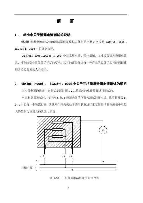
2. GB4706.1-2005 , IEC335-1:2004中关于三相器具泄漏电流测试的说明 三相用电器的泄漏电流测试是通过图1-2-1所描述的电路装置进行测试的。
对三相器具测试时,将开关a、b、c拨到关闭的位置来测试泄漏电流,然后将开关a、b、c中的每一个轮流打开,其他两个开关仍处于关闭状态进行重复测量泄漏电流值中取较图 1-2-1 三相器具泄漏电流测量电路图2.1 GB4706.1 , IEC335-1:2004中泄漏电流测试模拟人体阻抗测量电路(Measuring Device MD)简图:图1-2-23. 9625H泄漏电流测试仪产品介绍3、1 9625H泄漏电流测试仪产品介绍9625H是测试单相和三相器具泄漏电流的专用测试仪器。
可分别设置各个项目的泄漏电流报警值,测试时间。
液晶显示,具有缺相测试功能。
9625H系列测试仪泄漏电流测试精度高(优于2%),外形精巧美观,内部采用固态继电器控制,控制动作快、无交流接触器吸合时的噪声。
可选择配置串行计算机接口(RS-232/485)、遥控接口,不但能满足实验室的高精度要求,也适用于生产线快速化流水检测。
仪器的测量原理符合《GB4706.1》、《GB3883.1》、《GB4943》安全性能检测要求,符合国家计量检定规程JJG843—93 泄漏电流测试仪计量检定规程。
该系列测试仪仅适用于单相,三相三线,三相四线制家用电器、仪器仪表、电动工具的泄漏电流测试。
第一章 安全规则本章概要:z安全规定及标志z安全操作规定本规则确认泄漏电流测试前应该注意的规定和事项!1.1 安全规定及标志●使用泄漏电流测试仪之前,请认真阅读本手册,务必按照手册要求的规定进行操作。

Economic & ReliableThe Introduction to the World of Mobile pHFiveGo ™ Portable Instruments pHmV / ORP Conductivity TDS Salinity DOF i v eG o™F i v eG o™WaterNo matter whether it’s a lake or a sewage plant – compliance to cer-tain pH and conductivity values in water is vital for the sustainability of all life, be it human, plant or animal.BeveragespH value must be monitored duringvarious processing stages involved in the production of beverages to ensure that the final product has the desired flavor.FoodstuffsYogurt, cheese, fish, meat, sauces … the number of samples is virtually endless, but they all have one thing in common: The pH value must be kept at the optimum level so that quality and freshness of the products is guaranteed.AgricultureThe pH value of arable land must be monitored regularly to protect people and the environment from potential hazards and to create ideal conditions for growing agricultural products.IndustryThe pH and conductivity of cooling and cleaning water as well as the manufactured products themselves must be tested during the manufacturing process – to guarantee a high level of quality in the finished prod-ucts, to keep manufacturing costs down and to protect manufacturing equipment from corrosion and other damage.5 x 5 Reasons for FiveGo™Mobile pH, Conductivity & DO Solutions5 x self-explanatory buttons for the sim-plest operation■S imple start and finish of measurements and calibrations ■ F ast changeover between pH and mVparameters, or conductivity, TDS and salinity and also DO in %, mg/L and ppm ■ Intuitive adjustment of settings ■ S aving and accessing of measurements and calibration data at the push of a button ■ S eparate on/off switch5 x useful informa-tion on a large, well organized display■S imultaneous display of measurement, temperature and endpoint recording ■ E lectrode icon: provides information on the condition of the electrode ■C alibration/measurement icon: indi c ates that the instrument is cali-brating/measuring ■ S etup icon: settings can be modified ■ B attery icon: provides information about the condition of the battery5 x superbfunctionalities■D ata storage for 30 measurements ■ A utomatic or manual termination of a measurement or calibration ■ A utomatic or manual temperature compensation ■ A utomatic calibration with predefined pH buffer groups or predefined con-ductivity standards ■ A utomatic buffer recognition during pH calibrationOrdering Codes & Scope of SupplyTechnical Specifications5 x useful accessories■E lectrode clip can be attached to the left or right-hand side of the instrument ■ W rist strap for additional security during transport ■ “Quick Guide” – laminated, in case of spills ■ A variety of electrodes for various appli-cations, calibration solutions and clean-ing solutions ■ H andy carry bag with space for instru-ment, electrode, buffer bags, 4 sample bottles, operating manual, “Quick Guide” and spare batteries5 x outstanding price/performance ratio■M ETTLER TOLEDO quality for reliable measurements ■ C ompact design – also ideal for users with smaller hands; easy replacement of batteries ■ I P54 protection against dust and water ■ O ver 60 years of sensor know-how are also included in entry-level instruments ■ E lectrode clip, wrist strap and “Quick Guide” are included as standard with every instrument; electrode and calibra-tion sachets are included in the field kit version together with a carrying case including 4 sample bottlesElectrodes & Applications* No cable is included, a selection of cables is available for connection to various instruments, e.g. Red S7-BNC, 1.0 m(Order no. 59902392) for METTLER TOLEDO, Hanna etc. More cable information is available at /electrode-guide .Our InLab ® sensors can, of course, also be connected to our “Five” series instruments. More detailed information about our InLab portfolio is available at /electrodes.Accessories/pHMETTLER TOLEDO – the Right Solution Right from the Start……also for the laboratory: FiveEasy Plus ™ and FiveEasy ™, the compact benchtop instrument for an easy introduction to the world of pH and conductivity.METTLER TOLEDO gone Global…the contact addresses of METTLER TOLEDO representatives globally can be found under the Internet address /contacts otherwise:Mettler-Toledo AGPO Box VI-400, CH-8606 Greifensee Tel. +41-44-944 22 11Fax +41-44-944 31 70Mettler-Toledo AG, AnalyticalCH-8603 Schwerzenbach, SwitzerlandPhone +41 22 567 53 22, Fax +41 22 567 53 23 Internet: Subject to technical changes© 08/2012 Mettler-Toledo AG, ME-51724517CCalibration & Cleaning SolutionsQuality certificate.Development, production and testing according to ISO 9001.Environmentalman a gement system according to ISO 14001.European conformity. The CE conformity mark provides you with the assur-ance that our products com-ply with the EU directives.。
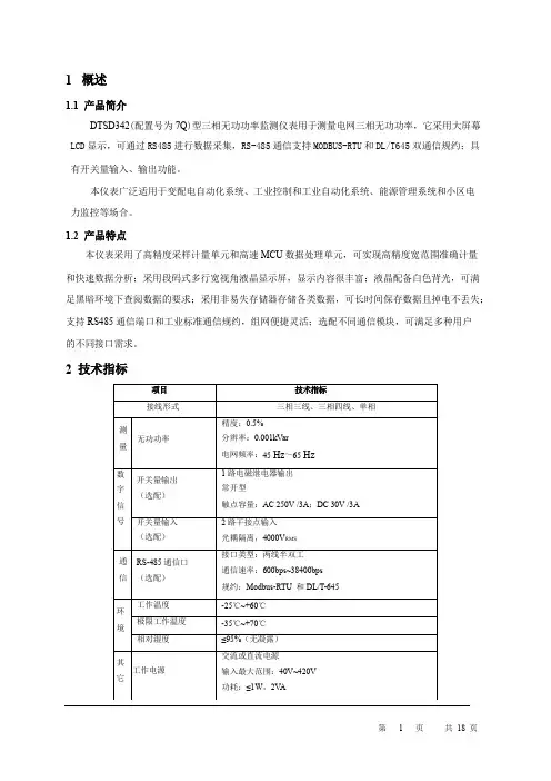
1概述1.1产品简介DTSD342(配置号为7Q)型三相无功功率监测仪表用于测量电网三相无功功率,它采用大屏幕LCD显示,可通过RS485进行数据采集,RS-485通信支持MODBUS-RTU和DL/T645双通信规约;具有开关量输入、输出功能。
本仪表广泛适用于变配电自动化系统、工业控制和工业自动化系统、能源管理系统和小区电力监控等场合。
1.2产品特点本仪表采用了高精度采样计量单元和高速MCU数据处理单元,可实现高精度宽范围准确计量和快速数据分析;采用段码式多行宽视角液晶显示屏,显示内容很丰富;液晶配备白色背光,可满足黑暗环境下查阅数据的要求;采用非易失存储器存储各类数据,可长时间保存数据且掉电不丢失;支持RS485通信端口和工业标准通信规约,组网便捷灵活;选配不同通信模块,可满足多种用户的不同接口需求。
2技术指标3功能介绍3.1参数测量功能本仪表可测量总和各分相无功功率。
3.2越限报警功能(1)仪表具备越限事件报警功能。
用户可从电压、电流、功率、功率因数和频率等参数中最多同时选择6个数据作为检测对象,对其设定高低限值和判断条件,当测量值越过设定的限值时报警。
仪表带有1路继电器输出,当报警参数配置为某继电器输出且该继电器为自动方式(非手动方式)时,越限报警信号就可通过该路继电器输出(继电器合闸)。
(2)仪表内部最多可同时设置6组越限报警参数。
各组越限报警参数的配置流程为:选择检测数据类别→设置检测数据阀值→设置判断条件→选择报警信号输出继电器。
①各类检测数据代码如下:(DL/T645代码为十进制数;Modbus-RTU代码为十六进制数)当检测数据代码为FF时表示该组越限报警功能关闭。
②检测数据阀值:检测数据是否越限的判断阀值。
不同的数据类型有不同的单位,如:电压—V;电流—A,有功—KW,无功—KV AR,视在—KV A,频率—Hz。
③判断条件:设置为0表示大于限额值报警;1表示小于限额值报警。
转辙机综合测试仪使用说明书一、开机/关机1.开机按下键并保持2-3s后,仪器开机并开始初始化自检,自检期间蜂鸣器鸣响。
初始化完毕后进入主菜单,蜂鸣器停止鸣响,进入主菜单开机完毕。
主菜单显示当前存储器通道号、当前道岔号、当前日期、时钟及电池电量。
2.关机在任意状态下,按下键后仪器即时关机,关机后关闭所有电源。
并将部分设定内容存储。
二、设定内容及操作方法1.显示液晶对比度当显示液晶受温度、光照等因数造成显示不清时,你可以通过设置液晶的显示对比度进行修正。
在主菜单下按键及键可调整液晶的显示对比度。
设定内容可自动保存。
2.显示液晶辅助背光开关当使用环境的光线不足、能见度较低,你可以开关液晶的辅助背光。
在主菜单下按键及键可开关液晶的辅助背光。
设定不可保存。
3.修改当前通道在自动、手动、显示等菜单中按键及键可改变当前的默认存储通道。
4.设置菜单在主菜单下按键后进入设置菜单,你可以在此菜单中修改道岔号、当前时钟、打印数据间隔。
1)改变当前的道岔号在设置菜单中选择1进入。
显示当前的道岔号,随光标位置输入新的道岔号后按确定完成修改。
2)调整日期、时钟在设置菜单中选择2开始进行调整。
随光标位置输入新的日期、时间后按确定完成修改。
3)修改打印数据间隔在设置菜单中选择3进行修改。
首先显示的是当前的打印数键或键来进行修改,设定范围为0.15s – 0.9s,设定间隔为 0.15s。
三、电池充电当电池电量降至30 %时,仪器的蜂鸣器鸣响,电池欠电报警,请立即停止使用,并请及时充电。
当可能较长时间不用时,请带电保存。
并请每3个月充电一次。
电池的充电时间为12-16 小时。
四、连接、联线请将综合测试线的电压测试线并接在转辙机电机电源线的任意两相上。
请将综合测试线的电流测试线串接在转辙机电源线的回路中。
请将综合测试线的时间测试线接在转辙机到位闭合的一组备用接点上。
请将拉力传感器替换转辙机与安装装置的连接销后用联线与仪器连接。
请将压力传感器替换转辙机被测压力腔侧的二动调节阀后用联线与仪器连接(只限于电液转辙机)。
三相智能测控电力仪表操作手册请首先阅读本手册©Copyright reserved安装、使用产品前请先阅读本操作手册,并保留备用121.简述1.1.仪表的功能仪表三相智能表是一款用于中低压系统(6~35kV和0.4kV)的智能化装置,它集数据采集、统计功能于一身,具有交流电参量的测量、电能计量、参数设置、本地操作等功能。
仪表提供通讯功能,支持RS485接口MODBUS通讯协议,与计算机监控系统连接。
1.2.仪表的特点1.2.1.仪表具有强大的数据采集、处理、统计与控制功能●全参数测量:支持三相三线制和三相四线制,具有三相电压、三相电流、零序电流、有功功率、无功功率、视在功率、功率因数、系统频率等全电网参数测量功能。
●计量功能:总、正向、反向有功电能;A/B/C分相绝对值有功电能;总、正向、反向无功电能;A/B/C分相绝对值无功电能;四象限无功电能。
●本地测控:所有电参量、运行状态可本地查看,参数可本地设置.1.2.2.安全性高,可靠性好仪表在设计过程中采用了多种抗干扰措施,能够在复杂的电力系统环境中稳定运行。
静电放电抗扰性符合3级;电快速瞬变脉冲群抗扰性符合3级;浪涌抗干扰性符合4级;面板防护等级符合IP50,壳体防护等级符合IP30。
1.2.3.体积小,安装方便,触摸按键仪表外形尺寸符合DIN96×96标准,壳体深度为82mm,采用自锁面板式安装机构,无需螺丝即可安装。
并采用触摸按键,有寿命长不怕污渍的特点。
1.2.4.系统接线方便灵活系统接线方式有三相四线制3CT(3P4W/3PT+3CT)、三相四线制1CT(3P4W/3PT+1CT)、三相三线制3CT(3P3W/2PT/3PT+3CT)、三相三线制2CT(3P3W/2PT/3PT+2CT)、三相三线制1CT(3P3W/2PT/3PT+1CT)。
1.2.5.显示直观、操作简便大尺寸专用液晶模块可以实时显示多项信息,配合明亮的背光,使操作者在光线差的情况下也能准确阅读数据。

GDZRS-10A 三相直流电阻测试仪产品操作手册武汉国电西高电气有限公司尊敬的用户:感谢您购买本公司GDZRS-10A三相直流电阻测试仪。
在您初次使用该产品前,请您详细地阅读本使用说明书,将可帮助您熟练地使用本仪器。
我们的宗旨是不断地改进和完善公司的产品,如果您有不清楚之处,请与公司售后服务部联络,我们会尽快给您答复。
注意事项●测量过程中不允许拆卸接线及直接关闭电源。
●对于无载调压变压器,不允许测量过程中切换分接开关。
●测量过程中如果电源突然断电,本机会自动开始放电,请不要立刻拆卸接线,至少等待30秒钟后才可拆卸接线。
●三相测量适用于YN联接的绕组,对于yn联接的绕组由于联接铜排电阻的影响,三相和单相测量结果会有所差异,建议使用单相测量。
●注意:三相方式测量的结果并不包含中性引出线的电阻值,因此建议在三相电阻值测量完以后,每相至少用单相测试方法验证一个数据,以确定中性引出线是否正常。
本手册内容如有更改,恕不通告。
没有武汉国电西高电气有限公司的书面许可,本手册任何部分都不许以任何(电子的或机械的)形式、方法或以任何目的而进行传播。
目录一、概述 (4)二、性能指标 (4)三、面板说明 (5)四、测试及操作方法 (6)五、注意事项 (13)六、故障分析与排除 (14)七、运输、贮存 (14)八、开箱及检查 (15)九、其它 (15)GDZRS-10A 三相直流电阻测试仪一、概述本直流电阻测试仪(以下简称直阻仪)是变压器直流电阻测量的最新一代产品,是为测量大容量变压器三相绕组直流电阻而优化设计的。
可对变压器的三相绕组直流电阻进行同时测试。
对有载调压变压器可以不需要放电,直接调节分接开关,测量时间是传统单相测量的三分之一,可大大缩短工作时间和劳动强度。
直阻仪采用大屏幕液晶显示器,全中文图形界面,清晰直观,操作非常简单。
并配备面板式打印机和大容量非易失性存储器,可以方便的存储和打印测量结果。
测试数据稳定,快速,重复性好,是现场测量变压器直流电阻的最佳选择。
DY5103型多功能测试仪操作规范DY5103型多功能测试仪是电力从业人员的常用检测设备,因使用频率高,为避免仪器因使用不当造成损坏,同时提高产品测试数据的有效性、真实性和准确性,亟需一套完整的仪器操作规范。
标签:绝缘电阻测试;泄漏电流测试;接地电阻;耐压测试0 引言DY5103型多功能测试仪是多一公司研发的新一代全能型电工测试仪表。
它对传统的绝缘电阻、接地电阻仪的电路工艺进行了根本改革,功能更全更强,操作更方便可靠。
产品和配件统一放入工具箱,适合野外作业使用,它可用于检测电力系统、电气设备、防雷设备等的绝缘电阻、接地电阻,并可测量交流电压、相序检测和辅助进行耐压测试的工作[1]。
1 DY5103型多功能测试仪绝缘电阻测试操作规范操作方法及要点详解。
在绝缘电阻的测试实操中,应严格遵循以下步骤:(1)将设备与电源相连接,确保仪器处于工作运行模式,将两根电源连接线准确的连接至被测试体上。
(2)要确定电压量程,根据阻值确定被测试体的量程。
(3)进行测试,如果测试过程中表头数值显示是“1”则表示现用测试值已经超出被测试体的适合量程,要在更换量程后再继续进行测试;如果被测试体有故障问题,则应在断电排除问题后再继续进行测试,并对上一批次被测试体进行重检。
(4)测试完成后,请安全的将电源连接线与被测试体分离。
(5)对于不合格产品应以返工方式进行处理。
每次完成测试后,应断电、仪器归零、妥善保存以禁止非相关人员触碰。
2 DY5103型多功能测试仪泄漏电流测试执行规则具体执行规则。
(1)确保测试仪器归零,然后接通电源。
(2)按“13”,设定漏电预置值为“12”,以1000Ω/1750Ω为测试阻值。
(3)打开开关,输出测试标准电压,复位。
(4)开始测试,对被测试体的L/N相皆进行测试。
将“16”开关预置为定时,设定所需时间,然后输出测试所要求之标准电压以开始定时检测;将“16”开关预置为定时,手动进行检测。
测试时如输出电流超出预置则在报警装置响起后断电,按动复位所用之开关使全组仪器回动至初始状态。
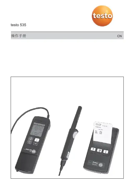
testo 535操作手册CN探头应尽量远离您的身体。
以避免因呼吸产生的CO 2影响测量结果。
连接电源适配器连接 (订货号:0554 0088) 适用于长期测量2 行显示保持/最大/最小 均值开始/结束开机/关机旋开电池仓打印仪器符合 2004/108/EEC.自动关机功能更换电池若屏幕显示“Bat“符号,仪器可用时间将不足1小时(电池总使用时间约4小时)。
电池电量不足时,仪器会自动关机。
打开电池仓,拆下旧电池,装入新的9V (IEC 6F 22)电池。
注意电池极性!没有电池情况下,用户设置会被保留3分钟。
Operation 操作开启仪器,仪器进行自检,并且传感器进行加热(约30秒),加热过程结束后,仪器可进行操作。
CO 2探头需1分钟左右适应周围环境,前后轻摇探头可缩短探头适应时间。
testo 535技术数据传感器: 2通道红外吸收原理 测量范围: 0 ~ 9,999 ppm CO 2 (0 ~ 0,999 vol.% C O 2) 精度: 0 ~ 5000 ppm:(在 23 °C 下 *) ± (75 ppm +3 % 测量值) 5000 ~ 9,999 ppm: ±(150 ppm +5 %测量值 分辨率: 1 ppm 或 0.001 vol.% 操作温度: 0 ~ +50°C 存放温度: -20 ~ +50 °C 电池寿命: >4h (9 V 块状, Al-Mn) 单位切换: ppm / vol. %显示: LCD (11 mm 数位高度) 外壳材质: ABS尺寸: 190 x 57 x 42 mm 重量:约300 g环境湿度: 0 ~ 99 %RH (非冷凝)保修testo 535测量仪................1年2* 温度系数: ± (1 ppm + 0,4 % 测量值) / °C处理电池说明:只有电量耗尽的电池可被处理。
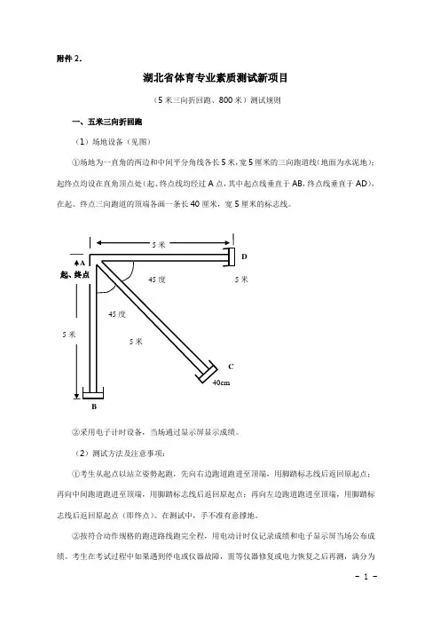
附件2.湖北省体育专业素质测试新项目(5米三向折回跑、800米)测试规则一、五米三向折回跑(1)场地设备(见图)①场地为一直角的两边和中间平分角线各长5米,宽5厘米的三向跑道线(地面为水泥地);起终点均设在直角顶点处(起、终点线均经过A点,其中起点线垂直于AB,终点线垂直于AD),在起、终点三向跑道的顶端各画一条长40厘米,宽5厘米的标志线。
②采用电子计时设备,当场通过显示屏显示成绩。
(2)测试方法及注意事项:①考生从起点以站立姿势起跑,先向右边跑道跑进至顶端,用脚踏标志线后返回原起点;再向中间跑道跑进至顶端,用脚踏标志线后返回原起点;再向左边跑道跑进至顶端,用脚踏标志线后返回原起点(即终点)。
在测试中,手不准有意撑地。
②按符合动作规格的跑进路线跑完全程,用电动计时仪记录成绩和电子显示屏当场公布成绩。
考生在考试过程中如果遇到停电或仪器故障,需等仪器修复或电力恢复之后再测,满分为- 1 -100分。
Ⅰ未按规定跑进路线跑完全程计“0”分。
Ⅱ如果有一个顶端标志线未踏,判为未跑完全程,按0分计。
Ⅲ有意用手撑地(获得利益)判“0”分。
成绩为0分者,可重测一次,最终成绩按考生重测成绩扣除该项目总分的10%计算(即扣掉10分)。
继续为0分者,可再重测一次,成绩按考生成绩扣除该项目总分的20%计算(即扣掉20分),每位考生最多只可重测两次。
(3)异常情况处理①考生在测试前因伤、病不能按规定时间参加测试,要求缓考的,应由考生本人提出缓考申请,并提供三甲以上医院证明,经省教育考试院体育专业素质测试领导小组同意,方可安排缓考,否则视为考生自动弃权。
在全省体育测试工作全部结束前仍不能参加测试的,视为自动放弃测试。
②如测试过程中摔倒,既可继续坚持测试,也可以申请重测,重测成绩按测试方法及注意事项中重测的规定计算。
二、中长跑(男子800米,女子800米)(1)场地设备①400米标准场地,正规比赛用橡胶跑道,设两条起跑线,第二起跑线左侧弯道线上每间隔5米摆放锥型标志物,在第一弯道与直道处设抢道标志杆。
ENGLISHDL599Wireless TRMS Clamp Meter w/ 3-Phase & Unbalanced Motor Tests1-800-547-5740•email:****************FUNCTIONS (3)FEATURES (3)GENERAL SPECIFICATIONS (3)IMPORTANT SAFETY WARNINGS (4)SYMBOLS (5)CATEGORY DEFINITIONS (5)OVERVIEW .....................................................................................6 - 7 OPERATING INSTRUCTIONSNon-Contact Voltage (7)Voltage: 1000V AC/DC (8)Frequency (Hz) / Duty Cycle (9)Low Z (Low Impedance) (10)Low Pass Filter (10)AC/DC Amps: <600A – Jaw (11)AC/DC Microamps: <2000μA (12)Zero DC Amps (12)LRA Inrush (13)Phase Rotation (13)Voltage Unbalance (14)Current Unbalance (14)Resistance: < 60MΩ (15)Temperature F˚/C˚ (15)Diode (16)Capacitance (17) (17)ContinuityApp Overview (18)Test Lead Notes (19)FCC/IC (19)WARRANTY (20)BATTERY REPLACEMENT (20)DISPOSAL (20)CLEANING (20)STORAGE (20)• True RMS• 1000V AC/DC• 600A AC/DC• Differential temperature • AC/DC microamps: 2000µA • Capacitance: 9999µF • Frequency: 99.99kHz • Duty cycle• Diode test• Audible continuity • NCV• LRA Inrush• DC Zero• Temperature range: -328˚ to 2462˚F • Resistance: 60MΩ• 3-Phase Rotation Test• Motor Unbalanced Test• Low Z (Low Impedance)• Low Pass Filter• Wireless capability • Free App• Dual display• Auto/Manual ranging • Worklight• Back light• Low battery indicator • Data Hold • Auto power off• Test lead storage• Auto calibration• Built-in Magnet w/ hanging strap • Visible high-voltage alert• Input jack locks• Min/Max/Avg• Auto selection (voltage & amps)•Operating Temperature: 32˚ to 122˚F (0˚ to 50˚C)•Storage Temperature: -4˚ to 140˚F (-20˚ to 60˚C)• Operating Humidity: <80%•Pollution Degree: 2•Display: 3 5/6 digits 6,000 count•Back light: Yes•Refresh Rate: 3/sec•Over-range: “OL” is displayed•Apo: Auto power off after 30 minutes of use.•Dimensions: 9.45” x 2.58” x 1.67”•Item Weight: 0.926 lb.•CAT Rating: CATIV 600V•Certifications: cETLus UL 61010-1: 2012, IP42, 6 ft. Drop Protection •Battery Type: (AAA) 4•Test Leads: Test leads w/ alligator clips & back probesUse ATL58 test leads w/ ABP3 back probes andAAC3 alligator clips.ATL55, ATL57 and ATLTX will not work with DL599Read entire Safety Notes section regarding potential hazards and proper instructions before using this meter. In this manual the word “WARNING” is used to indicate conditions or actions that may pose physical hazards to the user. The word “CAUTION” is used to indicate conditions or actions that may damage this instrument.WARNINGTo ensure safe operation and service of the tester, follow these instructions. Failure to observe these warnings can result in severe injury or death.WARNING• Before each use, verify meter operation by measuring a known voltage or current.• Never use the meter on a circuit with voltages that exceed the category based rating of this meter.• Do not use this meter during electrical storms or in wet weather.• Do not use the meter or test leads if they appear damaged.• Ensure meter leads are fully seated and keep fingers away from the metal probe contact when making measurements. Always grip the leads behind the finger guards molded into the probe. For information on test lead shields instructions on page 19.• Do not open the meter to replace batteries while the probes are connected. • Use caution when working with voltages above 60 DC or 25 AC RMS. Such voltages pose shock hazards.• To avoid false readings that can lead to electrical shock, replace batteries if a low battery indicator appears.• Unless measuring voltage or current, shut off and lockout power before measuring resistance or capacitance.• Always adhere to national and local safety codes. Use proper personal protective equipment (PPE) to prevent shock and arc blast injury where hazardous live conductors are exposed.• Always turn off power to a circuit or assembly under test before cutting, unsoldering or breaking the current path. Even small amounts of current can be dangerous.• Always disconnect the live test lead before disconnecting the common test lead from the circuit.• In the event of electrical shock, ALWAYS bring the victim to the emergency room for evaluation, regardless of victim’s apparent recovery. Electrical shock can cause unstable heart rhythms that may need medical attention.• If any of the following occur during testing, turn off the power source to the circuit being tested: arcing, flame, smoke, extreme heat, smell of burning materials or discoloration or melting of components.WARNINGHigher voltages and currents require greater awareness of physical safety hazards. Before connecting the test leads; turn off power to the circuit under test, set meter to the desired function and range; connect the test leads tothe meter first, then connect to the circuit under test. Reapply power. If an erroneous reading is observed, disconnect power immediately and recheck all settings and connections.WARNINGThis meter is designed to provide HVAC/R technicians with the capabilities they need to diagnose and repair HVAC/R system. Observe all recommended safety procedures that include proper lockout utilization and use of personal protective equipment that includes safety glasses, gloves and flame resistant clothing.AC (Alternating current)DC (Direct current)Negative AC/DC Voltage or CurrentAuto-ranging Overload: Range ExceededkHz Low pass Filter BT Wireless Connection Auto power off Active Non-Contact VoltageLow Battery Hold/Capture ValueMinimum measured value displayed Maximum measured value displayedDuty Cycle Hertz/FrequencyVoltage InrushAmperage Ohms/ResistanceDiode CapacitanceNanofaradµF MicrofaradMicroamps ContinuityDegrees Fahrenheit Degrees CelsiusMega (x106 or 1,000,000)Milli (x10-3 or 0.001)Kilo (x103 or 1,000)Micro (x10-6 or 0.000001)Warning or Caution GroundDangerous Levels Double Insulation(Protection to Class II) Safe for disconnect fromlive conductors No reading detected AVG Average EF Electric FieldT1Temperature input 1T2Temperature input 2 M Mega Ohms k Kilo OhmsMeasurement Category Short-Circuit(typical) kA aLocation in thebuilding installationII< 10Circuits connected to mains socketoutlets and similar points in the MAINSinstallationIII< 50Mains distributions parts of the building IV> 50Source of the mains installation in thebuildingA. Clamp: Measure inductive AC/DC current. Opens to 1.25” (32.0mm).B. Conductor Alignment Marks: Use to aid the visual alignment of a c onductor when measuring inductive amperage. Greatest accuracy i s achieved when the conductor inside the clamp is centered at the intersection of these marks.C. Worklight: Lights clamp area in dark work environments.D. Category Max Indicator: Maximum CAT Rating for clamp jaw.E. NCV Alert Light: Indicates voltage when in NCV (Non Contact Voltage) mode and High Voltage alert.F. Clamp Lever: Opens and closes current clamp jaw.NOTE: The clamp uses a high-tension spring to close the jaw. Do not allow fingers or objects to become pinched in the base as the jaws close.G. Rotary Selector Dial: Set Rotary Selector Dial desired function H. SELECT/Wireless (BT) Button :• Press to select AC or DC on Low Z setting, AC or DC on voltage setting, AC or DC on Amps setting.• Press to activate Ohms, Continuity, Diode, Capacitance on Ohms/Continuity/Diode/Capacitance setting; AC or DC on Low amps setting; T1, T2, T1 - T2 on temperature setting. • Press and Hold to activate Wireless mode.I. Range/Mode/kHz Button:• Press to set manual range desired• Press and hold Range/Mode/kHz Button to activate Low filter mode J. Min/Max/Test Button:• Press to capture Max reading• Press again to capture Min reading • Press again to capture Avg reading • Press and hold return to Live readings• Press and hold Min/Max/Test Button and Range/Mode/kHz Button to activate Motor measurement test modeI LK. Category Max Indicator: Maximum CAT Rating for input jacks.L. Test Lead Input Jacks: Multifunction and Positive input jacks.• Multifunction input port used for measuring: AC or DC volts, resistance, continuity, diode, capacitance, AC or DC µA.M. Wire Separation Tab/ NCV sensor: Use to isolate an individual wire from a bundle for testing. NCV sensor detects live voltage.N. T est Lead HolderO. Hand Guide: Used as a point of reference for the operator’s safety.P. Hold/Worklight/ Back light Button:• Press to hold the reading on the display. Press again to return to livereading.• Press and hold to turn on Worklight and Back light. Press and holdagain to turn off.• Worklight and Backlight turn off after 60 seconds.Q. Display:• High contrast dual display with backlit.• Amps (AC/DC) reading will always display on upper display.R. LRA Inrush/Zero/˚C/˚F/Hz/Duty Button:• Press to Zero the DC Amps reading.• Press to enter LRA Inrush mode (See page 13 for details)(must be in AC Volts mode first).• Press again to return to live readings.• Press and hold to select ˚F or ˚C in temperature settingS. K-Type Temperature Probe Inputs: T1 (Left) and T2 (Right))T. Input Jack Lock: Switch to use Temperature or Test lead inputsU. Built-in versatile magnet to use as a mount or as a strapV. Battery Cover: Easy access for replacing batteries without breaking calibration seal.W. Battery Compartment Latches:X. Serial NumberNCV Sensor in the tip.• Rotate Rotary Selector Dial to NCV position move the tip of the clamp meter near voltage source.• Non-Contact Voltage Detection is used to detect power with sensor located in the tip of the clamp head, indicates positive response with both an Audible and Visual alert.• Do not use Non-contact voltage detector to determine if there is current on the wire. Detection operation could be affected by socket design, insulation thickness, type or other factors.• Voltage indicator light may also light when voltage (>AC/DC 30V) is present on the meter’s input jack or from an external interference such as motors, flashlights, etc.WARNING• Use CATIII rated test leads or higher.• Do not attempt to measure more than 1000V AC/1000V DC.• Keep hands below line when measuring high current levels.• Select AC or DC Voltage.WARNING• High Voltage indicator will display and audible alert will sound over 600V AC/DC• AC/DC and High Voltage indicator will display (without audible alert) over30V AC/DCAC VoltsUse CAT III rated leads or higher.Press the SELECT button to select AC voltage, press and hold the button for Frequency and Duty Cycle modes.WARNINGDo not attempt to measure more than 1000V AC/1000V DC.Frequency Measurement - Test lead input Sensitivity: 1.8VrmsFrequency Measurement - Jaw inputdd Low Pass Filter• Opposing currents cancel each other (use line-splitter when necessary). • Keep hands below guard when measuring high current levels.• Do not attempt to measure more than 600A AC / 600A DC.AC Amps Measurement - Jaw inputMinimum Current for Clamp Measurement: 0.3ADC Amps Measurement - Jaw inputWARNING• Do not attempt to measure more than 2000µA.Select DC current.• Press to zero any offset in Amps DC.• Used to monitor change from present displayed value.• Required during DC Amps measurement to establish a zero level. WARNINGDo not use DC Zero mode at amps greater than 600A DC.Zero DC Amps• Press SELECT x1 = • Press SELECT x2 =• Press ZERO = DC Amps Zero• Press SELECT x1 =The UEi LRA Inrush is programmed to properly capture the starting current for compressor motors.• Select AC Amps.• Select the range capable of capturing the maximum value.• Press the ZERO button – INRUSH will now be shown on the screen.• Activate the compressor and read value on the display.• Press the Zero button to return to live readings.Phase Rotation1. Set Dial to V range2. Press and hold RANGE and MIN/MAX button to enter Phase rotation mode. Upper display shows “3Pha”3. Press Min/Max button to enter standby modeUpper display blinks “L1L2”NOTE: Each of steps 4 -5 needs to be conducted within 5 seconds. If not, the display will indicate “oVEr” and the meter will finish the testing.4. Connect test leads to any two lines (L1 – L2) of 3-Phase voltage lines.A beep indicates stable voltage is captured, and the Upper display shows “L1L3”5. Remove Red test lead from the voltage lineA beep and “L3” blinking on display will indicate test is ready.6. Connect Red test lead to the third voltage line (L1 – L3)A beep indicates test is completeUpper display indicates phase status (Forward or Reverse).1. Set the Dial to V range2. Press and hold RANGE and MIN/MAX button to enter Phase rotation mode. Press RANGE button to enter Voltage Unbalance test modeUpper display indicates “V1V2”Press Min/Max button to enter Testing standby mode.“V1V2” will blink on displayNOTE: Steps 3 - 4 needs completed within 30 seconds. If not, the display will indicate “oVEr” and the meter will finish the testing.3. Connect test leads to any two lines (V1 – V2) of the 3-Phase voltage linesA beep indicates stable voltage is captured, and the Upper display shows “V1V3”4. Remove Red Test lead from the voltage lineA beep and “V1V3” blinking on display will indicate test is ready. Connect the Red test lead to the third voltage line (V1 – V3)5. A beep indicates test is completeUpper display will indicate test result (PASS or FAIL)Lower display will indicate the percentage:PASS % unbalance <2%FAIL % unbalance > 2%% V unbalance = (Max deviation from Avg Voltages/Avg Voltage) x 1001. Set the Dial to A range2. Press and hold RANGE and MIN/MAX to enter Current Unbalance test mode Lower Display will indicate “A”3. Press Min/Max button to enter testing standby mode“-A1-” will blink on displayNOTE: Each of steps 4 – 6 needs to be conducted within 30 seconds. If not, the display will indicate “oVEr” and the meter will finish the testing.4. Clamp the jaw around current line (A1)A beep indicates stable current is captured, and the Lower display shows “-A2-“Remove clamp jaw from current lineA beep and “-A2-“ blinking on display will indicate test is ready.5. Clamp the jaw around current line (A2)A beep indicates stable current is captured, and the Lower display shows “-A3-“Remove clamp jaw from the current lineA beep and “-A3-“ blinking on display will indicate test is ready.6. Clamp the jaw around current line (A3)A beep indicates stable current is capturedUpper display indicates test results (PASS or FAIL)Lower display will indicate the percentage:PASS % unbalance <10%FAIL % unbalance > 10%% I unbalance = (Max deviation from Avg Currents/Avg Currents) x 100WARNING• Disconnect test lead probes from voltage source and meter. • Move Input Jack Locks to “TEMP” setting.• Use K-Type thermocouple temperature probes only.• Stated accuracy does not account for thermocouple accuracy.Temperature F˚/C˚GOOD DIODE• Forward voltage drop if forward biased.• “O.L.” if reverse biased.Diode Test • Press SELECT x2 =WARNING To avoid damaging the meter or equipment under test, safely discharge Capacitors before measuring capacitance. Large value capacitors should be discharged through an appropriate resistance load. Use the DCVoltage function to confirm the capacitor discharge.• Buzzer sounds at less than < 40Ω.WARNING• Do not measure resistance on a live circuit.Continuity• In the App stores Google Play and the App Store, search “DL599”.• App is compatible with iOS® 12.0 and up and Android™ 6.0 and up.• If searching for the iPad version, you may have to filter for “iPhone” only.• Turn on DL599 and launch the DL599 App on device.• On DL599, Press and hold SELECT / BT. Beep confirms wireless mode activated. BT shows in display.• On Device, Press CONNECT • Devices should pair.A F G HB DECA. Menu screen• Connection Status • Settings screen • Info (Manual) • UEi AppB. BT connection indicationC. Graphing screen: View live graphingD. Display: Reading mirrors DL599 displayE. Function Buttons: Operation mirrors DL599 function buttons• 3-Phase Rotation, Voltage Unbalance and Current Unbalance test processes must be started from the meter, but can be completed from the App screen.F. Log screen• Tap to select a log file to view• Swipe left to edit (rename or add memo notes) or delete SUMMARY: Default• In the summary screen, the red/ button is for displaying a graph of the JAW measurement value, and the black / button is for displaying a graph of the Test lead Input jack measurement value.• Each graph can be shown or hidden by pressing the button. SAMPLE: View individual samples from readings To exit to main menu G. Record / Stop ButtonH. Sample count: Only visible while logging•Ensure the test lead shield is pressed firmly in place. Failure to use the CAT IV shield increases arc-flash risk.CAT II Measurement Locations• CAT IV shields may be removed for CAT II locations. This will allow testingon recessed conductors such as standard wall outlets. Take care not to loseWARNING: Test Lead category protections apply only to test leads and should not be confused with the meter’s specific CAT rating. Observe themaximum category protection indicated on the meter the test leads are plugged into.CAUTION : If the test leads need to be replaced, you must use a new one which should meet EN 61010-031 standard, rated CATIII 1000V or better.NOTE: DL599 works with UEi ATL58 test leads, ABP3 back probes and AAC3 alligator clips.ABP3 Back Probes screw-on to test leads, after removing CATIV shields from test leads. Back Probes come with covers on probe tips.FCC INFORMATIONNOTE: This equipment has been tested and found to comply with the limits for a Class B digital device, pursuant to part 15 of the FCC rules. These limits are designed to provide reasonable protection against harmful interference in a residential installation.This equipment generates, uses and can radiate radio frequency energy and, if not installed and used in accordance with instructions, may cause harmful interference to radio communications. However, there is no guarantee that interference will not occur in any particular installation. If this equipment does cause harmful interference to radio or television reception, which can be determined by turning the equipment on and off, the user is encouraged to try and correct the interference by one or more of the following measures: • Reorient or relocate the receiving antenna.• Increase the separation between the equipment and receiver.• Connect the equipment into an outlet on a circuit different from that to which the receiver is connected.• Consult the dealer or an experienced radio/TV technician for help.CAUTION Changes or modifications not expressly approved by the manufacturer responsible for compliance could void the user’s authority to operate the equipment.(1) this device may not cause interference, and(2) this device must accept any interference, including interference that mayThe DL599 is warranted to be free from defects in materials and workmanship for a period of 2 years from the date of purchase. If within the warranty period your instrument should become inoperative from such defects, the unit will be repaired or replaced at UEi’s option. This warranty covers normal use and does not cover damage which occurs in shipment or failure which results from alteration, tampering, accident, misuse, abuse, neglect or improper maintenance. Batteries and consequential damage resulting from failed batteries are not covered by warranty.Any implied warranties, including but not limited to implied warranties of merchantability and fitness for a particular purpose, are limited to the express warranty. UEi shall not be liable for loss of use of the instrument or other incidental or consequential damages, expenses, or economic loss, or for any claim or claims for such damage, expenses or economic loss.Warranty only covers hardware and does not extend to software applications.A purchase receipt or other proof of original purchase date will be required before warranty repairs will be rendered. Instruments out of warranty will be repaired (when repairable) for a service charge.For more information on warranty and service, contact:•Email:****************1-800-547-5740This warranty gives you specific legal rights. You may also have other rights, which vary from state to state.DisposalCAUTION:This symbol indicates that equipment and its accessories shall be subject to separate collection and correct disposal.CleaningPeriodically clean your meter’s case using a damp cloth. DO NOT use abrasive, flammable liquids, cleaning solvents, or strong detergents as they may damage the finish, impair safety, or affect the reliability of the structural components.StorageRemove the batteries when instrument is not in use for a prolonged period of time. Do not expose to high temperatures or humidity. After a period of storage in extreme conditions exceeding the limits mentioned in the General Specifications section, allow the instrument to return to normal operating conditions before using it.。
五米三项测试方法《五米三项测试方法,包教包会!》嘿,朋友!今天我要跟你唠唠五米三项这个测试,这可是个有点小挑战,但掌握了方法就能轻松应对的事儿。
首先啊,咱们得搞清楚啥是五米三项。
简单说,就是在规定的距离内,快速地完成折返跑、转身等动作,考验你的速度、灵敏还有反应能力。
那下面咱就正式开始讲讲咋搞这个测试。
第一步,做好热身。
这就好比你要去打仗,不得先把自己的“武器”和“身体”准备好嘛!热身可不能随便比划两下,得认认真真地把关节活动开,脖子扭扭,屁股扭扭,手腕脚腕都转转。
想象一下,要是没热身好,一跑起来“咔嚓”一声,那可就惨咯!我有次就没好好热身,结果跑着跑着,感觉腿都不是自己的了,那滋味,别提多难受啦!第二步,掌握起跑姿势。
这起跑姿势就像火箭发射的点火瞬间,姿势不对,速度就起不来。
双脚前后开立,前脚靠近起跑线,膝盖微微弯曲,重心前倾,就像一只准备扑出去的豹子。
眼睛死死盯着前方,心里想着“我要飞啦!”第三步,折返跑技巧。
跑到折返点的时候,可别像个醉汉一样晃晃悠悠地转身,要迅速降低重心,用内侧脚为轴,快速转身。
这时候,身体要灵活得像个泥鳅,“哧溜”一下就转过去了。
我跟你说,有次我转身的时候慢了,感觉自己就像个被卡住的陀螺,别提多尴尬了。
第四步,保持节奏。
别一开始像打了鸡血一样冲得飞快,后面就没力气了。
要像跑马拉松一样,合理分配体力,找到自己的节奏。
想象自己是个节拍器,“滴答滴答”,稳稳地前进。
第五步,注意呼吸。
别光顾着跑,忘了喘气儿。
大口大口地呼吸,不然缺氧了可就完蛋啦!就像拉风箱一样,有规律地吸气呼气,这样才能保证你有足够的氧气供应。
在整个测试过程中,要时刻提醒自己,集中注意力,别被旁边的啥东西给吸引走了。
心里就想着“我要冲!我要快!”总之,五米三项测试,只要你按照我说的这些方法来,多练几次,肯定能取得好成绩。
加油吧,朋友!相信你行的!。
xm-05b-3计米器调试说明书
摘要:
1.概述
2.安装与连接
3.调试步骤
4.注意事项
5.故障排除
6.结束语
正文:
1.概述
xm-05b-3 计米器是一款高精度的计数设备,适用于各种需要计数的场合。
本说明书旨在帮助用户正确安装、调试和使用本设备。
2.安装与连接
首先,选择一个合适的安装位置,确保设备不会受到振动、潮湿或者高温的影响。
然后,根据设备的接线图,正确连接电源线和信号线。
3.调试步骤
(1)打开设备电源,检查设备是否正常工作。
(2)使用调试工具,如示波器或者万用表,检查设备的输出信号是否稳定。
(3)通过调整设备的参数,如触发频率、计数范围等,确保设备满足使用要求。
(4)进行实际测试,检查设备的计数是否准确。
4.注意事项
(1)在安装和调试过程中,应避免对设备进行剧烈的振动和冲击。
(2)设备在工作过程中,应保持良好的通风环境。
(3)如果设备出现异常情况,应立即停止使用,并联系专业人员进行维修。
5.故障排除
如果设备出现故障,应首先检查设备的电源线和信号线是否连接正常,然后检查设备的参数设置是否正确。
如果问题仍然存在,应联系设备的生产厂家或者专业维修人员进行处理。
6.结束语
本说明书提供了关于xm-05b-3 计米器的安装、调试和使用的基本信息。
BR-1型五米三向测试仪使用说明书
一、五米三向测试仪装箱单
名称数量
主机1个
3米连接线材11根
5米连接线材1根
电源线1根
音频线1根
红外传感器13个(1个备用)
三角架1个
底座3个
音箱1个
收纳箱1个
移动电源1个(选配)
二、仪器的安装
1,五米三向场地平面图
安装步骤:
1、将三块镀铬底座置于图中3A 3B 6A 的位置,三角架置于6B 的位置。
2、按图摆放好各传感器,数字相同字母不同的传感器(如2A ,2B )位置可互换。
3、将主机置于3号和2号传感器之间(如图)。
4、使用线材依次连接:3B-主机-2B-6A-2A-4B-4A-5B-5A-3A-1A-6B-1B
5、按下页插图连接好主机与音箱,主机与显示屏间电源线和数据线。
6、接通电源(移动电源请按住开关键3秒方可开机)。
7、开机完成后,按2键进入“调试系统”,进行调试。
8、按下“返回”键开始测试。
传感器的摆放
注意:
1, 横放时,同一对传感器底部和底部应置于同一端。
1.2米
2米
主机位置
光线
透射
2,同一对传感器的两条光线透射槽正对.
3, 标有竖放的传感器竖放在底板上,其余的
均为横放.
4, 5A 和3A 之间用5米的线连接,其它传感
器之间均用3米的线连接.
5. 尽量避免阳光直射传感器,阳光太强会影
响传感器工作。
主机连线
显示屏通讯线
三、主机的操作
1、主机的两种工作状态:
1、测试状态:按“返回”键或按下相应菜单前的数字,进入测试状态,如下图按1进入五米三向测试,按4进入三角障碍测试
2、设置状态(下图为设置状态):正在进行测试时,按“菜单”键会回到设置状态,如下图。
2、设置状态下的菜单
3、如何调试系统
第1步:设置状态下按下数字‘2’进入系统调试,出现如下屏幕
其中1A,1B等代表相应标识的传感器还没有和主机连接好。
其中OK 代表该传感器已连接好了,上图代表4A 和4B已连接好了。
当全部显示为OK时,可以进入下一步。
第2步:在键盘上按下‘确定’键进入下一步,显示如下
这时主机会检测红外传感器是否已经对好了。
如果全部对好,会显示OK,上图代表1号传感器和3号传感器没有对好,请适当移动相应的传感器。
第3步:当全部显示为OK时,按‘确定’键进入下一步,显示如下
这时按下‘1’就可以调试1号传感器的位置是否准确。
按下2就表示调试2号传感器的位置是否准确。
按‘2’时会显示如下。
这时您走到2号传感器的位置,用脚去试探光线位置,当光线被挡住时,主机会发出滴滴的声音。
没有挡住时停止发声。
如果位置不对,再适当移动传感器位置。
这个传感器调试完成后,按‘确定’开始选择下一个要调试的传感器。
3、如何使用‘三角跑测试’
三角跑要用到的有‘3A 3B 6A 6B 主机’
其中3A 3B 垂直于起跑跑道。
6A 6B垂直于冲刺跑道。
如何摆放请参考
jy52.上的三角跑测试仪器安放。
四、常见问题
1、为什么还没到就听到“嘟..”的声音了?
原因办法
传感器没有对好重新调整,参考“系统调试――无屏”
传感器间距太远请间距调整到1.2米左右
阳光太强烈如果是3号传感器,请试着横放。
2、为什么没有声音了?
3、主机显示屏看不清了?
4、为什么按键总不灵?。