dell poweredge t310
- 格式:pdf
- 大小:2.67 MB
- 文档页数:2
完整的存储解决方案采用Dell™存储解决方案轻松改变您的存储基础架构,以满足不断变化的业务需求。
借助EqualLogic® PS系列的虚拟化架构,可帮助确保最大限度的灵活性,同时保持您的整合战略。
EqualLogic使您可以部署和重新部署物理存储阵列并在存储池或存储层之间切换工作负载(数据卷),而无需停止应用程序。
在加入PS6000后,贵公司的管理员便可从PS5000或先前的阵列上,将数据库应用程序以在线方式迁移到高性能SSD系统,或针对需要PS6000系列额外带宽的应用程序进行移转。
为了适应当前迅速变化的业务需求,戴尔提供了一系列可根据您的投资来构建的解决方案,以避免代价不菲的“淘汰并取代”式方案。
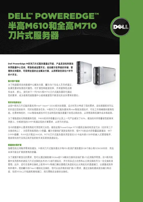
明智的投资全球性的经济挑战给企业收入带来的压力正日益显著。
首席信息官正在评估IT预算,设法提高生产效率并降低成本。
M系列是智能化的解决方案,可帮助保护您的基础架构投资,简化您的IT环境,并在功效和生产效率方面切实推进可持续的节约。
M系列投资可以节省以前用于维护的时间和资金,使您可以将其用于真正的创新。
戴尔M系列刀片式服务器与惠普和IBM的刀片式服务器解决方案相比,具有最低的总拥有成本(TCO)。
1• 面向未来的无源中板能够支持多代刀片式服务器和即将推出的全系列I/O技术• FlexIO技术可消除“淘汰并取代”式的刀片式交换机升级;交换机已经内置了模块化技术• FlexAddress提供分配了插槽的永久WWN/MAC/iSCSI以便于维护,并且无需额外的管理工具或专有硬件,从而简化了服务器和网络团队之间的工作和交接事务• 智能节能技术包括低气流风扇和高效电源,为您带来杰出的能效简化的系统管理下一代Dell OpenManage™管理工具套件使您可以掌控全局。
这些工具提供了增强的操作和基于标准的命令,可与现有系统集成以便有效控制。
戴尔管理控制台(DMC)将基础架构管理缩减到一个控制台中,这有助于简化操作和建立稳定性。
Dell Precision 3530Solid State Drive Installation GuideNotes, cautions, and warningsNOTE: A NOTE indicates important information that helps you make better use of your product.CAUTION: A CAUTION indicates either potential damage to hardware or loss of data and tells you how to avoid the problem.WARNING: A WARNING indicates a potential for property damage, personal injury, or death.© 2018 Dell Inc. or its subsidiaries. All rights reserved. Dell, EMC, and other trademarks are trademarks of Dell Inc. or its subsidiaries. Other trademarks may be trademarks of their respective owners.2018 - 05Rev. A001 Before you begin (4)Safety instructions (4)Before working inside your computer (4)Safety precautions (5)Electrostatic discharge—ESD protection (5)ESD field service kit (6)Transporting sensitive components (7)After working inside your computer (7)2 Solid State Drive (8)Installing the Solid State Drive (8)3 Getting help (15)Contacting Dell (15)Contents3Before you begin Safety instructionsUse the following safety guidelines to protect your computer from potential damage and to ensure your personal safety. Unless otherwise noted, each procedure included in this document assumes that the following conditions exist:•You have read the safety information that shipped with your computer.•A component can be replaced or, if purchased separately, installed by performing the removal procedure in reverse order. WARNING: Disconnect all power sources before opening the computer cover or panels. After you finish working inside thecomputer, replace all covers, panels, and screws before connecting to the power source.WARNING: Before working inside your computer, read the safety information that shipped with your computer. For additional safety best practices information, see the Regulatory Compliance Homepage at /regulatory_complianceCAUTION: Many repairs may only be done by a certified service technician. You should only perform troubleshooting and simple repairs as authorized in your product documentation, or as directed by the online or telephone service and support team.Damage due to servicing that is not authorized by Dell is not covered by your warranty. Read and follow the safety instructions that came with the product.CAUTION: T o avoid electrostatic discharge, ground yourself by using a wrist grounding strap or by periodically touching an unpainted metal surface at the same time as touching a connector on the back of the computer.CAUTION: Handle components and cards with care. Do not touch the components or contacts on a card. Hold a card by its edges or by its metal mounting bracket. Hold a component such as a processor by its edges, not by its pins.CAUTION: When you disconnect a cable, pull on its connector or on its pull-tab, not on the cable itself. Some cables have connectors with locking tabs; if you are disconnecting this type of cable, press in on the locking tabs before you disconnect the cable. As you pull connectors apart, keep them evenly aligned to avoid bending any connector pins. Also, before you connect acable, ensure that both connectors are correctly oriented and aligned.NOTE: The color of your computer and certain components may appear differently than shown in this document.Before working inside your computer1 Ensure that your work surface is flat and clean to prevent the computer cover from being scratched.2 Turn off your computer.3 If the computer is connected to a docking device (docked), undock it.4 Disconnect all network cables from the computer (if available).CAUTION: If your computer has an RJ45 port, disconnect the network cable by first unplugging the cable from yourcomputer.5 Disconnect your computer and all attached devices from their electrical outlets.6 Open the display.7 Press and hold the power button for few seconds, to ground the system board.CAUTION:To guard against electrical shock unplug your computer from the electrical outlet before performing Step # 8.CAUTION: To avoid electrostatic discharge, ground yourself by using a wrist grounding strap or by periodically touching anunpainted metal surface at the same time as touching a connector on the back of the computer.8 Remove any installed ExpressCards or Smart Cards from the appropriate slots.1 4Before you beginSafety precautionsThe safety precautions chapter details the primary steps to be taken before performing any disassembly instructions.Observe the following safety precautions before you perform any installation or break/fix procedures involving disassembly or reassembly:•Turn off the system and all attached peripherals.•Disconnect the system and all attached peripherals from AC power.•Disconnect all network cables, telephone, and telecommunications lines from the system.•Use an ESD field service kit when working inside any to avoid electrostatic discharge (ESD) damage.•After removing any system component, carefully place the removed component on an anti-static mat.•Wear shoes with non-conductive rubber soles to reduce the chance of getting electrocuted.Standby powerDell products with standby power must be unplugged before you open the case. Systems that incorporate standby power are essentially powered while turned off. The internal power enables the system to be remotely turned on (wake on LAN) and suspended into a sleep mode and has other advanced power management features.Unplugging, pressing and holding the power button for 15 seconds should discharge residual power in the system board.BondingBonding is a method for connecting two or more grounding conductors to the same electrical potential. This is done through the use of a field service electrostatic discharge (ESD) kit. When connecting a bonding wire, ensure that it is connected to bare metal and never to a painted or non-metal surface. The wrist strap should be secure and in full contact with your skin, and ensure that you remove all jewelry such as watches, bracelets, or rings prior to bonding yourself and the equipment.Electrostatic discharge—ESD protectionESD is a major concern when you handle electronic components, especially sensitive components such as expansion cards, processors, memory DIMMs, and system boards. Very slight charges can damage circuits in ways that may not be obvious, such as intermittent problems or a shortened product life span. As the industry pushes for lower power requirements and increased density, ESD protection is an increasing concern.Due to the increased density of semiconductors used in recent Dell products, the sensitivity to static damage is now higher than in previous Dell products. For this reason, some previously approved methods of handling parts are no longer applicable.Two recognized types of ESD damage are catastrophic and intermittent failures.•Catastrophic – Catastrophic failures represent approximately 20 percent of ESD-related failures. The damage causes an immediate and complete loss of device functionality. An example of catastrophic failure is a memory DIMM that has received a static shock and immediately generates a "No POST/No Video" symptom with a beep code emitted for missing or nonfunctional memory.•Intermittent – Intermittent failures represent approximately 80 percent of ESD-related failures. The high rate of intermittent failures means that most of the time when damage occurs, it is not immediately recognizable. The DIMM receives a static shock, but the tracing is merely weakened and does not immediately produce outward symptoms related to the damage. The weakened trace may take weeks or months to melt, and in the meantime may cause degradation of memory integrity, intermittent memory errors, etc.The more difficult type of damage to recognize and troubleshoot is the intermittent (also called latent or "walking wounded") failure. Perform the following steps to prevent ESD damage:•Use a wired ESD wrist strap that is properly grounded. The use of wireless anti-static straps is no longer allowed; they do not provide adequate protection. T ouching the chassis before handling parts does not ensure adequate ESD protection on parts with increased sensitivity to ESD damage.Before you begin5•Handle all static-sensitive components in a static-safe area. If possible, use anti-static floor pads and workbench pads.•When unpacking a static-sensitive component from its shipping carton, do not remove the component from the anti-static packing material until you are ready to install the component. Before unwrapping the anti-static packaging, ensure that you discharge static electricity from your body.•Before transporting a static-sensitive component, place it in an anti-static container or packaging.ESD field service kitThe unmonitored Field Service kit is the most commonly used service kit. Each Field Service kit includes three main components: anti-static mat, wrist strap, and bonding wire.Components of an ESD field service kitThe components of an ESD field service kit are:•Anti-Static Mat – The anti-static mat is dissipative and parts can be placed on it during service procedures. When using an anti-static mat, your wrist strap should be snug and the bonding wire should be connected to the mat and to any bare metal on the system being worked on. Once deployed properly, service parts can be removed from the ESD bag and placed directly on the mat. ESD-sensitive items are safe in your hand, on the ESD mat, in the system, or inside a bag.•Wrist Strap and Bonding Wire – The wrist strap and bonding wire can be either directly connected between your wrist and bare metal on the hardware if the ESD mat is not required, or connected to the anti-static mat to protect hardware that is temporarily placed on the mat. The physical connection of the wrist strap and bonding wire between your skin, the ESD mat, and the hardware is known as bonding. Use only Field Service kits with a wrist strap, mat, and bonding wire. Never use wireless wrist straps. Always be aware that the internal wires of a wrist strap are prone to damage from normal wear and tear, and must be checked regularly with a wrist strap tester in order to avoid accidental ESD hardware damage. It is recommended to test the wrist strap and bonding wire at least once per week.•ESD Wrist Strap T ester – The wires inside of an ESD strap are prone to damage over time. When using an unmonitored kit, it is a best practice to regularly test the strap prior to each service call, and at a minimum, test once per week. A wrist strap tester is the best method for doing this test. If you do not have your own wrist strap tester, check with your regional office to find out if they have one.T o perform the test, plug the wrist-strap's bonding-wire into the tester while it is strapped to your wrist and push the button to test. A green LED is lit if the test is successful; a red LED is lit and an alarm sounds if the test fails.•Insulator Elements – It is critical to keep ESD sensitive devices, such as plastic heat sink casings, away from internal parts that are insulators and often highly charged.•Working Environment – Before deploying the ESD Field Service kit, assess the situation at the customer location. For example, deploying the kit for a server environment is different than for a desktop or portable environment. Servers are typically installed in a rack within a data center; desktops or portables are typically placed on office desks or cubicles. Always look for a large open flat work area that is free of clutter and large enough to deploy the ESD kit with additional space to accommodate the type of system that is being repaired. The workspace should also be free of insulators that can cause an ESD event. On the work area, insulators such as Styrofoam and other plastics should always be moved at least 12 inches or 30 centimeters away from sensitive parts before physically handling any hardware components•ESD Packaging – All ESD-sensitive devices must be shipped and received in static-safe packaging. Metal, static-shielded bags are preferred. However, you should always return the damaged part using the same ESD bag and packaging that the new part arrived in.The ESD bag should be folded over and taped shut and all the same foam packing material should be used in the original box that the new part arrived in. ESD-sensitive devices should be removed from packaging only at an ESD-protected work surface, and parts should never be placed on top of the ESD bag because only the inside of the bag is shielded. Always place parts in your hand, on the ESD mat, in the system, or inside an anti-static bag.•Transporting Sensitive Components – When transporting ESD sensitive components such as replacement parts or parts to be returned to Dell, it is critical to place these parts in anti-static bags for safe transport.ESD protection summaryIt is recommended that all field service technicians use the traditional wired ESD grounding wrist strap and protective anti-static mat at all times when servicing Dell products. In addition, it is critical that technicians keep sensitive parts separate from all insulator parts while performing service and that they use anti-static bags for transporting sensitive components.6Before you beginTransporting sensitive componentsWhen transporting ESD sensitive components such as replacement parts or parts to be returned to Dell, it is critical to place these parts in anti-static bags for safe transport.Lifting equipmentAdhere to the following guidelines when lifting heavy weight equipment:CAUTION: Do not lift greater than 50 pounds. Always obtain additional resources or use a mechanical lifting device.1Get a firm balanced footing. Keep your feet apart for a stable base, and point your toes out.2Tighten stomach muscles. Abdominal muscles support your spine when you lift, offsetting the force of the load.3Lift with your legs, not your back.4Keep the load close. The closer it is to your spine, the less force it exerts on your back.5Keep your back upright, whether lifting or setting down the load. Do not add the weight of your body to the load. Avoid twisting your body and back.6Follow the same techniques in reverse to set the load down.After working inside your computerAfter you complete any replacement procedure, ensure that you connect external devices, cards, and cables before turning on your computer.CAUTION: T o avoid damage to the computer, use only the battery designed for this particular Dell computer. Do not use batteries designed for other Dell computers.1 Connect any external devices, such as a port replicator or media base, and replace any cards, such as an ExpressCard.2 Connect any telephone or network cables to your computer.CAUTION: To connect a network cable, first plug the cable into the network device and then plug it into thecomputer.3 Connect your computer and all attached devices to their electrical outlets.4 Turn on your computer.Before you begin7Solid State DriveInstalling the Solid State Drive1Follow the procedure in Before working inside your computer .2 Remove the base cover:aLoosen the M2.5x5 (8) captive screws that secure the base cover to the system [1].b Pry the base cover from the recess at the top edge [2] and continue prying throughout the outer sides of the base cover inclockwise direction to release the base cover.NOTE:Use a plastic scribe to pry the base cover from the edges.c Lift the base cover from the system.28Solid State Drive3 Remove the battery:a Disconnect the battery cable from the connector on the system board [1] and unroute the cable from the routing channel.b Loosen the M2.5x5 (2) captive screws that secures the battery to the system [2].c Lift the battery away from the system [3].Solid State Drive94 Install the Solid State Drive (SSD) bracket:a Place the SSD bracket into the slot in the system [1].b Replace the M2x3 screw that secures the SSD bracket to the system [2].10Solid State Drive5 Install the SSD:a Insert the SSD into the connector on the system [1].b Replace the M2x3 screw that secures the SSD card to the system [2].c Place the Mylar shield over the SSD [3].Solid State Drive116 Replace the battery:a Insert the battery into the slot on the system [1].b Route the battery cable through the routing channel.c Tighten the M2.5x5 (2) screws to secure the battery to the system [2].d Connect the battery cable to the connector on the system board [3].12Solid State Drive7 Replace the base cover:a Align the base cover with the screw holders on the system [1].b Press the edges of the base cover until it clicks into place.c Tighten the M2.5x5 (8) captive screws to secure the base cover to the system [1].Solid State Drive138 Follow the procedure in After working inside your computer.14Solid State DriveGetting helpContacting DellNOTE: If you do not have an active Internet connection, you can find contact information on your purchase invoice, packing slip, bill, or Dell product catalog.Dell provides several online and telephone-based support and service options. Availability varies by country and product, and some services may not be available in your area. T o contact Dell for sales, technical support, or customer service issues:1Go to /support.2Select your support category.3Verify your country or region in the Choose a Country/Region drop-down list at the bottom of the page.4 Select the appropriate service or support link based on your need.3Getting help 15。
SupportAssist for Home PCs 版本 3.10用户指南7 2021注意、小心和警告:“注意”表示帮助您更好地使用该产品的重要信息。
:“小心”表示可能会损坏硬件或导致数据丢失,并告诉您如何避免此类问题。
:“警告”表示可能会导致财产损失、人身伤害甚至死亡。
© 2021 Dell Inc. 或其子公司。
保留所有权利。
Dell、EMC 和其他商标是 Dell Inc. 或其附属机构的商标。
其他商标可能是其各自所有者的商标。
章 1: 简介 (5)主要功能 (5)文档用途 (5)目标受众 (5)新功能和增强功能 (5)支持的 PC (6)SupportAssist 功能与戴尔服务计划 (6)其他服务选项 (8)章 2: 开始使用 SupportAssist for Home PCs (9)最低 PC 要求 (9)适用于家用 PC 的 Dell SupportAssist (10)SupportAssist 用户界面 (10)更改语言设置 (11)创建 SupportAssist 配置文件 (11)创建“我的戴尔帐户” (12)使用社交媒体帐户登录 (12)更新联系人信息和发货信息 (12)使用不同的 SupportAssist 配置文件 (12)配置互联网设置 (13)计划的扫描和优化 (13)计划自动扫描和优化 (13)手动升级 SupportAssist (14)通知 (14)SupportAssist 用户界面上的通知 (14)Windows 操作中心内的通知 (15)SupportAssist 主页横幅 (16)禁用 SupportAssist 通知 (16)卸载 SupportAssist (17)章 3: 系统重设和修复概述 (18)将您的 PC 重设为出厂设置 (18)重置 PC 并更新操作系统 (19)配置系统修复设置 (19)修复您的 PC (19)章 4: Dell Migrate 概览 (20)将数据从旧 PC 迁移到新 PC (21)擦除并重置旧 PC (22)章 5: 驱动程序和下载概览 (23)驱动程序的严重性类别 (23)安装驱动程序更新 (23)卸载驱动程序更新 (24)目录3“获取驱动程序和下载”磁贴通知 (24)章 6: 扫描 PC 硬件 (25)扫描特定硬件组件 (25)运行快速硬件扫描 (26)运行压力测试 (26)章 7: 优化您的 PC (27)清理文件 (27)调整 PC 性能 (27)优化网络 (27)删除病毒和恶意软件 (28)删除可能不需要的程序 (28)运行所有 PC 扫描和优化 (29)章 8: 虚拟助手概览 (30)章 9: 创建支持请求 (31)为通过扫描检测到的问题创建支持请求 (31)手动创建支持请求 (31)问题详细信息页面 (32)问题摘要页面 (32)可派发部件 (33)章 10: 故障处理概览 (34)章 11: 历史记录概览 (35)章 12: 获得支持 (36)发送文件至戴尔技术支持人员 (36)发送日志文件至戴尔技术支持人员 (37)远程故障处理 (37)通过使用 RemoteAssist 允许远程故障处理 (37)允许通过使用远程帮助进行远程故障处理 (37)章 13: 提供反馈 (39)章 14: 常见问题 (40)章 15: SupportAssist for Home PCs 资源 (42)章 16: 联系 Dell (43)4目录简介Dell SupportAssist 通过主动预测式地发现您的PC 上的软硬件问题,自动为您提供支持。
家用電腦專用的 SupportAssist 3.10 版使用者指南7 2021註、警示與警告:「註」表示可以幫助您更有效地使用產品的重要資訊。
:「警示」表示有可能會損壞硬體或導致資料遺失,並告訴您如何避免發生此類問題。
:「警告」表示可能的財產損失、人身傷害或死亡。
© 2021 Dell Inc. 或其子公司。
版權所有,翻印必究。
Dell、EMC 與其他商標均為 Dell Inc.或其子公司的商標。
其他商標可能為其各自擁有者的商標。
章1: 簡介 (5)重要功能 (5)文件用途 (5)對象 (5)新功能和增強功能 (6)支援的電腦 (6)SupportAssist 功能與 Dell 服務方案 (6)其他服務方案 (8)章2: 開始使用家用電腦專用 SupportAssist (9)最低電腦需求 (9)安裝家用電腦專用的 SupportAssist (10)SupportAssist 使用者介面 (10)變更語言設定 (11)建立 SupportAssist 設定檔 (11)建立「我的 Dell 帳戶」 (12)以社交媒體帳戶登入 (12)更新連絡與送貨資訊 (12)使用不同的 SupportAssist 設定檔 (12)進行網際網路設定 (13)排程掃描和最佳化 (13)排程自動掃描和最佳化 (13)手動升級 SupportAssist (14)通知 (14)SupportAssist 使用者介面上的通知 (14)Windows 控制中心內的通知 (15)SupportAssist 首頁上的橫幅 (16)停用 SupportAssist 通知 (16)解除安裝 SupportAssist (17)章3: 系統重設和修復概觀 (18)將電腦重設為原廠設定 (18)重設您的電腦並更新作業系統 (19)設定系統修復設定 (19)修復您的電腦 (19)章4: Dell Migrate 概觀 (20)從舊電腦將資料遷移至新電腦 (21)清除和重設舊電腦 (22)章5: 驅動程式與下載概觀 (23)更新的嚴重性分類 (23)安裝驅動程式更新 (23)解除安裝驅動程式更新 (24)目錄3「取得驅動程式與下載」磚通知 (24)章6: 掃描電腦硬體 (25)掃描特定的硬體元件 (25)執行快速硬體掃描 (26)執行壓力測試 (26)章7: 最佳化電腦 (27)清除檔案 (27)調整電腦效能 (27)最佳化網路 (27)移除病毒和惡意軟體 (28)移除可能不需要的程式 (28)執行所有電腦掃描及最佳化 (29)章8: 虛擬助理概觀 (30)章9: 建立支援要求 (31)為掃描偵測到的問題建立支援要求 (31)手動建立支援要求 (31)問題詳細資訊頁面 (32)問題摘要頁面 (32)可分派零件 (33)章10: 故障診斷概覽 (34)章11: 歷程記錄概觀 (35)章12: 取得支援 (36)將檔案傳送給 Dell 技術支援部門 (36)傳送記錄檔給 Dell 技術支援部門 (37)遠端故障診斷 (37)允許透過 RemoteAssist 進行遠端故障診斷 (37)允許透過遠端協助進行遠端故障診斷 (37)章13: 提供意見回饋 (39)章14: 常見問題集 (40)章15: 適用於家用電腦的 SupportAssist 資源 (42)章16: 聯絡 Dell (43)4目錄簡介SupportAssist 會主動預先識別電腦上的硬體和軟體問題,並自動提供 Dell 的支援。

如果不需要安装SA软件只安装系统可以用以下链接,但安装时需将server Administrator勾去掉。
【Dell Systems Build and Update Utility 】6.4.0, 225_A00下载链接:/sysman/cdu_1.5_core_225_A00.iso-------------------------------------------下面链接光盘包括:【Dell Systems Build and Update Utility】, 【the IT Assistant console】, 【the OpenManage Server Administrator agent】, 【System s Service and Diagnostics Tools and System s Docu mentation】.6.4.0, 12_A00 Dell DVD ISO - Dell Systems Management Tools and Documentation下载链接:CD1: /support/downloads/download.aspx?c=us&cs=04&l=en&s=bs d&releaseid=R287586&SystemID=PWE_2950&servicetag=&os=WNET&osl=en&deviceid=1 7861&devlib=0&typecnt=0&vercnt=6&catid=-1&impid=-1&formatcnt=0&libid=36&typeid= -1&dateid=-1&formatid=-1&source=-1&fileid=431273CD2: /support/downloads/download.aspx?c=us&cs=04&l=en&s=bs d&releaseid=R287586&SystemID=PWE_2950&servicetag=&os=WNET&osl=en&deviceid=1 7861&devlib=0&typecnt=0&vercnt=6&catid=-1&impid=-1&formatcnt=0&libid=36&typeid= -1&dateid=-1&formatid=-1&source=-1&fileid=431276需整合成一张光盘:命令:copy /b OM_6.4.0_SMTD_A00.iso.001+OM_6.4.0_SMTD_A00.iso.002 OM_640_SMTD_A00. iso [Windows]cat OM_6.4.0_SMTD_A00.iso.001 OM_6.4.0_SMTD_A00.iso.002 > OM_640_SMTD_A00.iso [Linux]支持的机型:PowerEdge 1800PowerEdge 1850PowerEdge 1855PowerEdge 1950PowerEdge 1955PowerEdge 2900PowerEdge 2950PowerEdge 2970PowerEdge 6800PowerEdge 6850PowerEdge 6950PowerEdge 800PowerEdge M600PowerEdge M605PowerEdge M610PowerEdge M610xPowerEdge M710PowerEdge M710HDPowerEdge M805PowerEdge M910 PowerEdge 1900 PowerEdge 830 PowerEdge 840 PowerEdge 850 PowerEdge 860 PowerEdge 2800 PowerEdge 2850 PowerEdge R200 PowerEdge R210 PowerEdge R300 PowerEdge R310 PowerEdge R410 PowerEdge R510 PowerEdge R610 PowerEdge R710 PowerEdge R715 PowerEdge R805 PowerEdge R810 PowerEdge R815 PowerEdge R900 PowerEdge R905 PowerEdge R910 PowerEdge T100 PowerEdge T105 PowerEdge T110 PowerEdge T300 PowerEdge T310 PowerEdge T410 PowerEdge T605 PowerEdge T610 PowerEdge T710 PowerVault DL2000 PowerVault DL2100 PowerVault DP100/NF100 PowerVault DP500/NF500 PowerVault DP600/NF600 PowerVault MD1000 PowerVault MD1120 PowerVault MD1200 PowerVault MD1220 PowerVault MD3000 PowerVault MD3000iPowerVault NX3000支持的操作系统:Novell SuSE Linux ES 11VMWare ESX 4.0Microsoft Windows Server 2008 x64Red Hat Red Hat Enterprise Linux 4Red Hat Red Hat Enterprise Linux 4.7Red Hat Red Hat Enterprise Linux 5.2Red Hat Red Hat Enterprise Linux 5Novell SuSE Linux ES 10 SP2 x86_64Microsoft Windows Server 2008 x86Microsoft Windows Server 2003Microsoft Windows Server 2008 R2Microsoft Windows Server 2003 x64======================================================6.3.0, A00 Dell DVD ISO - Dell Systems Management Tools and Documentation下载链接:CD1:ftp:///secure/sysman/OM_6.3.0_SMTD_A00.iso.001CD2:ftp:///secure/sysman/OM_6.3.0_SMTD_A00.iso.002需整合成一张光盘:命令:copy /b OM_6.3.0_SMTD_A00.iso.001+OM_6.3.0_SMTD_A00.iso.002 OM_630_SMTD_A00. iso [Windows]--------如果不需要安装SA软件只安装系统可以用以下链接,但安装时需将server Administrator勾去掉。

Dell™ PowerEdge™ T110系统硬件用户手册注、小心和警告注:“注”表示可以帮助您更好地使用计算机的重要信息。
小心:“小心”表示如果不遵循说明,就有可能损坏硬件或导致数据丢失。
警告:“警告”表示可能会造成财产损失、人身伤害甚至死亡。
____________________本说明文件中的信息如有更改,恕不另行通知。
©2009Dell Inc.版权所有,翻印必究。
未经 Dell Inc. 书面许可,严禁以任何形式复制这些材料。
文本中使用的商标:Dell、DELL徽标和PowerEdge是 Dell Inc. 的商标;Microsoft、Windows、Windows Server和MS-DOS是 Microsoft Corporation 在美国和/或其它国家/地区的商标或注册商标。
本说明文件中述及的其它商标和产品名称是指拥有相应商标和产品名称的公司或其制造的产品。
Dell Inc. 对本公司的商标和产品名称之外的其它商标和产品名称不拥有任何专有权。
2009 年 8 月Rev. A00目录1关于系统 (11)在启动过程中访问系统功能 (11)前面板部件和指示灯 (12)背面板部件和指示灯 (14)外部设备连接原则 (15)NIC 指示灯代码 (16)电压选择 (17)诊断指示灯 (18)系统消息 (20)警告消息 (36)诊断程序消息 (36)警报消息 (36)可能需要的其它信息 (36)目录32使用系统设置程序和 UEFI 引导管理器37选择系统引导模式 (37)进入系统设置程序 (38)响应错误消息 (38)使用系统设置程序导航键 (38)系统设置选项 (39)主屏幕 (39)内存设置屏幕 (41)处理器设置屏幕 (41)SATA 设置屏幕 (43)引导设置屏幕 (43)集成设备屏幕 (44)PCI IRQ 分配屏幕 (45)串行通信屏幕 (45)电源管理屏幕 (47)系统安全保护屏幕 (48)退出屏幕 (49)进入 UEFI 引导管理器 (50)使用 UEFI 引导管理器导航键 (50)UEFI 引导管理器屏幕 (51)UEFI 引导设置屏幕 (51)系统公用程序屏幕 (52)系统密码和设置密码功能 (52)使用系统密码 (52)使用设置密码 (55)嵌入式系统管理 (56)底板管理控制器配置 (57)进入 BMC 设置模块 (57)4目录3安装系统组件 (59)建议使用的工具 (59)系统内部组件 (60)打开与合上系统护盖 (61)打开系统护盖 (61)合上系统护盖 (62)前挡板 (62)卸下前挡板 (62)安装前挡板 (63)卸下前挡板插件 (63)安装前挡板插件 (64)EMI 过滤器面板 (64)卸下 EMI 过滤器面板 (64)安装 EMI 过滤器面板 (65)光盘驱动器和磁带驱动器(可选) (66)卸下光盘驱动器或磁带驱动器 (66)安装光盘驱动器或磁带驱动器 (69)硬盘驱动器 (71)硬盘驱动器安装原则 (71)卸下硬盘驱动器 (71)安装硬盘驱动器 (73)从硬盘驱动器支架中卸下硬盘驱动器 (75)扩充卡支脚 (75)卸下扩充卡支脚 (75)安装扩充卡支脚 (76)目录5冷却导流罩 (76)卸下冷却导流罩 (76)安装冷却导流罩 (77)扩充卡 (78)扩充卡安装原则 (78)卸下扩充卡 (79)安装扩充卡 (80)SAS 控制器扩充卡 (81)系统内存 (82)内存模块一般安装原则 (82)模式特定原则 (82)卸下内存模块 (84)安装内存模块 (85)处理器 (87)卸下处理器 (87)安装处理器 (90)冷却风扇 (91)卸下冷却风扇 (91)安装冷却风扇 (92)系统电池 (93)更换系统电池 (93)电源设备 (94)卸下电源设备 (94)安装电源设备 (95)内部 USB 存储钥匙 (96)机箱防盗开关 (97)卸下机箱防盗开关 (97)安装机箱防盗开关 (98)6目录控制面板部件 (99)卸下控制面板部件 (99)安装控制面板部件 (101)系统板 (102)卸下系统板 (102)安装系统板 (103)4系统故障排除 (105)安全第一—为您和您的系统着想 (105)系统启动失败故障排除 (105)外部连接故障排除 (105)视频子系统故障排除 (106)USB 设备故障排除 (106)串行 I/O 设备故障排除 (107)NIC 故障排除 (107)受潮系统故障排除 (108)受损系统故障排除 (109)系统电池故障排除 (110)电源设备故障排除 (110)系统冷却问题故障排除 (111)冷却风扇故障排除 (111)系统内存故障排除 (112)内部 USB 钥匙故障排除 (113)目录7光盘驱动器故障排除 (114)磁带备份装置故障排除 (114)硬盘驱动器故障排除 (115)扩充卡故障排除 (116)处理器故障排除 (117)5运行系统诊断程序 (119)使用联机诊断程序 (119)嵌入式系统诊断程序功能 (119)何时使用嵌入式系统诊断程序 (120)运行嵌入式系统诊断程序 (120)系统诊断程序检测选项 (120)使用自定义检测选项 (121)选择要检测的设备 (121)选择诊断程序选项 (121)查看信息和结果 (121)6跳线和连接器 (123)系统板跳线 (123)系统板连接器 (124)禁用已忘记的密码 (126)8目录7获得帮助 (127)与 Dell 联络 (127)词汇表 (129)索引 (137)目录910目录关于系统在启动过程中访问系统功能在启动期间可以使用下列击键访问系统功能:击键说明<F2>进入系统设置程序。
戴尔服务器产品大盘点字体大小:大中小2009-11-20 10:28:57 来源:e-works服务器作为企业的必要设备,其应用性能一直倍受企业关注。
但由于服务器市场厂商、产品种类繁多,如何选择一款合身、合用的服务器产品,企业在思考。
本文就戴尔的服务器产品线及其适用范围作了比较详尽的介绍,以期能帮助广大企业更好的进行服务器产品的选型。
随着计算机技术的发展,企业用户对高性能计算机的渴求从来没有停止过,服务器作为高性能计算机成员家族中的代表性产品,在人们的工作和生活中都得到了极为广泛的应用。
围绕着这一领域,也出现了很多全新的技术概念。
但由于服务器厂商众多、产品线较为繁杂,一般用户很难通过服务器型号来判断服务器产品性能,从而使得用户在选购服务器产品时较为盲目。
本文将就戴尔服务器的命名规则着手,来为用户逐个系列盘点戴尔服务器产品的性能及其适用领域,用以帮助企业用户能更好的选择合适、合用的服务器产品。
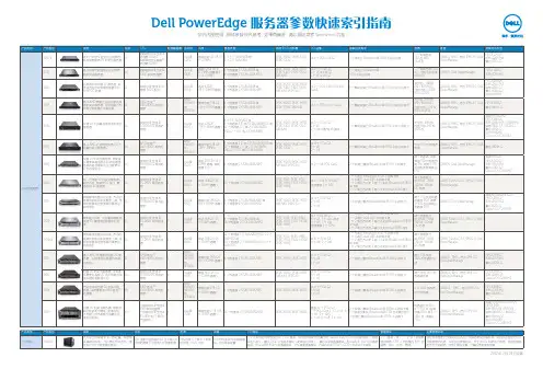
一、命名规则戴尔服务器产品主要划分为三大系列,服务器的命名规则是将服务器的种类作为起始字母:“R”代表机架式服务器;“T”代表塔式服务器;“M”代表模块化或者刀片式服务器。
紧随首字母之后的第一个数字代表系统中的插槽数量,其中1-4代表一个插槽,5-8代表两个插槽,9代表4个插槽;接下来的数字代表服务器属于第几代产品,0代表第一代,1代表第二代;最后一个数字代表服务器处理器类型,0代表英特尔处理器;5代表AMD处理器。
现在可以任意选择几款戴尔的服务器产品,并根据以上的命名规则来解读产品的特点和性能,比如PowerEdgeR200,该产品为机架式服务器产品中的第一代产品,选用的是英特尔处理器,并有一个处理器插槽,属于戴尔入门级机架式服务器产品。
再如PowerEdgeT710,通过名字可知该产品为戴尔的塔式服务器,有两个处理器插槽,属于戴尔的新一代即第二代产品,选用的也是英特尔处理器。
除此之外,戴尔服务器产品中还有少部分个别服务器产品并未按照以上规则命名,如PowerEdge2970、PowerEdge2900III等,用户可适当关注。

Dell PowerEdge RAID Controller (PERC) S100,PERC S300用户指南注、小心和警告注:“注”表示可以帮助您更好地使用计算机的重要信息。
小心:“小心”表示如果不遵循说明,就有可能损坏硬件或导致数据丢失。
警告:“警告”表示可能会导致财产损失、人身伤害甚至死亡。
____________________本文件的信息如有更改,恕不另行通知。
© 2008—2011 Dell Inc. 版权所有。
未经 Dell Inc. 书面许可,严禁以任何形式复制这些材料。
本文中使用的商标:Dell™、DELL 徽标、PowerEdge™ 和 OpenManage™ 都属于 Dell Inc 的商标。
Intel™ 是 Intel 公司在美国和其他国家(地区)的注册商标。
AMD®是 Advanced Micro Devices, Inc. 的注册商标,而 AMD Opteron™、AMD Phenom™ 和 AMD Sempron™ 是Advanced Micro Devices, Inc. 的商标。
Microsoft®、Windows®和 Windows Server®是 Microsoft 公司在美国和/或其他国家(地区)的商标或注册商标。
本文件中述及的其它商标和商品名称是指拥有相应标记和名称的公司或其制造的产品。
Dell Inc. 对不属于自己的商标和商品名称不拥有任何所有权。
型号:UCS61、UCS602011 年 2 月修订版 A01目录1警告:安全说明 (7)安全:一般信息 (7)安全:在系统内部操作 (8)防止静电放电 (8)2概述 (9)简介 (9)一般信息、预期使用者和使用的先决条件 (9)相关文档 (10)PERC S100 适配器或 PERC S300 适配器说明 (10)关于 RAID (15)RAID 术语 (16)3功能 (19)一般功能 (19)规格 (26)4硬件安装 (29)开始之前 (29)一般注意事项 (29)安装 PERC S300 适配器 (29)目录3将物理磁盘连接到 PERC S300 适配器 (33)完成硬件安装 (33)5安装驱动程序 (35)安装 Microsoft Windows 驱动程序 (35)6RAID 配置和管理 (43)使用 PERC 虚拟磁盘管理公用程序配置控制器 (43)7故障排除 (55)系统启动故障 (55)警告消息:Dell Inc. PERC S100 适配器或Dell Inc. PERC S300 适配器 BIOS 屏幕 (57)与虚拟磁盘相关的错误 (63)与物理磁盘相关的错误 (67)8附录 A (69)控制器规格 (69)控制器任务 (70)物理磁盘任务 (70)虚拟磁盘任务 (71)支持的 RAID 级别 (71)虚拟磁盘规格 (72)4目录9附录 B (73)RAID 技术 - 了解磁盘阵列和虚拟磁盘 (73)10附录 C (81)管制通告 (81)FCC 通告(仅限于美国) (82)加拿大工业部通告(仅限于加拿大) (83)CE 通告(欧盟) (83)CE 标记通告 (85)11附录 D (87)联系 Dell (87)索引 (89)词汇表 (93)目录56目录警告:安全说明7警告:安全说明遵循以下安全原则有助于确保您的人身安全,并防止您的系统和工作环境受到潜在的损害。
戴尔PowerEdge R610双路1U机架服务器评测报告【IT168评测中心】2009年4月2日,戴尔(DELL)公司在北京推出了5款基于全新英特尔至强5500系列处理器的第11代PowerEdge服务器,包括半高刀片式M610和全高刀片式M710、1U机架式R610、2U机架式R710和以及塔式T610服务器。
戴尔表示,在未来几个月内,戴尔还将推出更多双路产品,包括T710、R410与T410。
DELL第11代服务器4月2日发布会现场在稍后举行的一个服务器产品体验会上,DELL专门面向评测媒体介绍了DELL的最新一代服务器,戴尔中国服务器高级产品经理赵永琳向我们介绍了戴尔的新产品,“第11代PowerEdge服务器堪称戴尔历史上性能最强大的产品线,也是最安静和最漂亮的服务器。
”其特点主要表现在:内嵌Hypervisor,方便用户部署虚拟化软件,同时通过更大的内存和更多的I/O来提高虚拟化的性能和效率,用户通过虚拟化可以减少物理机数量,同时简化管理;通过采用高转换效率的电源、基于策略的电源散热控制,可以实现最高的每瓦特性能;集成内置管理模块,简化系统部署和安装时间,让用户把精力放到业务创新中去;外观上也是最漂亮的一代产品,获得了德国iF产品设计大奖,同时采用了低转速、大流量的风扇,使其成为戴尔历史上最安静的服务器。
因此,这此服务器可以通过进一步简化数据中心的操作、提高性能和能效并降低总体拥有成本,从而帮助企业用最低的成本获得最大的收益。
”DELL也很快在五月初向我们提供了第十一代PowerEdge服务器的样品:R610,从前面可知,这是一款1U机架式服务器产品。
由于在测试过程中由于发生了一些问题,因此本文出现有些拖延。
出了什么问题呢?请看后面分解。
DELL PowerEdge R610服务器作为最新一代的服务器,代数变迁的原因之一在于架构上的大变动。
以目前推出的Intel 架构型号为例(第十一代PowerEdge会有AMD架构的型号):它和上一代的明显差异就在于新一代PowerEdge采用了Nehalem架构,基于Nehalem-EP处理器和Tylersburg-EP芯片组。
Dell Precision 工作站 T3610用户手册管制型号: D01T管制类型: D01T004注、小心和警告注: “注”表示可以帮助您更好地使用计算机的重要信息。
小心: “小心”表示可能会损坏硬件或导致数据丢失,并说明如何避免此类问题。
警告: “警告”表示可能会造成财产损失、人身伤害甚至死亡。
版权所有© 2014 Dell Inc. 保留所有权利。
本产品受美国、国际版权和知识产权法律保护。
Dell™和 Dell 徽标是 Dell Inc. 在美国和 / 或其他管辖区域的商标。
所有此处提及的其他商标和产品名称可能是其各自所属公司的商标。
2014 – 03Rev. A01目录1 拆装计算机 (5)拆装计算机内部组件之前 (5)关闭计算机电源 (6)拆装计算机内部组件之后 (6)2 卸下和安装组件 (7)建议工具 (7)系统概览 (7)卸下电源设备 (PSU) (8)安装电源设备 (PSU) (8)卸下主机盖 (9)安装主机盖 (10)卸下 PSU 卡 (10)安装 PSU 卡 (12)卸下前挡板 (12)安装前挡板 (13)卸下光盘驱动器 (13)安装光盘驱动器 (16)卸下硬盘驱动器 (16)安装硬盘驱动器 (17)卸下扬声器 (17)安装扬声器 (18)安装热感器 (18)卸下热感器 (19)卸下输入/输出 (I/O) 面板 (19)安装输入/输出(I/O)面板 (21)拆下通风管 (21)安装通风管 (21)卸下内存模块 (22)安装内存模块 (22)取出币形电池 (22)安装币形电池 (23)卸下系统风扇 (23)安装系统风扇 (28)卸下散热器 (28)安装散热器 (28)卸下散热器风扇 (29)安装散热器风扇 (29)卸下处理器 (29)安装处理器 (30)卸下系统板 (31)安装系统板 (32)系统板组件 (33)3 附加信息 (35)内存模块指导原则 (35)电源设备 (PSU) 锁定 (35)4 系统设置程序 (37)引导顺序 (37)导航键 (37)系统设置程序选项 (38)更新 BIOS (44)系统密码和设置密码 (45)设定系统密码和设置密码 (45)删除或更改现有系统密码和/或设置密码 (46)禁用系统密码 (46)5 Diagnostics(诊断程序) (49)增强型预引导系统评估 (ePSA) 诊断程序 (49)6 排除计算机故障 (51)诊断 LED (51)错误消息 (53)不会使计算机停机的错误 (53)使计算机软停机的错误 (53)7 技术规格 (55)8 联系 Dell (63)1拆装计算机拆装计算机内部组件之前遵循以下安全原则有助于防止您的计算机受到潜在损坏,并有助于确保您的人身安全。
自查模板干塘子光伏电站电力监控系统安全防护自查报告一、电力监控系统安全防护工作开展情况1、安全防护运维和管理人员责任落实情况:组织机构和专责人员公司严格按照制定的《电力安全信息管理制度》中要求落实网络安全责任制,制定了以公司电力安全运行部经理为主管领导的管理机构,各值工作人员均严格按照制度职责要求做好相关工作。
2、安全防护运行管理落实情况:日常运行和应急预案及演练公司编制了《生产调度通信系统故障处置方案》,定期进行演练与培训。
运行值班人员每天对通信设备进行2次巡视检查并记录(2次/天),24小时对各监控系统进行监视。
特殊情况下,增加电力通信设备的特巡工作。
3、防护管理制度体系建立情况公司已制定了《电力安全信息管理制度》、《电力二次系统安全防护处置方案》、《生产调度通信系统故障处置方案》以防止公司二次安全防护系统故障突发事件,避免或最大程度地减轻二次安全防护系统故障造成的损失。
4、防护工作现状电站已按照《电力监控系统安全防护规定》识别区分生产控制区和信息管理区,生产控制区根据云南电网公司制定的电力监控系统安全防护方案执行到位,与电网调度联络使用专用通讯设备、专用光纤进行。
电站电力生产控制区与信息管理控制区之间联络只有光功率预测系统需要数据并连接至外网,生产控制区与光功率预测系统联络使用了由北京科东电力控制系统有限公司生产的网络安全隔离设备(StoneWall-2000)反向型防护措施,其它未有物理联络,避免了数据泄露及系统被控情况。
信息管理区与外网的连接统一由集团公司发放山石网科安全网关、深信服上网行为管理、深信服广域网加速安全设备进行上网,宾川公司已严格按照要求将设备安装到位,从技术层面上加强了公司信息管理区的网络安全。
本单位电力监控系统配置情况干塘子光伏电站单位共有5套电力监控系统,其中四级系统0套,三级系统0套,二级系统5套。
电力二次系统等级保护安全测评(安全评估)工作开展情况。
二、自查情况通过自查,共发现非常严重问题0项,严重问题1项,一般问题0项。