DMK2790-000LF中文资料
- 格式:pdf
- 大小:98.44 KB
- 文档页数:4

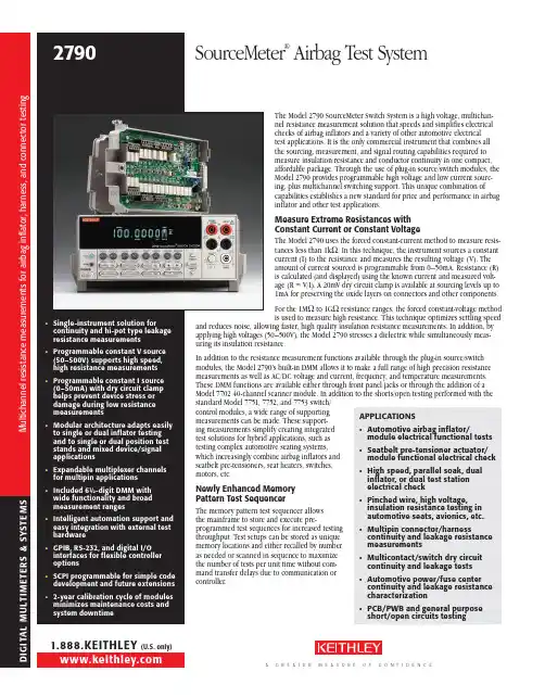
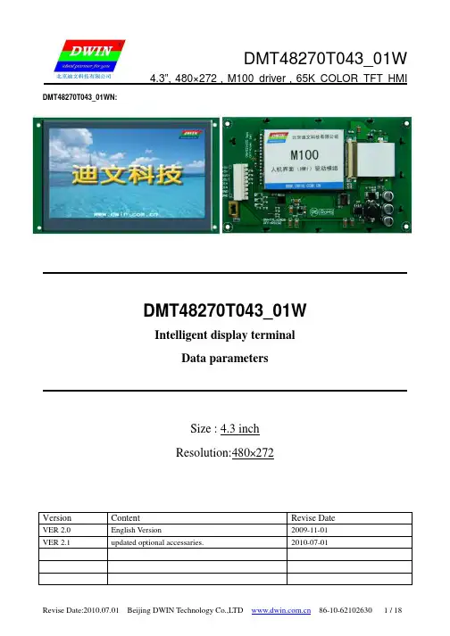
The Model 2790 S ourceMeter Switch System is a high voltage, multichan-nel resistance measurement solution that speeds and simplifies electricalchecks of airbag inflators and a variety of other automotive electricaltest applications. It is the only commercial instrument that combines allthe sourcing, measurement, and signal routing capabilities required tomeasure insulation resistance and conductor continuity in one compact,affordable package. Through the use of plug-in source/switch modules, theModel 2790 provides programmable high voltage and low current sourc-ing, plus multichannel switching support. This unique combination ofcapabilities establishes a new standard for price and performance in airbaginflator and other test applications.Measure Extreme Resistances withConstant Current or Constant VoltageThe Model 2790 uses the forced constant-current method to measure resis-tances less than 1kΩ. In this technique, the instrument sources a constantcurrent (I) to the resistance and measures the resulting voltage (V). Theamount of current sourced is programmable from 0–50mA. Resistance (R)is calculated (and displayed) using the known current and measured volt-age (R = V/I). A 20mV dry circuit clamp is available at sourcing levels up to1mA for preserving the oxide layers on connectors and other c omponents.For the 1MΩ to 1GΩ resistance ranges, the forced constant-voltage methodis used to measure high resistance. This technique optimizes settling speedAPPLICATIONS• Automotive airbag inflator/module electrical functional tests• Seatbelt pre-tensioner actuator/module functional electrical check• High speed, parallel soak, dualinflator, or dual test stationelectrical check• Pinched wire, high voltage,insulation resistance testing inautomotive seats, avionics, etc.• Multipin connector/harnesscontinuity and leakage resistancemeasurements• Multicontact/switch dry circuitcontinuity and leakage tests• Automotive power/fuse centercontinuity and leakage resistancecharacterization• PCB/PWB and general purposeshort/open circuits testing1.888.KEITHLEY (U.S. only)1.888.KEITHLEY (U.S. only)G I T A L M U L T I M E T E R S & S Y S T E M S Match the System Configuration to the ApplicationThe Model 2790 is available in a variety of configurations to match specific application requirements:• The Model 2790-H is a single-module system designed for both low current and high voltage ohms (10M Ω to 1G Ω) applications. This “base” system provides all the capabilities needed for electrical testing of either single- or dual-stage inflators in single position test stands (for example, test stands that test only one single- or dual-stage airbag at a time).• The Model 2790-A , which is similar to the Model 2790-H, enables high voltage ohms measure-ments down to 1M Ω.• The Model 2790-HH is configured for applications that require parallel testing or high voltage “soaking.” Like the Model 2790-H, it is designed for both low current and high voltage ohms appli-cations and can test either single- or dual-stage inflators. However, with two plug-in modules, it also has the capacity to test two inflators at once, maximizing test throughput.• The Model 2790-HL is designed for applications where it is preferable to segregate high voltage sourcing/ohms measurement and low current sourcing/ohms measurement into two separate modules. This design was developed for use in combination testing applications, such as inflator electrical checks of safety steering wheel or seat assemblies that also include switch or other ancil-lary device tests.• The Model 2790-L is configured for low voltage source/ohms-only measurement applications, such as continuity-only testing of side/seat airbags and seatbelt pre-tensioners or other program-mable I-source resistance applications in which high voltage resistance testing is not required but precise control of source current is.• With the addition of a Model 7702 40-channel differential multiplexer module (part of the Integra family of switch/measure solutions), the Model 2790-A, -H, or -L + Model 7702 opens the door to higher channel count applications, such as hi-pot/continuity testing of connectors, harnesses, and power distribution devices up to 500V (internally sourced) up to 40 channels.Broad Range of Measurement CapabilitiesThe Model 2790’s built-in DMM can make a wide variety of general purpose measurements:• DC voltage measurements from 0.1µV to 1000V • AC voltage measurements from 0.1µV to 750V • DC current measurements from 10nA to 3A • AC current measurements from 1µA to 3A• 2-wire resistance measurements from 100µΩ to 120M Ω• 4-wire resistance measurements from 100µΩ to 120M Ω• Frequency measurements from 3Hz to 500kHz • Period measurements from 333ms to 2µs• Temperature measurements from –200°C to 630°C (thermistors and 4-wire RTDs)Additional features of the Model 2790 mainframe include:• Setup storage—Up to four instrument setups can be saved and recalled.• Offset-compensated ohms—A two-measurement process for 4-wire ohms to cancel the effects of thermoelectric EMFs. Available for the 100Ω, 1k Ω, and 10k Ω ranges.• Math—m/X+b, mX+b, percent, and four special math functions provide convenient manipulation of raw readings.• Relative—Null offsets establish baseline values.• Ratio and channel average—Ratio and average calculations for two switching module channels (7702).• Buffer—Store up to 55,000 readings in the internal buffer.• Limits—Two sets of high and low reading limits to test devices.• Digital I/O port—Five digital limit test output lines to control external circuitry. An external trigger input can also be accessed at this port.• Trigger Link—Separate connector with input and output signals.• Monitor—The Model 2790 can monitor a selected channel. A scan can be triggered to start when the monitor detects that a reading limit has been reached (7702).• Remote interface—Model 2790 can be controlled using the IEEE-488 interface (GPIB) or theRS-232 interface.M u l t i c h a n n e l r e s i s t a n c e m e a s u r e m e n t s f o r a i r b a g i n f l a t o r , h a r n e s s , a n d c o n n e c t o r t e s t i n gExample Application – Dual Stage Airbag Inflator Testing–One or TwoExample Application – 40-channel Wiring Harness TestingModel 2790 Benefits• High functional integration—Sourcing, measurement, and signal routing functions are tightly integrated in one compact enclosure. This high level of integration helps system integrators save rack space, minimize the time needed for system configuration and maintenance, and improve test throughput without sacrificing system accuracy.• Enhanced device protection—Compared to higher powered alternatives, the Model 2790’s inherently lower power sources minimize the possibility of damaging sensitive devices under test through accidental overpowering. Automatic cold switching and active cable discharge circuitry reduce the chances for device damage still further, while the high precision DMM and A/D converter ensure high resolution and measurement accuracy.• Reliability—The design of the Model 2790 is based on a proven Keithley technology platform. With a two-year calibration cycle for the module functions, it requires minimal maintenance over the life of the production test line. Its modular mainframe and plug-ins architecture makes module verification and calibration fast and convenient, simply by exchanging modules.• Value—In addition to being a complete solution for airbag inflator testing and related applications, the Model 2790’s fully functional, 6½-digit DMM supports a wide variety of general purpose DC and AC measurements.Three source/switch plug-in mod-ules provide the Model 2790 with programmable high voltage and low current sources, connection switching, and signal conditioning circuitry. Mainframe SpecificationsRefer to the Model 2700 specifications on page 253.Key Module Specifications*Refer to module specifications on page 257.SYSTEM THROUGHPUTHIGH OHMS: 13 rdgs/s.LOW OHMS: 9 rdgs/s.* The Model 7751, 7752, and 7753 plug-in modules have a two-year calibration interval; mainframe-only functions have a one-year calibration interval (max). System warranty period is one year.1.888.KEITHLEY (U.S. only)1.888.KEITHLEY (U.S. only)G I T A L M U L T I M E T E R S & S Y S T E M S 7751/7752/7753 SOURCE/SWITCH MODULE SPECIFICATIONS2790 RESISTANCE MODE SPECIFICATIONS WITH CARDS 2, 3CURRENT MEASURE INPUT (7751/7753 Only)RANGE: 7751: 0–50µA. 7753: 0–500µA.ACCURACY: 7751: ±(0.5% of reading + 6nA) (2 year specification). 7753: ±(0.5% of reading + 60nA) (2 year specification).TEMPERATURE COEFFICIENT (0–18°C & 28–40°C): ±(0.02%+0.5nA)/°C.VOLTAGE BURDEN: <1mV.SWITCHING CAPABILITIES (Bank 1–Bank 4)4 CHANNELS: 1 Form A switch.8 CHANNELS: Four 4-pole or eight 2-pole signals into DMM or I/V converter.CONTACT CHECK: 4-wire contact check through internal DMM.RELAY TYPE: Latching electromechanical.ACTUATION TIME: <3ms.CONTACT LIFE (typical): >106 operations at maximum source level. >108 operations cold switching.CONTACT RESISTANCE: <1Ω at end of contact life.CONTACT POTENTIAL: <±2µV typical per contact pair, ±3µV max.CONNECTOR TYPE: Plugable screw terminal, #22 AWG wire size.ISOLATION BETWEEN ANY TWO TERMINALS 1: >1G Ω, <100pF.ISOLATION BETWEEN TERMINALS AND EARTH 1: >1G Ω, <200pF.ISOLATION BETWEEN CHANNEL GROUPS 1: >500G Ω, <100pF.EXTERNAL COMMON MODE VOLTAGE: 42V between any terminal and chassis. (Connect no external sources.)7751, 7752, OR 7753 MODULE NOTES1 Isolation for channels 1–12, only one channel closed at a time, or all channels open.2 See User's Manual for ohm specifications at sources other than those specified.3 All specifications valid for 1 NPLC ADC aperture setting.SYSTEM THROUGHPUT(Connect, source, measure, calculate)0.01 NPLC, FILTER OFF, OVER GPIB BUS: High Ohms (Source V): 13 rdgs/s 1. Low Ohms (Source I): 9 rdgs/s.1 NPLC, FILTER ON, OVER GPIB BUS: High Ohms (Source V): 11 rdgs/s 1. Low Ohms (Source I): 7 rdgs/s.SYSTEM THROUGHPUT NOTES1. Reset upon fixed V source level, no settling time.BASIC AIRBAG TEST SEQUENCE THROUGHPUT(Body Pin + Bridgewire Continuity = Shorting Clip + Insulation Resistance)0.55/0.97 seconds for single/dual stage DUT w/scan (sequential) memory patterns.1.0/2.0 seconds for single/dual stage DUT w/recall (random access) memory patterns.1.1/1.7 seconds for single/dual stage DUT discrete control w/GPIB I/O.(Sequence times are totals @ 1 line cycle integration for rated accuracy.)M o d e l 7751/7752/7753 s p e c i f i c a t i o n s1.888.KEITHLEY (U.S. only)775177527753。
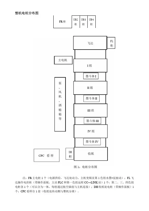
整机电柜分布图注:FR 主电柜1个(电源供给,飞达处动力,主机变频及第1色组水墨*昆驱动);FL 飞达操作电控柜(带操作面板,主站PLC 和第一色组远程CC —LINK 站)1个;第二、三、四色组电柜各1个(可以合为一体,每组通过航空插座与主机连接);DH 收纸处电柜(带操作面板)1个;CPC 看样台1套(收纸处传动侧与整机分离)。
整机动力系统图图2:动力系统图FR柜整机动力输入接口,完成各分电柜动力分配。
内置隔离控制变压器和开关电源提供整机控制电源220VAC.24VDC.10VDC、5VDC等电压等级检测执行器件电源,并将各电压等级电源分配至各分电柜。
控制柜外元件:◊主电机AEEF-FAC-(380VAC/18.5KW)东元电机◊空压机FF90L-40040380VAC 1.5KW◊真空输纸台吸风电机MLH6075Z380VAC250W◊飞达气泵IK380VAC 2.2KW◊主机给油泵HL-2202-410X220VAC25W◊第一色组水辑电机GM-SSYF-RH220VAC200W◊第一色组墨辑电机VFFP-22L-60-2002200VAC200WI/O统计:该电柜为动力分配及大功率元件控制柜,故不设安排PLC和远程I/O等。
所有元件动作控制信号均从FL柜输出引入此柜。
FL柜主控PLC完成整机状态检测和操作动作控制,与各分柜远程站进行通讯控制。
控制柜外元件:令编码器E6C3-AG5C。
前当规电磁铁令摆动叼牙电磁铁◊飞达离合器令前当规附近强制装置◊前规咬纸牙阀◊传墨电磁铁◊EPS电磁离合器。
主机调速电位器(按装位置在收纸侧)令电磁阀:一组印压SV、一组版压SV、一组靠版辑SV、靠版水辑SV、控水辑SV、桥程离合器SV、一组押版辑SV、版尾版夹SV、罩子SV、清洗耳恭听墨辑SV、清洗橡皮布SV令给纸台上下限位开关令给纸台上限传感器◊给纸台自动上升传感器令机械双张检测令橡皮布卡纸传感器◊左右前当规光纤传感器◊纸张左右超程传感器令超声波双张检测◊侧拉规光纤传感器令墨头罩子开关◊色组间罩子开关令水部罩子开关◊安全罩子开关令拉版界限开关令版错位调整小门限位开关◊版去脏装置传感器令桥*昆汽缸传感器令手盘车限位开关◊OMRON水位控制器61F-GP-N+底座PFU3-E或AUTONICS水位传感器RT18-8DNI/O统计:X:绝对编码器X20〜X27R28~X2F、(以上高速数字输入)主变频运转、跳闸、给纸台变频跳闸、飞达气泵热保护、真空输纸台吹风热保护、空压机热保护、主机给油泵热保护、给纸台上限、下限、上限传感器、自动上升传感器、机械双张、橡皮布卡纸、油浮开关、紧急停止、停止、紧急离压、运转准备、正点、反点、缓动、运转、高速、超声波双张、有纸、拉规、合压连动、飞达离合、飞达气阀、飞达/排纸气泵、全靠/全离、给纸台上升/下降、前挡规选择、拉规选择、拉规处理选择、强制合压、前当规传感器、超程、拉规传感器、罩子开关、备用.拉版限位、水/墨辑电机跳闸、版错位限位、版去脏传感器、桥*昆汽缸传感器、手盘车限位、水辑电机、靠版水粗、控水*昆、传墨辑、靠版墨辑、水*昆逆转、墨辑缓动、桥辑,罩子按钮开关、手动合压、摆墨辑、EPS操作、装版、卸版、水位检测、备用Y:前当规电磁铁、摆动叼牙电磁铁、主电机电磁接触器、主电机正转、反转、加速时间切换、EPS旋律选择、给纸台上升、下降、飞达气泵电机、真空输纸台吹风电机、空压机、主机给油泵、超声波双张灯、前当规检知灯、超程检知灯、拉规选取择灯、机械双张灯、给纸以外异常、电气双张检知灯、拉规检知灯、合压连动灯、飞达灯、飞达气泵灯、排纸气泵灯、靠版水辐灯、非常停止灯、锁定灯、运转灯、高速灯、蜂鸣器、计数、给纸阀、飞达离合SV、前当规强制装置、水辑正转、反转、墨辑正转、EPS罩子、靠版墨粗、水辑、控水辑、桥辐离合器、押版*昆、版尾版夹、清洗墨粗、橡皮布用SV、非常停止灯、锁定灯、水辑按钮灯、靠版水辑灯、控水辑灯、传墨辑灯、靠版辑灯、墨辑缓动灯、EPS罩子灯、桥程灯、备用。
一、概述本机以平压平高精度模切,拖料及切片由电脑控制,印刷两边及纵向由三只光电眼精确跟踪定位,模切、收废、切片或自动贴标机用的卷筒一次完成。
非常适合纸张不干胶商标、涤轮薄膜商标及镭射防伪商标的模切。
该机是柔性版印刷机、连续丝印机、凹版印刷机及防伪商标模切机最佳配套设备,是各商标印刷厂最理想高效率的机型。
(机器通电前务必要做好接地)二、主要技术参数a)模切速度20-120个/分b)模切宽度200-320㎜c)模切长度10-300㎜d)定位精度±0.15㎜e)电源电压220V±10﹪,50HZf)主机功率2kwg)外形尺寸 2.8(长)×0.95(宽)×1.5(高)mh)整机重量约1500kg三、电器触摸屏控制说明1、机器上电源后,打开控制箱上总电源开关,根据需要选择“中文”或“English”进入“工作”页面:2、(1)曲线,按△数字加大、按▽数字减小,设置曲线1~9,数字越大,拖料起步及停止越快,设置曲线数字越小,拖料起步及停止也越慢。
注:曲线数字设置过大会影响拖料精度,曲线数字设置过小会影响产量,为了保证拖料精度及产量曲线请设置在3~6。
(2)速度按△数字加大,按▽数字减小,设置速度从1~10数字越大拖料速度越快,设置数字越小拖料速度越慢,若模切后排废比较困难,速度请设置慢些。
(3)切片设置0为切刀不工作,设置1模切工作一次,切刀也工作一次,设置2模切工作二次,切刀工作一次,设置3模切工作三次,切刀工作一次……以此类推(4)长度设置模切拖料长度,按长度显示设置长度页:①按CTR清零键,②设置长度后,③再按ENT确认键,④按返回屏幕显示重新回到设置页。
(5)报警数设置报警数,按报警数显示设置报警数页:设置报警提示的数量。
①按CTR清零,②设置好数字,③再按ENT确认。
设置停机选择,总共有三种方式:1、报警不停机2、报警停机,延时开机3、报警停机若选择2报警停机,延时开机,要设置延时时间,设置需要延时的时间。
印刷机生产设施正常工况信息表参数名称
印刷机生产设施正常工况信息表一般包括以下参数名称:
1. 设备名称:印刷机型号或设备名称。
2. 设备编号:唯一识别码,用于标识设备。
3. 生产日期:设备的生产日期,用于追溯和质量管理。
4. 设备厂家:生产该设备的厂家名称。
5. 设备规格:包括设备的尺寸、重量、功率等主要规格参数。
6. 工作状态:描述设备的当前工作状态,如正常、待机、故障等。
7. 运行速度:设备的工作速度,以单位时间内处理的产品数量或米数表示。
8. 电源要求:设备所需的电源参数,如电压、频率、功率等。
9. 工作环境:设备的工作环境要求,包括温度、湿度、空气质量等。
10. 维护保养:设备的维护保养周期和方法,用于保证设备的正常运行。
11. 安全注意事项:设备的安全使用注意事项,以防止意外事故发生。
以上参数名称仅供参考,实际情况可能因设备型号和厂家而有所不同。
具体的参数应根据设备的说明书或相关标准来确定。
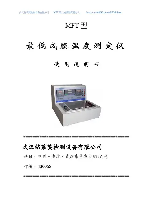
MFT型最低成膜温度测定仪使用说明书==============================================武汉格莱莫检测设备有限公司地址:中国·湖北·武汉市徐东大街51号邮编:430062==============================================一、产品简介聚合物乳液用作涂料、粘合剂、化纤织物、皮革、纸张等表面的处理剂时,它的成膜性是重要的技术指标之一。
研究者为了制造出更低成膜温度的新产品来,不断地改进其技术规范和配方。
因此检测出最低成膜温度(MFT)是此类涂料的重要指标,能够方便的测出MFT的理想仪器。
MFT型最低成膜温度测定仪是依据国家标准GB9267-2008而设计制造的,它是新一代漆膜测试仪,具有国内外传统测试仪器的诸多优点,又融合了台式、节能、超宽工作台、测温准确等优点于一体,成为同类仪器之佼佼者。
本手册中的所有图片和产品规格参数仅供参考,实际产品可能会略有差异,恕不另行通知。
二、主要参数★梯度板工作温度范围:冷端最低-7℃热端最高70℃★梯度板检测点:13个★梯度间隔:20mm★试验涂料槽:6条,长度240mm,宽度22mm深度0.25mm★巡检表显示:16点,其中1~13点为工作梯度温度,14点为仪器环境温度,15、16点为冷却水进出口温度★电源:220v50Hz交流宽电压(三相电源,接地良好)★冷却水源:普通市政供水★仪器外形:尺寸长520mm×宽520mm×高370mm(最大部分)★仪器重量:31Kg三、仪器特点★台式机设计,更节省空间。
★更先进的梯度板设计,以便更大的缩减体积。
★表面温度精确校准,配合温度标尺,确保测定数据准确可靠。
★自动断水保护系统。
★更宽的工作台,可以同时测量6组样品。
四、使用方法打开包装箱,(包装箱可以反复利用,请妥善保管,以便以后维修运输之用)检查一下有无破损短缺现象。
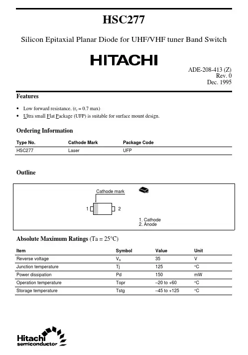
HSC277Silicon Epitaxial Planar Diode for UHF/VHF tuner Band SwitchADE-208-413 (Z)Rev. 0Dec. 1995 Features• Low forward resistance. (r f = 0.7max)• U l tra small F l at P a ckage (UFP) is suitable for surface mount design.Ordering InformationType No.Cathode Mark Package CodeHSC277Laser UFPOutlineAbsolute Maximum Ratings (Ta = 25°C)Item Symbol Value Unit35VReverse voltage VRJunction temperature Tj125°CPower dissipation Pd150mWOperation temperature Topr–20 to +60°CStorage temperature Tstg–45 to +125°CHSC2772Electrical Characteristics (Ta = 25°C)ItemSymbol Min Typ Max Unit Test Condition Reverse voltage V R 35——V I R = 10µA Reverse current I R ——50µA V R = 25V Forward voltage V F —— 1.0V I F = 10mA Capacitance C —— 1.2pF V R = 6V, f = 1MHz Forward resistancer f——0.7ΩI F = 2mA, f = 100MHzFig.1 Forward current Vs. Forward voltageHSC277Fig.2 Reverse current Vs. Reverse voltageFig.3 Capacitance Vs. Reverse voltage3HSC277Fig.4 Forward resistance Vs. Forward current 4HSC277 Package Dimensions5Cautions1.Hitachi neither warrants nor grants licenses of any rights of Hitachi’s or any third party’s patent,copyright, trademark, or other intellectual property rights for information contained in this document.Hitachi bears no responsibility for problems that may arise with third party’s rights, includingintellectual property rights, in connection with use of the information contained in this document.2.Products and product specifications may be subject to change without notice. Confirm that you have received the latest product standards or specifications before final design, purchase or use.3.Hitachi makes every attempt to ensure that its products are of high quality and reliability. However,contact Hitachi’s sales office before using the product in an application that demands especially high quality and reliability or where its failure or malfunction may directly threaten human life or cause risk of bodily injury, such as aerospace, aeronautics, nuclear power, combustion control, transportation,traffic, safety equipment or medical equipment for life support.4.Design your application so that the product is used within the ranges guaranteed by Hitachi particularly for maximum rating, operating supply voltage range, heat radiation characteristics, installationconditions and other characteristics. Hitachi bears no responsibility for failure or damage when used beyond the guaranteed ranges. Even within the guaranteed ranges, consider normally foreseeable failure rates or failure modes in semiconductor devices and employ systemic measures such as fail-safes, so that the equipment incorporating Hitachi product does not cause bodily injury, fire or other consequential damage due to operation of the Hitachi product.5.This product is not designed to be radiation resistant.6.No one is permitted to reproduce or duplicate, in any form, the whole or part of this document without written approval from Hitachi.7.Contact Hitachi’s sales office for any questions regarding this document or Hitachi semiconductor products.Hitachi, Ltd.Semiconductor & Integrated Circuits.Nippon Bldg., 2-6-2, Ohte-machi, Chiyoda-ku, Tokyo 100-0004, Japan Tel: Tokyo (03) 3270-2111 Fax: (03) 3270-5109Copyright ' Hitachi, Ltd., 1999. All rights reserved. Printed in Japan.Hitachi Asia Pte. Ltd.16 Collyer Quay #20-00Hitachi TowerSingapore 049318Tel: 535-2100Fax: 535-1533URLNorthAmerica : http:/Europe : /hel/ecg Asia (Singapore): .sg/grp3/sicd/index.htm Asia (Taiwan): /E/Product/SICD_Frame.htm Asia (HongKong): /eng/bo/grp3/index.htm Japan : http://www.hitachi.co.jp/Sicd/indx.htmHitachi Asia Ltd.Taipei Branch Office3F, Hung Kuo Building. No.167, Tun-Hwa North Road, Taipei (105)Tel: <886> (2) 2718-3666Fax: <886> (2) 2718-8180Hitachi Asia (Hong Kong) Ltd.Group III (Electronic Components)7/F., North Tower, World Finance Centre,Harbour City, Canton Road, Tsim Sha Tsui,Kowloon, Hong Kong Tel: <852> (2) 735 9218Fax: <852> (2) 730 0281 Telex: 40815 HITEC HXHitachi Europe Ltd.Electronic Components Group.Whitebrook ParkLower Cookham Road MaidenheadBerkshire SL6 8YA, United Kingdom Tel: <44> (1628) 585000Fax: <44> (1628) 778322Hitachi Europe GmbHElectronic components Group Dornacher Stra§e 3D-85622 Feldkirchen, Munich GermanyTel: <49> (89) 9 9180-0Fax: <49> (89) 9 29 30 00Hitachi Semiconductor (America) Inc.179 East Tasman Drive,San Jose,CA 95134 Tel: <1> (408) 433-1990Fax: <1>(408) 433-0223For further information write to:。
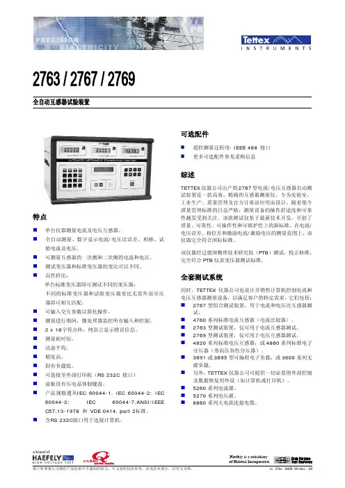
2763 / 2767 / 2769全自动互感器试验装置特点⏹ 单台仪器测量电流及电压互感器。
⏹ 全自动测量、数字显示电流/电压比误差、相移、试验电流及电压。
⏹ 可测量互感器的一次侧和二次侧的电流和电压。
⏹ 测试变压器和标准变压器的变比可以不同。
⏹高性价比:单台标准变压器即可测试不同的变压器;不同的标准变压器和试验变压器变比无需外部分压器即可相互匹配。
⏹ 可输入交互参数以简化操作。
⏹ 测量进行期间,微处理器监控所有输入和控制。
⏹ 2 x 16字符点阵,纯语言显示错误信息。
⏹ 测量耗时短。
⏹ 动态平均。
⏹ 精度高。
⏹ 固有负载低。
⏹ 可连接至外部打印机(RS 232C 接口) ⏹ 前板设有压电晶体制键盘。
⏹产品规格遵从IEC 60044-1, IEC 60044-2; IEC 60044-3; IEC 60044-7,ANSI/IEEE C57.13-1978 和 VDE 0414, part 2标准。
⏹ 含RS 232C接口用于连接计算机。
可选配件⏹ 遥控测量过程用- IEEE 488 接口 ⏹更多可选配件参见采购信息综述TETTEX 仪器公司出产的2767型电流/电压互感器自动测试装置是一款高效、精确的互感器测量仪,专为实验室、工业生产、质量管理及官方计量站应用而设计。
随着现今质量管理标准的日益严格,测量设备的操作舒适度和可靠性越发受到关注。
该款测试仪基于最新技术开发,开创了质量、可靠性、可操作性和可维护性上的新标准,在电流/电压误差、相位差和激励电流/激励电压的测量范围上,该仪器完全符合国际标准。
该仪器经过德国物理技术研究院(PTB )测试,校正核准,完全符合PTB 仪表变压器测试标准。
全套测试系统同时,TETTEX 仪器公司也设计并销售计算机控制电流和电压互感器测量设备,以满足客户的特定需求,它们包括: ⏹ 2767型组合测试装置,用于电流和电压比互感器测试。
⏹ 4760系列标准电流互感器(电流比较器)。
冷裱机技术参数要求标准一、电源要求冷裱机应使用规定电压范围的电源,一般情况下应采用AC220V/50Hz的电源。
同时,应具备接地保护措施,确保设备在运行过程中的安全。
二、功率消耗冷裱机的功率消耗应符合设备运行的要求,同时应具备节能环保的特点。
在保证设备正常运行的前提下,应尽量降低功率消耗,减少能源的浪费。
三、尺寸要求冷裱机的尺寸应符合设备安装和使用的需求,根据实际使用环境和工作需求,合理设计设备的尺寸参数。
同时,设备的外观设计应简洁美观,方便用户操作和使用。
四、重量要求冷裱机的重量应考虑到设备的便携性和使用环境的限制。
在保证设备性能和稳定性的前提下,应尽量减轻设备的重量,方便用户搬运和操作。
五、冷裱膜类型冷裱机应具备适应多种冷裱膜的能力,包括但不限于PET、PVC等常见冷裱膜类型。
同时,设备应具备对不同冷裱膜的适用性测试和验证的能力,以确保设备在使用过程中的稳定性和可靠性。
六、工作温度冷裱机的工作温度应根据实际使用环境和使用需求进行合理设定。
在保证设备正常运行的前提下,应尽量降低工作温度,减少能源的浪费和设备的发热问题。
七、速度要求冷裱机的速度应满足生产和使用需求,根据不同的使用场景和生产需求,可调整设备的运行速度。
同时,设备应具备稳定的速度控制能力,以保证生产过程中的质量和效率。
八、安全保护冷裱机应具备完善的安全保护功能,包括但不限于过载保护、短路保护、漏电保护等。
在设备运行过程中,应能及时发现并处理异常情况,以保障设备和操作人员的安全。
此外,设备应设置操作安全提示和警告标志,确保操作人员在使用过程中遵循安全操作规程。
GaAs Flip Chip Schottky Diodes
Features
■Designed for High Volume Designs
■High Frequency (20–100 GHz)
■Exceeds Environmental Requirements for MIC & Hybrid Applications
■Designed for Low Junction Capacitance and Low Series Resistance
■Applications Include PCN Mixers and Circuits, As Well As Low Power, Fast Switching
■Low Parasitic Flip Chip Configuration Description
This new series of GaAs Schottky barrier diodes offer high performance at commercial market prices.They are designed for low junction capacitance, as well as low series resistance.Diodes are designed for MIC work (hard and soft substrates), but the leadless design eliminates the problems associated with mounting of beam lead diodes. Due to its rigid construction, it exceeds environmental requirements for MIC and hybrid applications.Diodes can be supplied on expandable film frame for high speed pick and place process.Standard packing will be in a waffle pack.Flexible conductive epoxy is the most effective method for circuitry attachments.Standard mounting temperatures should not exceed 175°C.Single - DMK2783-000, DMK2790-000
B
2.C T= junction capacitance plus 0.02 pF (overlay).
Histogram
V F 1 mA (mV)
680
700720740
N u m b e r o f O b s
05101520253035404550556065
Capacitance/Voltage Variation
Bias Voltage (V)
0.5 1.0 1.5 2.0 2.5 3.0 3.5 4.0 4.5 5.0
D e v i c e C a p a c i t a n c e (p F )
0.028
0.0320.0360.0400.0440.0480.0520.056
0.0600.0640.0680.0720.0760.080Histogram
R T 10 mA (Ω)
4.0 4.5
5.0 5.5
6.0
N u m b e r o f O b s
0112233445566778899110121132143154165x = 5.0 Histogram Capacitance 0 V (pF)0.055
0.0600.0650.070
N u m b e r o f O b s
0510152025303540455055
60Typical Parameter Distribution on Wafer
Spice Parameters (Per Junction)
I S R S T D C J 0E G V J B V I BV Amp Ωn S pF m eV eV X TI FC V A 0.5 E–12
4
1.05
1E–11
0.05
0.26
1.43
0.82
2
0.5
4.0
1E–05
Flexible Conductive Epoxy Mounting of Alpha Beamless Flip Chip Diodes – To Soft or Hard Substrate – As Plated
Deposit Conductive Epoxy
Cure Epoxy & DC Continuity Check
• Inspect for Adequate Epoxy Fillet
• Cure According to Mfg.Preferred Schedule.T ypically 110–150°C @ 60 Minutes, or 150°C, 4 Minutes for Snap-Cure Epoxies
1–2 mil height
Perform Die Attach
• Flip Device
• Align Bond Pads to Epoxy Dot (Alignment Marks Help)
• Use Even Pressure to Make Correct Connection
Suggested Setup Values For WEST-BOND Model 7200A Epoxy Die Bonder
Materials Epoxy
Microelectronic grade one component, solvent-free silver-filled, electrically conductive adhesive — example:Ablebond 8380 by Ablestick.Dispense Tube
WEST -BOND B-1831-1 with 9.5 mil I.D., or WEST -BOND B-1831-2 with 15.5 mil I.D.Other sizes available.Die Pickup Tool
SPT Part Number 2101-W625-CT -031 x 0.016 x 0.0075.Hole diameter 0.016" face diameter 0.031", O.D.0.625".Use vacuum pressure to pick and place chip.Adjustment Bond Force
35 grams at tool.Dispense Air 30 psi.
Dispense Time
To give diameter of dot required.Curing Time
Temperature
Time 250°C 10 min.130°C 20 min.100°C 60 min.85°C
120 min.
Outline Drawings
± 0.001 (0.025 mm) 540-012。