H3C IPV6之IBGP一级RR路由反射器典型组网配置案例
- 格式:docx
- 大小:237.68 KB
- 文档页数:10

H3C设备组网详细配置步骤(总7页)-CAL-FENGHAI.-(YICAI)-Company Onel-CAL-本页仅作为文档封面,使用请直接删除设备清单:设备名称 产品型号数量 配置单价 价格 核心路由器 H3C MSR 20-20 1 2 x 100M WAN 接口 6000 6000 核心三层交换机 H3C S3600-28TP-SI 1 24 x 100M+2 x 10/100/100M50005000 核心二层交换机 H3C S3100-26C-SI 1 24 x 10/100M 3000 3000 服务器 浪潮 NF190D2 2 E5405(2.00G)/12M/2G DDR2/73GSAS/1000M*2/单电源2003040060 客户机浪潮日升S300 PRSS300000062E2200 2.2G/1M/1G/160G SATA/集成显卡/17”纯平37007400网络拓朴:配置步骤:1.端口设置及端口捆绑1.1 在3L 和2L 上设置以下命令:(在三层交换机与二层交换机上配置) interface Ethernet 0/2 to Ethernet 0/3 speed 100 duplex full192.1 US ,0.174VlanIWl 132,1^0,0,2.24Vian 3工程部 网段:1S2.16S.3J0网关:192.168.3,1Vian 2市场部 同段:192/1SS 工J0 网关羲曦2.1组网需求:1,利用端口报绑技术实现高速上行醒路 2.利用GVRP 实现vlan 信息动态学习3,利用三层交换机实现Wan 间通讯4,实现三层交换机和路由器互连互通 5 .利用ACL 限制Vian 2访问Vian 3 6 .设置三层交换机的DHCP 服务器功能 7 .没置STP,实现防止广播风暴功能 8 .路由器上做NAT 实现内部主机上网 9,发布雕务器实现外离用户访问 发布地址:192.1684.5 4 123.1.1.2 192.1684.6 . 123.1.1.310 .实现网络设备远程faeln£噌理 11 .实现网络设备的安全设置S3600-28TP-SIVian 1网管网段:1遨1底力 网关:192.168.1.1port link-type trunkport trunk permit vlan all #link-aggregation Ethernet 0/2 to Ethernet 0/3 both 2.GVRP配置2.1在3L上和2L上设置system-view #gvrp/设备开启gvrp功能#interface ethernet 0/2 to ethernet 0/3gvrp/在trunk端口上开启gvrp3.VLAN设置3.1在3L上设置Vlan 2市场部#Vlan 3工程部#Vlan 4服务器3.2在2L上设置interface Ethernet 0/8Port access vlan 3#interface Ethernet 0/9Port access vlan 2#interface ethernet 0/4 to ethernet 0/5/3L上设置端口加服务器vlanPort access vlan 44.三层交换实现Vlan互通4.1在3L上设置interface vlan-interface 1/网管Vlanip address 192.168.1.1 255.255.255.0 undo shutdown#interface vlan-interface 2/市场Vlanip address 192.168.2.1 255.255.255.0 undo shutdown#interface vlan-interface 3/工程vlan ip address 192.168.3.1 255.255.255.0 undo shutdown #interface vlan-interface 4 /服务器vlanip address 192.168.4.1 255.255.255.0 undo shutdown5.三层交换机和路由器互通5.1在3L上设置Interface vlan-interface 100Ip address 192.168.0.2 255.255.255.0 Undo shutdown#Ip route-static 0.0.0.0 0.0.0.0 192.168.0.1/指向路由器的默认路由5.2在路由器上设置Interface Ethernet 0/0Ip address 192.168.0.1 255.255.255.0 Undo shutdown#Ip route-static 192.168.0.0 255.255.0.0/超网路由,指向所有vlan的回程路由#Ip route-static 0.0.0.0 0.0.0.0 123.1.1.4/指向ISP的默认路由器6.ACL限制vlan2和vlan3互访6.1在三层交换机上设置acl number 3000rule 0 denyip source 192.168.3.0 0.0.0.255 destination 192.168.2.0 0.0.0.255 rule 1 permitip6.2在vlan2的三层接口上设置Interface vlan-interface 2packet-filterinbound ip-group 30007.三层交换机做DHCP服务器7.1在3L上设置dhcp server ip-pool vlan2network 192.168.2.0 mask 255.255.255.0gateway-list 192.168.2.1domain-name dns-list 192.168.4.5dhcp server forbidden-ip 192.168.2.1 #dhcp server ip-pool vlan3network 192.168.3.0 mask 255.255.255.0gateway-list 192.168.3.1domain-name dns-list 192.168.4.5dhcp server forbidden-ip 192.168.3.17.2在3L的vlan2和vlan3三层接口上设置interface vlan-interface 2dhcp select global #interface vlan-interface 3dhcp select global8.STP设置8.1在3L上设置stp root primary # interface ethernet 0/10 to ethernet 0/24 set root-protenction /在指定端口启用根保护功能(根网桥上所有端口都是指定端口)8.2在2L上设置stp enable # interface ethernet 0/1 to Ethernet 0/24 stp disable /在交换机连PC端口关闭stp功能9.路由器做NAT9.1在路由器上设置acl number 2000/配置允许进行NAT转换的内网地址段/rule 0 permit source 192.168.0.0 0.0.255.255rule 1 deny#interface Ethernet0/1/外网接口/ip address 123.1.1.1 255.255.255.248nat outbound 2000#interface Ethernet0/0ip address 192.168.0.1 255.255.255.0/内网网关/#10.发布内网月艮务器10.1在路由器上设置nat server protocol tcp global 123.1.1.2 inside 192.168.4.5 nat server protocol tcp global 123.1.1.3 inside 192.168.4.611.网络设置telnet设置11.1在三层交换机和路由器上设置telnetuser-interface vty 0authentication-mode passwordset authentication password simple ly-benetuser privilege level 3protocol inbound telnetidle-timeout 611.2在2L上设置telnet和管理ip地址Interface vlan-interface 1Ip address 192.168.1.2 255.255.255.0Undo shutdown#user-interface vty 0authentication-mode passwordset authentication password simple ly-benetuser privilege level 3protocol inbound telnet idle-timeout 612.网络设备安全设置12.1关闭没有使用的端口Interface Ethernet 0/10 to Ethernet 0/24Undo shutdwon12.2设置console 口令user-interface aux 0authentication-mode passwordset authentication password simple ly-benetuser privilege level 3idle-timeout 512.3设置服务器IP,MAC和端口绑定System-viewAm user-bind ip-address 192.168.4.5 mac-address 00e0-fcab-cd11 interface e0/4 Am user-bind ip-address 192.168.4.6 mac-address 0000-0cab-cd12 interface e0/5。

操作手册 IP路由分册 IPv6 静态路由目录目录第1章 IPv6静态路由配置......................................................................................................1-11.1 IPv6静态路由简介.............................................................................................................1-11.1.1 IPv6静态路由属性及功能........................................................................................1-11.1.2 IPv6缺省路由..........................................................................................................1-11.2 配置IPv6静态路由.............................................................................................................1-21.2.1 配置准备..................................................................................................................1-21.2.2 配置IPv6静态路由...................................................................................................1-21.3 IPv6静态路由显示和维护..................................................................................................1-21.4 IPv6静态路由典型配置举例(路由应用).........................................................................1-31.5 IPv6静态路由典型配置举例(交换应用).........................................................................1-5本文中标有“请以实际情况为准”的描述,表示各型号对于此特性的支持情况可能不同,本节将对此进行说明。

典型配置举例1.5 PPP单向认证举例1.5.1 PAP1. 组网需求Router ARouter B之间用接口Serial2/1/0互连,要求如图1-3所示,Router A和进行认证。
Router B不需要对Router A用PAP方式认证Router B,组网图2.图1-3 配置PAP单向认证组网图3. 配置步骤(1) 配置Router A# 为Router B创建本地用户。
<RouterA> system-view[RouterA] local-user userb class network# 设置本地用户的密码。
[RouterA-luser-network-userb] password simple passb# 设置本地用户的服务类型为PPP。
[RouterA-luser-network-userb] service-type ppp[RouterA-luser-network-userb] quit# 配置接口封装的链路层协议为PPP(缺省情况下,接口封装的链路层协议为PPP,此步骤可选)。
[RouterA] interface serial 2/1/0[RouterA-Serial2/1/0] link-protocol ppp# 配置本地认证Router B的方式为PAP。
[RouterA-Serial2/1/0] ppp authentication-mode pap domain system# 配置接口的IP地址。
[RouterA-Serial2/1/0] ip address 200.1.1.1 16[RouterA-Serial2/1/0] quit# 在系统缺省的ISP域system下,配置PPP用户使用本地认证方案。
[RouterA] domain system[RouterA-isp-system] authentication ppp local(2) 配置Router B# 配置接口封装的链路层协议为PPP(缺省情况下,接口封装的链路层协议为PPP,此步骤可选)。

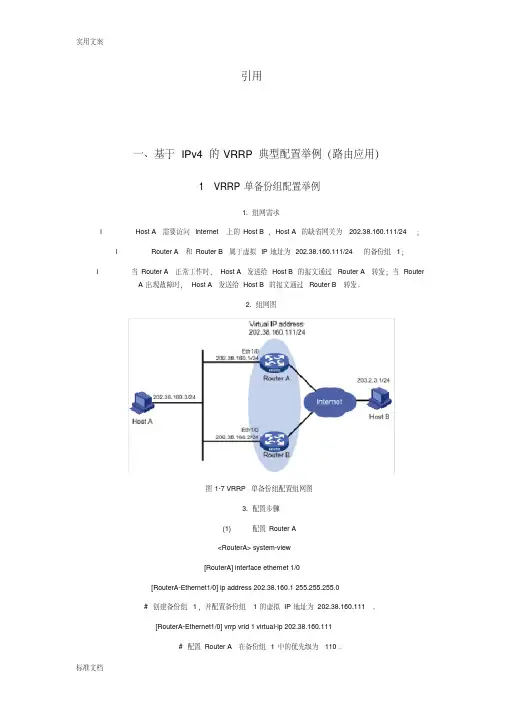
引用一、基于IPv4的VRRP典型配置举例(路由应用)1 VRRP单备份组配置举例1. 组网需求l Host A需要访问Internet上的Host B,Host A的缺省网关为202.38.160.111/24;l Router A和Router B属于虚拟IP地址为202.38.160.111/24的备份组1;l 当Router A正常工作时,Host A发送给Host B的报文通过Router A转发;当Router A出现故障时,Host A发送给Host B的报文通过Router B转发。
2. 组网图图1-7 VRRP单备份组配置组网图3. 配置步骤(1) 配置Router A<RouterA> system-view[RouterA] interface ethernet 1/0[RouterA-Ethernet1/0] ip address 202.38.160.1 255.255.255.0# 创建备份组1,并配置备份组1的虚拟IP地址为202.38.160.111。
[RouterA-Ethernet1/0] vrrp vrid 1 virtual-ip 202.38.160.111# 配置Router A在备份组1中的优先级为110。
[RouterA-Ethernet1/0] vrrp vrid 1 priority 110# 配置Router A工作在抢占方式,抢占延迟时间为5秒。
[RouterA-Ethernet1/0] vrrp vrid 1 preempt-mode timer delay 5(2) 配置Router B<RouterB> system-view[RouterB] interface ethernet 1/0[RouterB-Ethernet1/0] ip address 202.38.160.2 255.255.255.0# 创建备份组1,并配置备份组1的虚拟IP地址为202.38.160.111。
![[史上最详细]H3C路由器NAT典型配置案例](https://uimg.taocdn.com/882e4d6942323968011ca300a6c30c225801f060.webp)
H3C路由器NAT典型配置案列(史上最详细)神马CCIE,H3CIE,HCIE等网络工程师日常实施运维必备,你懂的。
1.11 NAT典型配置举例1.11.1 内网用户通过NAT地址访问外网(静态地址转换)1. 组网需求内部网络用户10.110.10.8/24使用外网地址202.38.1.100访问Internet。
2. 组网图图1-5 静态地址转换典型配置组网图3. 配置步骤# 按照组网图配置各接口的IP地址,具体配置过程略。
# 配置内网IP地址10.110.10.8到外网地址202.38.1.100之间的一对一静态地址转换映射。
<Router> system-view[Router] nat static outbound 10.110.10.8 202.38.1.100# 使配置的静态地址转换在接口GigabitEthernet1/2上生效。
[Router] interface gigabitethernet 1/2[Router-GigabitEthernet1/2] nat static enable[Router-GigabitEthernet1/2] quit4. 验证配置# 以上配置完成后,内网主机可以访问外网服务器。
通过查看如下显示信息,可以验证以上配置成功。
[Router] display nat staticStatic NAT mappings:There are 1 outbound static NAT mappings.IP-to-IP:Local IP : 10.110.10.8Global IP : 202.38.1.100Interfaces enabled with static NAT:There are 1 interfaces enabled with static NAT.Interface: GigabitEthernet1/2# 通过以下显示命令,可以看到Host访问某外网服务器时生成NAT会话信息。


IPv6 配置1.1IPv6基本配置首先在全局模式,开启ipv6单播转发Router(config)#ipv6 unicast-routing此后可以开启Cisco的快速转发Router(config)#ipv6 cef1.1.2 链路上启用ipv6对于一个节点而言,它需要给每个网络接口配置本地链路地址,还需要回环地址,所有节点多播地址,分配的可聚合全球单播地址,所用于每个单播和任意播地址的被请求节点多播地址以及主机所属的所有组的多播地址。
对于一个路由器,除此之外还需要所有路由器的多播地址,子网路由器的任意播地址以及其他任意播地址等。
路由器的配置如下:A:静态地址配置首先需要配置一个接口的链路地址Router(config-if)#ipv6 address FE80:0:0:0:2123:0136:0789:0abc link-local此后需要配置可聚合的全球单播地址Router(config-if)#ipv6 address 2001:090:0:1:0:0:0:1/64最后需要配置本地站点地址:Router(config-if)#ipv6 address FEC0:090:0:1:0:0:0:1/64B:回环地址配置和普通地址配置一样,仅需要在回环接口上配置ipv6接口地址Router(config)#interface loopback 0Router(config-if)#ipv6 address FEC0:090:0:1:0:0:0:1/128C:使用EUI-64配置可以使用EUI-64的方式配置ipv6地址。
EUI-64通过一种影射关系,例如某接口的MAC地址为0013.122.5678,EUI-64的编址方式为,在最中间的插入FFFE,例如该地址的EUI-64地址就为0013.12FF.FE2.5678。
EUI-64的配置方法如下:首先可以定义一个前缀ipv6 general-prefix prefix-name [ipv6-prefix/prefix-length]然后在接口上配置Ipv6 addreass prefix-name:ipD:配置前缀例如:Ipv6 general-prefix kaka 2001:090:0:1::/64Ipv6 address kaka::1/64E:使用无编号接口Ipv6 unnumberedF:仅启用ipv6Ipv6 enable1.1.3 修改接口MTUCisco路由器默认以太网和快速以太网的MTU值 1500,在某些情况下需要修改这些值,如下:Router(config-if )#ipv6 mtu 14921.2 NDP邻居发现协议IPv6不再执行地址解析协议(ARP)或反向地址解析协议(RARP),而以邻居发现协议中的相应功能代替。
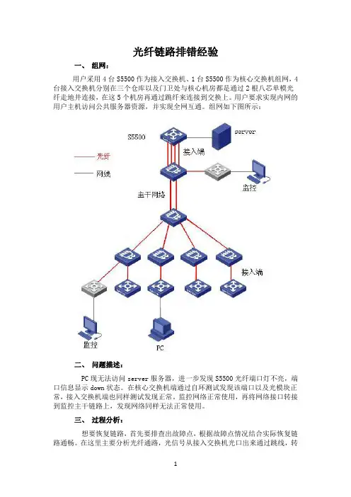
光纤链路排错经验一、组网:用户采用4台S5500作为接入交换机、1台S5500作为核心交换机组网,4台接入交换机分别在三个仓库以及门卫处与核心机房都是通过2根八芯单模光纤走地井连接,在这5个机房再通过跳纤来连接到交换上。
用户要求实现内网的用户主机访问公共服务器资源,并实现全网互通。
组网如下图所示:二、问题描述:PC现无法访问server服务器,进一步发现S5500光纤端口灯不亮,端口信息显示down状态。
在核心交换机端通过自环测试发现该端口以及光模块正常,接入交换机端也同样测试发现正常。
监控网络正常使用,再将网络接口转接到监控主干链路上,发现网络同样无法正常使用。
三、过程分析:想要恢复链路,首先要排查出故障点,根据故障点情况结合实际恢复链路通畅。
在这里主要分析光纤通路,光信号从接入交换机光口出来通过跳线,转接到主干光纤,然后再通过核心跳线转接到核心交换上。
由于该链路不通,首先要排除两端接口以及光模块问题,这里使用自环检测(如果是超远距离传输光纤线缆需要接光衰然后在自环,防止烧坏光模块)。
当检测完成发现无问题,再测试接入端的光纤跳纤:如果是多模光纤可以将一端接到多模光纤模块的tx口,检测对端是否有光;单模光纤如果没有光功率计可以使用光电笔检测(该方法只能检测出中间无断路,并不能检测出线路光衰较大的情况)。
最后再检测主线路部分,检测方式同跳线一样。
光路走向流程如图所示:四、解决方法:从上述的分析可以看出,只要保证了光信号一出一收两条路径都能正常就可以解决用户无法访问服务器的问题。
为了保证光路正常通路,最好的解决方法就是,通过使用光功率计来检测对端发射光在本端的光功率是否在光口可接受范围内。
由于用户组网使用了一些监控设备来接入该主干光缆,并且该光路现正常使用,通过将网络光纤转接到该监控主干光缆,发现网络光路仍然不通;并且两端端口自环检测正常。
由此可以判断出主要问题在两端的跳纤上。
如图所示:在没有光功率计并且客户业务又比较着急恢复的情况,可以先将两端的接入跳纤更换。

目录第1章 IPv6 BGP配置.............................................................................................................1-11.1 IPv6 BGP简介....................................................................................................................1-11.2 配置任务简介.....................................................................................................................1-21.3 配置IPv6 BGP的基本功能..................................................................................................1-31.3.1 配置准备..................................................................................................................1-31.3.2 配置IPv6对等体......................................................................................................1-31.3.3 配置IPv6 BGP发布本地IPv6路由............................................................................1-41.3.4 配置路由首选值.......................................................................................................1-41.3.5 配置IPv6 BGP连接所使用的本地接口.....................................................................1-51.3.6 配置非直接相连的邻居建立EBGP连接....................................................................1-51.3.7 配置对等体/对等体组的描述信息.............................................................................1-61.3.8 禁止与对等体/对等体组建立会话.............................................................................1-61.3.9 记录指定对等体/对等体组的会话状态和事件信息...................................................1-71.4 控制路由信息的发布与接收................................................................................................1-71.4.1 配置准备..................................................................................................................1-71.4.2 配置IPv6 BGP引入其他路由....................................................................................1-71.4.3 配置向对等体/对等体组发送缺省路由......................................................................1-81.4.4 配置路由信息的发布策略.........................................................................................1-81.4.5 配置路由信息的接收策略.........................................................................................1-91.4.6 配置IPv6 BGP与IGP路由同步...............................................................................1-101.4.7 配置路由衰减.........................................................................................................1-111.5 配置IPv6 BGP的路由属性................................................................................................1-111.5.1 配置准备................................................................................................................1-111.5.2 配置IPv6 BGP路由管理的优先级、缺省LOCAL_PREF及NEXT_HOP属性...............1-121.5.3 配置MED属性........................................................................................................1-121.5.4 配置AS_PATH属性...............................................................................................1-131.6 调整和优化IPv6 BGP网络................................................................................................1-141.6.1 配置准备................................................................................................................1-141.6.2 配置IPv6 BGP的时钟............................................................................................1-151.6.3 配置IPv6 BGP软复位............................................................................................1-151.6.4 配置最大等价路由的条数.......................................................................................1-161.7 组建大型IPv6 BGP网络...................................................................................................1-161.7.1 配置准备................................................................................................................1-171.7.2 配置IPv6 BGP对等体组.........................................................................................1-171.7.3 配置IPv6 BGP团体................................................................................................1-191.7.4 配置IPv6 BGP路由反射器.....................................................................................1-201.8 配置6PE..........................................................................................................................1-201.8.1 配置准备................................................................................................................1-211.8.2 配置6PE基本功能.................................................................................................1-211.8.3 配置6PE可选功能.................................................................................................1-22 1.9 IPv6 BGP显示和维护.......................................................................................................1-241.9.1 IPv6 BGP显示.......................................................................................................1-241.9.2 复位IPv6 BGP连接................................................................................................1-251.9.3 清除IPv6 BGP信息................................................................................................1-26 1.10 IPv6 BGP典型配置举例(路由应用)............................................................................1-261.10.1 IPv6 BGP基本配置..............................................................................................1-261.10.2 配置IPv6 BGP路由反射.......................................................................................1-291.10.3 配置6PE.............................................................................................................1-30 1.11 IPv6 BGP典型配置举例(交换应用)............................................................................1-351.11.1 IPv6 BGP基本配置..............................................................................................1-361.11.2 配置IPv6 BGP路由反射.......................................................................................1-38 1.12 IPv6 BGP常见错误配置举例..........................................................................................1-401.12.1 IPv6 BGP对等体关系不能建立............................................................................1-40本文中标有“请以实际情况为准”的描述,表示各型号对于此特性的支持情况可能不同,本节将对此进行说明。
H3C路由器设置负载分担模式VRRP应用示例负载分担模式VRRP(Virtual Router Redundancy Protocol)是一种常用的网络冗余技术,通过将多台路由器组成一个虚拟路由器来提供高可靠性和负载均衡的服务。
下面,我将为您提供一个关于H3C路由器设置负载分担模式VRRP应用示例的详细介绍。
假设我们有两台H3C路由器,分别为Router1和Router2,它们的IP 地址分别为192.168.0.1和192.168.0.2、我们将配置VRRP来实现这两台路由器之间的负载分担。
第一步,配置VRRP组在Router1上,输入以下指令:```[H3C] interface gigabitethernet 0/0/1[H3C-GigabitEthernet0/0/1] vrrp vrid 1 virtual-ip192.168.0.10[H3C-GigabitEthernet0/0/1] vrrp vrid 1 priority 110[H3C-GigabitEthernet0/0/1] vrrp vrid 1 preempt-mode[H3C-GigabitEthernet0/0/1] vrrp vrid 1 track interface gigabitethernet 0/0/2```在Router2上,输入以下指令:```[H3C] interface gigabitethernet 0/0/1[H3C-GigabitEthernet0/0/1] vrrp vrid 1 virtual-ip192.168.0.10[H3C-GigabitEthernet0/0/1] vrrp vrid 1 priority 100[H3C-GigabitEthernet0/0/1] vrrp vrid 1 preempt-mode[H3C-GigabitEthernet0/0/1] vrrp vrid 1 track interface gigabitethernet 0/0/2```在上述配置中,vrid表示VRRP组的ID,virtual-ip表示虚拟路由器的IP地址,priority表示路由器的优先级,preempt-mode表示该路由器具有抢占模式,track interface表示该路由器将监控另一台路由器的接口状态。
目录第1章 IPv6 MBGP配置..........................................................................................................1-11.1 IPv6 MBGP简介.................................................................................................................1-11.2 IPv6 MBGP配置任务简介..................................................................................................1-21.3 配置IPv6 MBGP的基本功能...............................................................................................1-21.3.1 配置准备..................................................................................................................1-21.3.2 配置IPv6 MBGP对等体...........................................................................................1-31.3.3 配置路由首选值.......................................................................................................1-31.4 控制路由信息的发布与接收................................................................................................1-41.4.1 配置准备..................................................................................................................1-41.4.2 配置IPv6 MBGP发布本地IPv6路由.........................................................................1-41.4.3 配置IPv6 MBGP引入其他路由.................................................................................1-51.4.4 配置向IPv6 MBGP对等体/对等体组发送缺省路由...................................................1-51.4.5 配置IPv6 MBGP路由信息的发布策略......................................................................1-61.4.6 配置IPv6 MBGP路由信息的接收策略......................................................................1-61.4.7 配置IPv6 MBGP路由衰减........................................................................................1-71.5 配置IPv6 MBGP的路由属性...............................................................................................1-81.5.1 配置准备..................................................................................................................1-81.5.2 配置IPv6 MBGP路由管理优先级.............................................................................1-81.5.3 配置本地优先级缺省值............................................................................................1-81.5.4 配置MED属性..........................................................................................................1-91.5.5 配置发布路由时将自身地址作为下一跳...................................................................1-91.5.6 配置AS_PATH属性...............................................................................................1-101.6 调整和优化IPv6 MBGP网络.............................................................................................1-101.6.1 配置准备................................................................................................................1-101.6.2 配置IPv6 MBGP软复位.........................................................................................1-101.6.3 配置最大等价路由的条数.......................................................................................1-121.7 配置大型IPv6 MBGP网络................................................................................................1-121.7.1 配置准备................................................................................................................1-121.7.2 配置IPv6 MBGP对等体组......................................................................................1-121.7.3 配置IPv6 MBGP团体.............................................................................................1-131.7.4 配置IPv6 MBGP路由反射器..................................................................................1-141.8 IPv6 MBGP显示和维护....................................................................................................1-151.8.1 IPv6 MBGP显示....................................................................................................1-151.8.2 复位IPv6 MBGP连接.............................................................................................1-161.8.3 清除IPv6 MBGP信息.............................................................................................1-161.9 IPv6 MBGP典型配置举例(路由应用)...........................................................................1-171.10 IPv6 MBGP典型配置举例(交换应用).........................................................................1-20本文中标有“请以实际情况为准”的描述,表示各型号对于此特性的支持情况可能不同,本节将对此进行说明。
通过在外网口配置nat基本就OK了,以下配置假设Ethernet0/0为局域网接口,Ethernet0/1为外网口。
1、配置内网接口(Ethernet0/0):[MSR20-20] interface Ethernet0/0[MSR20-20- Ethernet0/0]ip add 192.168.1.1 242、使用动态分配地址的方式为局域网中的PC分配地址[MSR20-20]dhcp server ip-pool 1[MSR20-20-dhcp-pool-1]network 192.168.1.0 24[MSR20-20-dhcp-pool-1]dns-list 202.96.134.133[MSR20-20-dhcp-pool-1] gateway-list 192.168.1.1三、配置步骤:设备和版本:MSR系列、version 5.20, R1508P02二、组网图:三、配置步骤:适用设备和版本:MSR系列、Version 5.20, Release 1508P022)要把一些固定的IP地址,如DNS服务器地址、域名服务器地址、WINS服务器地址禁止用于自动分配。
3)配置好地址池及相关服务器地址后,一定要在系统视图下使能DHCP服务功能。
MSR系列路由器GRE隧道基础配置关键字:MSR;GRE;隧道一、组网需求:Router A 、Router B两台路由器通过公网用GRE实现私网互通。
设备清单:MSR系列路由器2台二、组网图:四、配置关键点:1)两端的隧道地址要处于同一网段;2)不要忘记配置通过tunnel访问对方私网的路由。
L2TP 穿过NAT接入LNS功能配置关键字:MSR;L2TP;VPN;NAT;LNS一、组网需求:移动用户通过L2TP客户端软件接入LNS以访问总部内网,但LNS的地址为内网地址,需要通过NAT服务器后才能接入。
选择“连接到我的工作场所”,单击下一步选择“虚拟专用网络连接”,单击下一步输入连接名称“l2tp”,单击下一步选择“不拨初始连接”,单击下一步选择LNS的服务器地址1.1.1.1,单击下一步选择“不使用我的智能卡”,单击下一步单击完成,此时就会出现名为l2tp的连接,如下:单击属性按钮,修改连接属性,要与LNS端保持一致,如下:在属性栏里选择“安全”,选择“高级”->“设置”,如下:选择“允许这些协议”->“不加密的密码(PAP)(U)”,单击确定。
路由器反射器(RR)配置一、路由器基本配置R1>enableR1#conf tR1(config)#int lo 0R1(config-if)#ip add 1.1.1.1 255.255.255.0R1(config-if)#exitR1(config-if)#ip add 12.12.12.1 255.255.255.0 R1(config-if)#clock rate 128000R1(config-if)#no shutdownR1(config-if)#endR1#R2>enableR2#conf tR2(config)#int lo 0R2(config-if)#ip add 2.2.2.2 255.255.255.0R2(config-if)#exitR2(config)#int s0/0R2(config-if)#ip add 12.12.12.2 255.255.255.0 R2(config-if)#no shutdownR2(config-if)#exitR2(config)#int s0/1R2(config-if)#ip add 23.23.23.2 255.255.255.0 R2(config-if)#clock rate 128000R2(config-if)#no shutdownR2(config-if)#endR2#R3>enableR3#conf tR3(config)#int lo 0R3(config-if)#ip add 3.3.3.3 255.255.255.0R3(config-if)#exitR3(config)#int s0/0R3(config-if)#ip add 23.23.23.3 255.255.255.0 R3(config-if)#no shutdownR3(config-if)#exitR3(config)#int s0/1R3(config-if)#ip add 34.34.34.3 255.255.255.0 R3(config-if)#clock rate 128000R3(config-if)#no shutdownR3(config-if)#endR3#R4>enableR4#conf tR4(config)#int lo 0R4(config-if)#ip add 4.4.4.4 255.255.255.0R4(config-if)#exitR4(config-if)#ip add 34.34.34.4 255.255.255.0R4(config-if)#no shutdownR4(config-if)#exitR4(config)#exitR4#二、对路由器进行配置R1#conf tR1(config)#router eigrp 1R1(config-router)#net 1.1.1.0R1(config-router)#net 12.12.12.0R1(config-router)#no auto-summaryR1(config-router)#exitR1(config)#router bgp 100R1(config-router)#no synchronizationR1(config-router)#no auto-summaryR1(config-router)#bgp router-id 1.1.1.1R1(config-router)#neighbor 2.2.2.2 remote-as 100R1(config-router)#neighbor 2.2.2.2 update-source lo 0R1(config-router)#net 1.1.1.0 mask 255.255.255.0R1(config-router)#endR1#R2#conf tR2(config)#router eigrp 1R2(config-router)#net 12.12.12.0R2(config-router)#net 23.23.23.0R2(config-router)#net 2.2.2.0R2(config-router)#no auto-summaryR2(config-router)#exiR2(config)#router bgp 100R2(config-router)#no synchronizationR2(config-router)#no auto-summaryR2(config-router)#bgp router-id 2.2.2.2R2(config-router)#neighbor 1.1.1.1 remote-as 100R2(config-router)#neighbor 1.1.1.1 update-source lo 0R2(config-router)#neighbor 1.1.1.1 route-reflector-client //配置RR客户端R2(config-router)#neighbor 3.3.3.3 remote-as 100R2(config-router)#neighbor 3.3.3.3 update-source lo 0R2(config-router)#neighbor 3.3.3.3 route-reflector-clientR2(config-router)#endR2#R3#conf tR3(config)#router eigrp 1R3(config-router)#net 3.3.3.0R3(config-router)#net 23.23.23.0R3(config-router)#no auto-summaryR3(config-router)#exitR3(config)#router bgp 100R3(config-router)#no synchronizationR3(config-router)#no auto-summaryR3(config-router)#bgp router-id 3.3.3.3R3(config-router)#neighbor 2.2.2.2 remote-as 100R3(config-router)#neighbor 2.2.2.2 update-source lo 0R3(config-router)#neighbor 2.2.2.2 next-hop-selfR3(config-router)#neighbor 34.34.34.4 remote-as 200R3(config-router)#endR3#R4#conf tR4(config)#router bgp 200R4(config-router)#no synchronizationR4(config-router)#no auto-summaryR4(config-router)#bgp router-id 4.4.4.4R4(config-router)#neighbor 34.34.34.3 remote-as 100R4(config-router)#net 4.4.4.0 mask 255.255.255.0R4(config-router)#endR4#三、查看路由表R1#sh ip routeCodes: C - connected, S - static, R - RIP, M - mobile, B - BGPD - EIGRP, EX - EIGRP external, O - OSPF, IA - OSPF inter areaN1 - OSPF NSSA external type 1, N2 - OSPF NSSA external type 2E1 - OSPF external type 1, E2 - OSPF external type 2i - IS-IS, su - IS-IS summary, L1 - IS-IS level-1, L2 - IS-IS level-2ia - IS-IS inter area, * - candidate default, U - per-user static routeo - ODR, P - periodic downloaded static routeGateway of last resort is not set1.0.0.0/24 is subnetted, 1 subnetsC 1.1.1.0 is directly connected, Loopback02.0.0.0/24 is subnetted, 1 subnetsD 2.2.2.0 [90/2297856] via 12.12.12.2, 00:22:09, Serial0/03.0.0.0/24 is subnetted, 1 subnetsD 3.3.3.0 [90/2809856] via 12.12.12.2, 00:15:34, Serial0/04.0.0.0/24 is subnetted, 1 subnetsB 4.4.4.0 [200/0] via 3.3.3.3, 00:00:0423.0.0.0/24 is subnetted, 1 subnetsD 23.23.23.0 [90/2681856] via 12.12.12.2, 00:22:09, Serial0/012.0.0.0/24 is subnetted, 1 subnetsC 12.12.12.0 is directly connected, Serial0/0R1#R2#sh ip routeCodes: C - connected, S - static, R - RIP, M - mobile, B - BGPD - EIGRP, EX - EIGRP external, O - OSPF, IA - OSPF inter areaN1 - OSPF NSSA external type 1, N2 - OSPF NSSA external type 2E1 - OSPF external type 1, E2 - OSPF external type 2i - IS-IS, su - IS-IS summary, L1 - IS-IS level-1, L2 - IS-IS level-2ia - IS-IS inter area, * - candidate default, U - per-user static routeo - ODR, P - periodic downloaded static routeGateway of last resort is not set1.0.0.0/24 is subnetted, 1 subnetsD 1.1.1.0 [90/2297856] via 12.12.12.1, 00:14:16, Serial0/02.0.0.0/24 is subnetted, 1 subnetsC 2.2.2.0 is directly connected, Loopback03.0.0.0/24 is subnetted, 1 subnetsD 3.3.3.0 [90/2297856] via 23.23.23.3, 00:07:40, Serial0/14.0.0.0/24 is subnetted, 1 subnetsB 4.4.4.0 [200/0] via 3.3.3.3, 00:02:2523.0.0.0/24 is subnetted, 1 subnetsC 23.23.23.0 is directly connected, Serial0/112.0.0.0/24 is subnetted, 1 subnetsC 12.12.12.0 is directly connected, Serial0/0R2#R3#sh ip routeCodes: C - connected, S - static, R - RIP, M - mobile, B - BGPD - EIGRP, EX - EIGRP external, O - OSPF, IA - OSPF inter areaN1 - OSPF NSSA external type 1, N2 - OSPF NSSA external type 2E1 - OSPF external type 1, E2 - OSPF external type 2i - IS-IS, su - IS-IS summary, L1 - IS-IS level-1, L2 - IS-IS level-2ia - IS-IS inter area, * - candidate default, U - per-user static routeo - ODR, P - periodic downloaded static routeGateway of last resort is not set34.0.0.0/24 is subnetted, 1 subnetsC 34.34.34.0 is directly connected, Serial0/11.0.0.0/24 is subnetted, 1 subnetsD 1.1.1.0 [90/2809856] via 23.23.23.2, 00:07:48, Serial0/02.0.0.0/24 is subnetted, 1 subnetsD 2.2.2.0 [90/2297856] via 23.23.23.2, 00:07:48, Serial0/03.0.0.0/24 is subnetted, 1 subnetsC 3.3.3.0 is directly connected, Loopback04.0.0.0/24 is subnetted, 1 subnetsB 4.4.4.0 [20/0] via 34.34.34.4, 00:03:2623.0.0.0/24 is subnetted, 1 subnetsC 23.23.23.0 is directly connected, Serial0/012.0.0.0/24 is subnetted, 1 subnetsD 12.12.12.0 [90/2681856] via 23.23.23.2, 00:07:49, Serial0/0R3#R4#sh ip routeCodes: C - connected, S - static, R - RIP, M - mobile, B - BGPD - EIGRP, EX - EIGRP external, O - OSPF, IA - OSPF inter areaN1 - OSPF NSSA external type 1, N2 - OSPF NSSA external type 2E1 - OSPF external type 1, E2 - OSPF external type 2i - IS-IS, su - IS-IS summary, L1 - IS-IS level-1, L2 - IS-IS level-2ia - IS-IS inter area, * - candidate default, U - per-user static routeo - ODR, P - periodic downloaded static routeGateway of last resort is not set34.0.0.0/24 is subnetted, 1 subnetsC 34.34.34.0 is directly connected, Serial0/01.0.0.0/24 is subnetted, 1 subnetsB 1.1.1.0 [20/0] via 34.34.34.3, 00:00:504.0.0.0/24 is subnetted, 1 subnetsC 4.4.4.0 is directly connected, Loopback0R4#四、测试R2#sh ip bgp neiR2#sh ip bgp neighbors 1.1.1.1BGP neighbor is 1.1.1.1, remote AS 100, internal linkBGP version 4, remote router ID 1.1.1.1BGP state = Established, up for 00:04:40Last read 00:00:39, hold time is 180, keepalive interval is 60 seconds Neighbor capabilities:Route refresh: advertised and received(old & new)Address family IPv4 Unicast: advertised and receivedMessage statistics:InQ depth is 0OutQ depth is 0Sent RcvdOpens: 2 2Notifications: 0 0Updates: 2 2Keepalives: 29 29Route Refresh: 0 0Total: 33 33Default minimum time between advertisement runs is 5 secondsFor address family: IPv4 UnicastBGP table version 9, neighbor version 9/0Output queue sizes : 0 self, 0 replicatedIndex 2, Offset 0, Mask 0x4Route-Reflector Client2 update-group memberSent RcvdPrefix activity: ---- ----Prefixes Current: 1 1 (Consumes 48 bytes) Prefixes Total: 2 1Implicit Withdraw: 1 0Explicit Withdraw: 0 0Used as bestpath: n/a 1Used as multipath: n/a 0Outbound InboundLocal Policy Denied Prefixes: -------- -------Total: 0 0Number of NLRIs in the update sent: max 1, min 0Connections established 2; dropped 1Last reset 00:05:19, due to RR client config changeConnection state is ESTAB, I/O status: 1, unread input bytes: 0 Connection is ECN DisabledLocal host: 2.2.2.2, Local port: 11002Foreign host: 1.1.1.1, Foreign port: 179Enqueued packets for retransmit: 0, input: 0 mis-ordered: 0 (0 bytes)Event Timers (current time is 0x2272C0):Timer Starts Wakeups NextRetrans 8 0 0x0TimeWait 0 0 0x0AckHold 6 0 0x0SendWnd 0 0 0x0KeepAlive 0 0 0x0GiveUp 0 0 0x0PmtuAger 0 0 0x0DeadWait 0 0 0x0iss: 220836448 snduna: 220836769 sndnxt: 220836769 sndwnd: 16064irs: 2855413144 rcvnxt: 2855413378 rcvwnd: 16151 delrcvwnd: 233SRTT: 197 ms, RTTO: 984 ms, RTV: 787 ms, KRTT: 0 msminRTT: 28 ms, maxRTT: 300 ms, ACK hold: 200 msFlags: active open, nagleIP Precedence value : 6Datagrams (max data segment is 536 bytes):Rcvd: 12 (out of order: 0), with data: 6, total data bytes: 233Sent: 10 (retransmit: 0, fastretransmit: 0, partialack: 0, Second Congestion: 0), with data: 8, total data bytes: 320R2#R2#sh ip bgp neighbors 3.3.3.3BGP neighbor is 3.3.3.3, remote AS 100, internal linkBGP version 4, remote router ID 3.3.3.3BGP state = Established, up for 00:05:58Last read 00:00:57, hold time is 180, keepalive interval is 60 secondsNeighbor capabilities:Route refresh: advertised and received(old & new)Address family IPv4 Unicast: advertised and receivedMessage statistics:InQ depth is 0OutQ depth is 0Sent RcvdOpens: 2 2Notifications: 0 0Updates: 2 2Keepalives: 20 20Route Refresh: 0 0Total: 24 24Default minimum time between advertisement runs is 5 secondsFor address family: IPv4 UnicastBGP table version 9, neighbor version 9/0Output queue sizes : 0 self, 0 replicatedIndex 2, Offset 0, Mask 0x4Route-Reflector Client2 update-group memberSent RcvdPrefix activity: ---- ----Prefixes Current: 2 1 (Consumes 48 bytes)Prefixes Total: 2 1Implicit Withdraw: 0 0Explicit Withdraw: 0 0Used as bestpath: n/a 1Used as multipath: n/a 0Outbound InboundLocal Policy Denied Prefixes: -------- -------Total: 0 0Number of NLRIs in the update sent: max 0, min 0Connections established 2; dropped 1Last reset 00:06:33, due to RR client config changeConnection state is ESTAB, I/O status: 1, unread input bytes: 0Connection is ECN DisabledLocal host: 2.2.2.2, Local port: 11001Foreign host: 3.3.3.3, Foreign port: 179Enqueued packets for retransmit: 0, input: 0 mis-ordered: 0 (0 bytes)Event Timers (current time is 0x23680C):Timer Starts Wakeups NextRetrans 11 0 0x0TimeWait 0 0 0x0AckHold 8 3 0x0SendWnd 0 0 0x0KeepAlive 0 0 0x0GiveUp 0 0 0x0PmtuAger 0 0 0x0DeadWait 0 0 0x0iss: 1760578556 snduna: 1760578915 sndnxt: 1760578915 sndwnd: 16026irs: 1218313682 rcvnxt: 1218313958 rcvwnd: 16109 delrcvwnd: 275SRTT: 231 ms, RTTO: 769 ms, RTV: 538 ms, KRTT: 0 msminRTT: 24 ms, maxRTT: 300 ms, ACK hold: 200 msFlags: active open, nagleIP Precedence value : 6Datagrams (max data segment is 536 bytes):Rcvd: 17 (out of order: 0), with data: 8, total data bytes: 275Sent: 16 (retransmit: 0, fastretransmit: 0, partialack: 0, Second Congestion: 0), with data: 11, total data bytes: 358R2#五、查看BGPR2#sh ip bgp 4.4.4.0BGP routing table entry for 4.4.4.0/24, version 7Paths: (1 available, best #1, table Default-IP-Routing-Table)Advertised to update-groups:2200, (Received from a RR-client)3.3.3.3 (metric 2297856) from 3.3.3.3 (3.3.3.3)Origin IGP, metric 0, localpref 100, valid, internal, bestR2#R1#sh ip bgp 4.4.4.0BGP routing table entry for 4.4.4.0/24, version 3Paths: (1 available, best #1, table Default-IP-Routing-Table)Not advertised to any peer2003.3.3.3 (metric 2809856) from 2.2.2.2 (2.2.2.2)Origin IGP, metric 0, localpref 100, valid, internal, bestOriginator: 3.3.3.3, Cluster list: 2.2.2.2R1#。
组网说明:
本案例采用H3C HCL模拟器来模拟IPV6 IBGP一级RR路由反射器典型组网配置!R1与R2属于AS100,R3属于AS200。
R1是R2的RR路由反射器的客户端。
R2与R3为EBGP邻居关系。
要求R1、R2、R3的loopback0能够互通。
配置思路:
1、按照网络拓扑图正确配置IP地址
2、R1与R2建立IBGP邻居关系,R2配置RR路由反射器客户端,指向R1
3、R2与R3建立EBGP邻居关系
配置过程:
R1:
<H3C>sys
System View: return to User View with Ctrl+Z.
[H3C]sysname R1
[R1]int loopback 1
[R1-LoopBack1]ip address 1.1.1.1 32
[R1-LoopBack1]quit
[R1]int loopback 0
[R1-LoopBack0]ipv6 address 3::1 64
[R1-LoopBack0]quit
[R1]int gi 0/1
[R1-GigabitEthernet0/1]des <connect to R2>
[R1-GigabitEthernet0/1]ipv6 address 1::1 64
[R1-GigabitEthernet0/1]quit
[R1]bgp 100
[R1-bgp-default]router-id 1.1.1.1
[R1-bgp-default]peer 1::2 as-number 100
[R1-bgp-default]address-family ipv6 unicast
[R1-bgp-default-ipv6]peer 1::2 enable
[R1-bgp-default-ipv6]network 3:: 64
[R1-bgp-default-ipv6]quit
[R1-bgp-default]quit
R2:
<H3C>sys
System View: return to User View with Ctrl+Z. [H3C]sysname R2
[R2]int loopback 1
[R2-LoopBack1]ip address 2.2.2.2 32
[R2-LoopBack1]quit
[R2]int loopback 0
[R2-LoopBack0]ipv6 address 4::1 64
[R2-LoopBack0]quit
[R2]int gi 0/1
[R2-GigabitEthernet0/1]des <connect to R1> [R2-GigabitEthernet0/1]ipv6 address 1::2 64 [R2-GigabitEthernet0/1]quit
[R2]int gi 0/0
[R2-GigabitEthernet0/0]des <connect to R3> [R2-GigabitEthernet0/0]ipv6 address 2::1 64 [R2-GigabitEthernet0/0]quit
[R2]bgp 100
[R2-bgp-default]router-id 2.2.2.2
[R2-bgp-default]peer 1::1 as-number 100 [R2-bgp-default]peer 2::2 as-number 200 [R2-bgp-default]address-family ipv6 unicast [R2-bgp-default-ipv6]peer 1::1 enable
[R2-bgp-default-ipv6]peer 1::1 reflect-client [R2-bgp-default-ipv6]peer 2::2 enable
[R2-bgp-default-ipv6]network 4:: 64
[R2-bgp-default-ipv6]import-route direct [R2-bgp-default-ipv6]quit
[R2-bgp-default]quit
R3:
<H3C>sys
System View: return to User View with Ctrl+Z. [H3C]sysname R3
[R3]int loopback 1
[R3-LoopBack1]ip address 3.3.3.3 32
[R3-LoopBack1]quit
[R3]int loopback 0
[R3-LoopBack0]ipv6 address 5::1 64
[R3-LoopBack0]quit
[R3]int gi 0/0
[R3-GigabitEthernet0/0]des <connect to R2> [R3-GigabitEthernet0/0]ipv6 address 2::2 64 [R3-GigabitEthernet0/0]quit
[R3]bgp 200
[R3-bgp-default]router-id 3.3.3.3
[R3-bgp-default]peer 2::1 as-number 100 [R3-bgp-default]address-family ipv6 unicast [R3-bgp-default-ipv6]peer 2::1 enable
[R3-bgp-default-ipv6]network 5:: 64
[R3-bgp-default-ipv6]quit
[R3-bgp-default]quit
分别查看R1、R2、R3的路由表:
查看R1的BGP邻居信息:
查看R2的BGP邻居信息:
查看R3的BGP邻居信息:
查看R1的IPV6 BGP路由表:
查看R2的IPV6 BGP路由表:
[R2]dis bgp routing-table ipv6
Total number of routes: 8
BGP local router ID is 2.2.2.2
Status codes: * - valid, > - best, d - dampened, h - history
s - suppressed, S - stale, i - internal, e - external
a - additional-path
Origin: i - IGP, e - EGP, ? - incomplete
* > Network : 1:: PrefixLen : 64 NextHop : :: LocPrf :
PrefVal : 32768 OutLabel : NULL MED : 0
Path/Ogn: ?
* > Network : 1::2 PrefixLen : 128 NextHop : ::1 LocPrf :
PrefVal : 32768 OutLabel : NULL MED : 0
Path/Ogn: ?
* > Network : 2:: PrefixLen : 64 NextHop : :: LocPrf :
PrefVal : 32768 OutLabel : NULL MED : 0
Path/Ogn: ?
* > Network : 2::1 PrefixLen : 128 NextHop : ::1 LocPrf :
PrefVal : 32768 OutLabel : NULL MED : 0
Path/Ogn: ?
* >i Network : 3:: PrefixLen : 64 NextHop : 1::1 LocPrf : 100 PrefVal : 0 OutLabel : NULL MED : 0
Path/Ogn: i
* > Network : 4:: PrefixLen : 64 NextHop : :: LocPrf :
PrefVal : 32768 OutLabel : NULL
MED : 0
Path/Ogn: i
* > Network : 4::1 PrefixLen : 128 NextHop : ::1 LocPrf :
PrefVal : 32768 OutLabel : NULL MED : 0
Path/Ogn: ?
* >e Network : 5:: PrefixLen : 64 NextHop : 2::2 LocPrf :
PrefVal : 0 OutLabel : NULL MED : 0
Path/Ogn: 200i
[R2]
查看R3的IPV6 BGP路由表:
在R1使用loopback0作为源能PING通R2和R3的loopback0:
在R2使用loopback0作为源能PING通R1和R3的loopback0:
在R3使用loopback0作为源能PING通R1和R1的loopback0:
至此,IPV6之IBGP 一级RR路由反射器典型组网配置案例已完成!。