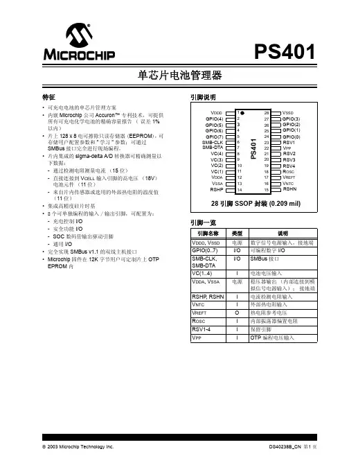
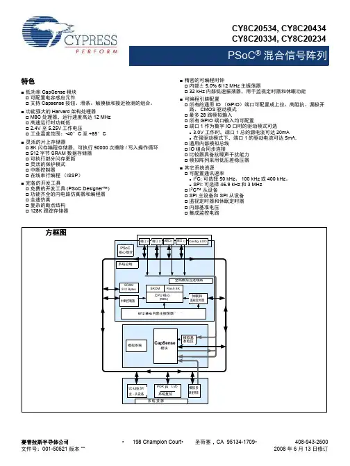
PSoC 4 电压比较器 (Comp) 1.0
- 格式:pdf
- 大小:393.65 KB
- 文档页数:11
![MCP4728-I2C-EEPROM_12 位四通道CN[1]--$1.37](https://uimg.taocdn.com/4c052bdd5022aaea998f0fb3.webp)
STC micro TM宏晶科技STC8G 系列单片机技术参考手册资料更新日期:2019/10/22目录1概述 (1)2特性及价格 (2)2.1 STC8G1K08系列特性及价格 (2)3管脚及说明 (4)3.1 管脚图 (4)3.1.1 STC8G1K08系列管脚图 (4)3.2 管脚说明 (6)3.2.1 STC8G1K08系列管脚说明 (6)3.3 功能脚切换 (9)3.3.1 功能脚切换相关寄存器 (9)3.4 范例程序 (10)3.4.1 串口1切换 (10)3.4.2 串口2切换 (11)3.4.3 SPI切换 (12)3.4.4 PCA/CCP/PWM切换 (13)3.4.5 I2C切换 (15)3.4.6 比较器输出切换 (16)3.4.7 主时钟输出切换 (17)4封装尺寸图 (19)4.1 TSSOP20封装尺寸图 (19)4.2 QFN20封装尺寸图(3mm*3mm) (20)4.3 SOP16封装尺寸图 (21)4.4 SOP8封装尺寸图 (22)4.5 STC8系列单片机命名规则 (23)5ISP下载及典型应用线路图 (24)5.1 STC8G系列ISP下载应用线路图 (24)5.1.1 使用RS-232转换器下载 (24)5.1.2 使用PL2303-SA下载 (25)5.1.3 使用PL2303-GL下载 (26)5.1.4 使用U8-Mini工具下载 (27)5.1.5 使用U8W工具下载 (28)5.1.6 USB直接ISP下载 (29)6时钟、复位与电源管理 (30)6.1 系统时钟控制 (30)6.2 STC8G系列内部IRC频率调整 (33)6.3 系统复位 (35)6.4 系统电源管理 (37)6.5 范例程序 (38)6.5.1 选择系统时钟源 (38)6.5.2 主时钟分频输出 (40)6.5.3 看门狗定时器应用 (41)6.5.4 软复位实现自定义下载 (42)6.5.5 低压检测 (44)6.5.6 省电模式 (45)6.5.7 使用INT0/INT1/INT2/INT3/INT4中断唤醒MCU (47)6.5.8 使用T0/T1/T2/T3/T4中断唤醒MCU (50)6.5.9 使用RxD/RxD2中断唤醒MCU (54)6.5.10 使用LVD中断唤醒MCU (56)6.5.11 使用CCP0/CCP1/CCP2中断唤醒MCU (58)6.5.12 CMP中断唤醒MCU (60)6.5.13 使用LVD功能检测工作电压(电池电压) (62)7存储器 (67)7.1 程序存储器 (67)7.2 数据存储器 (68)7.2.1 内部RAM (68)7.2.2 内部扩展RAM (69)7.3 存储器中的特殊参数 (70)7.3.1 读取Bandgap电压值(从ROM中读取) (71)7.3.2 读取Bandgap电压值(从RAM中读取) (74)7.3.3 读取全球唯一ID号(从ROM中读取) (76)7.3.4 读取全球唯一ID号(从RAM中读取) (79)7.3.5 读取32K掉电唤醒定时器的频率(从ROM中读取) (82)7.3.6 读取32K掉电唤醒定时器的频率(从RAM中读取) (84)7.3.7 用户自定义内部IRC频率(从ROM中读取) (87)7.3.8 用户自定义内部IRC频率(从RAM中读取) (89)8特殊功能寄存器 (91)8.1 STC8G1K08系列 (91)8.2 特殊功能寄存器列表 (92)9I/O口 (95)9.1 I/O口相关寄存器 (95)9.2 配置I/O口 (98)9.3 I/O的结构图 (99)9.3.1 准双向口(弱上拉) (99)9.3.2 推挽输出 (99)9.3.3 高阻输入 (99)9.3.4 开漏输出 (100)9.4 范例程序 (101)9.4.1 端口模式设置 (101)9.4.2 双向口读写操作 (102)9.4.3 用STC系列MCU的I/O口直接驱动段码LCD (103)10指令系统 (123)11中断系统 (127)11.1 STC8G系列中断源 (127)11.2 STC8中断结构图 (129)11.3 STC8系列中断列表 (130)11.4 中断相关寄存器 (132)11.4.1 中断使能寄存器(中断允许位) (132)11.4.2 中断请求寄存器(中断标志位) (135)11.4.3 中断优先级寄存器 (136)11.5 范例程序 (139)11.5.1 INT0中断(上升沿和下降沿) (139)11.5.2 INT0中断(下降沿) (140)11.5.3 INT1中断(上升沿和下降沿) (141)11.5.4 INT1中断(下降沿) (143)11.5.5 INT2中断(下降沿) (144)11.5.6 INT3中断(下降沿) (146)11.5.7 INT4中断(下降沿) (147)11.5.8 定时器0中断 (148)11.5.9 定时器1中断 (150)11.5.10 定时器2中断 (151)11.5.11 UART1中断 (153)11.5.12 UART2中断 (155)11.5.13 ADC中断 (157)11.5.14 LVD中断 (159)11.5.15 PCA中断 (160)11.5.16 SPI中断 (163)11.5.17 CMP中断 (164)11.5.18 I2C中断 (166)12定时器/计数器 (169)12.1 定时器的相关寄存器 (169)12.2 定时器0/1 (170)12.3 定时器2 (173)12.4 掉电唤醒定时器 (174)12.5 范例程序 (175)12.5.1 定时器0(模式0-16位自动重载) (175)12.5.2 定时器0(模式1-16位不自动重载) (176)12.5.3 定时器0(模式2-8位自动重载) (178)12.5.4 定时器0(模式3-16位自动重载不可屏蔽中断) (179)12.5.5 定时器0(外部计数-扩展T0为外部下降沿中断) (180)12.5.6 定时器0(测量脉宽-INT0高电平宽度) (182)12.5.7 定时器0(时钟分频输出) (183)12.5.8 定时器1(模式0-16位自动重载) (185)12.5.9 定时器1(模式1-16位不自动重载) (186)12.5.10 定时器1(模式2-8位自动重载) (187)12.5.11 定时器1(外部计数-扩展T1为外部下降沿中断) (189)12.5.12 定时器1(测量脉宽-INT1高电平宽度) (190)12.5.13 定时器1(时钟分频输出) (192)12.5.14 定时器1(模式0)做串口1波特率发生器 (193)12.5.15 定时器1(模式2)做串口1波特率发生器 (197)12.5.16 定时器2(16位自动重载) (200)12.5.17 定时器2(外部计数-扩展T2为外部下降沿中断) (202)12.5.18 定时器2(时钟分频输出) (203)12.5.19 定时器2做串口1波特率发生器 (205)12.5.20 定时器2做串口2波特率发生器 (208)13串口通信 (213)13.1 串口相关寄存器 (213)13.2 串口1 (214)13.2.1 串口1模式0 (215)13.2.2 串口1模式1 (216)13.2.3 串口1模式2 (219)13.2.4 串口1模式3 (219)13.2.5 自动地址识别 (220)13.3 串口2 (222)13.3.1 串口2模式0 (222)13.3.2 串口2模式1 (223)13.4 串口注意事项 (225)13.5 范例程序 (226)13.5.1 串口1使用定时器2做波特率发生器 (226)13.5.2 串口1使用定时器1(模式0)做波特率发生器 (229)13.5.3 串口1使用定时器1(模式2)做波特率发生器 (232)13.5.4 串口2使用定时器2做波特率发生器 (236)14比较器,掉电检测,内部固定比较电压 (240)14.1 比较器内部结构图 (240)14.2 比较器相关的寄存器 (241)14.3 范例程序 (243)14.3.1 比较器的使用(中断方式) (243)14.3.2 比较器的使用(查询方式) (245)14.3.3 比较器作外部掉电检测 (247)14.3.4 比较器检测工作电压(电池电压) (249)15IAP/EEPROM (253)15.1 EEPROM相关的寄存器 (253)15.2 EEPROM大小及地址 (255)15.3 范例程序 (257)15.3.1 EEPROM基本操作 (257)15.3.2 使用MOVC读取EEPROM (260)15.3.3 使用串口送出EEPROM数据 (263)16ADC模数转换 (268)16.1 ADC相关的寄存器 (268)16.2 范例程序 (271)16.2.1 ADC基本操作(查询方式) (271)16.2.2 ADC基本操作(中断方式) (272)16.2.3 格式化ADC转换结果 (274)16.2.4 利用ADC第16通道测量外部电压或电池电压 (276)17PCA/CCP/PWM应用 (279)17.1 PCA相关的寄存器 (279)17.2 PCA工作模式 (282)17.2.1 捕获模式 (282)17.2.2 软件定时器模式 (282)17.2.3 高速脉冲输出模式 (283)17.2.4 PWM脉宽调制模式 (283)17.3 范例程序 (287)17.3.1 PCA输出PWM(6/7/8/10位) (287)17.3.2 PCA捕获测量脉冲宽度 (289)17.3.3 PCA实现16位软件定时 (292)17.3.4 PCA输出高速脉冲 (295)17.3.5 PCA扩展外部中断 (298)18同步串行外设接口SPI (301)18.1 SPI相关的寄存器 (301)18.2 SPI通信方式 (303)18.2.1 单主单从 (303)18.2.2 互为主从 (303)18.2.3 单主多从 (304)18.3 配置SPI (305)18.4 数据模式 (307)18.5 范例程序 (308)18.5.1 SPI单主单从系统主机程序(中断方式) (308)18.5.2 SPI单主单从系统从机程序(中断方式) (310)18.5.3 SPI单主单从系统主机程序(查询方式) (311)18.5.4 SPI单主单从系统从机程序(查询方式) (313)18.5.5 SPI互为主从系统程序(中断方式) (315)18.5.6 SPI互为主从系统程序(查询方式) (317)19I2C总线 (320)19.1 I2C相关的寄存器 (320)19.2 I2C主机模式 (321)19.3 I2C从机模式 (324)19.4 范例程序 (327)19.4.1 I2C主机模式访问AT24C256(中断方式) (327)19.4.2 I2C主机模式访问AT24C256(查询方式) (332)19.4.3 I2C主机模式访问PCF8563 (338)19.4.4 I2C从机模式(中断方式) (343)19.4.5 I2C从机模式(查询方式) (347)19.4.6 测试I2C从机模式代码的主机代码 (351)20增强型双数据指针 (357)20.1 范例程序 (359)20.1.1 示例代码1 (359)20.1.2 示例代码2 (359)附录A无 (361)附录B无 (366)附录C使用第三方MCU对STC8G系列单片机进行ISP下载范例程序 (429)附录D电气特性 (437)附录E应用注意事项 (439)附录F STC8G系列头文件 (440)附录G更新记录 (444)1概述STC8G系列单片机是不需要外部晶振和外部复位的单片机,是以超强抗干扰/超低价/高速/低功耗为目标的8051单片机,在相同的工作频率下,STC8G系列单片机比传统的8051约快12倍(速度快11.2~13.2倍),依次按顺序执行完全部的111条指令,STC8G系列单片机仅需147个时钟,而传统8051则需要1944个时钟。
![4位数值比较器设计[整理]](https://uimg.taocdn.com/2d225801effdc8d376eeaeaad1f34693daef106a.webp)
4位数值比较器设计[整理]四位数值比较器是一种常见的数字电子电路,广泛应用于计算机、通信、控制等领域。
其主要功能是将两个四位数字进行比较,输出比较结果。
下面将介绍如何设计一款四位数值比较器。
一、功能描述四位数值比较器输入两个四位数字A、B,比较它们的大小关系,输出比较结果。
如果A>B,输出1;如果A<B,输出-1;如果A=B,输出0。
二、设计步骤1.分析功能需求根据功能描述,我们需要完成以下任务:(1)输入两个四位数字A、B。
(2)将两个数字进行比较。
(3)输出比较结果。
2.确定输入输出端口和数据宽度根据上述功能需求,我们可以确定输入为两个4位数字A、B,输出为1位数字(1、0或-1)。
因此,输入端口需要8个引脚(4位输入A、4位输入B),输出端口需要1个引脚。
3.分析比较规则比较规则可以分为以下几个步骤:(1)判断A和B的位数是否相等,如果不相等,则将位数不足的数字前面补0。
(2)从高位开始比较A和B的每一位数字,如果相同,则继续比较下一位,如果不同,则输出A和B相应位数之差的符号。
(3)全部比较完成后,如果A=B,则输出0。
4.设计电路原理图基于上述分析,我们可以得到四位数值比较器的电路原理图,如下所示:(A>B)——Y=15.实现电路功能实现上述电路原理图的功能,需要对每个子模块进行详细设计和调试。
具体实现过程如下:(1)比较器比较器的功能是比较两个数的大小关系。
本电路中采用了四位全加器(4-bit full adder)实现比较器的功能。
根据比较规则,当A和B的相应位数相同时,将A和B相应位数之差的符号作为比较结果进行输出。
具体电路原理如下图所示:(2)选择器选择器的功能是根据比较结果输出相应的数值。
由于比较结果输出的是1、0或-1,因此我们需设置三个选择器,用于分别输出明确的比较结果。
具体电路原理如下图所示:多路选择器的作用是判断A和B的数字位数是否相同,并在数字位数不同时将位数不足的数字前面补0。
CYIV-51006-2.3© 2011 Altera Corporation. All rights reserved. ALTERA, ARRIA, CYCLONE, HARDCOPY, MAX, MEGACORE, NIOS, QUARTUS and STRATIX words and logos aretrademarks of Altera Corporation and registered in the U.S. Patent and Trademark Office and in other countries. All other words and logos identified as trademarks or service marks are the property of their respective holders as described at /common/legal.html . Altera warrants performance of its semiconductor products to current specifications in accordance with Altera's standard warranty, but reserves the right to make changes to any products and services at any time without notice. Altera assumes no responsibility orliability arising out of the application or use of any information, product, or service described herein except as expressly agreed to in writing by Altera. Altera customers are advised to obtain the latest version of device specifications before relying on any published information and before placing orders for products or services.Cyclone IV 器件手册,卷12011年11月ISO 9001:2008 RegisteredSubscribe6.Cyclone IV 器件中的I/O 特性本章节介绍了Cyclone ® IV 器件所支持的I/O 与高速I/O 的性能和特性。
Description The LM2901/2903 series comparators consist of four and two independent precision voltage comparators with very low input offset voltage specification. They are designed to operate from a single power supply over a wide range of voltages; however operation from split power supplies is also possible. They offer low power supply current independent of the magnitude of the power supply voltage.The LM2901/2903 series comparators are designed to directly interface with TTL and CMOS. When operating from both plus and minus power supplies, the LM2901/2903 series comparators will directly interface with MOS logic where their low power drain is a distinct advantage over standard comparators.The dual devices are available in SO-8, TSSOP-8, and MSOP-8, and the quad devices available in SO-14 and TSSOP-14 with industry standard pinouts. Both use green mold compound as standard.Features•Wide Power Supply Range: ▪ Single Supply: 2V to 36V ▪ Dual Supplies: ±1.0V to ±18V•Very Low Supply Current Drain—Independent of Supply Voltage ▪ LM2903: 0.6mA ▪ LM2901: 0.9mA• Low Input Bias Current: 25nA • Low Input Offset Current: ±5nA •Typical Offset Voltage: ▪ Non-A Device: 2mV ▪ A Device: 1mV• Common-Mode Input Voltage Range Includes Ground• Differential Input Voltage Range Equal to the Power Supply Voltage•Low Output Saturation Voltage: ▪ LM2903: 200mV at 4mA ▪ LM2901: 100mV at 4mA• Output Voltage Compatible with TTL, MOS and CMOS• Totally Lead-Free & Fully RoHS Compliant (Notes 1 & 2) •Halogen and Antimony Free. “Green” Device (Note 3)Pin Assignments(Top View)SO-8/TSSOP-8/MSOP-81OUT V CC2IN-2IN+1IN-1IN+GND2OUTLM2903/ LM2903A(Top View)SO-14/TSSOP-141OUT 3OUT GND4IN+3IN-3IN+4IN-2OUTV CC2IN-2IN+1IN-1IN+4OUTLM2901/ LM2901ANotes: 1. No purposely added lead. Fully EU Directive 2002/95/EC (RoHS), 2011/65/EU (RoHS 2) & 2015/863/EU (RoHS 3) compliant.2. See https:///quality/lead-free/ for more information about Diodes Incorporated’s definitions of Halogen- and Antimony-free, "Green" and Lead-free.3. Halogen- and Antimony-free "Green” products are defined as those which contain <900ppm bromine, <900ppm chlorine (<1500ppm total Br + Cl) and <1000ppm antimony compounds.Schematic DiagramOUTPUT-INPUTFunctional Block Diagram of LM2901/2901A/2903/2903A(Each Comparator)Pin DescriptionsLM2901, LM2901APin Name Pin # Function1OUT 1 Channel 1 Output2OUT 2 Channel 2 OutputV CC 3 Chip Supply Voltage2IN- 4 Channel 2 Inverting Input2IN+ 5 Channel 2 Non-Inverting Input1IN- 6 Channel 1 Inverting Input1IN+ 7 Channel 1 Non-Inverting Input3IN- 8 Channel 3 Inverting Input3IN+ 9 Channel 3 Non-Inverting Input4IN- 10 Channel 4 Inverting Input4IN+ 11 Channel 4 Non-Inverting InputGND 12 Ground4OUT 13 Channel 4 Output3OUT 14 Channel 3 OutputLM2903, LM2903A1OUT 1 Channel 1 Output1IN- 2 Channel 1 Inverting Input1IN+ 3 Channel 1 Non-Inverting InputGND 4 Ground2IN+ 5 Channel 2 Non-Inverting Input2IN- 6 Channel 2 Inverting Input2OUT 7 Channel 2 OutputV CC8 Chip Supply VoltageNotes: 4. Stresses beyond those listed under Absolute Maximum Ratings can cause permanent damage to the device. These are stress ratings only; functional operation of the device at these or any other conditions beyond those indicated under recommended operating conditions is not implied. Exposure to absolute-maximum-rated conditions for extended periods can affect device reliability.5. Short circuits from outputs to V CC can cause excessive heating and eventual destruction.6. Maximum power dissipation is a function of T J(MAX), θJA, and T A. The maximum allowable power dissipation at any allowable ambient temperature isP D = (T J(MAX)− T A)/θJA. Operating at the absolute maximum T J of 150°C can affect reliability.7. Human body model, 1.5kΩ in series with 100pF.Notes:8. Typical values represent the most likely parametric norm as determined at the time of characterization. Actual typical values may vary over time and will also depend on the application and configuration. The typical values are not tested and are not guaranteed on shipped production material.9. All limits are guaranteed by testing or statistical analysis. Limits over the full temperature are guaranteed by design, but not tested in production.10.V O ≅1.4V, R S= 0Ω with V CC from 5V to 30V;11.The direction of the input current is out of the IC due to the PNP input stage. This current is essentially constant, independent of the state of the output sono loading change exists on the input lines.12.The input common-mode voltage of either input signal voltage should not be allowed to go negative by more than 0.3V (@ +25°C). The upper end of thecommon-mode voltage range is V CC -1.5V (@ +25°C), but either or both inputs can go to +36V without damage, independent of the magnitude of V CC.13. The response time specified is for a 100mV step input with 5mV overdrive. For larger overdrive signals 300ns can be obtained, see typical performancecharacteristics.14. Positive excursions of input voltage may exceed the power supply level. As long as other voltages remain within the common mode range, thecomparator will provide a proper output stage. The low voltage state must not be less than -0.3V (or 0.3V below the magnitude of the negative powersupply, if used).Notes:8. Typical values represent the most likely parametric norm as determined at the time of characterization. Actual typical values may vary over time and will also depend on the application and configuration. The typical values are not tested and are not guaranteed on shipped production material.9. All limits are guaranteed by testing or statistical analysis. Limits over the full temperature are guaranteed by design, but not tested in production.10.V O ≅1.4V, R S= 0Ω with V CC from 5V to 30V;11.The direction of the input current is out of the IC due to the PNP input stage. This current is essentially constant, independent of the state of the output sono loading change exists on the input lines.12.The input common-mode voltage of either input signal voltage should not be allowed to go negative by more than 0.3V (@ +25°C). The upper end of thecommon-mode voltage range is V CC -1.5V (@ +25°C), but either or both inputs can go to +36V without damage, independent of the magnitude of V CC.13. The response time specified is for a 100mV step input with 5mV overdrive. For larger overdrive signals 300ns can be obtained, see typical performancecharacteristics.14. Positive excursions of input voltage may exceed the power supply level. As long as other voltages remain within the common mode range, thecomparator will provide a proper output stage. The low voltage state must not be less than -0.3V (or 0.3V below the magnitude of the negative powersupply, if used).Performance CharacteristicsSupply Current vs. Supply Voltage Supply Current vs. Supply VoltageSupply Current vs. Temperature Supply Current vs. TemperatureOutput Saturation Voltage vs. Sink Current Output Saturation Voltage vs. Sink CurrentPerformance Characteristics (continued)Response Time for Various Input Overdrive Response Time for Various Input OverdriveInput Current vs. Supply Voltage Input Current vs. TemperatureApplication InformationGeneral InformationThe LM2901/2903 series comparators are high-gain, wide bandwidth devices. Like most comparators, the series can easily oscillate if the output lead is inadvertently allowed to capacitive couple to the inputs via stray capacitance. This shows up only during the output voltage transition intervals as the comparators change states. Standard PC board layout is helpful as it reduces stray input-output coupling. Reducing the input resistors to <10kΩreduces the feedback signal levels. Finally, adding even a small amount (1.0mV to 10mV) of positive feedback (hysteresis) causes such a rapid transition that oscillations, due to stray feedback, are not possible. Simply socketing the IC and attaching resistors to the pins will cause input-output oscillations during the small transition intervals unless hysteresis is used. If the input signal is a pulse waveform, with relatively fast rise and fall times, hysteresis is not required. All input pins of any unused comparators should be tied to the negative supply.The bias network of the LM2901/2903 series comparators establishes a quiescent current independent of the magnitude of the power supply voltage over the range of from 2.0V DC to 30V DC.The differential input voltage may be larger than V CC without damaging the device. Protection should be provided to prevent the input voltages from going negative more than -0.3V DC (@ +25°C). An input clamp diode can be used as shown in the applications section.The output of the LM2901/2903 series comparators is the uncommitted collector of a grounded-emitter NPN output transistor. Many collectors can be tied together to provide an output ORing function. An output pull-up resistor can be connected to any available power supply voltage within the permitted supply voltage range and there is no restriction on this voltage due to the magnitude of the voltage applied to the V CC terminal of LM2901/2903 series comparator package. The output can also be used as a simple SPST switch to ground (when a pull-up resistor is not used).The amount of current the output device can sink is limited by the drive available (which is independent of V CC) and the β of this device. When the maximum current limit is reached (approximately 16mA), the output transistor will come out of saturation and the output voltage will rise very rapidly. The output saturation voltage is limited by the approximately 60ΩR SAT of the output transistor. The low offset voltage of the output transistor (1.0mV) allows the output to clamp essentially to ground level for small load currents.Typical Application Circuit (V CC = 5.0V DC )Typical Application Circuit(V CC = 5.0V DC) (continued)Typical Application Circuit (V CC = 5.0V DC ) (continued)Ordering Information (Note 15)LM290X X XXX - 13ChannelGrade3 : Dual PackingPackageS : SO-813 : Tape & Reel1 : Quad A : Low V IOBlank : Normal S14 : SO-14T14 : TSSOP-14M8: MSOP-8TH: TSSOP-8Part Number Package CodePackaging 13” Tape and ReelQuantity Part Number SuffixLM2901T14-13 T14 TSSOP-14 2500/Tape & Reel -13 LM2901AT14-13 T14 TSSOP-14 2500/Tape & Reel -13 LM2901S14-13 S14 SO-14 2500/Tape & Reel -13 LM2901AS14-13 S14 SO-14 2500/Tape & Reel -13 LM2903S-13 S SO-8 2500/Tape & Reel -13 LM2903AS-13 S SO-8 2500/Tape & Reel -13 LM2903AM8-13 M8 MSOP-8 2500/Tape & Reel -13 LM2903M8-13 M8 MSOP-8 2500/Tape & Reel -13 LM2903ATH-13 TH TSSOP-8 2500/Tape & Reel -13 LM2903TH-13THTSSOP-82500/Tape & Reel-13Note: 15. For packaging details, go to our website at /products/packages.html.Marking Information (1) TSSOP-14 and SO-14(2) SO-8(3) MSOP-8 & TSSOP-8Package Outline DimensionsPlease see /package-outlines.html for the latest version.SO-8SO-8Dim Min Max A − 1.75 A1 0.10 0.20 A2 1.30 1.50 A3 0.15 0.25 b 0.3 0.5 D 4.85 4.95 E 5.90 6.10 E1 3.85 3.95 e 1.27 Typ h − 0.35 L 0.62 0.82θ0° 8° All Dimensions in mmTSSOP-8MSOP-8MSOP-8Dim Min Max Typ A − 1.10 − A1 0.05 0.15 0.10 A2 0.75 0.95 0.86 A3 0.29 0.49 0.39 b 0.22 0.38 0.30 c 0.08 0.23 0.15 D 2.90 3.10 3.00 E 4.70 5.10 4.90 E1 2.90 3.10 3.00 E3 2.85 3.05 2.95 e − −0.65 L 0.400.80 0.60 a 0° 8° 4° x − − 0.750 y − − 0.750 All Dimensions in mmGauge Plane Seating PlaneDetail ‘A’Detail CSee Detail CDetail CPackage Outline Dimensions (continued)Please see /package-outlines.html for the latest version.SO-14SO-14Dim Min Max A 1.47 1.73 A1 0.10 0.25 A2 1.45 Typ B 0.33 0.51 D 8.53 8.74 E 3.80 3.99 e 1.27 Typ H 5.80 6.20 L 0.38 1.27θ0° 8° All Dimensions in mmTSSOP-14TSSOP-14 Dim Min Max a1 7° (4X) a2 0° 8° A 4.9 5.10 B 4.30 4.50 C − 1.2 D 0.8 1.05 F 1.00 Typ F1 0.45 0.75 G 0.65 Typ K 0.19 0.30 L 6.40 Typ All Dimensions in mmDetail “A”Pin# 1 Detail ‘A’Gauge Plane Seating PlaneSuggested Pad LayoutPlease see /package-outlines.html for the latest version.SO-8TSSOP-8MSOP-8XC2YSuggested Pad Layout (continued)Please see /package-outlines.html for the latest version.SO-14TSSOP-14XC1XC1。
四电压比较器电路LM3391.概述与特点LM339是一块由四个独立的精密电压比较器组成的电路,该电路具有低失调电压的特点,各比较器的失调电压不大于5Mv,可广泛应用于工业自动化和光机、电、一体化等领域。
其特点如下●工作电源电压范围宽;单电源2V~36V,双电源1V~18V●静态电流小:0.8mA(典型值)●低输入偏置电流:25nA(典型值)●低输入失调电压:2mV(典型值)●共模输入电压范围宽:0V~Vcc-1.5V●集电极开路输出,方便与TTL、CMOS逻辑相容●封装形式:DIP142. 功能框图与引脚说明2. 1功能框图2. 2 引脚说明引脚符号功能引脚符号功能1 OUT2输出2 8 IN3-反相输入32 OUT1输出1 9 IN3+同相输入33 V CC电源10 IN4-反相输入44 IN1-反相输入1 11 IN4+ 同相办入45 IN1+同相输入1 12 GND 地6 IN1-反相输入2 13 OUT4输出47 IN1+同相输入2 14 OUT3输出33.电特性3. 1极限参数除非另有规定Tamb= 25℃参数名称 符号 额定值 单位电源电压 V CC36/±18 V输入差模电压 V IDR±36 V输入共模电压 V ICR-0.3~VCC V功耗 P D625 mA 工作环境温度 T amb-40~85 ℃贮存温度 T stg-55~125 ℃ 3. 2 电特性除非另有规定Tamb = 25℃,VCC= 5V规范值参数名称符号测试条件最小典型最大单位图号静态电流I CCQ无负载0.8 2 mA 4.1 输入失调电压V IO V O=1.4V ±2 ±5mA 4.4 输入偏置电流I IB25 250 nA 4.2 输入失调电流I IO 5 50 nA 4.2 输入共模电压范围V ICR0 V CC-1.5 V 4.4 开环电压增益A V R L=15KOHM 200 V/mV响应时间T r R L=5.1KOHM 1.3 uS 4.6输出灌电流I SINK IN+=0V, IN-=1VV OL=1.5V6 16 mA 4.5输出饱和电压V OL IN+=0V, IN-=1VI SINK =3mV0.2 0.4 V 4.5输出漏电流I OS IN+=0V, IN-=1VVo =5V0.1 nA 4.34. 测试线路4.1静态电流测试线路 4.2输入偏置电流与失调电流测试线路4.3输出漏电流测试线路 4.4输入失调电压与输入共模电压测试线路4.5输出灌电流和饱和电压测试线路 4.6 响应时间测试线路5典线特性6. 线路与应用说明 6. 1 应用线路6. 1. 1驱动TTL电路6. 1. 2驱动CMOS电路6. 2 应用说明7.外型尺寸。
闲话Zynq UltraScale+ MPSoC(连载3)图 4 电源系统比较Part1:电源系统相比于Zynq-7000,这个电源系统要复杂一些,咱抛开低功耗版本(-L)的不谈,就谈正常情况,PS端也把电源域分成了普通电源域和低功耗电源域,然后PS端的GTR也是单独供电的,还有还有,这个GTR的电压竟然和PL端的GTH 完全不同。
图4是Zynq-7000和Zynq UltraScale MPSoC电源系统的比较。
典型的是,内核电压由1.0V降至0.85V,PS端多了专门的GTR电压。
更低的核电压,更多的核消耗和更高的时钟频率意味着更大的电流,预估PL和PS的内核光静态电流就在3A左右。
同时新的Zynq UltraScale+ MPSoC PS端有两个电源域,分别是全功耗电源域和低功耗电源域。
二者的PL和PS间都是独立的。
关于上电顺序,Zynq-7000的要求是:a) PS : 先同时上VCCPINT、VCCPAUX和VCCPLL,再上VCCO(MIO、DDR),但VCCO上电延时相对于VCCPAUX有一个必须遵守的最大延迟时间。
b) PL : 先后依次是VCCINT、 VCCBRAM、 VCCAUX和 VCCO,VCCO上电延时相对于VCCAUX有一个必须遵守的最大延迟时间。
但是Zynq UltraScale+ MPSoC有不同的要求:a) 在PS系统里,必须保证低功耗电源域先上电,待上电完成后再给全功耗系统上电。
b) 在低功耗电源域内的上电顺序是:VCCPINTLP先上电,然后VCCPAUX、VCCPADC、和VCCPLL没有特别要求,最后给VCCOPIO上电。
c) 在全功耗电源域内先给VCCPINTFP(VCCPINTFP_DDR)上电,然后VMGTRAVCC、 VCCPLL和 VCCDDRPLL以任何顺序上电,最后是给MGTRAVTT和VCCODDR上电。
d) PL 上电完全独立,依次是VCCINT、VCCINT_IO/VCCBRAM、VCCAUX/VCCAUX_IO和 VCCO。
四位数值比较器班级:电子信息工程(2)班姓名:林贤款学号:Xb13610208时间:2015.12—2015.12 一、实验目的。
1、设计四位二进制码比较器,并在QuantusII上进行仿真。
2、掌握VHDL设计实体的基本结构及文字规则。
二、实验要求。
1、用VHDL语言编写四位二进制码比较器的源文件;2、对设计进行仿真验证;三、实验原理。
本实验实现要实现两个4位二进制码的比较器。
即当输入为两个4位二进制码和时, 输出为M(A=B),G(A>B)和L(A<B)(如右图所示)。
用高低电平开关作为输入,发光二极管作为输出。
当A=B时,M处接的二极管亮;当A>B时,G处接的二极管亮;当A<B时,L 处接的二极管亮。
具体管脚安排根据试验系统的实际情况自行定义。
四、实验器材。
1、EDA开发软件一台;2、装有QuantusII软件电脑一台。
五、实验步骤。
1、打开软件。
快捷工具栏:提供设置(setting),编译(compile)等快捷方式,方便用户使用,用户也可以在菜单栏的下拉菜单找到相应的选项。
菜单栏:软件所有功能的控制选项都可以在其下拉菜单中找到。
信息栏:编译或者综合整个过程的详细信息显示窗口,包括编译通过信息和报错信息。
2、新建工程。
(1)选择File菜单下New Project Wizard。
(2)输入工作目录和项目名称。
(3)加入已有的设计文件到项目,可以直接选择Next,设计文件可以在设计过程中加入。
(4)选择设计器件。
(5)选择第三方EDA综合、仿真和时序分析工具。
(6)建立项目完成,显示项目概要。
3、添加文件(file>new> VHDL file),新建完成之后要先保存。
4、编写程序(原程序如下a所述)。
5、检查语法(点击工具栏的这个按钮)。
6、锁定引脚,点击工具栏的(如下管脚分配所述)。
六、实验结果。
1、编译结果无误图。
2、仿真波形图:当=1011,=1101时,A<B,L为高电平,即L=1。