ABB DCS系统培训手册
- 格式:pdf
- 大小:7.66 MB
- 文档页数:54
S4C IRB 基本操作培训教材目录1、培训教材介绍2、机器人系统安全及环境保护3、机器人综述4、机器人启动5、用窗口进行工作6、手动操作机器人7、机器人自动生产8、编程与测试9、输入与输出10、系统备份与冷启动11、机器人保养检查表附录1、机器人安全控制链附录2、定义工具中心点附录3、文件管理1、培训教材介绍本教材解释ABB机器人的基本操作、运行。
你为了理解其内容不需要任何先前的机器人经验。
本教材被分为十一章,各章分别描述一个特别的工作任务和实现的方法。
各章互相间有一定联系。
因此应该按他们在书中的顺序阅读。
借助此教材学习操作操作机器人是我们的目的,但是仅仅阅读此教材也应该能帮助你理解机器人的基本的操作。
此教材依照标准的安装而写,具体根据系统的配置会有差异。
机器人的控制柜有两种型号。
一种小,一种大。
本教材选用小型号的控制柜表示。
大的控制柜的柜橱有和大的一个同样的操作面板,但是位于另一个位置。
请注意这教材仅仅描述实现通常的工作作业的某一种方法,如果你是经验丰富的用户,可以有其他的方法。
其他的方法和更详细的信息看下列手册。
《使用指南》提供全部自动操纵功能的描述并详细描述程序设计语言。
此手册是操作员和程序编制员的参照手册。
《产品手册》提供安装、机器人故障定位等方面的信息。
如果你仅希望能运行程序,手动操作机器人、由软盘调入程序等,不必要读8-11章。
2、机器人系统安全及环境保护机器人系统复杂而且危险性大,在训练期间里,或者任何别的操作过程都必须注意安全。
无论任何时间进入机器人周围的保护的空间都可能导致严重的伤害。
只有经过培训认证的人员才可以进入该区域。
请严格注意。
以下的安全守则必须遵守。
•万一发生火灾,请使用二氧化碳灭火器。
•急停开关(E-Stop)不允许被短接。
•机器人处于自动模式时,不允许进入其运动所及的区域。
•在任何情况下,不要使用原始盘,用复制盘。
•搬运时,机器停止,机器人不应置物,应空机。
•意外或不正常情况下,均可使用E-Stop键,停止运行。
ABB DCS系统MODBUS通讯简介一、概述:DCS MODBUS的通讯组态,了解整个的组态过程和信号的传送方式,在调试中,按MODBUS规程的约定,一般读数字量使用02功能代码,读模拟量使用03功能代码,写开关量使用05或者15功能代码, 写模拟量使用06或16功能代码.在MODBUS的编程时注意: 选择功能代码02时在GPI软件中对应数据类型为DIP,选择功能代码03时时在GPI软件中对应数据类型为AOP;选择功能代码01或者05时在GPI软件中对应数据类型为DOP;选择功能代码06时在GPI软件中对应数据类型为DOP;另外还需电气通讯管理机确定数字量和模拟量的起始地址,以方便编程。
可双方书面约定),每个设备一个PLC地址。
通讯管理机全是一个设备地址,数字量与模拟量的RTU地址可重复,数字量需要一次读16个数据,在组态时要注意,模拟量没有要求;电气来的信号要考虑信号的系数问题,在MODBUS编程时要注意;另外电气还有长整型数据(比如电度量),在DCS的接口部分无法处理,只能在信号进入DCS后由组态进行处理,这还需要到现场后进行测试.二.硬件连接和地址设置:硬件连接图MFP12 模件方框图(functional block diagram):其中: ROM 512 kilobyte; RAM 512 kilobyte; NVRAM 256 kilobyte用户可用:347,712 byteS RAM, 194,752 bytes NVRAMDMA: directly memory access ,allows data received or transmitted.1.从PLC或者其他设备来的通讯接口首先连接至ADAM4520的DATA端,注意要直连,也即对方的正端接至ADAM4520的DATA+端,也即对方的负端接至ADAM4520的DATA-端, 然后通过一根通讯线将ADAM4520上的9针串口转换为NTMP端子上的25针串口,注意接法为: NTMP 端子上的25针串口pin 2、3、7分别对应ADAM4520 模块的9针串口的pin2、3、5;2.MFP12 模块拨码开关的设置:a.SW3: 模件地址和运行方式选择;具体如下:举例如下:MFP12采用正常的工作模式,并且地址为6,则SW3的设置为:6和7设为OPEN,其余全为CLOSED.b.SW4: 模件的特殊操作选择.具体如下当使用单网进行通讯时,SW4一般都设为CLOSED;当用于冗余通讯时,需要对POLE 8进行设置: 主MFP12 设为0,冗余MFP12设为1.值得注意的是,在做MODBUS通讯之前,先要对模件进行特殊操作,方法为:(1)1、7操作(即2操作):先将SW4的POLE 1和7拨为1,将MFP12模件推进去,然后再拔出来,再将POLE 1和7拨为0,再次将模件推进去,通过这样的操作,结果将NVRAM存储器进行了初始化;(2)1、6操作(即4操作):先将SW4的POLE 1和6拨为1,将MFP12模件推进相应槽位,然后再拔出来,再将POLE 1和6拨为0,再次将模件推进去,通过这样的操作,使得 Cnet或者INFI-NET网络规程成立.3.串口通讯接线方式:RS2321969年,美国电子工业协会(EIA)公布了RS-232C作为串行通信接口的电气标准,该标准定义了数据终端设备(DTE)和数据通信设备(DCE)间按位串行传输的接口信息,合理安排了接口的电气信号和机械要求,在世界范围内得到广泛的应用。

HC900 DCS操作员手册目录一.系统概述二.操作员软件(Station)介绍三.流程图操作四.细目画面操作五.报警汇总操作六.事件操作七.趋势组操作八.操作组操作九.附录(流程图)一、系统概述本装置DCS采用的是美国HONEYWELL公司的HC900系统,HC900作为一个混合控制器,既具有DCS连续控制的优点,又具有PLC(可编程控制器)逻辑控制的优点,主要用于中小型的连续控制和逻辑控制领域,其上位机组态软件采用的是HONEYWELL 的PLANTSCAPE R400系统。
HC900 DCS的结构如下图一:(图一:HC900 DCS结构)MTBE装置采用了3个HC900控制,其中1#和2#控制器是一对冗余的控制器,采用外部继电器进行切换,主要用于带控制的仪表回路;3#控制器是不带冗余的控制器,用于不带控制的仪表回路的调节和显示。
由于冗余控制器的切换采用的是外部继电器的切换,因此,每一个带控制的仪表回路都采用了两个仪表位号(A和B),这样就要求工艺操作员不能直接在细目画面或操作组画面修改参数,必须在流程图画面下修改参数。
而且由于软件本身的缺陷,权限设置有问题,这就要求操作员不能随意的修改细目画面的其它参数。
配备了两台操作站,同时兼做工程师站,采用奔4 CPU,21寸的纯平显示器,操作系统为WINDOWS 2000英文专业版。
同时配置了一台激光打印机,用于流程图和历史趋势的打印。
HC900控制器与操作站之间采用以太网方式进行连接,即通过三个HUB和五类双绞线组成一个星型网络结构,采用的是MODBUS/TCP协议进行数据通讯。
其组态软件包括控制器组态软件Hybrid Control Designer;数据库组态软件Quick Builder;流程图组态软件Display Builder;操作站软件Station。
工艺操作人员主要在Station软件中对现场仪表设备进行监控。
二、操作员软件(Station)介绍1、Station软件界面整体结构见图二:(图二:Station软件界面整体结构)2、菜单介绍:View Menu:Control Menu:Action Menu:3、工具条介绍:4、状态条介绍5、命令区介绍直接在命令区(Command Zone)输入命令后回车。
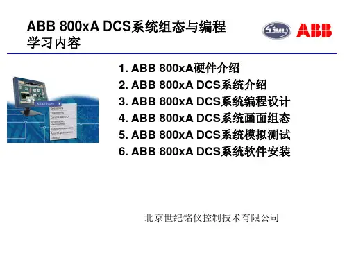
2011 年 12月生产分厂仪表专业组培训讲义一、讲师(部门:生产分厂专业组:仪表职:DCS技术员姓名:尹海生工号:30721)二、主题:ABB 800XA DCS系统基础讲义三、时间:地点:四、培训部门专业岗位及人数:五、培训目的(培训结束后,受训人员应掌握的专业知识或技能,对工作的帮助如何):通过此次培训:认识ABB集散控制系统硬件组成和作用。
操作站员站、操作站终端、控制器之间的网络连接结构。
日常点检内容,常见问题及其处理方法。
六、讲义提纲:1、集散控制概述2、硬件系统及简单的控制原理3、控制网络结构4、日常点检内容与维护5、常见问题及处理方法目录1.集散控制概述 (3)1.1DCS定义 (3)1.2DCS与PLC的异同 (3)2.系统概述 (4)3.硬件系统及简单控制原理 (5)3.1AC800M硬件的组成 (5)3.1.1控制器简介 (5)3.1.2电源 (6)3.1.3AC800M控制器接口 (6)3.2PID控制原理 (7)3.2.1PID的含义及控制规律的选用 (7)3.2.2PID控制方式 (7)3.2.3PID参数的基本计算(略) (7)3.3DCS简单控制逻辑 (8)3.4其他硬件 (8)3.5硬件安装更换指导 (8)4.控制网络结构 (9)4.1网络结构 (9)4.2AS和CS示例 (9)5.日常点检内容及维护 (9)6.常见故障及处理方法 (10)6.1IO卡件故障 (10)6.2通讯卡故障 (10)6.3DCS画面“” (10)1. 集散控制概述1.1 DCS定义DCS是分布式控制系统的英文缩写(Distributed Control System),在国内自控行业又称之为集散控制系统。
它是一个由过程控制级和过程监控级组成的以通信网络为纽带的多级计算机系统,综合了计算机(Computer)、通讯(Communication)、显示(CRT)和控制(Control)等4C技术,其基本思想是分散控制、集中操作、分级管理、配置灵活、组态方便。

ABB800XADCS系统基础讲义2011 年 12⽉⽣产分⼚仪表专业组培训讲义⼀、讲师(部门:⽣产分⼚专业组:仪表职:DCS技术员姓名:尹海⽣⼯号:30721)⼆、主题:ABB 800XA DCS系统基础讲义三、时间:地点:四、培训部门专业岗位及⼈数:五、培训⽬的(培训结束后,受训⼈员应掌握的专业知识或技能,对⼯作的帮助如何):通过此次培训:认识ABB集散控制系统硬件组成和作⽤。
操作站员站、操作站终端、控制器之间的⽹络连接结构。
⽇常点检内容,常见问题及其处理⽅法。
六、讲义提纲:1、集散控制概述2、硬件系统及简单的控制原理3、控制⽹络结构4、⽇常点检内容与维护5、常见问题及处理⽅法⽬录1.集散控制概述 (3)1.1DCS定义 (3)1.2DCS与PLC的异同 (3)2.系统概述 (4)3.硬件系统及简单控制原理 (5)3.1AC800M硬件的组成 (5)3.1.1控制器简介 (5)3.1.2电源 (6)3.1.3AC800M控制器接⼝ (6)3.2PID控制原理 (7)3.2.1PID的含义及控制规律的选⽤ (7)3.2.2PID控制⽅式 (7)3.2.3PID参数的基本计算(略) (7)3.3DCS简单控制逻辑 (8)3.4其他硬件 (8)3.5硬件安装更换指导 (8)4.控制⽹络结构 (9)4.1⽹络结构 (9)4.2AS和CS⽰例 (9)5.⽇常点检内容及维护 (9)6.常见故障及处理⽅法 (10)6.1IO卡件故障 (10)6.2通讯卡故障 (10)6.3DCS画⾯“” (10)1. 集散控制概述1.1 DCS定义DCS是分布式控制系统的英⽂缩写(Distributed Control System),在国内⾃控⾏业⼜称之为集散控制系统。
它是⼀个由过程控制级和过程监控级组成的以通信⽹络为纽带的多级计算机系统,综合了计算机(Computer)、通讯(Communication)、显⽰(CRT)和控制(Control)等4C技术,其基本思想是分散控制、集中操作、分级管理、配置灵活、组态⽅便。

MTBE装置DCS操作员手册HC900 DCS操作员手册目录一.系统概述二.操作员软件(Station)介绍三.流程图操作四.细目画面操作五.报警汇总操作六.事件操作七.趋势组操作八.操作组操作九.附录(流程图)MTBE装置DCS操作员手册一、系统概述本装置DCS采用的是美国HONEYWELL公司的HC900系统,HC900作为一个混合控制器,既具有DCS连续控制的优点,又具有PLC(可编程控制器)逻辑控制的优点,主要用于中小型的连续控制和逻辑控制领域,其上位机组态软件采用的是HONEYWELL 的PLANTSCAPE R400系统。
HC900 DCS的结构如下图一:(图一:HC900 DCS结构)MTBE装置采用了3个HC900控制,其中1#和2#控制器是一对冗余的控制器,采用外部继电器进行切换,主要用于带控制的仪表回路;3#控制器是不带冗余的控制器,用于不带控制的仪表回路的调节和显示。
由于冗余控制器的切换采用的是外部继电器的切换,因此,每一个带控制的仪表回路都采用了两个仪表位号(A和B),这样就要求工艺操作员不能直接在细目画面或操作组画面修改参数,必须在流程图画面下修改参数。
而且由于软件本身的缺陷,权限设置有问题,这就要求操作员不能随意的修改细目画面的其它参数。
配备了两台操作站,同时兼做工程师站,采用奔4 CPU,21寸的纯平显示器,MTBE装置DCS操作员手册操作系统为WINDOWS 2000英文专业版。
同时配置了一台激光打印机,用于流程图和历史趋势的打印。
HC900控制器与操作站之间采用以太网方式进行连接,即通过三个HUB和五类双绞线组成一个星型网络结构,采用的是MODBUS/TCP协议进行数据通讯。
其组态软件包括控制器组态软件Hybrid Control Designer;数据库组态软件Quick Builder;流程图组态软件Display Builder;操作站软件Station。
第一章PGP概述PGP(Power Generation Portal,以前称为Tenore)为Industrial IT Symphony系统的人系统接口(即操作员站)之一。
§PGP以Windows2000 / NT为运行平台,具有完全开放性的界面,标签容量大(最大标签容量为130000),可为运行人员随时提供监视、控制、诊断、维护、优化管理等各个方面强有力的支持和实际运行的界面。
§服务器/ 客户机的明晰结构易于理解与应用;服务器的多冗余功能提高了数据的安全系数。
§PGP采用开放的通讯网络结构,支持多种标准协议:DDE、OLE2 / COM TM、TCP / IP、ORACEL / ODBC SQL TM、OPC Server 和OPCClient,使其不限于Industrial IT Symphony DCS的通讯,而且有能力成为多系统的公用平台,让运行人员在相同的界面运行不同的系统,从而简化了运行人员的工作,统一了控制室的风格。
PGP操作员站最主要的功能是让操作员对就地设备进行监控、操作;对生产过程进行监视、调节;为运行工程师、生产工程师、维护工程师提供原始信息,用于分析、优化与指导。
所以以下内容为PGP的最基本功能:n采集由控制系统送来的现场模拟量和数字量信号;n在数据库中存储数值与状态;n存储当前和历史过程量及计算量;n显示过程画面,打印报表;n对被控设备发出指令;n获取用于显示和存档的数据。
PGPPGP是一种灵活、开放的客户机——服务器结构。
基本配置如下:n客户——服务器一体设计:个人计算机一台;客户——服务器单独设计:多台服务器PC,客户机PC;n彩色显示器;n数字键盘;n鼠标、跟踪球;n硬盘、软驱、CD-ROM;n外部接口;n Industrial IT Symphony系统接口:SemAPIn相关的辅助外部设备配置,用户可根据需要做相应的选择,例如:q显示器类型、分辨率;q硬盘、软驱、CD-ROM;q键盘、鼠标、跟踪球;q触屏及背投大屏幕等;q高速打印机。
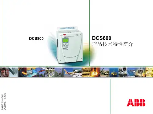
Welcome to the Large DC Drives Basic training module for the DCS800, ABB DC Drives.If you need help navigating this module, please click the Help button in the top right-hand corner. To view the presenter notes as text, please click the Notes button in the bottom right corner.After completing this module, you will knowwhat Large DC Drives arewhat DCS800 hard parallel is,what 12-pulse is,how to explain the differences between 12-pulse parallel, 12-pulse serial, serial sequential and quasi 12-pulse, andwhat master-followers, large field exciters, T-reactors, high speed DC-breakers and galvanic isolations are.Large DC Drives are used to drive the mechanics of very large installations for example mill stands, mine hoists, etc.The range of standard ABB converter modules is from 20 A to 5200 A with supply voltages from 230 VAC to 1000 VAC. It is possible to increase the power and torque of several different applications.The power and current can be increased by connecting several converter modules in hard parallel.The power and current can be increased by connecting two converter modules in 12-pulse parallel.The power and voltage can be increased by connecting two converter modules in 12-pulse serial.The power can also be increased by combining both hard parallel and 12-pulse.It is also possible to increase the power by using two or more motors. An example of this is that the motors are mounted on one shaft. All drives are controlled by one master. This configuration is called master-follower.A hard parallel DC Drive consists of two to four thyristor converter modules. The mains and the DC are connected in parallel.All modules are connected to a dedicated transformer. The only function of the transformer is to supply all of the converter modules, thus the name dedicated transformer.All converter modules are controlled by one paralleling master. Special hardware is used for this hard parallel master-slave communication.The current balancing between the converter modules is done by the DC and AC wiring. On the AC side, split and symmetrical cables, at least 3 m in length, have to be used. On the DC side, split cables of at least 3 m have to be used.Up to four converter modules can be connected in parallel. Thus, the power can be doubled, tripled or quadrupled by simply increasing the current.The current balancing between the converter modules is done by the DC and AC wiring. The AC wiring of each converter module is split on the secondary side of the transformer. All cables have to have the same length and must be routed symmetrically. The cables for DC wiring have to have the same length. No symmetrical routing is needed.The advantage of this design is the use of standard converter modules from the series production. Selected thyristors are not necessary anymore. This increases the quality, because converter modules from the series production can be used. Also, the spare part handling is easier, since standard spare parts can be used.Hard parallel is available for 6-pulse, 12-pulse parallel, 12-pulse serial, serial sequential and quasi 12-pulse.A 12-pulse DC Drive consists of two 6-pulse thyristor converter modules.The modules are connected to a dedicated three winding transformer. A three winding transformer has one primary winding and two secondary windings. Each of the secondary windings only supplies one of the 6-pulse converter modules, thus the name dedicated transformer.The phase shift between the secondary windings must be 30°electrical to achieve 12-pulse. This is possible with one of the secondary windings being in delta configuration and the other one being in star configuration. Thus 12-pulses will be seen on the primary side of the dedicated transformer and the current ripple of the DC-current.An example is a delta / delta / star transformer.The advantages of 12-pulse are:the reduced level of harmonics on the primary side of the transformer. Primarily the 5th and 7thharmonics are much lower compared to 6-pulse configurations.the power range is increased by either doubling the drive´s output current or its voltage. Theconfiguration is a 12-pulse parallel configuration if the output current is increased. It is a 12-pulse serial configuration, when the output voltage is increased.Since each 12-pulse drive consists of 2 converter modules it is possible to continue emergencyoperation with just one converter module.Compared to 6-pulse drives, the current ripple of 12-pulse drives is considerably lower. The motor efficiency increases due to the lower current ripple.All drives interfere with other equipment, because they produce harmonics on the AC side. To filter these harmonics, additional hardware is needed. For large drives this equipment is very expensive.An alternative to achieve a lower level of harmonics is the 12-pulse configuration. The 12-pulse configuration reduces the level of harmonics on the primary side of the transformer. Primarily the 5th and 7th harmonics are much lower compared to 6-pulse configurations. The total harmonic distortion is reduced by two thirds from over 36 % to fewer than 12 %.The characteristics of 12-pulse parallel are:two converter modules connected in parallel. Each converter module provides 50 % of the motor current. Thus, the power range is extended by doubling the DC current.The total harmonic distortion is reduced by two thirds by nearly eliminating the 5th and 7th harmonics.Compared to 6-pulse drives the current ripple of 12-pulse parallel drives is about 75 % lower. This reduces the motor noise level and increases the efficiency of the motor due to lower losses. This is an advantage especially for old motors which do not have sheeted bodies.Since each 12-pulse parallel drive consists of 2 converter modules, it is possible to continue emergency operation with only one converter. This converter module still supplies 100 % of the motor voltage but only 50 % of the motor current. Thus, it is possible to reach full speed with 50 % torque.The maximum mains voltage is 690 VAC for D5 converter modules and 1200 VAC for D6 and D7 converter modules.The characteristics of 12-pulse serial are:two converter modules connected in serial. Each converter module provides 50 % of the motor voltage.Thus, the power range is extended by doubling the DC voltage.The total harmonic distortion is reduced by two thirds by nearly eliminating the 5th and 7th harmonics.Compared to 6-pulse drives the current ripple of a12-pulse parallel drive is about 75 % lower. This reduces the motor noise level and increases the efficiency of the motor due to lower losses. This is an advantage especially for old motors which do not have sheeted bodies.Since each 12-pulse serial drive consists of 2 converter modules, it is possible to continue emergency operation with only one converter. This converter module still supplies 100 % of the motor current but only 50 % of the motor voltage. Thus, half speed with a maximum of 100 % torque is possible.The maximum mains voltage is 2 * 350 VAC for D5 converter modules and 2 * 600 VAC for D6 and D7 converter modules.The characteristics of serial sequential are:two converter modules connected in serial. Each converter module provides 50 % of the motor voltage.Thus, the power range is extended by doubling the DC voltage.The 30°phase shift on the secondary side of the dedicated transformer is not necessary.Due to the sequential type of firing pulses, the consumption of reactive power is reduced. This is important for large drives using high torques at low speeds.Since each serial sequential drive consists of 2 converter modules, it is possible to continue emergency operation with only one converter. This converter module still supplies 100 % of the motor current but only 50 % of the motor voltage. Thus, half speed with a maximum of 100 % torque is possible.The maximum mains voltage is 2 * 350 VAC for D5 converter modules and 2 * 600 VAC for D6 and D7 converter modules.The characteristics of quasi 12-pulse are:the reduced level of harmonics on the primary side of the transformer. This is one of the most significant advantages of 12-pulse especially since 12-pulse is mainly used for large drives.In a 12-pulse configuration the harmonics are suppressed on the DC side of the converter at the motor and on the primary side of the dedicated transformer. 12-pulse on the DC side reduces the losses of the motor. 12-pulse on the primary side of the transformer reduces the harmonics.In a quasi 12-pulse configuration the harmonics are only suppressed on the primary side of thededicated transformer. The DC motors run in normal 6-pulse configuration. Thus, less filtering and compensation hardware is needed on the high voltage side to suppress disturbances such as flickering.To increase the power even higher, 12-pulse and hard parallel configurations can be combined. Hard parallel is available for 6-pulse, 12-pulse parallel, 12-pulse serial, serial sequential and quasi 12-pulse.To increase the power of an installation, it is also possible to use more than one motor. All of these motors are controlled by a configuration called master -follower.For the master -follower configuration it is mandatory, that all motors run at the same speed and no speed difference between the motors is possible. Thus, all motors are, for example, mounted on one shaft.All drives are controlled by only one master. The other drives are followers and are either torque or window controlled.Standard ABB field exciters supply a maximum field current of 60 A. Large motors need higher field currents. To supply field currents up to 520 A, standard DCS800 converter modules are used. The standard converter module can be adapted to become a field exciter. This adaptation is done by means of parameters which are available in the standard firmware. So, to use a standard module as a field exciter, no hardware changes are needed in the converter module. Overvoltage protection is needed to protect the field circuit from damage.T-reactors are only used in 12-pulse parallel configurations. The 30 °phase shift between 12-pulse master and 12-pulse follower supply voltages generates an instantaneous voltage difference between the output voltages of both converters. The maximum amount of this difference is 50 % of the peak value of the supply voltage. The T-reactor absorbs this instantaneous voltage difference and provides the typical 12-pulse current to the DC-motor.ABB also provides customized T-reactors. The T-reactors are dimensioned depending on the line voltage and motor current.The T-reactors provided by ABB have a high overload capability and are much smaller than air-core reactors and are therefore much lower in cost.High speed DC-breakers are able to extinguish excessively high DC currents immediately. Thus, the motor can be protected against overcurrents causing damages to it, for example flash over at the commutator. Usually the high-speed DC-breaker trips itself when an overcurrent occurs.This is done by means of a fast magnetic overcurrent trip coil.It is also possible to trip the high-speed DC-breaker with a trip command from the drive. This trip signal is generated by motor or drive overcurrents, mains under voltage and excessively high current rise.To reduce the delay time before the high-speed DC-breaker is opened after a trip command from the drive, fast tripping relays are available.When using high speed DC-breakers, overcurrent trip become resettable, because the high-speed DC-breaker trips before other parts in the system -for example the fuse -become damaged.Thus, the availability of the whole drive increases.High speed DC-breakers are strongly recommended when using drives without AC breakers to ensure that the DC motors are protected against damage from overcurrent.ABB also provides high speed DC-breakers and integrates them into the drive's lineup.Usually the DC-and AC-voltage is measured via high ohmic resistors with a scaling of 1 MOhm per 100 Galvanic isolation is used to isolate the DC-and AC-voltage measurement circuits of the converter modules from dangerously high DC-and AC-voltages. Galvanic insulation is usually needed when either the supply voltage or the motor voltage is greater than 690 V.Galvanic isolation is used in both 6-pulse and 12-pulse systems.Only the AC-and DC-voltage measurement has to be galvanically isolated, because the current measurement is already isolated via current transformers -CTs for short.To isolate the AC-voltage measurement, a special isolation transformer for all three phases is needed. The DC-voltage measurement is isolated by means of a DC-DC transducer.The transformer and the DC-DC transducer are provided by ABB.Now you know what Large DC Drives using DCS800 hard parallel and 12-pulse are. Also, the differences between the different kinds of 12-pulse configurations should be clear. You should also know about master-follower, large field exciters, T-reactors, high speed DC-breakers and galvanic isolation.Here are some related documents for further training and additional references.Thank you for your attention. You may now go ahead and move on to the next unit.。