西门子549613MEC控制器
- 格式:doc
- 大小:34.00 KB
- 文档页数:6

西门子电动三通温控阀·VXF61西门子电动三通阀·VXF529西门子三通温控阀·VXF45西门子三通调节阀·VXF42西门子三通温控阀·VXF41西门子三通阀·VXF40西门子三通温控阀·VXF31西门子电动三通温控阀西门子蒸汽调节阀·VVF529西门子蒸汽调节阀·VVF52西门子蒸汽调节阀·VVF45西门子蒸汽调节阀·VVF42西门子蒸汽调节阀·VVF41西门子蒸汽调节阀西门子温控阀·西门子温控阀·西门子电动温控阀·西门子电动式温控阀(进口)·西门子电动温控阀阀体·西门子三通水阀·西门子电动三通温控阀·vvi46.20西门子温控阀·VXG44三通温控阀·智能型电动温控阀·VVF40西门子温控阀·VVF31西门子温控阀·VVF529西门子蒸汽温控阀·VVF45西门子蒸汽温控阀·VVF42西门子蒸汽温控阀·VVF41西门子蒸汽温控阀·VVF61西门子温控阀·VVF529西门子温控阀·VVF52西门子温控阀·VVF45西门子温控阀·VVF41西门子温控阀·西门子蒸汽温控阀西门子温度调节阀·西门子温度调节阀·西门子蒸汽调节阀·西门子三通调节阀·VXG44电动调节阀·VXF31西门子三通调节阀·VXF40西门子三通调节阀·VXF42西门子三通调节阀·VXF45西门子三通调节阀·VXF529西门子三通调节阀·VVF529西门子温度调节阀·VVF45西门子温度调节阀·VVF42西门子温度调节阀·VVF41西门子温度调节阀·VVF40西门子温度调节阀·VVF31西门子温度调节阀·智能型电动调节阀·电动压力调节阀·西门子调节阀·西门子压差调节阀·西门子压力调节阀·动态平衡电动调节阀西门子三通调节阀·VXF529西门子三通调节阀·VXF45西门子三通调节阀·VXF42西门子三通调节阀·VXF41西门子三通调节阀·VXF40西门子三通调节阀·西门子三通调节阀自力式温控阀·自力式温控阀·自力式三通温控阀·自力式蒸汽温控阀·自力式冷却阀自力式温度调节阀·自力式温度调节阀·自力式蒸汽调节阀·自立式三通温度调节阀西门子电动执行器·sua21电动执行器·skc62电动执行器·skb62电动执行器·skd62电动执行器·sqx62电动执行器·SFA21电动执行器·西门子电动蝶阀执行器·西门子风阀执行器西门子温度控制器·西门子rwd62温度控制器·西门子rwd68温度控制器西门子温度传感器·西门子qam2120温度传感器·西门子qac22温度传感器·西门子qae2121温度传感器西门子压力传感器·西门子QBE2000压力传感器西门子电动减压阀·西门子蒸汽减压阀·西门子电动减压阀。

西门子plc型号含义说明西门子plc型号编制通常所指的是订货号。
以6ES7 221-0BA23-0xA0为例:6-自动化系统系列;S7-S7系列,S5-S5系列;2-200系列,3-300系列,4-400系列;2-DI/DO,1-CPU,3-AI/AO,4-通信模块,5-功能模块;1-输入,2-输出,3-输入/输出(对于数字量);OBA-输入/输出电压等级、类型、点数等,具体要看产品说明;23-版本;0xA0-此数值代表不同功能的模块。
西门子plc根据规模和性能的大小,主要有S7-200,S7-300和S7-400三种,下面就简单介绍一下该三种产品的一些特性。
1、S7-200针对低性能要求的摸块化小控制系统,它最多可有7个模块的扩展能力,在模块中集成背板总线,它的网络联接有rs-485通讯接口和profibus两种,可通过编程器pg访问所有模块,带有电源、cpu和i/o的一体化单元设备。
其中的扩展模块(em)有以下几种:数字量输入模块(di)——24vdc和120/230vac;数字量输出(do)——24vdc和继电器;模拟量输入模块(ai)——电压、电流、电阻和热电偶;模拟量输出模块——电压和电流。
还有一个比较特殊的模块-通讯处理器(cp)——该块的功能是可以把s7-200作为主站连接到as-接口(传感器和执行器接口),通过as-接口的从站可以控制多达248个设备,这样就可以显著的扩展s7-200的输入和输出点数。
2、S7-300相比较s7-200,s7-300针对的是中小系统,他的模块可以扩展多达32个模块,背板总线也在模块内集成,它的网络连接已比较成熟和流行,有mpi、工业以太网,使通讯和编程变得简单,选择性也比较多,并可借助工具进行组态和设置参数。
s7-300的模块稍微多一点,除了信号模块(sm)和200的em模块同类型之外,它还有接口模块(im)——用来进行多层组态,把总线从一层传到另一层;占位模块(dm)——为没有设置参数的信号模块保留一个插槽或为以后安装的接口模块保留一个插槽;功能模块(fm)——执行特殊功能,如计数、定位、闭环控制相当于对cpu功能的一个扩展或补充;通讯处理器(cp)——提供点对点连接、profibus和工业以太网。

iF product design award 2012:SAX and SAL产品概览Acvatix 阀门执行器─经济高效的HVAC 系统的决定性组成部件以多年的实践经验、广泛的专业知识和先进的技术为依托,西门子推出了AcvatixTM系列阀门和执行器产品,为暖通水力系统提供理想的解决方案。
这些阀门执行器主要应用于暖通系统中的冷热源、能源分配及末端控制,并可用于区域供热。
因此,Acvatix能够满足HVAC领域以及制冷和工业应用的各种需要。
无论是单户住宅还是公寓,无论是现代办公大楼里复杂的空调还是流量非常大的设备,Acvatix阀门执行器都以高质量和长寿命著称。
他们不仅让您感到舒适、安宁,还可以在能源优化使用、项目改造中助您一臂之力。
适用于各种应用的阀门执行器产品只有机组内每个设备都能可靠、精确的运转时,HVAC 和制冷系统才能正常的工作。
来自西门子的Acvatix 产品线根据您的需要、介质类型和应用类型,总能为您提供合适的阀门执行器:- 用于小型、中型和大型HVAC 和制冷系统的阀门执行器- 用于房间、区域等末端控制的阀门执行器- 两通和三通座阀、蝶阀- 法兰、螺纹和焊接连接- 用于高精度、复杂控制系统的电磁调节阀- 带调节功能和3位或开/关控制信号的执行器地板采暖,辐射采暖TEVA 产品线,见第16页利用散热器控制区域温度TEVA 产品线,见第15和16页生活热水混合系统反应迅速的电磁调节阀, 见第5页法兰和螺纹连接的阀, 见第7-10页生活热水存储罐反应迅速的电磁调节阀,见第5页法兰和螺纹连接的阀, 见第7-10页法兰和螺纹连接的阀, 见第7-10页关闭功能蝶阀,见第13页区域供热分站法兰和螺纹连接的阀, 见第7-10页关闭冷却水塔见第13页控制风机盘管装置TEVA 产品线,见第16页冷吊顶TEVA 产品线,见第16页控制终端装置TEVA 产品线,见第16页用于空气调节设备的制冷盘管反应迅速的电磁调节阀,见第5页法兰和螺纹连接的阀,见第7-12页用于空气调节设备的供暖盘管法兰和螺纹连接的阀,见第7-12页冷冻水环路反应迅速的电磁调节阀,见第5页法兰和螺纹连接的阀,见第7-13页冷却水环路反应迅速的电磁调节阀,见第5页法兰和螺纹的阀,见第7-13页■ 实现能源优化■产品种类多样,适合于各种应用■ 便捷选择阀门执行器■高效配送- 工作电压为AC / DC 24 V 或AC 110 / 230 V 的执行器- 大量专利技术应用于各阀门或执行器,优化系统控制便捷选型西门子为您提供了各种阀门执行器的选型工具,阀门选型尺,技术资料和在线工具。
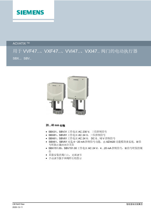
20…40 mm行程∙SBX31、SBV31工作电压 AC 230 V,三位控制信号∙SBX81、SBV81工作电压 AC 24 V,三位控制信号∙SBX61、SBV61工作电压 AC 24 V, DC 0…10 V控制信号∙SBX61、SBV61可选4…20 mA控制信号功能,由AZX420功能模块来实现,断信号时执行器回到全关位∙SBX151.00、SBV151.00工作电压AC 24 V,4…20 mA控制信号,断信号时保持阀位∙直接安装在阀门上,无需调节∙手动调节扳手和阀杆行程指示用于西门子二通阀 VVF47..、VVI47和三通阀VXF47.. VXI47..系列型号的阀门执行器,驱动行程为 20 mm和 40 mm,在暖通空调系统中作为控制阀使用。
产品型号物料编号定位信号行程驱动力工作电压 [V]运行时间[s]手动操作SBX61S55160-A100DC 0…10 V20 mm 700 N AC 24 V120手动调节扳手SBX81S55160-A101三位SBX31S55160-A102AC 230 V SBX151.00S55160-A1084…20 mA AC 24 VSBV61S55160-A103DC 0…10 V40 mm 1600 N AC 24 V180手动调节扳手SBV81S55160-A104三位SBV31S55160-A105AC 230 VSBV151.00S55160-A1094…20 mA AC 24 V 附件产品型号物料编号说明SBX31SBV31SBX81SBV81SBX61SBV61SBX151.00SBV151.00AZX420 S55845-Z120功能模块--最多1个-示例产品型号订货号说明数量SBX61S55160-A100执行器1AZX420S55845-Z120功能模块1交付执行器、阀门和附件分开包装和供货。
2二通阀关于执行器的详细信息,请参阅“电动执行器 SBX..、SBV..”的用户手册,该文档的编号是CB1P4519en。

西门子电动调节阀安装使用手册济南百通控制设备有限公司我们愿以优质的产品、热情的服务与您携手合作。
为了使我们的产品更好的为您服务,请您详细阅读以下内容。
一、调节阀的工作原理热媒介质流过阀门,经过换热器把被加热介质升温,温度传感器随着被加热介质的温度变化,将信号送至控制器,与设定温度比较运算后将4-20毫安或0-10伏信号送至执行器控制阀门的开度,使热媒介质流量发生变化。
温度的细微变化将使传感器作出响应,改变热媒介质流量,精确控制被加热介质的温度。
二、安装要求安装前请仔细阅读本使用手册,如有疑问请咨询专业技术人员。
不按规程安装操作都可能导致设备损坏或影响使用效果。
1、本产品在出厂前经过严格的检测,尽管如此,在安装前请务必进行检查。
2、请按订货及送货装箱单核实数量及型号。
3、请按上述数量配置进行检验,检查在运输过程中是否有损坏。
三、安装指导图1、安装步聚:(1)阀体应水平安装在一次热媒的入口处,阀杆朝上,确保执行器可垂直于水平面安装。
(2)阀体前应安装过滤器,且直接与阀体对接,选用高目数过滤器。
(3)阀前后安装手动截止阀。
(4)阀侧面应安装旁通,并安装手动截止阀。
(5)若阀前蒸汽压力过高,应安装减压阀,将蒸汽调至设计或最佳工作范围内。
2、安装方式:(正确安装)(错误安装)3、安装要求:(执行器安装):1、将阀杆向上拉起。
2、将执行器安装于阀体上。
3、先用内六方或其它合适的工具预固定执行器底部于阀体连接环槽上。
4、旋转执行器手动旋钮(SQX、SKD系列)或手动摇柄(SKB、SKC系列)将执行器连接凹槽对正(注意:SKB、SKC系列要先将执行器下部连接内螺纹活节拆下,并将连接活节套于阀杆上。
)(传感器安装)(1)在换热器出口处附近开孔,焊丝座。
丝座要求:G1/2``管螺纹,内丝。
(2)丝座建议加工尺寸接管径匹配:(3)将传感器底部螺纹缠绕四氟胶带,沿顺时针方向固定于丝座上。
注意:密封需严密,防止漏水。
(电控箱安装):(1)选择适当地点,一般为便于观察操作的墙面。


CE1N1633en Siemens Building Technologies1633Room Unit forSynco™ 700 ControllersQAW740 Konnex bus connectionMultifunctional, digital room unit for simple remote control of Synco™ 700 controllers.Use Room unit in combination with a Synco™ 700 controller for plant in:• Office and administrative buildings • Business and sales premises • Schools • Hospitals• Factory buildings and workshops • Apartment buildingsFor use with Synco™ 700 controllers for heating, ventilation or air conditioning (HVAC) systems. Only usable for systems with Konnex (KNX) communication.Functions • Remote control of a Synco™ 700 controller • Room temperature measurement • Communication via KonnexUseApplicationMain functions•Relative temperature setpoint adjustment•Preselection of operating mode with Mode button•Timer function with timer button•Display of operating level, temperatures, timer function and alarmType summaryTyp Designation Compatible withQAW740 Roomunit Synco™700controllerNot suitable for use with the Synco™ RXB controller.Technical designcan be readjusted by ± 3 °C (± 6 °F), which is then transmitted to the controller. Thebasic setting of the Comfort setpoint is made at the controller itself. During setting withthe knob, the display changes to the correction value that is set. If no further settingsare made, the setting is acknowledged by the return of the basic display with the actualroom temperature value after a delay of 4 seconds.The Mode button is used to switch between automatic and manual mode. Thisefficiently matches the room temperature to the respective room use.The change of operating mode with the Mode button can automatically be reset bymaking on the serviced level. In that case, a reset back to automatic mode is madeafter the selected period of time (1…99 Std.) has elapsed. However, this function is notactivated as standard and the selected operating mode is maintained continuously.The timer function starts an adjustable time period during which comfort mode issustained. This function is started by pressing the timer button, and the required periodof time for the function is adjusted with the setting Knob, the increments being 15minutes. When starting the function, the time period used last will appear. A maximumadjustment of 20 hours from the setting time is possible. The room unit transmits theset adjustment to the controller via the bus, but the actual room control program in thecontroller remains unchanged.In case of deviations from the displayed value, the measured room temperature valuecan be adjusted in the range –4.5…4.5 °C. The room unit transmits the resultant actualvalue via the bus and indicates it on the display.The display in °C or °F can be selected.Operator functionsNoteComfort setpointrelativeMode buttonTimer functionMeasured valuereadjustement ofroom temperatureUnit2/63/6Short-circuit or open-circuit of the room sensor isindicated by a bell symbol on the display. The room unit transmits such errors via the bus.The bell symbol also indicates alarms that the assigned controller transmits to the room unit via the bus. The actual temperature value remains on display. In case of a device address conflict, the display changes to this setting.The room unit has a device address and a geographical zone, which it uses for communication with the controller and other devices on the bus system. Therefore, address assignment must be planned for data to be transmitted correctly.The room unit automatically provides the device address the first time it is powered up, or it searches for a free device address at the push of a button. However, manual changes are also possible.The geographical zone (apartment) must match that of the controller, so it must be entered during installation.Bus traffic, which is mainly influenced by the frequency of room temperature measured values, can be limited using the room temperature threshold function. The device does not transmit a measured value until it exceeds the threshold value.The room unit is intended for easy mode, but is capable of Konnex S-mode integration. Therefore, consult the Konnex bus system description for planning and installation.The service level and expert level are used for commissioning. The procedure is described in Installation Instructions CE1G1633.Mechanical design The unit consists of the following components:• Housing with integrated electronics and operating elements • Base for wall mounting with the connection terminalsFault status messagesCommunicationDevice address (d)The geographical zone (A)Bus trafficKonnexCommissioningRoom unitOperating elementsTimer button Display KnobMode-button4/6Technical data Konnex bus Type of interface Konnex-TP1Transceiver TP-UART Baud rate 9.6 kBit/s Cuttent draw bus 7.5 mA Bus loading number (SBT) 1.2For more information about the Konnex bus, refer to the following pieces of documentation: Data Sheet CE1N3127en, Basic Documentation CE1P3127en Konnex bus As per data sheet CE1N3127en Type of cable 2-wire, unshielded twisted pair; connectionsnon-interchangeable as per Data Sheet CE1N3127enSafety class III to EN 60730(when mounted correctly)Housing protection standard IP 20 to EN 60529Contaminationenvironment to EN 60730 Operation IEC 721-3-3 class 3K 5Temperature 0…50 °C (noncondensing) Humidity < 85 % rh Transport IEC 721-3-2 class 2K 3Temperature –25...70 °C Humidity < 95 % rh Storage IEC 721-3-1 class 1K 3Temperature –25...70 °CEMC directive 89/336/EECImmunity EN 50082-1, EN 50082-2, EN 60730-1EN 50090-2-2EmissionsEN 50081-1, EN 50081-2, EN 50090-2-2 Low-voltage directive 73/23/EEC– Electrical safety EN 60730-1, EN 60730-2-9Measuring range0…45 °C Time constant 13 min Software class A to EN 60 730Weightapprox. 0,115 kg InterfacesWiring connectionsProtectionEnvironmentalconditionsStandardsRoom temperature measurement Other features5/6Notes• The products may only be used in building services plant and applications as described above• When using the products, all requirements specified under ”Technical data” must be observed• The local regulations for electrical installation must be complied with• Montage im Hauptaufenthalts– bzw. Referenzraum• The place of installation should be chosen so that the sensor can capture the room temperature as accurately as possible, without being affected by direct solar radiation or other heating or cooling sources• Mounting height is about 1.5 meters above the floor• The basic principles of the Konnex bus system must be observed (see documents CE1N3127 and CE1P3127)• The unit can be fitted to most commercially available recessed conduit boxes ordirectly on the wall• Wall mounting with base• The controller must not be exposed to dripping water• For the electrical installation, the local safety regulations and standards must be complied with• Installation and operating instructions are enclosed with each deviceConnection diagram1 2 3 4 5 6 CE+ CE- - - - - Konnex TP1 (non-interchangeable) Konnex TP1 (non-interchangeable) - - - -1345622284Z 40Product liabilityEngineeringInstallationInstallation and operationDimensions©2003 Siemens Building Technologies Ltd.Subject to alteration6/6。

2100RTN…STS61… VEN…AVN15-12SSA…STA…VPD…AVN15A16Product Range OverviewSmall Valves, Actuators + Accessoriesfor radiator, floor heating and chilled ceiling applicationsSelf-contained thermostatic actuators RTN… without auxiliary power•CEN-certified and tested to DIN EN215 part 1•Absolute noiseless actuator technology• Long service life•Manual setpoint adjustment, min. and max. limitationFavorably priced thermal actuators STA…, STS61… for demanding requirements•Absolute noiseless actuator technology• Long service lifeElectromotoric actuators SSA… for the most demanding requirements•Automatic detection of valve stroke• Long service life• Low noise•Plug-in connecting cableRF-controlled actuator SSA955 for radiator valves•For integration into the Siemens Synco 900 systemPreadjustable radiator valves VDN…, VEN…, VUN…•CEN-certified and tested to DIN EN215 part 1•Insert can be replaced while plant is under pressurePressure compensated radiator valves VPD…, VPE… (MCV) for perfect hydraulicbalancing• Solves noise problems•No line balancing valves required•No hydraulic balancing required because of automatic pressure compensation•Creates comfort and saves energyVarious mounting accessories•Simple and fast mounting•High operation safety.CE1N2100enBuilding TechnologiesEquipment combinations: Thermostatic and electronic actuators, valves and fittings2/63/6Accessories For mounting• thermostatic actuators RTN… • electromotoric actuators SSA… • RF-controlled actuator SSA955 • thermal actuators STA… • thermal actuators STS61…on radiator valves of other manufacturer according to table:Notes1) Oventrop has been using M30 x 1.5since 2001, requiring no adapter 2) Not to be used with RTN...3) TA (Heimeier) has been using M30 x1.5 since 2003, requiring no adapterConnection (M30 x 1.5) on valves of other manufacture, without adapter • Heimeier • Junkers• Honeywell Braukmann • MNG• Cazzaniga• Oventrop M30 x 1.5 (as of 2001) • TA-Type TBV-C • Beulco newThe sealing insert is suited for use with all radiator valves of the ranges VPD… and VPE….Adapter (AV…)Differential pressure overflow valves VS9…Sealing insert AV100-VP14/6Type reference (alphabetical)Type reference DescriptionG [in]DesignData sheetADN10 3/8ADN15 1/2ADN20 3/4straight AEN10 3/8 AEN15 1/2AEN20Lockshield valve 3/4angle N2107ATN1 Partner clip ATN2 Removal protection ATN3 Manual knob ATN4 Manual knob AVN1 Valve insertAVN10-12 3/8 Tube ∅ 12 mmAVN15-12 1/2 Tube ∅ 12 mmAVN15-14 1/2 Tube ∅ 14 mm AVN15-15 1/2 Tube ∅ 15 mmAVN15-16 Fittings for copper and steel pipes 1/2 Tube ∅ 16 mm AVN15P12 1/2 Tube ∅ 12 x 1.1 mmAVN15P14 Fittings for Pex plastic tubing 1/2 Tube ∅ 14 x 2 mm AVN15A14 1/2 Tube ∅ 14 x 2 mmAVN15A16 Fittings for Alupex tubing 1/2 Tube ∅ 16 x 2 mm AV51…AV61Adapter for valves of other manufacture N2100 RTN51… Thermostatic actuatorRAL 9016white glossy appearanceRTN71 Thermostatic actuator with remote sensor RTN81 Thermostatic actuator with remote adjusterN2111SSA31… Electromotoric actuator AC 230 V SSA81… Electromotoric actuator AC 24 V SSA61… Electromotoric actuator AC / DC 24 V N4893 SSA955 RF-controlled actuator SSA955 Battery-powered (LR6 / AA) N2700 STA21… Thermal actuator AC 230 V STA71… Thermal actuator AC / DC 24 V N4877 STA72E… Thermal actuator AC / DC 24 V N4875 STS61…Thermal actuatorAC 24 VN4880 VDN110 3/8VDN115 1/2VDN120 3/4straight, DIN N2105 VDN210 3/8 VDN215 1/2VDN220Valve3/4straight, NF N2106 VEN110 3/8VEN115 1/2VEN120 3/4angle, DIN N2105 VEN210 3/8VEN215 1/2VEN220 3/4angle, NF VUN210 3/8 VUN215 Valve1/2 reverse angle, NFN21065/6VDN10M 3/8VDN15M 1/2VDN20M 3/4straight VEN10M 3/8 VEN15M 1/2VEN20M Manual valve 3/4 angle N2104VPD110A-45 VPD110A-90 VPD110A-145 3/8VPD115A-45 VPD115A-90 VPD115A-145 1/2VPD110B-60 VPD110B-120 VPD110B-200 3/8VPD115B-60 VPD115B-120 VPD115B-200 1/2straight, DINVPE110A-45 VPE110A-90 VPE110A-145 3/8VPE115A-45 VPE115A-90 VPE115A-145 1/2VPE110B-60 VPE110B-120 VPE110B-200 3/8VPE115B-60 VPE115B-120 VPE115B-200 Mini-Combi-Valve (MCV)1/2angle, DINN2185VPD210A-45 VPD210A-90 VPD210A-145 3/8VPD215A-45 VPD215A-90 VPD215A-145 1/2VPD210B-60 VPD210B-120 VPD210B-200 3/8VPD215B-60 VPD215B-120 VPD215B-200 1/2straight, NFVPE210A-45 VPE210A-90 VPE210A-145 3/8VPE215A-45 VPE215A-90 VPE215A-145 1/2VPE210B-60 VPE210B-120 VPE210B-200 3/8VPE215B-60 VPE215B-120 VPE215B-200 Mini-Combi-Valve (MCV)1/2angle, NFN21856/6VS920 3/4VS932 Differential pressure overflow valve1 1/4VS920F 3/4 VS932FDifferential pressure overflow valve for district heating house substations1 1/4angle N2181Technical notes NO valves• fully open when de-energized (normally open). • Valve stem extended.Radiator valves like VDN…, VEN…, VUN…, VPD… or VPE… are usually NO valves.NC valves• Closed when de-energized (normally closed). • Valve stem extended.Small valves like V…P47… are usually NC valves.NO function • Actuator stem is retracted when de-energized. • Valve is open.NC function• Actuator stem is extended when de-energized. • Valve is closed.The thermostatic RTN… actuators control the heat demand. They control the water flow by opening and closing the radiator valves.• With increased heat demand the actuator stem retracts and steadily opens the radia-tor valve.• With decreasing heat demand the actuator stem extends and steadily closes the radiator valve.STA…Radiator valves (NO valves) actuator de-energized • VDN…, VEN…, VUN… • VPD…, VPE…closed (NC function)Use STA72E actuators for DESIGO RX…The STS61… thermal actuator is driven by a DC 0...10 V positioning signal. The actua-tor can be operated in two directions of actions (Y or Y ) and can therefore be used with radiator NO valves as well as with small valves NC.OperationBreakdownDirection of action DC 0…10 V Actuator stem Valve behavior Actuator de-energizedY increasing Stem retracts NO opens NO radiator valve or MCV closedY increasing Stem extends NC opens NC small valves openThe electromotoric the actuator is driven by DC 0…10 V positioning signal or by a 3-position signal. The description of operation in this document applies to the valve versions which are fully open when de-energized (NO). • Voltage at Y1: Stem retracts Valve opens • Voltage at Y2:Stem extends Valve closes • No voltage at Y1 and Y2:Actuator maintains its current position• The valve opens / closes in proportion to the control signal at Y. • At DC 0 V, the valve is fully closed (A Æ AB), stem extended• When power supply is removed, the actuator maintains its current position.NO, NC valvesValve and actuator combinationsRTN…STA…, STP…AttentionSTS61…SSA31…, SSA81…3-Position control signalDC 0...10 V©2006 - 2008 Siemens Switzerland Ltd Subject to alteration。

SIMOVERT MASTERDRIVES 矢量控制装机装柜型变频器(AC – AC)使用说明书此使用说明书仅适用于装置软件版本V3.2。
我们保留更改功能、技术数据、标准、附图及参数的权利。
西门子电气传动有限公司(SEDL)目前只提供本使用说明书中:- 3AC 380V~480V MASTERDRIVES 6SE70产品及相应选件- 3AC 380V~480V MASTERDRIVES 6SE71产品及相应选件- 3AC 660V~690V MASTERDRIVES 6SE71产品及相应选件用户如需要其它电压等级的产品或有特殊要求,请与当地西门子公司办公室联系。
西门子电气传动有限公司保留更改本使用说明书的权利,如有更改,恕不通知。
注册商标:SIMOVERT03.03序言感谢您使用西门子的传动产品!西门子变频传动产品SIMOVERT MASTERDRIVES自在中国市场推出以来,与西门子公司的其它产品一样,得到了广大用户的认同和使用。
新推出的SIMOVERT MASTERDRIVES Vector Control系列变频传动产品具有更大允许电压波动范围、更小的体积、更强的通讯能力并可同直流传动系统100%的兼容。
我们相信,新系列产品将会在多种工业、商用及民用领域中得到更广泛的应用。
为此,我们对西门子公司的广大用户及关心西门子公司产品的人士表示由衷的感谢!为了用户能够更方便的使用西门子公司SIMOVERT MASTERDRIVES Vector Control变频传动产品,我们根据原英文版使用说明书,翻译出版了这套中文版的使用说明书。
这套使用说明书仅适用于装置软件版本V3.2。
随着产品技术的不断更新,我们将及时更新中文使用说明书内容,以方便您的使用。
限于篇幅,本说明书简单介绍了产品的基本信息,如您需要更进一步的了解,请查阅“SIMOVERT MASTERDRIVES矢量控制使用大全”(中文版订货号6SE7085-0QX60)的有关章节,如EMC 导则、通讯、功能图、参数表等。

技术规范图1. 模块式设备控制器说明模块式设备控制器(MEC)是APOGEE现场管理和控制系统的组成部份,是一个高性能的直接数字控制器(DDC)。
MEC在不依靠较高层处理机的情形下,可以独立工作和联网以完成复杂的控制、监视和能源管理功能,而不需依赖更高层的处理器。
MEC可以连接楼层级网络(FLN)设备并提供中央监控功能。
最多有100个MEC控制器或现场处理机,可在点对点(Peer-to-Peer)网络上通讯。
FLN上可运行P1或LonTalk协议。
特点●可与其它层级的处理机互相搭配,以符合应用的需求●通过扩展模拟量/数字量模块设备,可增加监控点数●结合软件与硬设备配合控制应用●以先进的 PID 算法,精准的将 HVAC 控制在最小的变动范围内●具备 DDC 及内置的能源管理程序●具有管理多种报警、历史及趋势记录的收集、操作控制和监控功能●经由集线器(HUB)可将信息传送给远程打印机、寻呼接收机和工作站●可选配手动/停止/自动 (HOA) 切换开关●与LonWorks 网络兼容的选项图2. 310系列模块式设备控制器结构硬件MEC 控制器具备几种系列,皆具有灵活性、扩展性。
MEC 控制器-1XX 系列除了系统管理功能外,可控制 32 个输入/输出监控点MEC 控制器-2XX 系列除了控制 32 个输入/输出监控点外,还通过点模块扩展模拟量和数字量的监控点。
这种特性可使MEC 的监控点得以扩充,并提供终端点靠近负载处的经济方式。
MEC 控制器-3XX 系列这一系列控制器提供输入/输出监控点,并提供模拟/数字监控点模块与APOGEE 对调制解调器自动拨号的功能。
中央控制器可远程控制MEC 。
MEC 控制器—2XXF 和3XXF 系列这一系列控制器具备更强大的功能和扩展内存,能联接3条楼层级网络(FLN )和总共96个楼层级网络设备。
MEC 控制器—2XX L 和3XXL 系列这一系列控制器比2XXF 和3XXF 系列有更强的功能并且支持LonWorks 。

Technical Specification SheetDocument No. 149-454July 1, 2013 Siemens Industry, Inc. Page 1 of 8PXC Compact SeriesFigure 1. PXC Compact Series Controllers(PXC-24 and PXC-36 shown.)DescriptionThe PXC Compact Series (Programmable Controller–Compact) is a high-performance Direct Digital Control(DDC) supervisory equipment controller, which is anintegral part of the APOGEE® Automation System.The PXC Compact Series offers integrated I/O basedon state-of-the-art TX-I/O™ Technology, whichprovides superior flexibility of point and signal types,and makes it an optimal solution for Air Handling Unit(AHU) control. The PXC Compact operates stand-alone or networked to perform complex control,monitoring, and energy management functions withoutrelying on a higher-level processor.The PXC Compact Series communicates with otherfield panels or workstations on a peer-to-peerAutomation Level Network (ALN) and supports thefollowing communication options:∙ Ethernet TCP/IP∙P2 RS-485The PXC Compact is available with 16, 24, or 36 pointterminations. Selected models in the Compact Seriesprovide the following options:∙Support for FLN devices.∙An extended temperature range for the control ofrooftop devices.∙Support for Island Bus, which uses TX I/Omodules to expand the number of pointterminations.Features∙DIN rail mounted device with removable terminalblocks simplifies installation and servicing.∙Proven program sequences to match equipmentcontrol applications.∙Built-in energy management applications and DDCprograms for complete facility management.∙Comprehensive alarm management, historicaldata trend collection, operator control, andmonitoring functions.∙Sophisticated Adaptive Control, a closed loopcontrol algorithm that auto-adjusts to compensatefor load/seasonal changes.∙Message control for terminals, printers, pagers,and workstations.∙Highly configurable I/O using Siemens state-of-the-art TX-I/O™ Technology.∙HMI RS-232 port, which provides laptopconnectivity for local operation and engineering.∙Extended battery backup of Real Time Clock.∙Persistent database backup and restore within thecontroller.∙Optional HOA (Hand/Off/Auto) module forswappable and configurable HOA capability.∙Optional extended temperature range for rooftop installation.∙Optional peer-to-peer communications over industry-standard 10Base-T/100Base-TX Ethernet networks.∙Optional support for FLN devices.∙Optional support for P1 Wireless FLN.∙Optional operation as a P1 FLN device with default applications.∙Optional support for Virtual AEM.∙PXM10T and PXM10S support: Optional LCD Local user interface with HOA (Hand-off-auto)capability and point commanding and monitoringfeatures.The Compact SeriesIn addition to building and system management functions, the Compact Series includes several styles of controllers that flexibly meet application needs.PXC-16The PXC-16 provides control of 16 points, including 8 software-configurable universal points.Point count includes: 3 Universal Input (UI), 5 Universal I/O (U), 2 Digital Input (DI), 3 Analog Output (AOV), and 3 Digital Output (DO).PXC-24The PXC-24 provides control of 24 points, including 16 software-configurable universal points.Point count includes: 3 Universal Input (UI), 9 Universal I/O (U), 4 Super Universal I/O (X), 3 Analog Output (AOV), 5 Digital Output (DO).PXC-36The PXC-36 provides control of 36 local points, including 24 software-configurable universal points. Point count includes: 18 Universal I/O (U), 6 Super Universal I/O (X), 4 Digital Input (DI), and 8 Digital Output (DO).The PXC-36 offers the flexibility of expanding the total point count through a self-forming island bus. With the addition of a TX-I/O Power Supply, up to 4 TX-I/O modules can be supported. For more information, see the TX-I/O Product Range Technical Specification Sheet (149-476). Available OptionsThe following options are available to match the application:Ethernet or RS-485 ALNSupport for APOGEE P2 ALN through TCP/IP orRS-485 networks.FLN Support∙The PXC-24 “F32” models support up to 32 P1 FLN devices when the ALN is connected toTCP/IP.∙The PXC-24 “F” models with an FLN license support up to 32 P1 FLN devices when the ALN isconnected to TCP/IP.∙The PXC-36 with an FLN license supports up to 96 P1 FLN devices when the ALN is connected toRS-485 or TCP/IP.∙ A Wireless FLN may also be used to replace the traditional P1 FLN cabling with wirelesscommunication links that form a wireless meshnetwork. Additional hardware is required toimplement the Wireless FLN.For more information about FLN support, contact your local Siemens Industry representative.P1 FLN OperationThe PXC-16 and PXC-24 can be configured as a programmable P1 FLN device. In the P1 FLN mode, the PXC Compact functions as an equipment controller with customized programming and default applications.Virtual AEM SupportThe Virtual AEM license allows the PXC Compact to connect an RS-485 APOGEE Automation Level Network or individual field panels to a P2 Ethernet network without additional hardware.Extended Temperature OperationThe "R" models of the PXC Compact Series support extended temperature operation, allowing for rooftop installations.Field Panel GOThe PXC-36 supports Field Panel GO.The Field Panel GO license provides a Web-based user interface for your APOGEE® Building Automation System. It is an ideal solution for small or remote facilities with field panels on an Ethernet Automation Level Network (ALN).Page 2 of 8 Siemens Industry, Inc.HardwareThe PXC Compact Series consists of the following major components:∙ Input/Output Points∙ Power Supply∙ Controller ProcessorInput/Output Points∙The PXC Compact input/output points perform A/D or D/A conversion, signal processing, pointcommand output, and communication with thecontroller processor. The terminal blocks areremovable for easy termination of field wiring.∙The Universal and Super Universal points leverage TX-I/O™ Technology from SiemensIndustry to configure an extensive variety of pointtypes.∙Universal Input (UI) and Universal Input/Output (U) points are software-selectable to be:- 0-10V input-4-20 mA input- Digital Input-Pulse Accumulator inputs-1K Ni RTD @ 32°F (Siemens, JohnsonControls, DIN Standard)-1K Pt RTD (375 or 385 alpha) @ 32°F-10K NTC Thermistor (Type 2 and Type 3) @ 77°F-100K NTC Thermistor (Type 2) @ 77°F-0-10V Analog Output (Universal Input/Output (U) points only)∙Super Universal (X) points (PXC-24 and PXC-36 only) are software-selectable to be:- 0-10V input-4-20 mA input- Digital Input-Pulse Accumulator inputs-1K Ni RTD @ 32°F (Siemens, JohnsonControls, DIN Standard)-1K Pt RTD (375 or 385 alpha) @ 32°F-10K NTC Thermistor (Type 2 and Type 3) @ 77°F-100K NTC Thermistor (Type 2) @ 77°F- 0-10V Analog Output-4-20 mA Analog Output-Digital Output (using external relay)∙Dedicated Digital Input (DI) points (PXC-16 and PXC-36 only) are dry contact status sensing. ∙Digital Output (DO) points are 110/220V 4 Amp (resistive) Form C relays; LEDs indicate the status of each point.∙All PXC Compact Series models support 0-10 Vdc Voltage Analog Output circuits.∙On PXC-24 and PXC-36 models, the Super Universal circuits may be defined as 4-20 mAcurrent AO.Power Supply∙The 24 volt DC power supply provides regulated power to the input/output points and activesensors. The power supply is internal to the PXCCompact housing, eliminating the need forexternal power supply and simplifying installationand troubleshooting.∙The power supply works with the processor to ensure smooth power up and power downsequences for the equipment controlled by the I/O points, even through brownout conditions. Controller Processor∙The PXC Compact Series includes amicroprocessor-based multi-tasking platform forprogram execution and communications with theI/O points and with other PXC Compacts and field panels over the ALN.∙ A Human Machine Interface (HMI) port, with a quick-connect phone jack (RJ-45), uses RS-232protocol to support operator devices (such as alocal user interface or simple CRT terminal), and a phone modem for dial-in service capability.∙ A USB Device port supports a generic serial interface for an HMI or Tool connection.∙The program and database information stored in the PXC Compact RAM memory is battery-backed. This eliminates the need for time-consuming program and database re-entry in theevent of an extended power failure.∙The firmware, which includes the operating system, is stored in non-volatile flash ROMmemory; this enables firmware upgrades in thefield.∙Brownout protection and power recovery circuitry protect the controller board from powerfluctuations.∙LEDs provide instant visual indication of overall operation, network communication, and lowbattery warning.Siemens Industry, Inc. Page 3 of 8Programmable Control with Application FlexibilityThe PXC Compact Series of high performance controllers provides complete flexibility, which allows the owner to customize each controller with the exact program for the application.The control program for each PXC Compact is customized to exactly match the application. Proven Powers Process Control Language (PPCL), a text-based programming structure like BASIC, provides direct digital control and energy management sequences to precisely control equipment and optimize energy usage.Global Information AccessThe HMI port supports operator devices, such as a local user interface or simple CRT terminal, and a phone modem for dial-in service capability. Devices connected to the operator terminal port gain global information access.Multiple Operator AccessMultiple operators can access the network simultaneously. Multiple operator access ensures that alarms are reported to an alarm printer while an operator accesses information from a local terminal. When using the Ethernet TCP/IP ALN option, multiple operators may also access the controller through concurrent Telnet sessions and/or local operator terminal ports.Menu Prompted, English Language Operator InterfaceThe PXC Compact field panel includes a simple, yet powerful, menu-driven English Language Operator Interface that provides, among other things:∙Point monitoring and display∙ Point commanding∙Historical trend collection and display for multiple points∙ Event scheduling∙Program editing and modification via Powers Process Control Language (PPCL)∙Alarm reporting and acknowledgment∙Continual display of dynamic information Built-in Direct Digital Control RoutinesThe PXC Compact provides stand-alone Direct Digital Control (DDC) to deliver precise HVAC control and comprehensive information about system operation. The controller receives information from sensors in the building, processes the information, and directly controls the equipment. The following functions are available:∙Adaptive Control, an auto-adjusting closed loop control algorithm, which provides more efficient,adaptive, robust, fast, and stable control than thetraditional PID control algorithm. It is superior interms of response time and holding steady state,and at minimizing error, oscillations, and actuatorrepositioning.∙Closed Loop Proportional, Integral and Derivative (PID) control.∙ Logical sequencing.∙Alarm detection and reporting.∙ Reset schedules.Built-in Energy Management ApplicationsThe following applications are programmed in the PXC Compact Series and require simple parameter input for implementation:∙Automatic Daylight Saving Time switchover∙ Calendar-based scheduling∙ Duty cycling∙ Economizer control∙Equipment scheduling, optimization andsequencing∙ Event scheduling∙ Holiday scheduling∙Night setback control∙Peak Demand Limiting (PDL)∙Start-Stop Time Optimization (SSTO)∙ Temperature-compensated duty cycling∙Temporary schedule overridePage 4 of 8 Siemens Industry, Inc.SpecificationsDimensions (L × W × D)PXC-16 and PXC-2410.7 in. × 5.9 in. × 2.45 in. (272 mm × 150 mm × 62 mm)PXC-3611.5 in. × 5.9 in. × 3.0 in. (293 mm × 150 mm × 77 mm) Processor, Battery, and MemoryProcessor and Clock SpeedPXC-16 and PXC-24: Motorola MPC852T, 100 MHzPXC-36: Motorola MPC885, 133 MHz MemoryPXC-16 and PXC-24: 24 MB (16 MB SDRAM, 8 MB Flash ROM)PXC-36: 80 MB (64 MB SDRAM, 16 MB Flash ROM) Battery backup of Synchronous Dynamic (SD) RAM (field replaceable)Non-rooftop Models: 60 days (accumulated),AA (LR6) 1.5 Volt Alkaline (non-rechargeable)Rooftop (Extended Temperature) Models: 90 days (accumulated),AA (LR6) 3.6 Volt Lithium (non-rechargeable) Battery backup of Real Time ClockNon-rooftop Models: 10 yearsRooftop (Extended Temperature) Models: 18 months CommunicationA/D Resolution (analog in)16 bitsD/A Resolution (analog out)10 bitsEthernet/IP Automation Level Network (ALN)10Base-T or 100Base-TX compliant RS-485 Automation Level Network (ALN)1200 bps to 115.2 Kbps RS-485 P1 Field Level Network (FLN) on selected models, license required4800 bps to 38.4 Kbps Human-Machine Interface (HMI)RS-232 compliant, 1200 bps to 115.2 Kbps USB Device port (for non-smoke control applications only)Standard 1.1 and 2.0 USB device port, Type B female connector.USB Host port on selected models (for ancillary smoke control applications only)Standard 1.1 and 2.0 USB host port, Type A female connector. ElectricalPower Requirements24 Vac ±20% input @ 50/60 HzPower Consumption (Maximum)PXC-16: 18 VA @ 24 VacPXC-24: 20 VA @ 24 VacPXC-36: 35 VA @ 24 Vac Siemens Industry, Inc. Page 5 of 8AC Power and Digital OutputsNEC Class 1 Power Limited Communication and all other I/ONEC Class 2 Digital InputContact Closure SensingDry Contact/Potential Free inputs onlyDoes not support counter inputs Digital OutputClass 1 Relay Analog Output0 to 10 VdcUniversal Input (UI) and Universal Input/Output (U)Analog InputVoltage (0-10 Vdc)Current (4-20 mA)1K Ni RTD @ 32°F1K Pt RTD (375 or 385 alpha) @ 32°F10K NTC Type 2 or Type 3 Thermistor @ 77°F100K NTC Type 2 Thermistor @ 77°FDigital InputPulse AccumulatorContact Closure SensingDry Contact/Potential Free inputs onlySupports counter inputs up to 20 HzAnalog Output (Universal Input/Output (U) points only)Voltage (0-10 Vdc) Super Universal (X)Analog InputVoltage (0-10 Vdc)Current (4-20 mA)1K Ni RTD @ 32°F1K Pt RTD (375 or 385 alpha) @ 32°F10K NTC Type 2 or Type 3 Thermistor @ 77°F100K NTC Type 2 Thermistor @ 77°FDigital InputPulse AccumulatorContact Closure SensingDry Contact/Potential Free inputs onlySupports counter inputs up to 20 HzAnalog OutputVoltage (0-10 Vdc)Current (4-20 mA)Digital Output (requires an external relay)0 to 24 Vdc, 22 mA max. Operating EnvironmentAmbient operating temperature32°F to 122°F (0°C to 50°C) Ambient operating temperature with rooftop (extended temperature) option-40°F to 158°F (-40°C to 70°C) Relative HumidityPXC-16 and PXC-24: 5% to 95%, non-condensingPXC-36: 5% to 95%, non-condensing Page 6 of 8 Siemens Industry, Inc.Mounting SurfacePXC-16 and PXC-24: Direct equipment mount, building wall, or structural memberPXC-36: Building wall or a secure structure Agency ListingsULUL864 UUKL (except rooftop models)UL864 UUKL7 (except rooftop models)CAN/ULC-S527-M8 (except rooftop models)UL916 PAZX (all models)UL916 PAZX7 (all models) Agency ComplianceFCC ComplianceAustralian EMC FrameworkEuropean EMC Directive (CE)European Low Voltage Directive (LVD) OSHPD Seismic CertificationProduct meets OSHPD Special Seismic Preapproval certification(OSH-0217-10) under California Building Code 2010 (CBC2010) andInternational Building Code 2009 (IBC2009) when installed within thefollowing Siemens enclosure part numbers: PXA-ENC18, PXA-ENC19,or PXA-ENC34. Ordering InformationPXC Compact SeriesProduct Number DescriptionPXC16.2-P.A PXC Compact, 16 point, RS-485 ALNPXC16.2-PE.A PXC Compact, 16 point, Ethernet/IP ALNPXC24.2-P.A PXC Compact, 24 point, RS-485 ALNPXC24.2-PE.A PXC Compact, 24 point, Ethernet/IP ALNPXC24.2-PR.A PXC Compact, 24 point, RS-485 ALN, rooftop optionPXC24.2-PER.A PXC Compact, 24 point, Ethernet/IP ALN, rooftop optionPXC24.2-PEF.A PXC Compact, 24 point, Ethernet/IP or RS-485 ALN. P1 FLN or Remote Ethernet/IP(Virtual AEM) option.PXC24.2-PEF32.A PXC Compact, 24 point, Ethernet/IP or RS-485 ALN. P1 FLN enabledPXC24.2-PERF.A PXC Compact, 24 point, Ethernet/IP or RS-485 ALN, rooftop option. P1 FLN or RemoteEthernet/IP (Virtual AEM) option.PXC36-PE.A PXC Compact, 36 point, Ethernet/IP or RS-485 ALN.PXC36-PEF.A PXC Compact, 36 point, Ethernet/IP or RS-485 ALN, Island Bus, P1 FLN.Siemens Industry, Inc. Page 7 of 8Information in this document is based on specifications believed correct at the time of publication. The right is reserved to make changes as design improvements are introduced. APOGEE and Insight are registered trademarks of Siemens Industry, Inc. Other product or company names mentioned herein may be the trademarks of their respective owners. © 2013 Siemens Industry, Inc.Siemens Industry, Inc. Building Technologies Division 1000 Deerfield Parkway Buffalo Grove, IL 60089-4513 USA+ 1 847-215-1000Your feedback is important to us. If you havecomments about this document, please send them to***************************************.Document No. 149-454Printed in USAPage 8 of 8Optional LicensesProduct Number DescriptionLSM-FLN License to enable FLN support on PXC-16 or PXC-24 “F”modelsLSM-VAEM License to enable Virtual AEM support when the ALN is connected to RS-485LSM-FLN36.A License to enable FLN support on model PXC36-PE.ALSM-FPGO License to enable Field Panel GO on models PXC36-PE.A and PXC36-PEF.ALSM-IB36.A License to enable the Island Bus on model PXC36-PE.ALSM-36.A License to enable both FLN and Island Bus support on model PXC36-PE.AAccessoriesProduct Number DescriptionPXM10S Controller mounted Operator Display module with point monitor and optional blue backlight PXM10T Controller mounted Operator Display modulePXA8-M 8-switchHOA(UL864)PXA16-M 16-switchHOA(UL864)PXA16-MR 16-switch HOA (extended temp, UL 916) with HMI cablePXA-HMI.CABLEP5 Serial cable required for HOA or PXM10T/S connection to non-rooftop variants ofthe 16-point and 24-point Compact Series (pack of 5)TXA1.LLT-P100 Labels for HOA and TX-I/O Modules, pack of 100, letter formatService Boxes and EnclosuresProduct Number DescriptionPXA-SB115V192VA PX Series Service Box —115V, 24 Vac, 50/60 Hz, 192 VAPXA-SB115V384VA PX Series Service Box— 115V, 24 Vac, 50/60 Hz, 384 VAPXA-SB230V192VA PX Series Service Box— 230V, 24 Vac, 50/60 Hz, 192 VAPXA-SB230V384VA PX Series Service Box —230V, 24 Vac, 50/60 Hz, 384 VAPXA-ENC18 18" Enclosure (Utility Cabinet) (UL Listed NEMA Type 1 Enclosure)PXA-ENC19 19” Enclosure (UL Listed NEMA Type 1 Enclosure)PXA-ENC34 34” Enclosure (UL Listed NEMA Type 1 Enclosure)DocumentationProduct Number Description553-104 PXC Compact Series Owner’s Manual125-1896 Powers Process Control Language (PPCL) User’s Manual。

模块化设备控制器 - MEC• • • • • • • • 标准的DDC控制器 115.2Kbps自控层网络(ALN)总线 10/100M TCP/IP 接口* 三条楼层级网络(FLN)总线* 一条模块扩展(EXP)总线* 用户接口(MMI) 调制解调器接口(MODEM/MMI) * 主板提供32路点– – – – – AI (0-10V,0-20mA,1K RTD) AI (可作DI点用) DI (部分点可作脉冲输入) AO (0-10V,0-20mA) DO(250VAC,4A)•手/自动切换开关*Siemens Building Technologies PDF created with pdfFactory trial version MEC控制器特性• • • 远程信息访问(MEDOM) 多用户同时操作 菜单式操作界面(MMI)– – – 监控点监视和显示 监控点命令 报警报表和应答• •PPCL可编程语言 内置控制程序– – 闭环回路比例,积分和微分(PID)控制 先进的PID参数闭环系统可调算法 峰值负载控制(PDL) 启动-停止时间最佳化控制(SSTO)•内置能源管理程序– –Siemens Building Technologies PDF created with pdfFactory trial version MEC在Apogee系统中的位置以太网10/100MInsight 数据库服 务器 Insight 用户端TCP/IPMEC Insight用户端ALN MBC100个RS485MECMECMECMBCFLNPXM 32个 PXMRS485 TECEXPPXM 8个 PMFLNPXM 32个 PXMRS485 PXMSiemens Building Technologies PDF created with pdfFactory trial version 增强型MEC控制器-1000系列v 32位Power PC处理器 Motorola MPC 857T/860T v 处理器主频 48MHz v 主板提供32路点• • • • 8 DI (前4个点可作脉冲输入) 8 AI (0-10V,0-20mA,1K RTD),可作DI点用 8 DO(250VAC,4A) 8 AO (0-10V,0-20mA)v 支持FLN总线* v 支持LonWorks总线* v 支持以太网接口* *不同的型号支持不同的总线接口Siemens Building Technologies PDF created with pdfFactory trial version MEC控制器的ALN总线• • • • • • • 100个控制器 RS485总线 115.2Kbps通讯速率 长达1200米 点对点通讯(Peer-to-Peer) 双绞屏蔽线(24AWG) 接线应避免T型连接Siemens Building Technologies PDF created with pdfFactory trial version 设置ALN通讯• 超级终端软件 • 使用MMI端口设置• 设备(处理器)地址(Node) • BLN通讯波特率 调试电缆 540-143Siemens Building Technologies PDF created with pdfFactory trial version 基本MEC控制器• 主板提供32路点– – – – 8 DI (前4个点可作脉冲输入) 8 AI (0-10V,0-20mA,1K RTD),可作DI点用 8 DO(250VAC,4A) 8 AO (0-10V,0-20mA) MEC1100/1110 MEC1200/1210 主板上 32 个点 MMI接口 扩展模块EXP接口 MODEM接口 ü ü û û ü ü ü û MEC1300/1310 ü ü ü ü*X10 – 带手动/自动切换开关Siemens Building Technologies PDF created with pdfFactory trial version 基本MEC控制器(续)Siemens Building Technologies PDF created with pdfFactory trial version 为亚太设计的MEC控制器• MEC 1101 / MEC 1201(EXP) • 主板提供32路点– – – – 16 DI (前4个点可作脉冲输入) 8 AI (0-10V,0-20mA,1K RTD),可作DI点用 4 DO(250VAC,4A) 4 AO (0-10V,0-20mA)•无手动/自动切换开关可选Siemens Building Technologies PDF created with pdfFactory trial version 模块化设备控制器 (MEC)标准型MEC控制器类型,共8种• MEC 1100 - 8DI,8DO,8AI,8AO • MEC 1200 - 8DI,8DO,8AI,8AO,EXP • MEC 1300 - 8DI,8DO,8AI,8AO,EXP,MODEM • MEC 1110 - 8DI,8DO,8AI,8AO,HOA • MEC 1210 - 8DI,8DO,8AI,8AO,EXP,HOA • MEC 1310 - 8DI,8DO,8AI,8AO,EXP,MODEM ,HOA • MEC 1101 - 16DI,4DO,8AI,4AO • MEC 1201 - 16DI,4DO,8AI,4AO,EXP 549-610 549-613 549-616 549-612 549-615 549-617 549-611 549-614Siemens Building Technologies PDF created with pdfFactory trial version 带FLN总线的增强型MEC控制器•MEC 1200F/1210F/1300F/1310F–40M内存•MEC 1200F/1210F*,3条FLN总线,EXP扩展总线•MEC 1300F/1310F*,3条FLN总线,EXP扩展总线,MODEM接口•主板提供32路点*1X10 –带手动/自动切换开关带LonWorks总线的增强型MEC控制器•MEC 1200L/1210L/1300L/1310L–40M内存•MEC 1200L/1210L*,1条LonWorks总线,EXP扩展总线•MEC 1300L/1310L*,1条LonWorks总线,EXP扩展总线,MODEM接口•主板提供32路点*X10 –带手动/自动切换开关带以太网接口的增强型MEC控制器•MEC 1100E/1110E/1200E/1210E–40M内存•MEC 1100E/1110E*,1个以太网接口•MEC 1200E/1210E*,1个以太网接口,EXP扩展总线•主板提供32路点*X10 –带手动/自动切换开关•MEC 1200EF/1210EF–72M 内存•MEC 1200EF ,1个以太网接口,3条FLN 总线,EXP 扩展总线•MEC 1210EF ,1个以太网接口,3条FLN 总线,EXP 扩展总线,HOA •主板提供32路点带FLN 总线和以太网接口的增强型MEC 控制器•支持点扩展总线EXP ,每条EXP 总线最多可连接8个扩展点模块•支持楼层级网络FLN ,每条FLN总线最多可连接32个扩展点模块目前共有7种:•模拟扩展点模块-4AI ,4AO•模拟扩展点模块-4AI ,4AO ,带手动/自动开关•数字扩展点模块-4DI ,4DO•数字扩展点模块-4DI ,4DO ,带手动/自动开关•数字扩展点模块-8DI ,4DO ,(前4个点可作脉冲输入)•数字扩展点模块-8DI ,4DO ,带手动/自动开关•模拟扩展点模块-8AI (0-10V ,4-20mA ,1K RTD)–可作DI 点用PXM 点扩展模块–Point eXpansion ModuleMEC与点模块的连接•EXP总线•最长距离为61米•通讯速率为38.4Kbps•最多可连接8个点模块•点地址为1-8MEC/MBC与点扩展模块的连接•EXP总线(MEC)–最长距离为61米–通讯速率为38.4Kbps–最多可连接8个点模块•FLN总线(MEC/MBC)–最长距离为1200米–通讯速率为4800,9600,19200,38400bps–最多可连接32个点扩展模块典型MEC, PXM,点模块接线图AI212009年7月7日星期二Siemens Building Technologies MEC(VER 2.5)上的AI 可转换为DI •连接一个1/2-Watt, 3.3K 欧姆的电阻在24 Vdc sensor supply 和AI 输入之间•连接另一个电阻到信号输入端•跳接输入类型为电流(current )•定义点为LDISiemens Building Technologies •二行40个字符•通讯波特率2400 -115200bps •就地操作控制器–显示数据库数据–修改数据•报警状态显示•具有操作权限保护•货号:549-301LUI 操作面板。

西门子杯运动控制优秀方案这里提供一个简洁且详细的系统概述:本方案旨在实现高效、准确和可靠的运动控制系统,以满足各种工业应用的需求。
该系统采用西门子品牌的运动控制器,结合先进的传感技术和强大的编程功能,为用户提供最佳的运动控制体验。
硬件配置:运动控制器:选用西门子最新一代的运动控制器,配备强大的处理能力和丰富的接口,支持多轴运动控制和复杂的运动算法。
传感器:采用高精度的位置、速度和力量传感器,确保运动控制的准确性和稳定性。
驱动器:使用高性能的电机驱动器,提供快速而平滑的电机控制,并支持多种通信接口。
软件开发:编程环境:利用西门子提供的开发工具进行编程,包括友好的图形化编程界面和强大的API库,使用户能够轻松地实现各种运动控制任务。
运动算法:根据具体的应用需求,开发高级运动算法,如轨迹规划、插补控制和力控制等,以提供更加灵活和智能的运动控制方案。
功能特点:高精度控制:通过使用高性能硬件和精确的传感器,实现对运动系统的精密控制,保证运动过程的准确性和稳定性。
多轴协同控制:支持多轴之间的协同运动控制,实现复杂机械系统的同步运动,并提供快速而平滑的轴间切换功能。
实时监测与反馈:利用传感器实时监测关键参数,并将数据反馈到控制器,以便及时调整和优化运动控制策略。
灵活的编程接口:提供易于使用的编程接口和丰富的函数库,使用户可以根据自身需求自由开发和扩展运动控制功能。
可靠性和安全性:采用西门子可靠的硬件和软件解决方案,确保系统的稳定性和安全性。
应用领域:自动化生产线:对机器人、传送带和其他关键设备进行精确的运动控制,以提高生产效率和质量。
机械加工:实现高精度的切削、铣削和钻孔等机械加工操作,确保工件的尺寸和质量要求。
包装与物流:控制输送带、升降机和分拣机等设备,实现快速而准确的包装和物流处理。

西门子变频器产品知识总结1.进线电抗器的作用:抑制谐波电流,防止过载出线电抗器(电机电抗器)作用:减小电机电缆的容性漏电流;减小输出侧的电压上升率进线滤波器的作用:提高变频装置的抗射频干扰能力/等级2.CF卡的作用:保存变频器参数、固件信息、证书3.变频器的三种控制模式及其相应的控制电机种类:a.伺服模式:位置控制,控制同步伺服电机&异步伺服电机,有电流环、速度环、位置环;b.矢量模式:速度控制,分为闭环矢量控制(VC)&无编码器矢量模式(SLVC),控制同步电机&异步电机,有电流环、速度环;c.V/f模式:速度控制,精度在三种模式中最低,不带编码器,控制同步电机&异步电机,只有电流环,总体属于开环控制,其他两种模式为闭环控制。
4.G150变频器A型/C型柜的区别:A型柜是可根据需要安装所有组件;而C型柜是不带输入侧组件,空间极为紧凑。
5.S120选件:控制面板选件:AOP30、BOP20扩展板选件:TB30、CBC10(CAN总线)、CBE20(Profinet)扩展模块选件:TM31编码器选件:SMC10(旋转变压器)、SMC20(绝对编码器)、SMC30(增量编码器)6.电机制动:a.直流制动:给定子通直流电达到制动的目的,制动转矩不稳定,掉电后无法工作;b.电阻制动:通过加制动电阻将电能转化成热能进行消耗达到制动的目的,制动转矩稳定,掉电后可以继续工作;c.再生反馈制动:将再生电能反馈到电网中达到制动的目的,制动转矩稳定,掉电后无法工作。
7.电压提升:三种方式:p1210---持续电压提升p1211---加速时进行电压提升p1212---首次启动时进行电压提升什么时候需要电压提升:V/f控制模式下,当变频器输出频率为0时,其输出电压也为0,而电压为0时可能无法产生转矩,此时需要电压提升。
举例说明哪些情况下用电压提升:0转速时需要带负载;0转速时进行电机磁化;产生启动/制动/加速转矩时;对绕组和电源电缆中的欧姆损耗进行补偿。

8■Overview SIRIUS 3UG46 15 monitoring relaySolid-state line monitoring relays provide maximum protection for mobile machines and plants or for unstable networks. Net-work and voltage faults can be detected early and rectified be-fore far greater damage ensues.Depending on the version, the relays monitor phase sequence, phase failure with and without N conductor monitoring, phase asymetry, undervoltage or overvoltage.Phase asymetry is evaluated as the difference between the greatest and the smallest phase voltage relative to the greatest phase voltage. Undervoltage or overvoltage exists when at least one phase voltage deviates by 20 % from the set rated system voltage or the directly set limit values are overshot or undershot. The rms value of the voltage is measured.With the 3UG46 17 or 3UG46 18 relay, a wrong direction of rota-tion can also be corrected automatically.■Benefits•Can be used without auxiliary voltage in any network from 160 to 600 V AC worldwide thanks to wide voltage range •Variably adjustable to overvoltage, undervoltage or range monitoring•Freely configurable delay times and RESET response •Width 22.5 mm•Permanent display of ACTUAL value and network fault type on the digital versions•Automatic correction of the direction of rotation by distinguish-ing between power system faults and wrong phase sequence •All versions with removable terminals•All versions with screw terminals or alternatively with innova-tive spring-type terminals■ApplicationThe relays are used above all for mobile equipment,e.g. air conditioning compressors, refrigerating containers, building site compressors and cranes.■Technical specifications3UG45 11 monitoring relaysThe 3UG45 11 phase sequenced relay monitors the phase se-quence in a three-phase network. No adjustments are required for operation. The device has an internal power supply and works using the closed-circuit principle. If the phase sequence at the terminals L1-L2-L3 is correct, the output relay picks up af-ter the delay time has elapsed and the LED is lit. If the phase se-quence is wrong, the output relay remains in its rest position.Note:When one phase fails, connected loads (motor windings, lamps, transformers, coils, etc.) create a feedback voltage at the termi-nal of the failed phase due to the network coupling. Because the 3UG45 11 relays are not resistant to voltage feedback, such a phase failure is not detected. Should this be required, then the 3UG45 12 monitoring relay must be used.Correct phase sequenceWrong phase sequenceFunction ApplicationPhase sequence •Direction of rotation of the drive Phase failure•A fuse has tripped•Failure of the control supply voltage •Broken cablePhase asymmetry•Overheating of the motor due to asymmetrical voltage•Detection of asymmetrically loaded networksUndervoltage•Increased current on a motor with correspond-ing overheating•Unintentional resetting of a device•Network collapse, particularly with battery powerOvervoltage•Protection of a plant against destruction due to overvoltage8 3UG45 12 monitoring relaysThe 3UG45 12 line monitoring relay monitors three-phase net-works with regard to phase sequence, phase failure and phaseunbalance of 10 %. Thanks to a special measuring method, aphase failure is reliably detected in spite of the wide voltagerange from 160 to 690 V and feedback through the load of up to90 %. The device has an internal power supply and works usingthe closed-circuit principle. No adjustments are required. Whenthe mains voltage is switched on, the green LED is lit. If thephase sequence at the terminals L1-L2-L3 is correct, the outputrelay picks up. If the phase sequence is wrong, the red LEDflashes and the output relay remains in its rest position. If aphase fails, the red LED is permanently lit and the output relaydrops.Note:The red LED is a fault diagnostic indicator and does not show thecurrent relay status. The 3UG45 12 monitoring relay is suitablefor line frequencies of 50/60 Hz.Phase failureWrong phase sequence3UG45 13 monitoring relaysThe 3UG45 13 line monitoring relay monitors three-phase net-works with regard to phase sequence, phase failure, phaseasymetry and undervoltage of 20 %. The device has an internalpower supply and works using the closed-circuit principle. Thehysteresis is 5 %. The integrated response delay time is adjust-able from 0 to 20 s and responds to undervoltage. If the directionis incorrect, the device switches off immediately. Thanks to aspecial measuring method, a phase failure is reliably detected inspite of the wide voltage range from 160 to 690 V and feedbackthrough the load of up to 80%. When the mains voltage isswitched on, the green LED is lit. If the phase sequence at theterminals L1-L2-L3 is correct, the output relay picks up. If thephase sequence is wrong, the red LED flashes and the outputrelay remains in its rest position. If a phase fails, the red LED ispermanently lit and the output relay drops.Note:The red LED is a fault diagnostic indicator and does not show thecurrent relay status. The 3UG45 13 monitoring relay is suitablefor line frequencies of 50/60 Hz.Phase failure and undervoltageWrong phase sequence8/6383UG46 14 monitoring relaysThe 3UG46 14 line monitoring relay has a wide voltage rangeand an internal power supply. The device is equipped with a dis-play and is parameterized using three buttons. It monitors three-phase networks with regard to phase asymetry from 5 to 20%,phase failure, undervoltage and phase sequence. The hystere-sis is adjustable from 1 to 20 V. In addition the device has a re-sponse delay and ON-delay from 0 to 20 s in each case. The in-tegrated response delay time responds to phase asymetry andundervoltage. If the direction is incorrect, the device switches offimmediately. Thanks to a special measuring method, a phasefailure is reliably detected in spite of the wide voltage range from160 to 690 V and feedback through the load of up to 80%.The 3UG46 14 monitoring relay can be operated on the basis ofeither the open-circuit or closed-circuit principle and with man-ual or auto RESET.With the closed-circuit principle selected3UG46 15/ 3UG46 16 monitoring relaysThe 3UG46 15/3UG46 16 line monitoring relay has a wide volt-age range and an internal power supply. The device is equippedwith a display and is parameterized using three buttons. The3UG46 15 device monitors three-phase networks with regard tophase failure, undervoltage, overvoltage and phase sequence.The 3UG46 16 monitoring relay monitors the neutral conductoras well. The hysteresis is adjustable from 1 to 20 V. In additionthe device has two separately adjustable delay times for over-voltage and undervoltage from 0 to 20 s in each case. If the di-rection is incorrect, the device switches off immediately. Thanksto a special measuring method, a phase failure is reliably de-tected in spite of the wide voltage range from 160 to 690 V andfeedback through the load of up to 80%.The 3UG46 15/ 3UG46 16 monitoring relay can be operated onthe basis of either the open-circuit or closed-circuit principle andwith manual or auto RESET.With the closed-circuit principle selected8/648 3UG46 17/ 3UG46 18 monitoring relaysThe 3UG46 17/ 3UG46 18 line monitoring relay has an internalpower supply and can automatically correct a wrong direction ofrotation. Thanks to a special measuring method, a phase failureis reliably detected in spite of the wide voltage range from160 to 690 V AC and feedback through the load of up to 80%.The device is equipped with a display and is parameterized us-ing three buttons. The 3UG46 17 line monitoring relay monitorsthree-phase networks with regard to phase sequence, phasefailure, phase unbalance, undervoltage and overvoltage. The3UG46 18 monitoring relay monitors the neutral conductor aswell. The hysteresis is adjustable from 1 to 20 V. In addition thedevice has delay times from 0 to 20 s in each case for overvolt-age, undervoltage, phase failure and phase unbalance. The3UG46 17/ 3UG46 18 monitoring relay can be operated on thebasis of either the open-circuit or closed-circuit principle andwith manual or auto RESET. The one changeover contact is usedfor warning or disconnection in the event of power system faults(voltage, unbalance), the other responds only to a wrong phasesequence. In conjunction with a contactor reversing assembly itis thus possible to change the direction automatically.With the closed-circuit principle selectedCircuit diagramsType3UG45 11 ... 3UG45 13, 3UG46 14 ... 3UG46 18General dataRated insulation voltage U iPollution degree 3Overvoltage category III acc. to EN 60664-1V690Rated impulse withstand voltage kV6Control circuitLoad capacity of the output relay•Conventional thermal current I th A5Rated operational current I e at•AC-15/24 ... 400 V A3•DC-13/24 V A1•DC-13/125 V A0.2•DC-13/250 V A0.1Minimum contact load at 17 V DC mA5Electrical endurance AC-15Million oper-ating cycles0.1Mechanical endurance Million oper-ating cycles103UG45 11-.A,3UG45 12-.A3UG45 11-.B, 3UG45 12-.B,3UG45 13, 3UG46 14,3UG46 15, 3UG46 173UG46 16,3UG46 18Note:It is not necessary to protect themeasuring circuit for device pro-tection. The protective device forline protection depends on thecross-section used.8/658/66*You can order this quantity or a multiple thereof.8■Selection and ordering dataPU (UNIT, SET, M)= 1PS*= 1 unit PG = 101✓ Function available -- Function not available1)Absolute limit values.2)1 CO contact each and 1 tripping delay time each for U min and U max .3)1 CO contact each for power system fault and phase sequence correction.For accessories, see page 8/90.Hysteresis Over-ON-delay Trippingdelay Rated control Screw terminalsDTSpring-type 3UG45 11-2BP203UG45 11-1AP203UG46 15-1CR203UG46 16-1CR203UG45 12-2BR203UG46 17-1CR203UG46 18-1CR208■OverviewSIRIUS 3UG46 31 monitoring relayThe relays monitor single-phase AC voltages (rms value) andDC voltages against the set threshold value for overshoot andundershoot. The devices differ with regard to their power supply(internal or external).■Benefits•Versions with wide voltage supply range•Variably adjustable to overvoltage, undervoltage or rangemonitoring•Freely configurable delay times and RESET response•Width 22.5 mm•Display of ACTUAL value and status messages•All versions with removable terminals•All versions with screw terminals or alternatively with innova-tive spring-type terminals■Application•Protection of a plant against destruction due to overvoltage•Switch-on of a plant at a defined voltage and higher•Protection against overloaded control supply voltages,particularly with battery power•Threshold switch for analog signals from 0.1 to 10V■Technical specifications3UG46 33 monitoring relaysThe 3UG46 33 voltage monitoring relay has an internal powersupply and performs overshoot, undershoot or range monitoringof the voltage depending on how it is parameterized. The deviceis equipped with a display and is parameterized using threebuttons.The operating and measuring range extends from 17 to275V AC/DC. The threshold values for overshoot or undershootcan be freely configured within this range. If one of these thresh-old values is reached, the output relay responds according tothe set principle of operation as soon as the tripping delay timehas elapsed. This delay time U Del can be set from 0.1 to 20s likethe ON-delay time on Del.The hysteresis is adjustable from 0.1 to 150V. The device can beoperated on the basis of either the open-circuit or closed-circuitprinciple and with manual or auto RESET. One output change-over contact is available as signaling contact.With the closed-circuit principle selectedOvervoltageUndervoltageRange monitoring8/6783UG46 31/ 3UG46 32 monitoring relaysThe 3UG46 31/3UG46 32 voltage monitoring relay is suppliedwith an auxiliary voltage of 24 V AC/DC or 24 to 240V AC/DCand performs overshoot, undershoot or range monitoring of thevoltage depending on how it is parameterized. The device isequipped with a display and is parameterized using threebuttons.The measuring range extends from 0.1 to 60 V or 10 to600V AC/DC. The threshold values for overshoot or undershootcan be freely configured within this range. If one of these thresh-old values is reached, the output relay responds according tothe set principle of operation as soon as the delay time haselapsed. This delay time U Del can be set from 0.1 to 20 s.The hysteresis can be set from 0.1 to 30 V or 0.1 to 300 V. Thedevice can be operated on the basis of either the open-circuit orclosed-circuit principle and with manual or auto RESET. One out-put changeover contact is available as signaling contact.With the closed-circuit principle selectedOvervoltageUndervoltageRange monitoringCircuit diagrams3UG46 313UG46 323UG46 33 General dataRated insulation voltage U iPollution degree 3Overvoltage category III acc. to EN 60664-1V690Rated impulse withstand voltage U imp kV6Measuring circuitPermissible measuring range single-phase AC/DC voltage V0.1 ... 6810 ... 65017 (275)Setting range single-phase voltage V0.1 ... 6010 ... 60017 (275)Measuring frequency Hz40 (500)Control circuitLoad capacity of the output relay•Conventional thermal current I th A5Rated operational current I e at•AC-15/24 ... 400 V A3•DC-13/24 V A1•DC-13/125 V A0.2•DC-13/250 V A0.1Minimum contact load at 17 V DC mA53UG46 31-.AA30,3UG46 32-.AA303UG46 31-.AW30,3UG46 32-.AW303UG46 33Note:It is not necessary to protect themeasuring circuit for deviceprotection. The protective devicefor line protection depends on thecross-section used.8/688/69*You can order this quantity or a multiple thereof.8■Selection and ordering data•Digitally adjustable, with illuminated LC display •Auto or manual RESET•Open or closed-circuit principle •1 CO contactPU (UNIT, SET, M)= 1PS*= 1 unit PG = 101Absolute limit values.For accessories, see page 8/90.Measuring rangeHysteresis3UG46 31-1AA303UG46 33-2AL30。

Me6 & Me12用户手册第1版移除并保留此表每台机器出厂时都有两级密码保护。
我们建议您撕掉此表,以保证该温控器的使用安全。
用户密码:unix系统密码:linux目录第1章简介................................ 1-11.1预期用途 ............................................... 1-11.2版本信息 ............................................... 1-11.3保修详情 ............................................... 1-11.4退货政策 ............................................... 1-11.5模具主产品或系统的移动或转售 ....... 1-11.6版权 ....................................................... 1-21.7计量单位和换算系数 ........................... 1-21.8商标和专利 ........................................... 1-3第2章全球支持............................ 1-52.1生产基地及办公室 ............................... 1-52.2全球代表处 ........................................... 1-6第3章安全................................ 3-13.1简介 ....................................................... 3-13.2安全隐患 ............................................... 3-23.3操作危险 ............................................... 3-53.4一般安全标识 ....................................... 3-73.5缆线检查 ............................................... 3-83.6锁定安全 ............................................... 3-93.7电气闭锁 ............................................. 3-103.8能量形式和上锁指南 ......................... 3-113.9接地连接 ............................................. 3-123.10处理 ..................................................... 3-123.11Me控制器用户风险........................... 3-133.12操作环境 ............................................. 3-13第四章概览................................ 4-14.1规格参数 ............................................... 4-14.2控制器机柜 ........................................... 4-24.3控制器模块 ........................................... 4-24.4感温线输入 ........................................... 4-24.5中央处理器(CPU) ................................ 4-24.6输出triac............................................... 4-24.7电源 ....................................................... 4-24.8屏幕布局 ............................................... 4-34.9主页面 ................................................... 4-44.10监视 ....................................................... 4-44.11主页-更改模式...................................... 4-54.12更多页面 ............................................... 4-64.13用户界面 ............................................... 4-74.14屏幕保护程序 ....................................... 4-7第五章设置................................ 5-15.1介绍 ....................................................... 5-1 5.2默认设置 ............................................... 5-2 5.3配置控制器 ........................................... 5-2 5.4设置全局参数 ....................................... 5-5 5.5区域设置 ............................................... 5-7 5.6设置温度 ............................................... 5-9 5.7监测温度限值 ..................................... 5-12 5.8设置增强温度值 ................................. 5-14 5.9设置待机温度值 ................................. 5-16 5.10设置和保存控制区温度 ..................... 5-18 5.11保存一个新模具 ................................. 5-20 5.12密码安全 ............................................. 5-22 5.13密码选项 ............................................. 5-22 5.14密码生效时间 ..................................... 5-22 5.15设置密码控制 ..................................... 5-23 5.16密码应用表 ......................................... 5-25第六章–操作.............................. 6-16.1隔离控制器 ........................................... 6-1 6.2打开 ....................................................... 6-1 6.3停机) ................................................... 6-1 6.4有关运行和关闭的详细信息 ............... 6-2 6.5所有区域的控制模式 ........................... 6-2 6.6增强模式–单一温控区 ..................... 6-4 6.7关闭单个温控区 ................................... 6-6 6.8使温控区恢复正常操作 ....................... 6-7 6.9设置或改变温控区温度 ....................... 6-8 6.10更改为手动模式 ................................. 6-10 6.11从动模式 ............................................. 6-12 6.12警告 ..................................................... 6-13 6.13模式窗口 ............................................. 6-13 6.14状态窗口 ............................................. 6-14 6.15识别温控区警报 ................................. 6-15 6.16外部警报 ............................................. 6-15 6.17ToolStore模具库页面 ........................ 6-16 6.18选择一个模具 ..................................... 6-16 6.19加载模具设置 ..................................... 6-17 6.20保存模具设置 ..................................... 6-18 6.21保存修改的模具设置 ......................... 6-18 6.22删除一个模具 ..................................... 6-20 6.23备份模具设置 ..................................... 6-22 6.24 恢复模具设置 ..................................... 6-24 6.24恢复一个模具 ..................................... 6-24第七章–维护.............................. 7-17.1自我诊断测试 ....................................... 7-17.2测试是如何进行的 ............................... 7-1 7.3运行自我诊断测试 ............................... 7-2 7.4测试结果分析 ....................................... 7-4 7.5控制器的维护和维修 ........................... 7-5 7.6更换部件 ............................................... 7-5 7.7清洁和检查 ........................................... 7-5 7.8升级软件 ............................................... 7-5 7.9准备 ....................................................... 7-5 7.10步骤 ....................................................... 7-6 7.11保险丝和过流保护 ............................... 7-6 7.12更换保险丝 ........................................... 7-6 7.13辅助电路保险丝 ................................... 7-6 7.14温控卡保险丝 ....................................... 7-7第八章–故障排除.............................................. 8-1 8.1介绍 ....................................................... 8-1 8.2其他可能的故障 ................................... 8-4 8.3 温控卡拆卸................................................8-4第九章热流道控制器的接线.................. 9-1 9.1三相电线配线–星型/三角形............ 9-1 9.2将电源线设置为星型配置 ................... 9-2 9.3将电源线设置为三角形配置 ............... 9-4 9.4滤波器选配 ........................................... 9-6 9.5警报输出/辅助输出.............................. 9-6 9.6USB端口................................................ 9-7 9.7标准模具连接 ....................................... 9-8索引 .. (I)表1-1 版本信息······························································1-1表1-2 计量单位和换算系数····················································1-2表3-1 安全隐患······························································3-3表3-2 安全标识······························································3-7表3-3 能量形式、能量来源和一般上锁指南·····································3-11表4-1 一般规格······························································4-1表5-1 温控器默认设置························································5-2表5-2 密码应用表···························································5-24表6-1 所有温控区域的控制模式················································6-3表6-2 模式窗口显示·························································6-13表6-3 状态窗口·····························································6-14表6-4 温控区警报···························································6-15表7-1 系统诊断错误消息······················································7-4表7-2 辅助电路保险丝························································7-6表7-3 输入保险丝类型························································7-7表7-4 输出保险丝类型························································7-7表8-1 故障和警告信息························································8-2表9-1 警报输出/辅助输出·····················································.9-4表9-2 针脚连接······························································9-5图3-1 注塑机的危险区域························································3-2图3-2 Me控制器的接地连接····················································3-12图7-1 仅使用陶瓷体的保险丝····················································7-7图9-1 HAN4A接头·····························································9-6图9-2 USB端口·······························································-9-7图9-3 仅限6区-单个HAN24E to HASCO标准····································9-8图9-4 Harting 24B双边扣外壳···················································9-8图9-5 符合马斯特标准的12-48区-pairs of HANE24E······························9-9图9-6 Harting 24B双边扣外壳···················································9-9第一章简介本手册的目的是帮助用户整合、操作和维护Me温度控制器。
