C4_HVAC SPECIFICATION_2009_R0
- 格式:pdf
- 大小:347.45 KB
- 文档页数:18
SECTION 23 05 29HANGERS AND SUPPORTS FOR HVAC PIPING AND EQUIPMENT******************************************Throughout this document you will find these ‘specifier notes’ or links to specific electronic resources to better serve your needs. If you have any questions or comments, please contact your local Eaton B-Line Division sales representative, email ***************** or call (618) 654-2184.******************************************PART 1GENERAL1.1SUMMARYA.The work covered under this section consists of the furnishing of all necessary labor, supervision,materials, equipment, and services to completely execute the pipe hanger and supports asdescribed in this specification.1.2REFERENCESA.American Society of Mechanical Engineers:1.ASME B31.1 - Power Piping.2.ASME B31.5 - Refrigeration Piping.3.ASME B31.9 - Building Services Piping.B.ASTM International:1.ASTM B633 - Specification for Electrodeposited Coatings of Zinc on Iron and Steel2.ASTM A123 - Specification for Zinc (Hot-Galvanized) Coatings on Products Fabricatedfrom Rolled, Pressed, and Forged Steel Shapes, Plates, Bars, and Strip3.ASTM A653 – Specification for Steel Sheet, Zinc-Coated by the Hot-Dip Process4.ASTM A1011 - Specification for Steel, Sheet and Strip, Hot-Rolled, Carbon, Structural,High-Strength Low-Alloy and High-Strength Low-Alloy with Improved Formability(Formerly ASTM A570)C.Manufacturers Standardization Society of the Valve and Fittings Industry:1.MSS SP 58 - Pipe Hangers and Supports - Materials, Design and Manufacturer.2.MSS SP 69 - Pipe Hangers and Supports - Selection and Application.3.MSS SP 89 - Pipe Hangers and Supports - Fabrication and Installation Practices.D.NFPA1.NFPA 13 – Standard for the Installation of Sprinkler Systems1.3DEFINITIONSA.Firestopping (Through-Penetration Protection System): Sealing or stuffing material or assemblyplaced in spaces between and penetrations through building materials to arrest movement of fire,smoke, heat, and hot gases through fire rated construction.1.4SUBMITTALSA.Submit product data on all hanger and support devices, including shields and attachmentmethods. Product data to include, but not limited to materials, finishes, approvals, load ratings,and dimensional information.1.5QUALITY ASSURANCEA. Hangers and supports used in fire protection piping systems shall be listed and labeled byUnderwriters Laboratories.B. Steel pipe hangers and supports shall have the manufacturer’s name, part number, andapplicable size stamped in the part itself for identification.C. Hangers and supports shall be designed and manufactured in conformance with MSSSP 58.D. Supports for sprinkler piping shall be in conformance with NFPA 13.1.6QUALIFICATIONS******************************************Include the following paragraph if a list of manufacturers is not included or when substitutions are allowed to define applicable requirements. [] denotes a variable or choice******************************************A.Manufacturer: Company specializing in manufacturing Products specified in this section withminimum [_____] years of documented experience, and with service facilities within [_____]miles of Project.1.7PRE-INSTALLATION MEETINGSA.Section 01 30 00 - Administrative Requirements: Pre-installation meeting.B.Convene a minimum of [_____] week(s) prior to commencing work of this section.1.8DELIVERY, STORAGE, AND HANDLINGA.Section 01 60 00 - Product Requirements: Requirements for transporting, handling, storing, andprotecting products.B.Accept materials on site in original factory packaging, labeled with manufacturer's identification.C.Protect from weather and construction traffic, dirt, water, chemical, and damage, by storing inoriginal packaging.PART 2PRODUCTS2.1ACCEPTABLE MANUFACTURERSA.Subject to compliance with these specifications, wire basket cable tray systems to be installedshall be as manufactured by the following:1.Eaton’s B-Line Division. 509 West Monroe Street, Highland, IL, 62249, USA. Phone:(618)654-2184 or email *****************2.Engineer approved equivalent2.2PIPE HANGERS AND SUPPORTSA.Hangers1.Uninsulated pipes 2 inch and smaller:a.Adjustable steel swivel ring (band type) hanger, B-Line series B3170.b.Adjustable steel swivel J-hanger, B-Line series B3690.c.Malleable iron ring hanger, B-Line series B3198R or hinged ring hanger, B3198H.d.Malleable iron split-ring hanger with eye socket, B-Line series B3173 with B3222.e.Adjustable steel clevis hanger, B-Line series B3104 or B3100.2.Uninsulated pipes 2-1/2 inch and larger:a.Adjustable steel clevis hanger, B-Line series B3100.b.Pipe roll with sockets, B-Line series B3114.c.Adjustable steel yoke pipe roll, B-Line series B3110.3.Insulated pipe- Hot or steam piping:a. 2 inch and smaller pipes: use adjustable steel clevis with galvanized sheet metal shield.B-Line series B3100 with B3151 series.b.2-1/2 inch and larger pipes:1)Adjustable steel yoke pipe roll with pipe covering protection saddle. B-Line seriesB3110 with B3160-B3165 series.2)Pipe roll with sockets with pipe covering protection saddle, B-Line series B3114with B3160-B3165 series.4.Insulated pipe – Cold or chilled water piping:a. 5 inch and smaller pipes: use adjustable steel clevis with galvanized sheet metal shield.B-Line series B3100 with B3151 solutions.b. 6 inch and larger pipes:1)Pipe roll with sockets with pipe covering protection saddle, B-Line series B3114with B3160-B3165 series.2)Steel yoke pipe roll with pipe covering protection saddle. B-Line series B3110with B3160-B3165 solutions.B.Pipe Clamps1.When flexibility in the hanger assembly is required due to horizontal movement, use pipeclamps with weldless eye nuts, B-Line series B3140 or B3142 with B3200. For insulatedlines use double bolted pipe clamps, B-Line series B3144 or B3146 with B3200.C.Multiple or Trapeze Hanger1.Trapeze hangers shall be constructed from 12-gauge roll formed ASTM A1011 SS Grade 33structural steel channel, 1-5/8 inch by 1-5/8 inch minimum, B-Line series B22 strut orstronger as required.2.Mount pipes to trapeze with 2-piece pipe straps sized for outside diameter of pipe, B-Lineseries B2000 solutions.3.For pipes subjected to axial movement:a.Strut mounted roller support, B-Line series B3126. Use pipe protection shield orsaddles on insulated lines.b.Strut mounted pipe guide, B-Line series B2417.D.Wall Supports1.Pipes 4 inch and smaller:a.Carbon steel hook, B-Line series B3191.b.Carbon steel J-hanger, B-Line series B3690.2.Pipes larger than 4 inches:a.Welded strut bracket and pipe straps, B-Line series B3064 and B2000 solutions.b.Welded steel brackets, B-Line series B3066 or B3067, with roller chair or adjustablesteelyoke pipe roll. B-Line series B3120 or B3110. Use pipe protection shield or saddles oninsulated lines.E.Floor Supports1.Hot piping under 6 inches and all cold piping:a.Carbon steel adjustable pipe saddle and nipple attached to steel base stand sized for pipeelevation. B-Line series B3093 and B3088T or B3090 and B3088. Pipe saddle shall bescrewed or welded to appropriate base stand.2.Hot piping 6 inch and larger:a. [Adjustable] Roller stand with base plate, B-Line series B3117SL [or B3118SL]b.Adjustable roller support and steel support sized for elevation, B-Line series B3124F.Vertical Supports1.Steel riser clamp sized to fit outside diameter of pipe, B-Line series B3373.G.Copper Tubing Supports1.Hangers shall be sized to fit copper tubing outside diameters.a.Adjustable steel swivel ring (band type) hanger, B-Line series B3170CT.b.Malleable iron ring hanger, B-Line series B3198RCT or hinged ring hangerB3198HCT.c.Malleable iron split-ring hanger with eye socket, B-Line series B3173CT withB3222.d.Adjustable steel clevis hanger, B-Line series B3104CT.2.For supporting vertical runs use epoxy painted or plastic-coated riser clamps,B-Line series B3373CT or B3373CTC.3.For supporting copper tube to strut use epoxy painted pipe straps sized for copper tubing, B-Line series B2000 solutions, or plastic inserted vibration isolation clamps, B-Line seriesBVT products.H.Plastic Pipe Supports1.V-Bottom clevis hanger with galvanized 18-gauge continuous support channel, B-Line seriesB3106 and B3106V, to form a continuous support system for plastic pipe or flexible tubing.I.Supplementary Structural Supports1.Design and fabricate supports using structural quality steel bolted framing materials asmanufactured by Cooper B-Line, Inc. (DBA Eaton). Channels shall be roll formed, 12-gauge ASTM A1011 SS Grade 33 steel, 1-5/8 inch by 1-5/8 inch or greater as required byloading conditions. Submit designs for pipe tunnels, pipe galleries, etc., to engineer forapproval. Use clamps and fittings designed for use with the2.3UPPER ATTACHMENTSA.Beam Clamps1.Beam clamps shall be used where piping is to be suspended from building steel. Clamp typeshall be selected on the basis of load to be supported, and load configuration.2.C-Clamps shall have locknuts and cup point set screws, B-Line series B351L, or B3036L.Top flange c-clamps shall be used when attaching a hanger rod to the top flange of structuralshapes, B-Line series B3034 or B3033. Refer to manufacturer’s recommendation forsetscrew torque. Retaining straps shall be used to maintain the clamps position on the beamwhere required.3.Center loaded beam clamps shall be used where specified. Steel clamps shall be B-Lineseries B3050, or B3055. Malleable iron or forged steel beam clamps with cross bolt shall beB-Line series B3054 or B3291-B3297 solutions as required to fit beams.B.Concrete Inserts1.Cast in place spot concrete inserts shall be used where applicable; either steel or malleableiron body, B-Line series B2500 or B3014. Spot inserts shall allow for lateral adjustment andhave means for attachment to forms. Select inserts to suit threaded hanger rod sizes, B-Lineseries N2500 or B3014N solutions.2.Continuous concrete inserts shall be used where applicable. Channels shall be 12 gauge,ASTM A1011 SS Grade 33 structural quality carbon steel, complete with styrofoam insertsand end caps with nail holes for attachment to forms. The continuous concrete insert shallhave a load rating of 2,000 lbs/ft. in concrete, B-Line series B22I, 32I, or 52I. Selectchannel nuts suitable for strut and rod sizes.2.4VIBRATION ISOLATION AND SUPPORTSA.For refrigeration, air conditioning, hydraulic, pneumatic, and other vibrating system applications,use a clamp that has a vibration dampening insert and a nylon inserted locknut. For copper andsteel tubing use B-Line series BVT series Vibra-Clamp™, for pipe sizes use BVP series.B.For larger tubing or piping subjected to vibration, use neoprene or spring hangers as required.C.For base mounted equipment use vibration pads, molded neoprene mounts, or spring mounts asrequired.D.Vibration isolation products as manufactured by Cooper B-Line, Inc. (DBA Eaton)Vibratrol systems.2.5ACCESSORIESA.Hanger Rods shall be threaded both ends, or continuous threaded rods of circular cross section.Use adjusting locknuts at upper attachments and hangers. No wire, chain, or perforated straps areallowed.B.Shields shall be 180-degree galvanized sheet metal, 12 inch minimum length, 18-gauge minimumthickness, designed to match outside diameter of the insulated pipe, B-Line series B3151.C.Pipe protection saddles shall be formed from carbon steel, 1/8-inch minimum thickness, sized forinsulation thickness. Saddles for pipe sizes greater than 12 inches shall have a center support rib.2.6FINISHESA.Indoor Finishes1.Hangers and clamps for support of bare copper piping shall be coated with copper coloredepoxy paint, B-Line series Dura-Copper™. Additional PVC coating of the epoxy paintedhanger shall be used where necessary.2.Hangers for other than bare copper pipe shall be zinc plated in accordance with ASTM B633OR shall have an electro-deposited green epoxy finish, B-Line series Dura Green™.3.Strut channels shall be pre-galvanized in accordance with ASTM A653 SS Grade 33 G90OR have an electro-deposited green epoxy finish, B-Line series Dura Green.B.Outdoor and Corrosive Area Finishes1.Hangers and strut located outdoors shall be hot dip galvanized after fabrication inaccordance with ASTM A123. All hanger hardware shall be hot dip galvanized or stainlesssteel. Zinc plated hardware is not acceptable for outdoor or corrosive use.2.Hangers and strut located in corrosive areas shall be type 304 [316] stainless steel withstainless steel hardware.PART 3EXECUTION3.1PIPE HANGERS AND SUPPORTSA.Pipe shall be adequately supported by pipe hanger and supports specified in PART 2PRODUCTS. Hangers for insulated pipes shall be sized to accommodate insulation thickness.B.Horizontal steel piping shall be supported in accordance with MSS SP-69 Tables 3 and 4,excerpts of which follow below:NOMINAL PIPE SIZE ROD DIAMETER MAXIMUM SPACING(INCHES) (INCHES) (FEET)1/2 to 1-1/4 3/8 71-1/2 3/8 92 3/8 102-1/2 1/2 113 1/2 123-1/2 1/2 134 5/8 145 5/8 166 3/4 178 3/4 1910 7/8 2212 7/8 2314 1 2516 1 27C.Horizontal copper tubing shall be supported in accordance with MSS SP-69 Tables 3 and 4,excerpts of which follow below:NOMINAL PIPE SIZE ROD DIAMETER MAXIMUM SPACING(INCHES) (INCHES) (FEET)1/2 to 3/4 3/8 51 3/8 61-1/4 3/8 71-1/2 3/8 82 3/8 82-1/2 1/2 93 1/2 103-1/2 1/2 114 1/2 125 1/2 136 5/8 148 3/4 16D.Provide means of preventing dissimilar metal contact such as plastic-coated hangers, coppercolored epoxy paint, or non-adhesive isolation tape- B-Line series Iso-pipe. Galvanized feltisolators sized for copper tubing may also be used, B-Line series B3195CT.E.Support horizontal cast iron pipe adjacent to each hub, with 5 feet maximum spacingbetween hangers.F.Install hangers to provide a minimum of 1/2 inch space between finished covering andadjacent work.G.Place a hanger within 12 inches of each horizontal elbow.H.Support vertical piping independently of connected horizontal piping. Support verticalpipes at every [other] floor. Wherever possible, locate riser clamps directly below pipecouplings or shear lugs.I.Where several pipes can be installed in parallel and at the same elevation, provide trapeze hangersas specified in section 2.02 C. Trapeze hangers shall be spaced according to the smallest pipesize or install intermediate supports according to schedule in section 3.01B.J.Do not support piping from other pipes, ductwork or other equipment that is notbuilding structure.3.2CONCRETE INSERTSA.Provide inserts for placement in formwork before concrete is poured.B.Provide inserts for suspending hangers from reinforced concrete slabs and sides of reinforcedconcrete beams.C.Where concrete slabs form finished ceilings, provide inserts to be flush with slab surface.D.Provide hooked rod to concrete reinforcement section for inserts carrying pipe over 4 inches.END OF SECTION。
Restore your peace of mindYour HVAC system has to be dependableYour facility depends on an efficient, reliable HVAC system for employee comfort and well-being. In many cases, critical process applications will be shut down in the event of a HVAC failure. It is essential to adopt a predictive rather than a reactive approach when it comes to maintenance.Your energy costs are likely to be a large budget item needing careful management and efficient coils will deliver significant savings.Warning signsThe most common failure mode is a coil leak, shutting down your HVAC system and possibly your site operation. But long before a leak develops, your system is likely to suffer a gradual loss of performance accompanied by a gradual increase in energy consumption.Coils are the most sensitive partNo matter what the brand of your equipment is, the most likely point of failure will be the heat exchangers, such as water coils or steam coils, situated indoors or outdoors. Coils lifetime is limited by nature. By necessity, they are constructed with thin metals for efficient heat transfer. These metals are under constant attack on the inside and outside by contaminants, the environment and the stress of continuous heat/cool cycles.Causes of coil damageDirt-encrusted finsThe large surface area and narrow gaps between coil fins causes dirt accumulation and incrustation.By insulating the fins, this dirt can prevent effective heat exchange as well as causing moisture carryover.Neglected maintenanceIf coils are not inspected and cleaned as recommended by the manufacturer, contaminants like dust, debris, mould and bacteria can accumulate. This can dramatically reduce coil lifespan.Tube foulingThe gradual build-up of contaminant deposits within the coil tubing acts as insulation, reducing the ability of the coil to transfer heat. Sludge build-up will also reduce the internal diameter of the tube resulting in a water pressure drop. Corrosive elements in water can perforate the coil from the inside.Thermal cyclingRepeated rise and fall in temperature can also separate fins and tubes affecting thermal performance. It can also create friction between tubes and other metal components leading to premature wear.Environmental attackEnvironmental conditions can weaken a coil’s structure, causing premature failure. Air pollution can create acids that attack tubes and fins, especially the air-borne salt that is common in coastal areas. Water which collects on coils in winter can freeze and expand causing severe damage.And…Other causes of coil damage can include extreme operating conditions such as excessive temperature, pressure, vibration or cycling. If the coils were not correctly specified at the outset, or are of an obsolete design, then system functionality will be jeopardized.The solution is Trane SureFit TM coilsTrane is your single source of expertise• On-site inspection• Performance assessment• Diagnosis• Specification and quotation for replacement • Supply, installation and commissioning• Future service and maintenance Sure to fitFollowing a site inspection performed by a qualified service engineer, recommendations on corrective actions will be provided. When the specification is approved, we will provide rapid delivery and installation of competitively priced coils built to the right specification for your equipment, whatever the brand or application may be.High-quality coilsTrane’s expertise and attention to detail will ensure your SureFit TM replacement coils fit your application perfectly and perform as promised. Peace of mind comes from the assurance of years of trouble-free operation.Coils for any application, equipment or brandRegardless of your equipment’s manufacturer, you can rely on Trane to provide a replacement that will improve efficiency, reduce energy costs and get your system up and running fast. Competitively priced coils Trane’s extensive experience and manufacturing expertise gives us the capability to design, build and distribute high quality coils at a reasonable cost. In addition, Trane´s large distribution network will provide efficient local support.100 years of experienceWith a century of leadership in coil engineering and manufacturing, Trane can guide you through the coil selection process. Your Trane representative has the expertise to ensure coils both fit your application and deliver the promise of performance and reliability.6Making buildings better for lifePerformanceTrane SureFit TM replacement coils are designed, engineered, built and tested to be solid performers with the longest possible life. Regardless of the equipment or application, Trane SureFit TM replacement coils will help it perform at its best.InnovationFounded a century ago on the belief that imagination and inspiration can overcome any obstacle, the Trane legacy of technological breakthroughs has made it an industry legend. Today’s Trane SureFit TM coils are the product of nearly 100 years of innovations to maximize performance, efficiency, reliability and longevity.CommitmentTrane's reputation depends both on our products’ performance as well as our relationships with customers. The Trane commitment to your satisfaction begins the moment you call us and is maintained throughout the coil manufacturing, delivery, installation, and their life span.KnowledgeTo become and remain an industry leader requires a full understanding of existing knowledge and a never-ending quest for new discoveries. For one hundred years, Trane has built and maintained its leadership status in the HVAC industry by employing the brightest and most inquisitive engineers and design experts—all of whom share a singular passion to knowand explore the ever-evolving technology that improves the systems of our customers.7Trane SureFit coilsEvaporators and condensers for• H ot or cold water • Steam • RefrigerantA choice of design options• Tube wall thickness • Number of circuits • Fin spacingA choice of protective coatings• Epoxy coated fins• Complete anti-corrosion treatmentA choice of materials• Aluminium • Copper • Stainless steelStandalone and duct applicationAir handlersTerminal units and fan coilsUnit ventilatorsWater source heat pumpsSplit systemsPackaged rooftop unitsSelf-containedAir cooled chillersHot water✓✓✓✓✓✓Chilled water✓✓✓✓✓✓Steam✓✓✓✓✓✓Evaporator✓✓✓✓✓✓✓ ✓Condenser✓✓✓✓✓✓Heat recovery✓✓✓✓✓✓Contact your nearest Trane sales office now, for more information or a quotation.Services Portfolio• Validate installation• Engineering checklist for optimal start up•Verify and record design operational parametersTrane Elite Start™•Comprehensive service agreements for HVAC systems • Improve reliability and efficiency • Improve cost of ownershipTrane Select™ Agreements• Foundation for high performance buildings • Benchmarking baseline parameters• Monitor and adjust system critical parametersTrane Extended Start• Solutions for sustainable high performance buildings • Maintain system fitness• Optimize system performanceTrane Controls Services• Comprehensive OEM parts • State of the art logistics• Factory authorized techniciansGenuine Parts and Repair Services• System enhancement service solutions• Reliability – Energy – Environmental Solutions • I mprove comfort and operating efficiencyTrane Care™ Services• Inspect chiller operating conditions• Evaluate basic and critical parameters• Recommend upgrade and improvement solutionsTrane Chiller Health Check Program• Remote monitoring with professional advantage • Address key operational challenges• Critical alarm management and event logTrane Intelligent Services• Planned maintenance• Minimize downtime and extend equipment life • Reduce operating costsTrane Service Agreements• Temporary cooling solutions• Reliable equipment and fast service • All building purposesTrane Rental ServicesHigh Performance BuildingsEfficient Systems Turnkey SolutionsControls Services Your Mission. Realized. Trane has a policy of continuous product and product data improvement and reserves the right to change design and specifications without notice.Trane bvba, Lenneke Marelaan 6, 1932 Sint-Stevens-Woluwe, Belgium, ON 0888.048.262 - RPR BrusselsTrane® is a brand of Ingersoll Rand®. Ingersoll Rand (NYSE:IR) advances the quality of life by creating comfortable, sustainable and efficient environments. Our people and our family of brands—including Ingersoll Rand®, Trane®,Thermo King® and Club Car® — work together to enhance the quality and comfort of air in homes and buildings; transport and protect food and perishables; and increase industrial productivity and efficiency. We are a global business committed to a world of sustainable progress and enduring results.© 2014 Trane – All rights reserved COIL-SLB006-E4 January 2014We are committed to using environmentally conscious print practices that reduce waste.。
暖通词汇英汉对照Hot water system: 热水系统Water supply system: 自来水系统Sewer system: 污水系统Rain-water system: 雨水系统Municipal pipe: 市政管网Fire hydrant: 室内消火栓Wash basin and valve:洗脸盆和阀门Sanitary and valve: 卫生洁具Urinal : 小便斗Gully :雨水口Manhole: 一般指管网末端最大的雨污水井(表示人可以进去检修)Washbasin:洗脸盆Sink:洗涤盆Closet pan:坐式大便器Eastern closet:蹲式大大便器Rain water catch basin:雨水边井Plan: 平面图Elevation: 立面图Section :剖面Foundation plan: 基础平面图Details: 详图Updated: 最新的,更新的Fire hydrant: 室内消火栓Specification: 说明书,规范Profile: 剖面M&E-mechanical and electrical:机电专业M&E utility room: 机电设备房Architecture: 建筑专业Civil and structure: 结构专业Client: 业主LDI: lead design institute :设计院Curriculum vitae (CV): 个人简历Project manager(PM):项目经理constructer manager(CM): 现场经理costing manager(CM):预算经理lay out: 平面布局schematic diagram : 示意图,原理图Weighbridge: 地磅,电子称Mechanical ventilation: 机械通风Natural ventilation: 自然通风Split unit air conditioning : 分体式空调HV AC-heating ventilating and air conditioning: 暖通空调专业Technical Specification: 技术说明书,技术规范Profile: 剖面MAU:新风机组(make-up air unit)FCU: fan-coil unit 风机盘管机组AHU: air handing unit空气处理单元,组合式空调机V A V: variable air volume 变风量FFU: Fan Filter Unit风机过滤单元(洁净室常用)Chiller: 冷水机组V ariable frequency: 变频Air-cooled heat pump unit: 风冷热泵机组GMP:good manufacture practice 优良制造标准,多用于制药、食品行业Fire protection system: 防火系统Portable fire extinguisher: 便携式灭火器Fire hydrant: 室外消火栓Hose reel: 室内消火栓Cast-iron pipe: 铸铁管Fire pump: 消防水泵Fire tank:消防水箱(水池)Diesel pump: 柴油机组泵Duty pump and spare pump: 消防泵和备用泵Galvanized steel pipe: 镀锌钢管Municipal pipe: 市政管网Fire break glass: 碎玻璃按钮Alarm bell: 消防警铃Fire pump : 消防泵Jockey pump: 稳压泵Sump pump: 潜污泵Septic tank : 化粪池Fire monitor: 消防炮thermal 热的,热量的heat 热compressor 压缩机condenser 冷凝器throttling device 节流装置evaporator 蒸发器refrigerant 制冷剂suck 吸取absorb 吸收force … into压入discharge 排出suction 吸气exhaust 排气cooling coil 冷却盘管fan-coil units 风机盘管air cycle 空气循环surface 表面passage 通道saturated vapor 饱和蒸汽superheated vapor 过热蒸汽mixture 混合物pressure 压力temperature 温度process 过程remove 驱散coil walls 盘管壁dissipate 驱散liquid 液体vapor 蒸汽central air-conditioning 中央空调系统heat-supply network 热网(热力网)substation 热力站heat source 热源空调设备英文简称FCU :风机盘管 fan coil unitAHU :空气处理单元 (空气处理机) air handling unitFAU :新风处理单元 fresh air unitHVAC:供热通风与空气调节 heating ventilating and air conditioning DCC :干盘管(干式盘管)Dry cooling coilFFU:风机过滤单元 Fan filter unitMAU :新风空调箱 Make up air handling unit scheduleAHU:空气处理单元 Air handling unitHEPA:高效空气过滤器 High efficiency pariculate airRAC:循环组合空调单元 Recirculation air cabinet unit scheduleC/R:洁净室无尘室 Clean roomULPA:超高空气效过滤器 Ultra low penetration air filterAS :风淋室Air shower PB:传递箱 Pass boxCB:净化工作台Clean bench RD :泄压风门Relief damper CH.:制冷机C.D. :冷凝水管C.T. :冷却塔CAV :新风量控制箱EAF :排风机EAD :排风管EAG :排风口EAL :排风百叶FAG :新风口FAL :新风百叶FAF :补风机F.A. :新风FAD :新风管F.D.:防火阀HC :加热盘管FP :风机盘管HX :热交换器N.R.D.:风管止回阀P.A.:经过处理的新风PDA:新风管(经过处理的新风)PAU:新风机(带处理功能)PAL:新风百叶R.A.:回风RAD:回风管RAG:回风口Hot water system: 热水系统Water supply system: 自来水系统Sewer system: 污水系统Rain-water system: 雨水系统Municipal pipe: 市政管网Fire hydrant: 室内消火栓Wash basin and valve:洗脸盆和阀门Sanitary and valve: 卫生洁具Urinal : 小便斗Gully :雨水口Manhole: 一般指管网末端最大的雨污水井(表示人可以进去检修)Washbasin:洗脸盆Sink:洗涤盆Closet pan:坐式大便器Eastern closet:蹲式大大便器Rain water catch basin:雨水边井Plan: 平面图Elevation: 立面图Section :剖面Foundation plan: 基础平面图Details: 详图Updated: 最新的,更新的Fire hydrant: 室内消火栓Specification: 说明书,规范Pro file:剖面M&E-mechanical and electrical:机电专业M&E utility room: 机电设备房Architecture: 建筑专业Civil and structure: 结构专业Client: 业主LDI: lead design institute :设计院Curriculum vitae (CV): 个人简历Project manager(PM):项目经理constructer manager(CM): 现场经理costing manager(CM):预算经理lay out: 平面布局schematic diagram : 示意图,原理图Weighbridge: 地磅,电子称Mechanical ventilation: 机械通风Natural ventilation: 自然通风Split unit air conditioning : 分体式空调HVAC-heating ventilating and air conditioning: 暖通空调专业Technical Specification: 技术说明书,技术规范Pro file:剖面MAU:新风机组(make-up air unit)FCU: fan-coil unit 风机盘管机组AHU: air handing unit空气处理单元,组合式空调机VAV: variable air volume 变风量FFU: Fan Filter Unit风机过滤单元(洁净室常用)Chiller: 冷水机组Variable frequency: 变频Air-cooled heat pump unit: 风冷热泵机组GMP:good manufacture practice 优良制造标准,多用于制药、食品行业Fire protection system: 防火系统Portable fire extinguisher: 便携式灭火器Fire hydrant: 室外消火栓Hose reel: 室内消火栓Cast-iron pipe: 铸铁管Fire pump: 消防水泵Fire tank:消防水箱(水池)Diesel pump: 柴油机组泵Duty pump and spare pump: 消防泵和备用泵Galvanized steel pipe: 镀锌钢管Municipal pipe: 市政管网Fire break glass: 碎玻璃按钮Alarm bell: 消防警铃Fire pump : 消防泵Jockey pump: 稳压泵Sump pump: 潜污泵Septic tank : 化粪池Fire monitor: 消防炮。
![HomePlug_GreenPHY_Overview[1]](https://uimg.taocdn.com/6ad550edaeaad1f346933f0c.webp)
The HomePlug® Green PHY (GP) Specification is anew powerline technology designed to the specific requirements of Smart Grid applications, while interoperating with HomePlug AV products and the IEEE 1901 standard. It was developed in cooperation with major utilities with the goal of dramatically reducing power consumption and cost.The Green PHY Specification will be published and available for download from HomePlug’s website in June, 2010.HomePlug Green PHY SpecificationHomePlug GP targets smart grid applications such as HVAC/thermostats, smart meters, home appliances and plug-in electric hybrid vehicles. HomePlug GP has been developed in cooperation with major utility companies including Consumers Energy, Duke Energy, Pacific Gas & Electric, and Southern California Edison to help optimize the specification for real-world deployments.“The Smart Grid continues to be a major focus for HomePlug with the GP specification at the center ofour efforts,” said Rob Ranck, president of the HomePlug Powerline Alliance. “Our new GP spec meets the specific performance and interoperability requirements solicited from utilities and appliance manufacturers.”“HomePlug GP is a trimmed down, lower data rate, lower power version of HomePlug AV, making it easier for multiple silicon suppliers to produce Green PHY chips with relative ease and speed. Backwards interoperability allows use of current HomePlug AV chips to deploy prototypes and early implementations now.”HomePlug GP has ample bandwidth to support critical functionality such as IP networking, but with power consumption an am estimated 75% lower than HomePlug AV, with similar cost savings projected. Certified chips and products are expected to ship in the first half of 2011. HomePlug GP was developed to be a certification profile of the IEEE 1901 PLC standard. This means that products based on HomePlug GP will be fully interoperablewith HomePlug AV and IEEE 1901 products and will be included in HomePlug’s well-established Compliance and Interoperability Certification Logo program.Working with the IndustryThe HomePlug Powerline Alliance is committed to working with the industry in support of Smart Grid interoperability initiatives. Atheros Communications, Inc. has been awarded a $4.5 million grant by the U.S. Department of Energy for HomePlug GP development. Atheros is the only semiconductor company to receive such a grant under the $3.4 billion Smart Grid Investment Grant program for modernization of the U.S. power grid. The HomePlug Powerline Alliance has also worked with the ZigBee Alliance to develop the ZigBee/HomePlug Smart Energy Profile, a commonapplication layer enabling interoperability between applications which may run in ZigBee wireless and HomePlug powerline devices. The ZigBee/HomePlug Smart Energy Profile has also been named in theNational Institute for Standards and Technology Smart Grid interoperability standards roadmap.HomePlug devices account for over 80 percent of the world’s broadband powerline communications market, and over 45 million devices have shipped to date.About the Smart GridDevelopment of a smart grid involves overlaying a unified two-way communications capability on the existing power delivery infrastructure to provide the right information to the right entity – whether appliances in homes, transmission and distribution equipment or utilities – at the right time to take actions beneficial to the entire system. The smart grid should optimize power supply and delivery, minimize losses, be “self-healing” and enable next-generation energy efficiency and demand response applications.The Smart Grid infrastructure requires an open standard for two-way communications between many different transmission and distribution devices, appliances and other end-use devices, along with an advanced metering infrastructure (AMI), the two-way communications between a utility and its customers, and smart interconnections to distributed energy resources.The emerging Smart Grid will facilitate charging stationsfor plug-in hybrid electric vehicles (PHEVs) that can be plugged into electrical outlets – ultimately at homes and public places – for recharging.The Smart Grid will enable dynamic energy management that, along with smart energy-efficient end-use devices, advanced building control systems, and smart distributed energy resources will yield energy savings and peak demand reductions greater than what could otherwise be realized. A Smart Grid would potentially link all of these elements together and provide constant communications between a utility and its customers to optimize energy efficiency and mitigate emissions.The Alliance operates the powerline networking industry’s largest Compliance and Interoperability Certification Program to ensure true multi-vendor co-existence and interoperability. It has certified more than 190 products and will begin certifying IEEE 1901 products in 2010.Smart thermostats that communicate over home electrical wiring give users more control over their energy usage.Key Features of HomePlug Green PHY HomePlug Green PHY will be interoperable with HomePlug AV, IEEE 1901 (expected to become a certification profile of IEEE 1901) and the HomePlug AV2 Specification for next generation broadband (now under development).HomePlug Green PHY Enables Smart Homes While the smart grid comprises a variety of new technologies that would allow more efficient usage of energy on a local and national scale, it will ultimately enable Home Area Networks(HANs) inside homes and give homeowners more control over their individual energy usage and electricity rates. A HAN inside the home means home appliances can communicate with the power meter to determine themost economical times to run.The smart home’s HAN communicates through the smart meter to the smart grid WAN.In addition to Green PHY-enabled smart meters, consumers can expect the development of in-home displays to allow them to program their big Green PHY-enabled appliances. In addition to many different “smart” appliances in the home, companies are developing Programmable Communicating Thermostats (PCTs) that put monitoring and control of the HVAC system in the consumer’s hands. Also, charging stations for homes and public places are in development; these will also have powerline communications capability to inform the customer of the current rate or allow the home owner to program when the electric vehicle should be charged.Green PHY Features • Operate with 75% less power consumption(than current HomePlug AV implementations) • Reduce total Bill of Materials by 75% (from current HomePlug AV implementations) • Provide Internet (IP) networking (802.2, IPv6) support• Provide 256 Kbps minimum effectivenetworking throughput.• Provide 10 Mbps peak PHY rateKey Technical Working Group Contributors Arkados, Atheros Communications, Cisco, Corporate Systems, Duke Energy, GE Energy, Gigle Networks, Marvell, NEC Electronics, PG&E, Renesas, SPiDCOM, ST Microelectronics, and Watteco.About the HomePlug Powerline AllianceFounded in 2000, the HomePlug Powerline Alliance, Inc. is an industry-led initiative with 70 member companies that creates specifications and certification logo programs for using the powerlines for reliable home networking and Smart Grid applications. The Alliance accelerates worldwide adoption for HomePlug technology by collaboratingwith international standards organizations such as the IEEE and through market development and user education programs. Sponsor members include Atheros Communications (ATHR); Cisco (CSCO); Comcast (CMCSK); Duke Energy (DUK), GE Energy, an affiliate of General Electric Co. (NYSE: GE); Gigle Networks; Motorola, Inc. (MOT); Renesas Electronics Corporation (TSE: 6723); SPiDCOM Technologies, and ST Microelectronics (STM). Contributor members include Arkados (OTCBB: AKDS) and Corporate Systems Engineering. For more information, visit .HomePlug Powerline Alliance, Inc. 5200 SW Macadam Avenue, Suite 470 Portland, Oregon 97239 USATel: +1.503.766.2516 Fax: +1.503.863.3881。
A/D/V Analysis/Development/Validation 分析/发展/验证9 e# I. ~# ]- W- W% b9 mAA Approve Architecture 审批体系: z* [! @0 |, I, K6 \7 c1 dACD Actual Completion Date 实际完成日期! V# [; E( m9 f: c+ AALBS Assembly Line Balance System 装配线平衡系统ANDON 暗灯AP Advanced Purchasing 提前采购9 r/ C# y$ j3 fAPI Advanced Product Information 先进的产品信息$ a! _. A- d! P' n( f+ ~APQP Advanced Product Quality Planning 先期产品质量策划ATT Actual Tact Time 实际单件工时% O6 S2 @) [% U- s: P) WBIQ Building in Quality 制造质量 N! ^4 D8 j( H/ z* N' s" VBIW Body In White 白车身6 I& ~( h. e9 p/ o5 w' f$ j( @8 VBOD Bill of Design 设计清单BOE Bill of Equipment 设备清单4 G6 I2 U2 ?$ J( NBOL Bill of Logistic 装载清单, T/ |% s1 [6 @ w. P/ mBOM Bill of Material 原料清单& e' _% `- ]7 B7 H/ b7 PBOP Bill of Process 过程清单BPD Business Plan Deployment 业务计划实施2 ]2 e, Z- O$ a3 aCAD Computer-Aided Design 计算机辅助设计4 y! C- U* Z9 ~ W1 N+ WCAE Computer-Aided Engineering 计算机辅助工程(软件)- V+ {/ @/ ~- @4 D M% ?6 rCARE Customer Acceptance & Review Evaluation 用户接受度和审查评估CAS Concept Alternative Selection 概念可改变的选择CIP Continue Improve Process 持续改进8 ?2 \ q% A/ K* F% pCIT Compartment Integration Team 隔间融合为组CKD Complete Knockdown 完全拆缷CMM Coordinate Measuring Machines 坐标测量仪7 f2 @. s( h, v9 ]) r4 FCPV Cost per Vehicle 单车成本CR&W Controls/Robotics & Welding 控制/机器人技术和焊接# C. T- w) o- r# B9 VCS Contract Signing 合同签订CTD Cumulative Trauma Disadjust 累积性外伤失调CTS Component Technical Specification 零件技术规格% a. {; E" z" iCVIS Completed Vehicle Inspection Standards 整车检验标准D/PFMEA Design/process failure mode & effects analysis 设计/过程失效模式分析2 E1 L% a, @, H$ p% n2 sDAP Design Analysis Process 设计分析过程DES Design Center 设计中心/ @1 P4 b4 Z6 K. mDFA Design for Assembly 装配设计& n; p) ?1 d6 A9 }5 wDOE Design Of Experiments 试验设计$ d$ A3 ?$ x y& aDOL Die Operation Line-Up 冲模业务排行! s+ _- F6 G- ~* IDPV Defect per Vehicle 单车缺陷数DQV Design Quality Verification 设计质量验证DRE Design Release Engineer 设计发布工程师DRL Direct Run Loss 直行损失率DRR Direct Run Run 直行率DSC Decision Support Center 决策支持中心ECD Estimated Completion Date 计划完成日期EGM Engineering Group Manager 工程组经理ELPO Electrode position Primer 电极底漆# c: I! s6 [- ]1 z7 ]* Y. g: l9 zENG Engineering 工程技术、工程学. n9 H5 w( a' d9 v+ \, wEOA End of Acceleration 停止加速" H9 I" [) n: S$ b( FEPC&L Engineering Production Cntrol &Logistics 工程生产控制和后勤EQF Early Quality Feedback 早期质量反馈EWO Engineering Work Order 工程工作指令FA Final Approval 最终认可FE Functional Evaluation 功能评估FEDR Functional Evaluation Disposition Report 功能评估部署报告% l; a- o# O1 n- _: p% X3 S FFF Free Form Fabrication 自由形态制造FIN Financial 金融的FMEA Failure Mode and Effects Analysis 失效形式及结果分析$ F E0 c, S& M( `3 X- B: |/ ~ FPS Fixed Point Stop 定点停* ^& i' F( K \( h: m9 U$ C0 S) a7 IFTP File Transfer Protocol 文件传送协议FTQ First Time Quality 一次送检合格率* C. w: m6 c. P. @6 Q. z. B: k! oGA General Assembly 总装GA Shop General Assembly Shop 总装车间; G! v; s& r4 Z4 ]/ v" t7 gPaint Shop 涂装车间Body Shop 车身车间Press Shop 冲压车间1 s0 p8 W0 \9 P) hGCA Global Customer Audit 全球顾客评审- U! @9 a) L: ?! \. ^1 OGD&T Geometric Dimensioning & Tolerancing 几何尺寸及精度GDS Global Delivery Survey 全球发运检查0 n3 J9 R4 T' y$ lGM General Motors 通用汽车GMAP GM Asia Pacific 通用亚太7 p7 H% d* ~2 W6 X: KGME General Motors Europe 通用汽车欧洲GMIO General Motors International Operations 通用汽车国际运作: Z( M9 f# @$ ?GMIQ General Motors Initial Quality 通用汽车初始质量+ g; I8 V1 H: W. ?9 E# Y# ^ GMPTG General Motors Powertrain Group 通用汽车动力组0 F* ]; u! U4 b: O. X- i6 JGMS Global Manufacturing System 通用全球制造系统( S: t- D) }5 \, C# t8 KGP General Procedure 通用程序( t6 F5 q2 N. S: |( A' w- ~GQTS Global Quality Tracking System 全球质量跟踪系统GSB Global Strategy Board 全球战略部9 L# W1 I& [- F/ i4 Q: N7 HHV AC Heating, Ventilation ,and Air Conditioning 加热、通风及空调5 a, i1 B- R7 N* F9 RI/P Instrument Panel 仪表板: ~0 g& V4 W, ~% L6 sIC Initiate Charter 初始租约5 y6 ^* l: C7 x7 F+ q/ uICD Interface Control Document 界面控制文件IE Industrial Engineering 工业工程IEMA International Export Market Analysis 国际出口市场分析8 B' x: `) o. o- Z+ s5 [- u: W" ~ ILRS Indirect Labor Reporting System 间接劳动报告系统IO International Operations 国际业务IOM Inspection Operation Mathod 检验操作方法IOS Inspection Operation Summary 检验操作概要 N% x) ] K3 S0 Z: N9 u4 NIPC International Product Center 国际产品中心; g8 [0 b! w$ K* i/ @IPTV Incidents Per Thousand Vehicles 每千辆车的故障率3 Y% v/ P& T+ G" o e& xIQS Initial Quality Survey 初始质量调查+ d/ L5 y, S7 z! a5 H( O8 vIR Incident Report 事故报告ISP Integrated Scheduling Project 综合计划ITP Integrated Training Process 综合培训方法ITSD Interior Technical Specification Drawing 内部技术规范图IUV A International Uniform Vehicle Audit 国际统一车辆审核" P6 `% O" V' ^2 G% `JES Job Element Sheet 工作要素单6 T8 |0 ?* K5 | IJIS Job Issue Sheet 工作要素单: R( I1 C4 S3 T/ \5 iJIT Just in Time 准时制- r# J6 j; a$ G7 H1 c/ b' @+ QJPH Job per hour 每小时工作量KCC Key Control Characteristics 关键控制特性( h* r: v" g wKCDS Key Characteristics Designation System 关键特性标识系统- ?3 u0 m. |& ^2 xKPC Key product Characteristic 关键产品特性LT Look at 看MFD Metal Fabrication Division 金属预制件区1 L: D0 S' {/ r4 C8 F2 \) sMFG Manufacturing Operations 制造过程% k0 k4 R3 {9 C- BMIC Marketing Information Center 市场信息中心MIE Manufacturing Integration Engineer 制造综合工程师; g2 Q) q; }5 M9 @% a5 F3 x. ^MKT Marketing 营销MLBS Material Labor Balance System 物化劳动平衡系统MMSTS Manufacturing Major Subsystem Technical Specifications 制造重要子系统技术说明书1 f G: n e1 G' yMNG Manufacturing Engineering 制造工程MPG Milford Proving Ground 试验场MPI Master Process Index 主程序索引MPL Master Parts List 主零件列表& L6 }$ z U s# k GMPS Material Planning System 原料计划系统+ }8 m8 u/ i" N; r- d' lMRD Material Required Date 物料需求日期1 j! @$ B2 h: \2 j: ]0 F! F; QMSDS Material Safery Data Sheets 化学品安全数据单MSE Manufacturing System Engineer 制造系统工程+ ~' [0 _& }+ \9 C+ z1 u( F; O/ LMSS Market Segment Specification 市场分割规范MTBF Mean Time Between Failures 平均故障时间MTS Manufacturing Technical Specification 生产技术规范; Q% j$ S" Y3 B4 L. Z9 IMVSS Motor Vehicle Safety Standards 汽车发动机安全标准# s- x8 F8 e/ b: g( ]2 m" Z/ ONAMA North American Market Analysis 北美市场分析8 Q0 w1 F8 R9 v) xNAO North American Operations 北美业务NAOC NAO Containerization NAO货柜运输7 K$ A& s. x* j/ E1 J4 zNC Numerically Controlled 用数字控制NOA Notice of Authorization 授权书: r8 n8 T, x, uNSB NAO Strategy Board 北美业务部OED Organization and Employee Development 组织和员工发展OSH Occupational Safety & Health 职业安全健康OSHA Occupational Safety & Health Act 职业安全与健康法案$ k0 t5 w, {2 c8 iOSHMS Occupational Safety & Health Management System 职业安全健康管理体系OSHS Occupational Safety & Health Standards 职业安全标准PA Production Achievement 生产结果PAA Product Action Authorization 产品临时授权PAC Performance Assessment Committee 绩效评估委员会PACE Program Assessment and Control Environment 项目评估和控制条件5 K+ w, Q/ C2 Y1 B0 R2 }PAD Product Assembly Document 产品装配文件& k5 Z5 J9 a9 N& b7 KPARTS Part Readiness Tracking System 零件准备跟踪系统- w- E$ B2 T. r A* \3 T% P* U$ N: k5 TPC Problem Communication 问题信息PCPA Process Control Plan Audit 过程控制计划审核PCL Production Control and Logistics 生产控制和支持 E" f5 e* m5 K' H) E2 q* YPCM Process Control Manager 工艺控制负责人" X; N2 s5 r# N; T. I, TPCR Problem Communication Report 问题交流报告8 Y/ @% Q9 B& b. k8 O: R0 y& Z, {! ?PDC Portfolio Development Center 证券发展中心 Z) L% x: ]2 C/ O! A _PDM Product Data Management 产品资料管理PDS Product Description System 产品说明系统PDT Product Development Team 产品发展小组, H3 c) ~, d- {+ TPED Production Engineering Department 产品工程部1 @; t+ I) F( dPEP Product Evaluation Program 产品评估程序4 p7 `/ g+ H/ w% |0 jPER Personnel 人员0 o5 G G* j; g0 dPET Program Execution Team 项目执行小组PGM Program Management 项目管理: E4 g% ^* m, \4 rPI People Involement 人员参与) \# N: o. k( Z7 L% O! S4 f! T BPIMREP Project Incident Monitoring and Resolution Process 事故方案跟踪和解决过程PLP Production Launch Process 生产启动程序PMI Process Modeling Integration 加工建模一体化PMM Program Manufacturing Manager 项目制造经理PMR Product Manufacturability Requirements 产品制造能要求PMT Product Management Team 产品车管理小组) \6 p2 i5 D% v0 fPOMS Production Order Management System 产品指令管理小组: u! _% f K: s$ G( ^0 w0 P* n POP Point of Purchase 采购点PP Push - Pull 推拉PPAP Production Part Approval Process 生产零部件批准程序PPE 个人防护用品PPH Problems Per Hundred 百辆车缺陷数PPM Problems Per Million 百万辆车缺陷数PPS Practical Problem Solving 实际问题解决PR Performance Review 绩效评估: v4 g4 {! D- `- s" xPR/R Problem Reporting and Resolution 问题报告和解决" o1 P% U( v& a; d' g+ e0 ?9 u+ [PRTS Problem Resolution and Tracking System 问题解决跟踪系统PSC Portfolio Strategy Council 部长职务策略委员会" O7 O: }5 l$ ^" S3 A+ x( K9 nPST Plant Support Team 工厂支持小组PTO Primary Tryout 第一次试验PTR Production Trial Run 生产试运行6 v# M7 \8 h7 N* A7 OPUR Purchasing 采购PVD Production Vehicle Development 生产汽车发展PVM Programmable Vehicle Model 可设计的汽车模型1 ]4 ~& B2 U# |0 ~2 d4 C/ MQA Quality Audit 质量评审7 u, J, K8 R, q3 k, fQAP Quality Assessment Process 质量评估过程QBC Quality Build Concern 质量体系构建关系QC Quality Characteristic 质量特性" B( y+ A+ ]# t/ o: {' ~) VQCOS Quality Control Operation Sheets 质量风险控制QE Quality Engineer 质量工程师3 g; z" S- c! C" [4 [QET Quality Engineering Team 质量工程小组QFD Quality Function Deployment 质量功能配置5 g; y- F, P3 U" U* h. |QRD Quality, Reliability,andDurability 质量、可靠性和耐久力6 B8 ^: R/ C3 h" B$ c7 fQS Quality System 质量体系6 ?* U; z. [2 ]# R- J, cQUA Quality 质量2 b( N9 z. @/ `$ VRC Review Charter 评估特许RCD Required Completion Date 必须完成日期3 g3 S* G* O7 SRFQ Request For Quotation 报价请求RGM Reliability Growth Management 可靠性增长小组RONA Return on Net Assets 净资产评估9 ]- b* t) V0 Z) W% KRPO Regular Production Option 正式产品选项RQA Routing Quality Assessment 程序安排质量评定 V! W" l! ` l6 A- S5 f1 t1 c5 n- _RT&TM Rigorous Tracking and Throughout Managment 严格跟踪和全程管理% P, ^& @8 C( }5 L- ^SDC Strategic Decision Center 战略决策中心& L I! @6 Y$ n' P/ MSF Styling Freeze 造型冻结SIL Single Issue List 单一问题清单4 y }- |) D: B9 ]5 a, ^SIP Stansardized Inspection Process 标准化检验过程) A$ x* u" V7 v6 ^SIU Summing It All Up 电子求和结束SL System Layouts 系统规划SLT Short Leading Team 缩短制造周期1 T6 S' K) F! q' D1 [( ^SMART 8 H3 _. v# F0 H9 ]SMBP Synchronous Math-Based Process 理论同步过程1 x- }! s8 H6 c4 TSME Subject Matter Expert 主题专家SMT Systems Management Team 系统管理小组SNR 坏路实验2 \5 F, X. v( A, ]7 rSOP Start of Production 生产启动SOP Safe Operating Practice 安全操作规程SOR Statement of Requirements 技术要求SOS Standardization Operation Sheet 标准化工作操作单SOW Statement of Work 工作说明SPA Shipping Priority Audit 发运优先级审计% n4 o; l {0 m! F ^2 X9 _9 M SPC Statistical Process Control 统计过程控制SPE Surface and Prototype Engineering 表面及原型工程SPO Service Parts Operations 配件组织; _/ X) X6 q& WSPT Single Point Team 专一任务小组SQA Supplier Quality Assurance 供应商质量保证(供应商现场工程师)SQC Supplier Quality Control 供方质量控制3 ^) g- T. q9 Z4 c2 B% S7 |SQD Supplier Quality Development 供应方质量开发SQE Supplier Quality Engineer 供方质量工程师, ^* N$ U$ ~! o x; }SQIP Supplier Quality Improvement Process 供应商质量改进程序SSF Start of System Fill 系统填充 _* ^2 U, E3 W" {8 USSLT Subsystem Leadership Team 子系统领导组SSTS Subsystem Technical Specification 技术参数子系统STD Standardization 标准化STO Secondary Tryout 二级试验SUI 安全作业指导书SUW Standard Unit of Work 标准工作单位6 V9 r( j: r/ {( f6 G( XSWE Simulated Work Environment 模拟工作环境" K+ C7 r0 ` |: k/ L3 n! k TAG Timing Analysis Group 定时分析组3 i. j6 j e) r9 k& d sTBD To Be Determined 下决定& l1 _5 ]1 ^3 M6 N! m6 g8 ETCS Traction Control System 牵引控制系统TDC Technology Development Centre 技术中心* ~* r& e- G3 TTDMF Text Data Management Facility 文本数据管理设备6 `! I4 E7 W( ?- R/ e TG Tooling 工具' R0 |7 o, e+ I$ DTIMS Test Incident Management System 试验事件管理系统% e- r; u/ v/ t) Q TIR Test Incident Report 试验事件报告# b% l: u! P% U$ P; W% lTMIE Total Manufacturing Integration Engineer 总的制造综合工程TOE Total Ownership Experience 总的物主体验+ h' k0 \6 ^3 JTPM Total Production Maintenance 全员生产维护TSM Trade Study Methodology 贸易研究方法TT Tact Time 单件工时TVDE Total Vehicle Dimensional Engineer 整车外型尺寸工程师TVIE Total Vehicle Integration Engineer 整车综合工程师TWS Tire and Wheel System 轮胎和车轮系统1 ]; U# Y) _. gUAW United Auto Workers 班组! ^; W* p1 o9 {UCL Uniform Criteria List 统一的标准表UDR Unverified Data Release 未经核对的资料发布% Z! N* L; e4 G) l( p; \ UPC Uniform Parts Classification 统一零件分级7 M) j4 }# q, c. r2 JV AE Vehicle Assembly Engineer 车辆装配工程师4 k- V# a0 N. n* l2 O% f) q V APIR Vehicle & Progress Integration Review Team 汽车发展综合评审小组V ASTD Vehicle Assembly Standard Time Data 汽车数据标准时间数据VCD Vehicle Chief Designer 汽车首席设计师VCE Vehicle Chief Engineer 汽车总工程师VCRI Validation Cross-Reference Index 确认交叉引用索引VDP Vehicle Development Process 汽车发展过程VDPP Vehicle Development Production Process 汽车发展生产过程VDR Verified Data Release 核实数据发布VDS Vehicle Description Summary 汽车描述概要VDT Vehicle Development Team 汽车发展组VDTO Vehicle Development Technical Operations 汽车发展技术工作VEC Vehicle Engineering Center 汽车工程中心6 r, `" T% I$ \VIE Vehicle Integration Engineer 汽车综合工程师VIN Vehicle Identification Number 车辆识别代码VIS Vehicle Information System 汽车信息系统VLE Vehicle Line Executive 总装线主管8 E8 t2 U3 D4 F0 \9 ^- \+ XVLM Vehicle Launch Manager 汽车创办经理VMRR Vehicle and Manufacturing Requirements Review 汽车制造必要条件评审VOC V oice of Customer 顾客的意见# K' m- }" P! X! J& m" X* _VOD V oice of Design 设计意见; A, x$ ~% ]' T: z( [VS Validation Station 确认站# _$ e; I# Y9 ?3 @1 s, [+ {VSAS Vehicle Synthesis,Analysis,and Simulation 汽车综合、分析和仿真VSE Vehicle System Engineer 汽车系统工程师VTS Vehicle Technical Specification 汽车技术说明书' H/ B' E# [ D0 q ?2 C$ iWBBA Worldwide Benchmarking and Business Analysis 全球基准和商业分析/ h. L b6 J8 m; J' e WOT Wide Open Throttle 压制广泛开放6 T& Z6 t% V8 w( k; yWPO Work Place Organization 工作场地布置0 @( t6 j7 C/ b5 d* R, WWWP Worldwide Purchasing 全球采购$ k/ ], G D! E! C( K3 g* rCOMMWIP Correction 纠错浪费$ C; a3 b& \ D' x. l. T! E; kOverproduction 过量生产浪费Material Flow 过度物料移动浪费! w9 i/ ~- m" F$ \Motion 过度移动浪费, x/ ^- C: u+ |Waiting 等待浪费& {+ j' X ]8 z" g' H! pInventory 过度库存浪费. ]1 n& ]* G2 H# }& x) G7 bProcessing 过度加工浪费。
Protocol Approval 方案批准:批准指空调自控系统安装确认方案已经被审核并且是完整和可接受的。
Content目录1.Purpose目的 (3)2.Scope范围 (3)3.Responsibilities职责 (3)4.References参考资料 (5)5.Abbreviations缩略语 (5)6.Instruction介绍 (5)6.1.厂房概要 (5)6.2.HVAC系统描述 (6)6.3.控制系统描述 (6)7.Pre-requirements before Starting IQ 安装确认前的准备工作 (7)8.Qualification Plan 验证计划 (7)9.IQ 实施 (8)9.1.先决条件 (8)9.2.文件确认 (10)9.3.控制系统硬件架构的确认 (12)9.4.关键仪表检查 (15)9.5.接线和电气图的确认 (19)9.6.控制系统软件配置检查 (21)9.7.静态人机界面的确认 (24)9.8.公用设施的确认 (26)10.Deviation and Changes 偏差和变更 (28)1.1验证偏差 (28)1.2变更控制 (29)1. Purpose目的厂房一洁净区房间是依照中国GMP D级区药品生产厂房设计标准设计,质检楼微生物实验室是依照中国GMP C级区药品生产厂房设计标准设计。
各项指标:●能够满足URS;●符合车间产品生产工艺和GMP相应洁净度级别的要求。
●确保设计符合中国GMP的要求。
●满足相关设计规范、功能规范的要求与确认。
2. Scope范围本设计方案适用于洁净房间的空调自控系统的安装确认。
3. Responsibilities职责4. References参考资料4.1. (CFDA) 中国GMP 2010年版4.2. 欧盟药品法规第4卷GMP(人用和兽用药品)4.3. 欧盟GMP的附录11-计算机化系统4.4. 欧盟GMP的附录15-验证和确认4.5. ( (GAMP5) 良好自动化生产实践指南-遵从GXP计算机化系统监管的风险管理方法,第5版4.6. 用户需求说明5. Abbreviations缩略语6. Instruction介绍6.1. 厂房概要各技术区具体面积和洁净级别见下表:6.2. H VAC系统描述净化空调系统HVAC主要有组合式空气处理机组、排风机组、回风系统、风管和管件风阀、高效过滤器、监测传感和上位机控制系统组成。
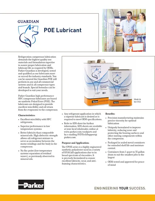
Refrigeration compressor lubrication demands the highest quality raw materials and formulation expertiseto assure proper lubrication and lubricant life as required by OEMs. Parker Guardian is developed, tested and qualified as our lubricants meet or exceed the industry standards. You can be assured the Guardian POE will perform in any and all commercial systems and in all compressor types and brands. Special formulas can be developed to suit your needs.Parker Guardian high performance HFC compressor lubricants are based on synthetic Polyol Ester (POE). The lubricants are designed to provide excellent miscibility and oil return from the evaporator to the compressor.Characteristics:• Excellent miscibility with HFC refrigerants.• Superior performance in low temperature systems• Better lubricity than comparable mineral oils. High dielectric strength allows oil/refrigerant mixture to serve as an insulator between the motor windings and the body in the compressor.• No floc point (low temperature systems separation of residual waxes), as previously observed in mineral oils.• Any refrigerant application in whicha superior lubricant is desired or isrequired to meet OEM specifications.• Refer to SDS sheet for furtherinformation. SDS sheets are availableat your local wholesaler, online at/coolparts andby e-mailing SVDTechSupport@.Purpose and Application:The VPOE series is a highly engineeredsynthetic polyolester used in a varietyof HVAC&R applications due to itsbroad spectrum of viscosities. Itis precisely formulated to ensureexcellent lubricity, wear, and anti-foaming characteristics.Benefits:• Precision manufacturing maintainsprecise viscosity for optimallubrication• Uniquely formulated to improvelubricity, reducing wear andprotecting the bearing surfaces andother moving components withinthe compressor.• Packaged in sealed metal containersfor extended shelf life and moisturecontrol.• Containers from 1 quart to 55 gallondrum to suit the smallest jobs to thelargest• OEM tested and approved for peaceof mindMade in the USAForm P-497 / 92016© 2016 Parker Hannifin CorporationParker Hannifin CorporationA/C & Refrigeration Aftermarket206 Lange Drive • Washington, MO 63090 USA phone 636 239 1111 • fax 636 239 /coolparts⚠WARNING – USER RESPONSIBILITYFailure or improper selection or improper use of the products described herein or related items can cause death, personal injury and property damage.This document and other information from Parker Hannifin Corporation, its subsidiaries and authorized distributors provide product or system options for further investigation by users having technical expertise.The user, through its own analysis and testing, is solely responsible for making the final selection of the system and components and assuring that all performance, endurance, maintenance, safety and warning requirements of the application are met. The user must analyze all aspects of the application, follow applicable industry standards, and follow the information concerning the product in the current product catalog and in any other materials provided from Parker or its subsidiaries or authorized distributors.To the extent that Parker or its subsidiaries or authorized distributors provide component or system options based upon data or specifications provided by the user, the user is responsible for determining that such data and specifications are suitable and sufficient for all applications and reasonably foreseeable uses of the components or systems.NON-WARRANTY – All data, statements and recommendations contained herein are based upon the best information available and are believed to be reliable. However, no warranty, either expressed or implied, is made concerning the application of this product since the customer’s use cannot be controlled. Statements concerning the use of this product should not be construed as suggestions, recommendations or inducements that it be used in violation of patent rights or in violation of any applicable laws or regulations. Product improvement is a continuous process at Virginia, therefore, product specifications may change without notice.The table below provides a guide for Residential Air Conditioning as well as Industrial and Commercial Refrigeration andAir Conditioning.POE LubricantComplementary products Parker ETK Acid Test Kit or the Sporlan TA-1 Acid Test Kit are suitable for use with the Parker Guardian Series. For more detailed analysis use the OA-1 Test Kit which provides complete analysis in 48 hours with recom-mendations for correcting out of specification parameters.。

e = ElectronicNotification (e-mail withfull datas)TN+OR = Transmittal &OriginalDiscipline DescribeGeneral All RecipientGeneral General design DataQA PRE-QUALIFICATION DOCUMENT HUAWEI NDT (BOMESC NDT SERVICES SUBCONTRACTORSA Material Requisition for Kitchen Fire Suppression System - Living Quarter Platform PP Materials Management SystemST Clarification for the abrasive of surface preparationQA BOMESC WELDING PACKAGE NO. 2 FOR STRUCTUREQA BOMESC WELDING PACKAGE NO. 3 FORSTRUCTUREQA BOMESC WELDING PACKAGE NO. 4 FOR STRUCTUREQA BOMESC WELDING PACKAGE NO. 5 FOR STRUCTUREQA BOMESC WELDING PACKAGE NO. 6 FOR STRUCTUREQA BOMESC WELDING PACKAGE NO. 7 FOR STRUCTUREQA BOMESC WELDING PACKAGE NO. 8 FOR STRUCTUREQA BOMESC WELDING PACKAGE NO.11 FOR STRUCTUREQABOMESC WELDING PACKAGE NO.12 FOR STRUCTUREQA BOMESC WELDING PACKAGE NO. 13 FOR STRUCTUREQA BOMESC WELDING PACKAGE NO. 14 FOR STRUCTUREQA BOMESC WELDING PACKAGE NO. 15 FOR STRUCTUREQA BOMESC WELDING PROCEDURE SPECIFICATION FOR SKID SHOESQA BOMESC WELDING PACKAGE NO. 3A FOR STRUCTUREQA BOMESC WELDING PACKAGE NO. 4 FOR STRUCTUREPI Equipment Layout LQ First Deck Layout at TOS.EL.+16.50PI COMPUTER STRESS CALCULATION NOTE -CN-007PI COMPUTER STRESS CALCULATION NOTE -CN-002PI COMPUTER STRESS CALCULATION NOTE -CN-020PI Computer Stress Calculatation Note For Level-3 Lines - CN-005_LQPI Computer Stress Calculatation Note For Level-3 Lines - CN-006_LQPI Computer Stress Calculatation Note For Level-3 Lines - CN-021_LQe = ElectronicNotification (e-mail withfull datas)TN+OR = Transmittal &OriginalDiscipline Describee = ElectronicNotification (e-mail withfull datas)TN+OR = Transmittal &OriginalDiscipline Describee = ElectronicNotification (e-mail withfull datas)TN+OR = Transmittal &OriginalDiscipline Describee = ElectronicNotification (e-mail withfull datas)TN+OR = Transmittal &OriginalDiscipline Describee = ElectronicNotification (e-mail withfull datas)TN+OR = Transmittal &OriginalDiscipline Describee = ElectronicNotification (e-mail withfull datas)TN+OR = Transmittal &OriginalDiscipline Describee = ElectronicNotification (e-mail withfull datas)TN+OR = Transmittal &OriginalDiscipline Describee = ElectronicNotification (e-mail withfull datas)TN+OR = Transmittal &OriginalDiscipline Describee = ElectronicNotification (e-mail withfull datas)TN+OR = Transmittal &OriginalDiscipline Describee = ElectronicNotification (e-mail withfull datas)TN+OR = Transmittal &OriginalDiscipline Describee = ElectronicNotification (e-mail withfull datas)TN+OR = Transmittal &OriginalDiscipline Describe℃e = ElectronicNotification (e-mail withfull datas)TN+OR = Transmittal &OriginalDiscipline Describee = ElectronicNotification (e-mail withfull datas)TN+OR = Transmittal &OriginalDiscipline Describee = ElectronicNotification (e-mail withfull datas)TN+OR = Transmittal &OriginalDiscipline Describee = ElectronicNotification (e-mail withfull datas)TN+OR = Transmittal &OriginalDiscipline Describee = ElectronicNotification (e-mail withfull datas)TN+OR = Transmittal &OriginalDiscipline Describee = ElectronicNotification (e-mail withfull datas)TN+OR = Transmittal &OriginalDiscipline Describee = ElectronicNotification (e-mail withfull datas)TN+OR = Transmittal &OriginalDiscipline Describee = ElectronicNotification (e-mail withfull datas)TN+OR = Transmittal &OriginalDiscipline DescribeLEGEND:e = ElectronicNotification (e-mail withfull datas)TN+OR = Transmittal &OriginalDiscipline Describe。
欧洲变压器标准(EN Transformer standards)Measureme ntof tur ns ratio on atran sformer used ina couplerEN 50152-3-3-2001 铁路应用固定装置交流开关的特殊要求第3-3部分:专门用于交流牵引系统的测量、控制和保护装置单相Railway applicati ons -Fixedin stallati ons- Particularrequireme nts for a.c.switchgear -Part 3-3: Measurement, con trol and protection devices for specificuse in a.c. tracti onsystems- Sin gle-phasein ductive voltage transformersEN 50180-1997 充液变压器用1kV 至36kV和250A 至1.25kA的套管Bush ings above 1 kVup to 36 kV and from250 A to 3,15 kA forliquid filled transformersEN 50181-1997 不包括充液变压器在内的设备用1kV 至36kV和250A 至1.25kA的插入套管Plug-i n typebushi ngs above 1 kVup to 36 kV and from250 A to 1,25 kA forequipment other thanliquid filledtran sformersEN 50216-1-2002 电源变压器及电抗器配件第1 部分:总则Power tran sformer andreactor fittings -Part 1:GeneralEN 50216-2-2002 电源变压器及电抗器配件第2 部分:带保油箱的充液式变压器和电抗器的气动Power tran sformer andreactor fittings -Part 2:Gas and oil actuatedrelay for liquidimmersedEN 50243-2002 充液变压器24kV和36kV 以及5kA和8kV的室外套管Outdoor bushings for24 kV and 36 kV andfor 5 kA and 8 kA, forliquid filled transformersEN 50299-2002 最咼电压为72.5kV 至550KV设备的变压器和电抗器用油浸电缆连接组件Oil-immersed cableconn ecti on assembliesfor tran sformers andreactors hav ing highestvoltage for equipme ntU<(l ndex)m> from 72,5kV to 550 kVEN 50329-2003 铁路应用牵引变压器Railway applicati ons -Fixed in stallati ons -Tracti ontran sformersEN 50336-2002 不大于36kV的变压器和电抗器电缆箱的套筒Bush ings for transformers and reactorcable boxes not exceeding 36 kVEN 50386-2002 注液变压器用1kV及以下和250 A 至5 kA的套管Bush ings up to 1 kVand from 250 A to 5 kA,for liquid filled transformersEN 50387-2002 注液变压器用1kV及以下和1.25 kA 至5 kA的母线套管Busbar bush ings up to1 kV and from 1,25 kAto 5 kA, for liquid filledtran sformersEN 60044-3-2003 仪器变压器第3部分:组合式变压器In strume nt transformers - Part 3:Combi ned transformers (IEC 60044-3:2002) / Note: Endorseme nt n oticeEN 60044-8-2002 仪器变压器第8部分:电流变压器In strume nttran sformers - Part8: Electro nic curre nttran sformers (IEC60044-8:2002) / Note:En dorseme nt n oticeEN60076-1-1997+A1-2000+A12-2002 电力变压器第1部分:总则Power tran sformers -Part 1: General (IEC60076-1:1993,modified)EN 60076-10-2001 电力变压器第10部分:声级的测定Power tran sformers -Part 10:Determ ination of soundlevels (IEC 60076-10:2001)EN 60076-2-1997 电力变压器第2部分:温升Power tran sformers -Part 2: Temperaturerise (IEC 60076-2:1993,modified)EN 60076-3-2001 电力变压器第3部分:绝缘水平、电介质试验和空气中的外间隙Power tran sformers -Part 3: In sulati onlevels, dielectric testsand exter nal clearances in air (IEC 60076-3:2000 + Corrigendum2000)EN 60076-4-2002 电力变压器第4部分:闪电脉冲和开关脉冲试验指南电力变压器和电抗器Power tran sformers -Part 4: Guide to thelight ning impulse andswitch ing impulse testing;Power tran sformersand reactors (IEC60076-4:2002) /Note: En dorseme nt noticeEN 60076-5-2000 电力变压器第5部分:承受短路的能力(IEC60076-5:2000 )Power tran sformers -Part 5: Ability to withstand short circuit (IEC60076-5:2000)EN 60146-1-3-1993 半导体变换器第1-3部分:变压器和电抗器Semic on ductor convertors- Gen eralrequireme nts and linecommutated convertors- Part 1-3: Transformers and reactors(IEC 60146-1-3:1991)EN 60310-1996 铁路应用运输车辆的牵引变压器和电感器Railwayapplicati ons -Tracti ontran sformers and inductors on rolli ng stock(IEC 60310:1991,modified)EN 60417-1/prAAA-2002 用于5945型小型变压器的图形符号:变压器绝缘、短路试验修改草案AAAIEC 60417: Graphicalsymbol for use on smalltran sformers 5945 Pr:Isolat ing tran sformer,short-circuit proofEN 60417-1/prAAAC-2002 用于5947型小型变压器的图形符号:变压器绝缘安全、短路试验修改草案AAACIEC 60417: Graphicalsymbol for use on smalltran sformers 5947 Pr:Safety isolati ng transformer, short-circuitproofEN 60417-1/prAAAD-2002 用于小型变压器5948型的图形符号:变压器绝缘微扰衰减法、总则修改草案AAADIEC 60417: Graphicalsymbol for use on smalltran sformers 5948 Pr:Perturbati on atte nuatio n压器绝缘总则图形符号修改草案AAU small tran sformers 5221/02: Isolat ing tran sformer, gen eralEN 60417-1/prAAV-2002 用于小型变压器5222/02 型变压器绝缘总则图形符号修改草案AAVIEC 60417: Graphicalsymbol for use on smalltran sformers 5222/02:Isolat ing tran sformer,gen eralEN 60417-1/prAAW-2002 用于小型变压器5941型自动转换器总则图形符号修改草案AAWIEC 60417: Graphicalsymbol for use on smalltran sformers 5941 Pr:Auto-tra nsformer, generalEN 60417-1/prAAX-2002 用于小型变压器5942型自动转换器非短路试验图形符号修改草案AAXIEC 60417: Graphicalsymbol for use on smalltran sformers 5942 Pr:Auto-tra nsformer, non-short-circuit proofEN 60417-1/prAAY-2002 用于小型变压器5221/02 型自动转换器短路试验图形符号修改草案AAYIEC 60417: Graphicalsymbol for use on smalltran sformers 5943 Pr:Auto-tra nsformer,short-circuit proofEN 60417-1/prAAZ-2002 用于小型变压器5944型变压器绝缘非短路试验图形符号修改草案AAZIEC 60417: Graphicalsymbol for use on smalltran sformers 5944 Pr:Isolat ing tran sformer,non-short-circuit proofEN 60598-2-6-1994+A1-1997 灯具第2分:特殊要求第6:内装变压器的Luminaires - Part 2:Particular requireme nts-感器的叠片铁心包第2部分:用YEE2叠片铁芯的电性能tran sformers and in ductors for use in telecom mun icatio n and electr onic equipme nt - Part 2: Electrical characteristics for cores using YEE 2 lam in ati ons (IEC 61021-2:1995)EN 61050-1992+A1-1995 空载输出电压超过1000V的管形放电用变压器规范(一般叫做氖管变压器)一般要求和安全要求Tran sformers fortubular discharge lampshav ing a no-loadoutput voltage exceeding 1000 V (ge nerallycalled neon-transformers); gen eraland safety requirements (IEC 61050:1991 +corrige ndum 1992,modified)EN 61203-1994 电工用合成有机酯设备中变压器酯类的维护指南Syn thetic orga nicesters for electricalpurposes -Guide formaintenance of transformer esters inequipme nt (IEC61203:1992)EN 61248-1-1997 电子和电信设备用变压器和电感器第1部分:通用规范Tran sformers and inductors for use inelectro nic and telecommun icatio n equipme nt- Part 1: Gen ericspecificati on (IEC61248-1:1996)EN 61248-2-1997 电子和电信设备用变压器和电感Tran sformers and inductors for use in器第2部分:采用能力批准程序的信号变压器分规范electro nic and telecom mun icatio n equipme nt - Part 2: Sect ional specification for signal transformers on the basis of the capability approval procedure (IEC 61248-2:1996)EN 61248-3-1997 电子和电信设备用变压器和电感器第3部分:采用能力批准程序的电源变压器分规范Tran sformers and inductors for use inelectro nic and telecommun icatio n equipme nt- Part 3: Sect ionalspecification for powertran sformers on thebasis of the capabilityapproval procedure(IEC 61248-3:1996)EN 61248-4-1997 电子和电信设备用变压器和电感器第4部分:采用能力批准程序的转换供电方式(SMPS的开关电源变压器分规范Tran sformers and inductors for use inelectro nic and telecommun icatio n equipme nt- Part 4: Sect ionalspecification for powertran sformers forswitched mode powersupplies (SMPS) on thebasis of the capabilityapproval procedure(IEC 61248-4:1996)EN 61248-5-1997 电子和电信设备用变压器和电感器第5部分:采用能力批准程序的脉冲变压器Tran sformers and inductors for use inelectro nic and telecommun icatio n equipme nt- Part 5:分规范Sect ional specificationfor pulse tran sformerson the basis of thecapability approvalprocedure (IEC 61248-5:1996)EN 61248-6-1997 电子和电信设备用变压器和电感器第6部分:采用能力批准程序的电感器分规范Tran sformers and inductors for use inelectro nic and telecommun icatio n equipme nt- Part 6: Sect ionalspecification for inductors on the basis ofthe capability approvalprocedure (IEC 61248-6:1996)EN 61248-7-1997 电子和电信设备用变压器和电感器第7部分:采用能力批准程序的高频电感器和中频变压器分规范Tran sformers and inductors for use inelectro nic and telecommun icatio n equipme nt- Part 7: Sect ionalspecification for high-freque ncy in ductorsand in termediatefreque ncy transformerson the basis of thecapability approvalprocedure (IEC 61248-7:1997)EN 61378-1-1998 交流器变压器第1部分:工业用变流变压器Conv ertortran sformers - Part 1:Tran sformers for industrial applicati ons(IEC 61378-1-1997)cable boxes on the high-voltage an d/or low-voltage side - Sectio n 3: Cable boxesHD 428.3 S1-1994 50 Hz、50 至2500 kVA、设备最咼电压不超过36 kV的三相油浸式配电变压器第3部分:设备最咼电压等于36 kVThree phase oil-immersed distributio ntran sformers 50 Hz,from 50 to 2500 kVAwith highest voltage forequipme nt not exceeding 36 kV- Part 3:Suppleme ntaryrequireme nts for transformers with highestvoltage for equipme ntequal to 36 kVHD 428.4 S1-1994 50 Hz、50 至2500 kVA、设备最咼电压不超过36 kV的三相油浸式配电变压器第4部分:负载非正弦电流变压器Three phase oil-immersed distributio ntran sformers 50 Hz,from 50 to 2500 kVAwith highest voltage forequipme nt not exceeding 36 kV- Part 4:Determ ination of thepower rati ng of a transformer loaded withnon-sinu soidal currentsHD 428.6 S1-2002 50 Hz、50 至2500 kVA、设备最咼电压不超过36 kV的三相油浸式配电变压器第6部分:关于加压波纹外壳的Three phase oil-immersed distributio ntran sformers 50 Hz,from 50 kVA to 2500kVA with highestvoltage for的最高电压Um大于1kV的设备用的电源变压器和电抗器的使用和特殊设计特点for particular desig n features for power tran sformers and reactors with highest voltage for equipme nt Um exceedi ng 1 kV, perma nen tly in corporated in build ingsprEN 60076-11-2002 电力变压器第11部分:干式变压器IEC 60076-11: Powertran sformers - Part 11:Dry-type tran sformersprEN 60076-8-1997 电力变压器第8部分:应用指南IEC 60076-8: Powertran sformers - Application guideprEN 60296-2003 变压器和开关设备用未使用过的矿物绝缘油规范IEC 60296, Ed. 3:Fluids for electrotech nical applicati ons - Unused min eral in sulati ngoils for tran sformersand switchgearprEN 60310-2003 铁路应用运输车辆的牵引变压器和电感器Railway applicati ons -Tracti on tran sformersand in ductors on boardrolli ng stockprEN 60989-1994 单独变压器自藕变压器、可变频率变压器和电抗器Separati ng transformers, autotransformers, variable transformers and reactors(IEC 60989:1991,modified)prEN 62041-2003 电源变压器、供电部件和类似部件电磁兼容要求IEC 62041, Ed. 1:Power tran sformers,power supply un its,reactors and similarproducts - EMCrequireme nts编号中文名称英文名称。
July 2019W S H P -P R C 025F -E NHose Kit AccessoriesAutomatic and ManualBalancingIntroductionChoosing the best flow control balancing device for water-source heat pump equipment just got easier.Superior circuit balancing of the HVAC equipment is an important aspect to the overall layoutand design of the HVAC system.Proper balance of the system can protect the HVAC equipment,while providing a longer equipment life.Superior circuit balancing can save energy by supplyingthe proper amount of fluid to make your system perform at its highest efficiency.Trane®’s flow balancing choices have taken the guess work out of system balancing.From themost economical means of system balancing,to an automated flow system,Trane®’s flow kitssupport a variety of water-source heat pump applications.The three hose kit choices used in HVAC systems today include:•Ball valve hose kit with PT ported ball valves•Manual hose kit with a manual balancing valve•Automatic,self-balancing flow hose kitWith flow velocities ranging from0.5to60.0gpm,our automatic balancing device supports avariety of water-source heat pump applications and equipment sizes.It is typically the idealchoice in system balancing,but up-front expense associated to auto flow balancing often detersowners into a manual balancing system.With automatic flow balancing,the actual money spent on the automatic flow kits,can be quicklymade up when the tedious work of balancing,and re-balancing the system is recouped by theinstalling contractor.And in the event that a new piece of equipment is added to the system,orequipment servicing is required,re-balancing of the entire system is necessary.Overall accuracy in the balancing of water flow to the equipment may also be in question whenusing the manual balancing method.Especially in applications where varying coolingrequirements may offer a substantial energy savings to the owner.In this application,manualbalancing to support varying pump speeds is not practical.Automatic flow kits are an excellent choice in providing protection through a constant,accurateflow to the equipment.Regardless of your balancing choice and need,Trane®suggests several alternatives.All hosekits are model number configured to better support a range of decisions made in any givenapplication.Quality components are an important aspect to installing a fail-proof system.Our hose kits arefully assembled and tested at the manufacturing site to help ensure leaks are non-existent.Allflow kits are outfitted with a braided,stainless steel hose on both the supply and the return sideof the system.The available hose length options are18-,24-,and36-inches.Optional components,such as a Y-ball strainer,sustain systems using brackish or hard water.A2-position isolation valve may be specified in the hose kit design for systems supplying variablewater volume control.For questions in entire system balancing for overall life cycle savings,Trane®has the answer. CopyrightThis document and the information in it are the property of Trane,and may not be used orreproduced in whole or in part without written permission.Trane reserves the right to revise thispublication at any time,and to make changes to its content without obligation to notify anyperson of such revision or change.TrademarksAll trademarks referenced in this document are the trademarks of their respective owners.I n t r o d u c t i o n Revision History•Updated product images.•Updated working pressure value to maximum for hose kit specification.Table of ContentsModel Number Description (5)Features and Benefits (7)Ball Valve Flow Control (7)Manual Balancing Flow Control (8)Automatic Balancing Valve (9)Self-Balancing Hose Kits (13)Model Number DescriptionDigit1—Hose Kit Type4=Automatic inline hose kit6=Automatic Y-body hose kit3=Automatic inline hose kit with zone valve 5=Automatic Y-body hose kit with zone valve7=Ball valve or manual hose kit with zone valve8=Ball valve or manual hose kitDigit2—Hose Kit Diameter0=½”Diameter hose1=¾”Diameter hose2=1”Diameter hose3=1¼”Diameter hose4=1½”Diameter hose5=2”Diameter hoseDigit3—Hose Length1=18”Stainless steel hose2=24”Stainless steel hose3=36”Stainless steel hoseDigit4—Strainer Option0=No strainer3=Strainer with blow-down valve and hose connectorDigit5—Supply Ball Valve4=Supply ball valve with pressure temperature portDigit6—Return Ball Valve1=Return ball valve(no options)4=Return ball valve with pressure temperature portDigit7–10—Flow ControlNote:If0.00Manual Controls is selected for digits7-10,the Cv ratings will need tobe selected for digits14-15.IfAutomatic Balancing is required,theflow rate(gpm)must be selected fordigits for digits7-10,and00must beselected for digits14-15.A.AA=Ball valve hose Kit0.00=Manual balancing valve flow control 0.50=0.5gpm0.63=0.63gpm0.75=0.75gpm1.00=1.00gpm1.13=1.13gpm1.25=1.25gpm1.50=1.50gpm1.63=1.63gpm1.75=1.75gpm2.00=2.00gpm Digit7–10—Flow Control(continued)2.25=2.25gpm2.50=2.50gpm3.00=3.00gpm3.25=3.25gpm3.50=3.50gpm4.00=4.00gpm4.50=4.50gpm5.00=5.00gpm5.50=5.50gpm6.00=6.50gpm7.00=7.00gpm7.50=7.50gpm8.00=8.00gpm9.00=9.00gpm10.0=10.0gpm11.0=11.0gpm12.0=12.0gpm13.0=13.0gpm14.0=14.0gpm15.0=15.0gpm16.0=16.0gpm18.0=18.0gpm20.0=20.0gpm22.0=22.0gpm25.0=25.0gpm26.0=26.0gpm27.0=27.0gpm28.0=28.0gpm29.0=29.0gpm31.0=31.0gpm32.0=32.0gpm33.0=33.0gpm34.0=34.0gpm35.0=35.0gpm36.0=36.0gpm37.0=37.0gpm38.0=38.0gpm39.0=39.0gpm40.0=40.0gpm41.0=41.0gpm42.0=42.0gpm43.0=43.0gpm44.0=44.0gpm45.0=45.0gpm46.0=46.0GPM47.0=47.0gpm48.0=48.0gpm49.0=49.0gpm50.0=50.0gpm51.0=51.0gpm52.0=52.0gpm53.0=53.0gpm54.0=54.0gpm55.0=55.0gpm56.0=56.0gpm57.0=57.0gpm58.0=58.0gpm59.0=59.0gpm60.0=60.0gpmDigit11—Memory Stop Option0=No memory stop7=Memory stop(for ball valve hose kit)8=Memory stop(for manual balancingvalve)Digit12—Reducer Option0=No reducerR=Reducer to decrease one sizeDigit13—Isolation Valve0=No zone valveR=Zone valveDigit14-15—Manual Flow Control00=***AA=0.23Cv(½”hose)BA=0.46Cv(½”hose)CA=0.55Cv(½”hose)DA=0.87Cv(½”hose)EA=1.1Cv(¾”hose)FA=1.8Cv(½”hose)GA=2.2Cv(¾”hose)HA=2.3Cv(1”hose)JA=3.3Cv(½”hose)KA=4.0Cv(¾”hose)LA=5.4Cv(½”hose)MA=5.4Cv(1”hose)NA=5.5Cv(1¼”hose)PA=6.7Cv(¾”hose)RA=9.2Cv(1”hose)SA=9.8Cv(1¼”hose)TA=13Cv(2”hose)UA=14Cv(1½”hose)VA=19Cv(1½”hose)WA=20Cv(1”hose)XA=20Cv(1¼”hose)YA=24Cv(1¼”hose)ZA=34Cv(2”hose)ZD=44Cv(1½"hose)ZP=56Cv(2”hose)Mesurflo In-line Automatic Balancing ValveStep-Down ReducerStainless Steel Supply/Return HosesY-Body Valve 1/2” to 1 1/4” Dia.Ball Valvewith P/T PortReturn Ball Valve No P/T PortMesurflo In-line AutomaticBalancing Valve 1/2” to 1 1/4” Dia.Standard Valve 1-1/2” to 2” Dia.1-1/2" to 2" Dia. YBall Strainer with Blow Down Valve and Hose Connector1/2” to 1” Zone Valve1-1/4” to 2-1/2”Zone Valve1/2" to 1-1/4" Dia.YBall Strainerwith Blow Down Valve and Hose ConnectorM o d e l N u m b e r D e s c r i p t i o nFeatures and BenefitsBall Valve Flow ControlTraditionally,the first choice in a balancing device on a water-source heat pump application isthe lowest first cost option.In water-source heat pump fluid flow balancing,this typicallyemploys a manual balancing(ball valve)device with hoses.This method utilizes pressure/temperature(P/T)measurement ports on the ball valves at the entering and leaving side of theheat pump so that pressures and temperatures can be measured within the water piping.A ballvalve is then manually throttled to change the amount of flow to the unit to reach the desiredtemperature or pressure differential.A d v a n t a g e s•Low first cost•Direct access to the water-loop through P/T port for future trouble shooting•Temperature and pressure measurements can cross check balancing•Better water temperature measurement than external sensorsD i s a d v a n t a g e s•Flow accuracy of±25%•Each unit must be balanced multiple times because of changing system conditions inbalancing other units•Integral differential temperature balancing is less accurate than differential pressurebalancing•Pressure drop of hose and fittings must be accounted for in differential pressuremeasurementsFigure1.Ball valve hose kitReturnBall ValveSupplyOptional Y-Ball Strainer W/ Blowdown Valve & HoseConnector Optional 2-Position Zone ValveB a l l v a l v e f l o w c o n t r o l h o s e k i t i s e q u i p p e d w i t h:(2)Stainless steel braided hoses with brass end fittings containing fiber washers.(2)Brass ball valves with brass ball with optional P/T port on return side.(1)Optional electronic zone valve for variable water volume control.(1)Optional Y-ball strainer with brass cap and stainless steel mesh screen (includes blow down valve and hose connector).Table 1.Ball valve Cv factorsTable 2.Strainer Cv factorsN o t e :Pressure drop information can be derived from the formula below:DP =Q 2SpQ =flow in gpmSp =specific gravity DP =pressure drop in psiCv =flow coefficientCv 2Manual Balancing Flow ControlAnother choice in manual fluid flow balancing of a water-source heat pump includes a Hays ™manual balancing valve circuit setter flow control option.This manual balancing method uses an in-line flow measurement device and an adjustment feature to measure and set flow rates at each heat pump.A d v a n t a g e s •In-line flow measurement device•Easier to use than traditional or differential pressure/differential temperature methods D i s a d v a n t a g e s•Flow accuracy of ±20%•Higher pressure drop of circuit setters result in additional pumping energy costs (a ¾”circuit setter with 8-gpm flowing has 15-feet of pressure drop)•Direct readout of flow rate is not possible with a manual balancing valve•Each unit must be balanced multiple times because of changing system conditions in balancing other equipmentM a n u a l f l o w c o n t r o l h o s e k i t i s e q u i p p e d w i t h :(2)Stainless steel braided hoses with brass end fittings containing fiber washers.(1)Brass ball valve (supply)with optional P/T port.(1)Brass manual valve (return)includes memory stop positive shut-off and dual P/T ports.(1)Optional electronic zone valve for variable water volume control.(1)Optional Y-ball strainer with brass cap and stainless steel mesh screen (includes blow down valve and hose connector).F e a t u r e s a n d B e n e f i t sFigure 2.Manual balancing valve hose kitReturnBall ValveManual w/PT’sSupplyOptional Y-Ball Strainer w/Blowdown Valve & HoseConnectorOptional 2-PositionZone ValveAutomatic Balancing ValveFor the latest Hays ™Fluid Controls specification,please reference the following site:/category/automatic-balancing-valvesFor automatic balancing of a water-source heat pump,the Hays Fluid Controls automatic hose kit provides a constant flow rate over the pressure differential range of differential operating pressure:2-80psid 0.50-5.00gpm,3-80psid 5.50-9.00gpmAt low differential pressure,the flow area required to achieve higher flow can exceed the flow area available for the respective series.Therefore,the minimum pressure differential requirement is increased for the higher flow ranges of each series Mesurflo ®valve.As system pressures change (through further addition of heat pumps,for example)each individual flow control valve will automatically adjust to the new system conditions.F e a t u r e s a n d B e n e f i t sIn variable water volume applications,there can be large variations in the system water pressure.These pressure changes can adversely affect the system balance and heat pump operation.A self balancing hose kit can provide continuous balancing in this application because of its ability to automatically adjust to the varying system conditions.A d v a n t a g e s •Flow accuracy of ±10%•Broader application in variable water volume pumping systems•Greater flow accuracy results in operation closest to design,with least tenant complaints •Only one pressure differential range of 2to 80psid 1•Labor savings during balancing can offset increased material cost•Same or less cost as manual balancing hose kits on smaller diameter hose kits D i s a d v a n t a g e s•Greater first cost over other manual balancing methodsA u t o m a t i c b a l a n c i n g v a l v e h o s e k i t i s e q u i p p e d w i t h :•Stainless steel braided hoses with brass end fittings containing fiber washers •Brass manual shut-off valves with P/T port on supply side •Brass self-balancing valve•Optional electronic zone valve for variable water volume control•Optional brass Y-ball strainer with brass cap and stainless steel mesh screen (includes a blow down valve and hose connector).Figure 3.Automatic balancing valve hose kitBall ValveSupplyOptional Y-Ball Strainer w/Blowdown Valve & HoseConnectorAutomatic Balancingvalve w/PT’sOptional 2-PositionZone ValveReturnTable 3.Hose kit selection vs.heat pump tonnageF e a t u r e s a n d B e n e f i t s1.At low differential pressure the flow area required to achieve higher flow can exceed the flow area available for the respective series.Therefore,the minimum pressure differential requirement is increased for the higher flow ranges of each series Mesureflo ®valve.F e a t u r e s a n d B e n e f i t s Table3.Hose kit selection vs.heat pump tonnage(continued)Note:Consult heat pump manufacturer for other temperature applications.Table4.Kit w/ATC,1ball valve,Y-ball strainer&Mesurflo®automatic balancing valve,24”hoseF e a t u r e s a n d B e n e f i t sTable4.Kit w/ATC,1ball valve,Y-ball strainer&Mesurflo®automatic balancing valve,24”hose(continued)Table5.Kit,1ball valve,Y-ball strainer&Mesurflo®automatic balancing valve,24”hoseSelf-Balancing Hose KitsThe Mesurflo®automatic balancing valve contains a rubber diaphragm that is designed to flexinto a contoured orifice plate.This allows the valve to decrease the water flow path as pressureincreases.The pressure differential ranges of a Mesurflo®automatic balancing valve covers2to80psid2.The flexing of the rubber diaphragm against the fixed orifice plate makes the Mesurflo®valve difficult to clog and resistant to cavitation damage.Outside of the pressure differentialwindow,the controller continues to perform as high as150psid,but does not become a fixedorifice.N o t e:The automatic balancing valve is a constant flow rate device that contains a variable orifice to govern water flow.Since it is a variable orifice,it can not be described with a Cv or apressure drop at a given flow for piping system design purposes.Conversely,the designermay assume a constant flow rate over the pressure differential range of2–5to80psid asone uses constant pressure in systemdesign.PSID = 15Diaphragm beginningto flex into contouredorifice platePSID = 0Diaphragm inoriginal shapePSID = 80Diaphragm fullyflexed intocontoured orificeplateThere are three features that every self-balancing valve should possess to accomplish the job ofautomatically balancing an HVAC system in the industry.The valve should be:•Non Clogging•Quiet•AccurateNon CloggingThe live flexing action of the elastomeric diaphragm against the orifice seat permits passage ofreasonably sized particles of sludge,rust balls,thread chips,and other debris.Because theworking parts are of a two piece design,they are resistant to fouling.Back pressure forces thediaphragm away from the orifice seat allowing any debris to be back-flushed away.Mesurflo®isthe only balancing valve that provides unrestricted flow during back flush.QuietBy design,the Mesurflo®automatic balancing valve is inherently quiet.The only moving part isan elastomeric polymer diaphragm in an orifice seat that is made from polyphenylsulfone.Together,these materials have a natural sound deadening ability.The Mesurflo®valve neitherclicks nor is noisy,and has only one control range.AccurateWhat does accurate mean?Is it the stable,predictable delivery of thermal energy in a hydronicsystem?The Mesurflo®valve is accurate±10%,that equates to99.8%heat transfer.Because thepolymer diaphragm compensates for changes in fluid temperature the valve provides stablethermal system performance.The addition of antifreeze to the fluid further increases the need forthe offsetting characteristics of the Mesurflo®automatic valve.F e a t u r e s a n d B e n e f i t sF e a t u r e s a n d B e n e f i t sHose Kit SpecificationsBall Valve Flow ControlEach kit contains two ball valves,two flexible hoses,and may include a high flow Y-ball strainerand various other accessories.Manual BalancingEach kit contains two manual ball valves,one Hays™Mesurmeter(with Venturi Cv insert),twoflexible hoses,and may include a high flow Y-strainer and various other accessories.The manual balancing valve body and ball valve are constructed from brass.It contains amaximum working pressure of400psi with a maximum flow temperature of32–225°F(operatingtemperature range)and a minimum flow temperature of15°F(-10°C).Automatic Balancing ControlEach kit contains a Hays Fluid Controls automatic balancing valve,two ball valves,two flexiblehoses,a high flow Y-ball strainer,and includes a blow-down and various other accessories.The automatic balancing valve is factory set to a rated flow,and shall automatically control theflow to within10%of the rated value over a40to1differential pressure,operating range(2-80psid0.50-5.00gpm,3-80psid5.50-9.00gpm3).Operational temperature is rated32–225°F.Thevalve body is constructed from hot forged brass UNS C37700per ASTM B-283latest revision.The ball valve is constructed from forged brass with either a chromed brass ball or316stainlesssteel ball valve construction.It is rated from fluid32–225°F.Valve bodies are suitable for400psig,with a working pressure rating per ASTM A53B threaded joint type.A pressure/temperature testport is provided for verifying the pressure differential and system temperature.All supply and return hoses are equipped with swivel end connections.All end connections arepermanently crimped to meet state pressure ratings.½”to1¼”hose material is EPDM rubber.Hose material is stainless steel braid over an EPDM liner,and bonded to the braid.Hoses arerated for32-225°F.½”to1¼”hose connectors are permanently crimped.Swivels shall be BP with a male NPT.Adapters are fixed male NPT.All connections are brass and have reusable thread sealant pre-applied to the tapered pipe threads.1½”and larger hose materials are a single stainless steel braid over a corrugated type321stainless steel tube,butt welded to carbon steel end fittings with either individual or integratedbrass unions.Operational temperature are rated from25°F-225°F.Hoses are rated for a maximum working pressure of400psi.Minimum burst pressure is fourtimes the working pressure.The Y-ball strainer body is constructed of brass with a brass cap.The cap is sealed with a nonasbestos gasket.The strainer body is suitable for400psig,with a maximum pressure rating of400.The strainer screen is304stainless steel with20-mesh.The strainer is ported with femalepipe thread per ASME/ANSI b1.20.1,and B31.9.The2position(on/off),24V,normally closed,spring return motorized zone valve is installed onthe return side of the system.The valve will open when the unit compressor begins running toallow water flow through the unit.As the compressor shuts down,the valve will slowly close offwater through the unit to reduce water consumption.N o t e sIngersoll Rand(NYSE:IR)advances the quality of life by creating comfortable,sustainable and efficient environments.Our people and our family of brands—including Club Car®,Ingersoll Rand®,Thermo King®and Trane®—work together to enhance the quality and comfort of air in homes and buildings;transport and protect food and perishables;and increase industrial productivity and efficiency.We are a global business committed to a world of sustainable progress and enduring results.Ingersoll Rand has a policy of continuous product and product data improvements and reserves the right to change design and specifications without notice.We are committed to using environmentally conscious print practices.。
n o管道元件库与设计的关系Design 通过等级指针指向管道元件Goto Spref Goto CatrefGoto Spref Goto Catref F or SDMParagon 的用途(What Paragon Does)Paragon 模块用于建立管道元件库和钢结构元件库,在可视化环境中可以定义各种复杂的元件,特殊元件的建立不需要编程创建等级包括管道等级管嘴等级电缆桥架等级和钢结 创建等级,包括管道等级,管嘴等级,电缆桥架等级和钢结构等级等所有的PDMS 等级n l yr o nF o创建壁厚表(NOMTAB)Create>Spec Table>Size Range Table…–添加等级所需管径并指定对应壁厚F or SDM o n l y创建分支表(BRTAB)Create>Spec Table>Branch Table…–控制添加到等级中的三通元件三通连接形式短代码创建异径表(BRTAB)Create>Spec Table>Reducer Table…–控制添加到等级中的大小头元件三通连接形式短代码F or SDM Uo n l y%PDMSDFLTS%\cat-pipetablecodes.pmldat 包含有默–管道壁厚SCH –三通连接形式缩写–大小头类型缩写Uo n l y创建等级管理层Create>Specification>World…Create>Specification>Specification…F or SDM等级属性指定等级类型为Piping设置等级参考设置材料、介质、螺栓及等级表参考F or SDM Uo n l y添加Heading编辑HeadingHeading 模板通过元件的类型挑选合适的HeadingF or SDM Uo n l y往等级中添加元件选择添加方式–Part Family…通过Part 添加元件–CE在Paragon Explorer 中选择CATE 添加–Search…通过关键字查找添加F or Uo n l y–阀门需要区分几种形式,阀门的GTYPE 是都是VALV ,SType 可以用GATE ,BALL ,CV 等来区分–一般使用SType 设置缺省项–考虑二三维校验,Stype 不宜超过四位Uo n l y使用管径表添加元件根据管径表确定添加元件尺寸范围使用异径表添加元件通过异径表控制大小头形式–Heading Type :REDUF or SDM Uo n l y编辑Answers修改等级元件属性F or SDM Uo n l yShop 属性自动按照等级中的编辑Reference修改等级元件参考F or SDMRemove to Limbo–将把等级元件(SPCO)移动到临时等级(LIMBOSPEC)中,等级中将不再可用,但不会影响已建立好的三维模型Delete Permanently–删除等级元件(SPCO),三维模型参考丢失Uo n l y–没有用户界面,使用命令行维护等级 进入Specon 模块–Modules>SpeconUo n l yn on o管嘴元件库生成150#,300# ANSI 法兰对应管嘴等级为例 管嘴元件库,生成方法同管道元件库Uo n l y生成管嘴等级生成管嘴等级,命名对应法兰标准–Create>Specification…对话框中的内容写到Spec 的下列属性中–Desc Ansi flange nozzle –Purp NOZZ150#法兰添加150#法兰类型–Gtype>AddF or SDM n l y加载元件–按Add 按钮,则Category 栏中选中的元件加入到Entries 栏中添加元件移除元件F or Uo n l y完成执行Build ,完成一个类型–Control>Build建立查看管嘴等级Display>Specifications…F or SDM Uo n l yn o保温元件库保温厚度元件库,参考/PDMSPIPE.CATA 中的示例Uo n l yr UonlyF o关联保温元件库Add New Items…编辑管径和温度保温等级中根据温度范围和管道范围直径设置保温厚度–Edit Answers…温度范围管径范围F or SDM Uo n l y–每个设计元件根据Branch的操作温度在保温等级中得到厚度roFn oHVAC 保温等级默认保温等级CADCHVACISPEC 保温等级的过滤条件–Purp of Spec = INSU –Purp of SPWL = HVACF or SDM o n保温等级内容HVAC 保温等级通过设计温度对应保温厚度特殊处理HVAC 保温的特殊处理–实际情况是HVAC 保温厚度与温度无关–保温厚度写入设计温度属性中F or SDM Uo n l yn o–Sdthickness创建特性库创建特性库管理层创建修改名称创建CMPTNew>CMPTF or SDM Uo n l y创建CMPDNew>CMPD–对应SCOM –重量重量设置等级特性参考设置等级元件中的Components Ref–元件特性与对应等级元件关联F or SDM Uo n l yylno。
补体C4测定试剂盒(免疫比浊法)
适用范围:本产品用于体外定量测定人血清中补体C4的含量。
1.1规格
具体产品规格见下表:
1.2组成成分
试剂1:
缓冲液50mmol/L
试剂2:
C4抗血清180ml/L
2.1 外观
2.1.1 外包装完整无破损;
2.1.2 试剂1:无色透明液体;
2.1.3 试剂2:无色或淡黄色澄清或微浊液体。
2.2 净含量
净含量不低于标示值。
2.3 试剂空白吸光度
在主波长340nm、副波长700nm、37℃条件下,试剂空白吸光度不大于0.3。
2.4 线性
2.4.1 线性范围
[5.0,80.0]mg/dl,相关系数r>0.990。
2.4.2 线性偏差
(30.0,80.0]mg/dl线性范围内,相对偏差不超过±15%;
[5.0,30.0]mg/dl线性范围内,绝对偏差不超过±4.5mg/dl。
2.5 分析灵敏度
检测浓度为38.5mg/dl的样本时,吸光度变化不小于0.08。
2.6 重复性
测试高、中、低浓度的血清样本或质控品,重复测试10次,CV≤10%。
2.7 批间差
用三个不同批号的试剂测试同一样本,重复测试3次,相对极差R≤10%。
2.8 准确度
测定ERM-DA470K/IFCC标准物质,测定结果应不超过标示值的±15%。
2.9 稳定性
原包装试剂2~8℃避光储存,有效期12个月。
效期后1个月内产品应符合2.3、2.4和2.8的要求。
B a s i c H V AC R e q u i r e m e n t暖通空调系统要求Basic Design Requirements基本设计要求1 General概述1.1 The HVAC Specification is applied for all the stores of China, which guide the design, procurement,construction & final acceptance works of the stores conversion,upgraded, retrofits or renovated and expansion. The sales area, shopping mall, office, storage, facilities plant, receiving yard, etc are involved.The detailed functions are as followings:本规范应用于中华人民共和国范围内家乐福的所有新建,改建的超级市场。
家乐福超市的功能分布包括卖场区,商铺区,仓库区,办公区及设备辅助用房。
1.1.1 In sales area the goods like the appliance, fabric, grocery, bakery, fish, meat, salar bar, vegetable, fruit,makeup, steamed & fried foods, etc are sold.其中卖场区包括化妆品,家电,服装,杂货食品,肉课,鱼课,沙拉吧,面包房,熟食,中式点心,蔬果等销售区域。
1.1.2 In shopping mall area the various of rent shops are occupied, such as the kinds of restaurants, food court,dress & shoes shop, laundry shop, bakery, beauty shop, tea shop, drugstore and so on.其中商铺区包括各种餐饮,食街,服装鞋类,洗衣店,面包蛋糕店,美容,茶类,药房等小型商铺。
1.1.3 The each department of the store occupies the office and executes the daily business. The storemanager office, finical office, security office, cashier office, maintenance office, conference room, locker room, negotiation room, smoke room & canteen, etc are usually necessary.办公区包括店长办公室,财务办公室,保安办公室,收银办公室,维修办公室,会议室,更衣室,谈判间等。
1.1.4 The storage is normally keeping the temporary goods for revolving; the goods are arranged by thedepartment. Normally there is the valuable and expansive goods storage inside.仓库区包括各类商品的临时普通仓库及精品贵重物品仓库,收货区及收货办公室等。
1.1.5 The receiving yard is connected to outside, transferred and the staff take over the goods at this area.收货区是和室外相通,收货人员在此接收货物。
1.1.6 The facility plant include the substation, power distribution plant, chillers & pumps plant, refrigerantequipments plant, AHU plant and so on, which are severed for the whole store.辅助设备房包括变配电间,区域配电间,冷冻机和泵房,制冷设备间,空调箱房等,其中的设备都服务于整个店。
1.2 Design Institute or Contractor shall complete the whole construction works with accordance to the latestversion of specifications, standards, regulations and code of practice which issued by national and regional government, and requirements by CARREFOUR which listed in the design contract and or tender and must co-ordinate with local codes and regulations.设计院或承包商都必须按照最新的国家和当地规范、标准和技术要求,以及CARREFOUR对每一项目的具体设计委托书或招标书要求完成整个建筑工程,并与当地的条例和法规相协调。
1.3 The HVAC system used for CARREFOUR area shall be operated and controlled independently out of thewhole building, which shall not to use with other tenements together. Meanwhile the energy counting shall be according to the water & electricity meter. Before the meters are gotten into use, the Precision Certification of the calibration & verification shall be submitted to the CARREFOUR for approval. If CARREFOUR has to use cooling & heating source system with other landlord’s tenements, and invest a lot for isolating the system, the thermal meter could be considered to use. The unit price by the thermal meter should be regulated in the lease contract.家乐福制冷和采暖空调系统必须独立于整个建筑,独立控制,同时其能源消耗的计量必须使用水表和电表准确的计量。
电表水表的投入使用之前,必须递交家乐福相关国家相关部门对此表具的精度审核计量校准报告。
如果不得不与其它租户共用一套冷热源系统,而且冷热源系统独立改造需要花费大量投资,可以考虑使用热表计量方式计费。
1.4 Every system listed in this booklet is the general descriptions of completed system of CARREFOUR, theremay be discrepancies among areas in China本标准中的各系统是对CARREFOUR完整系统的一般性描述,全国各地情况不同,具体可能会有所差别。
1.5 Design Principle and Standard设计依据ProposalArchitectural1.5.1 Approved批准的建筑设计方案1.5.2 CARREFOUR’ design data and requirements.由CARREFOUR提供的设计资料及要求1.5.3 Design data by relevant professional institutions相关专业提供的设计资料1.5.4 Relevant national specifications for HVAC, applicable items including but not limited to are listed asfollowings:暖通专业有关的国家规范,适用的规范条目包括但不限于如下:1.5.4.1 Specifications for Acceptance and Inspections for Construction Quality for HVAC《通风与空调工程施工质量验收规范》(GB50243-2002)1.5.4.2 Specification for Acceptance of Installation for Refrigeration and Air Separation Equipment《制冷设备、空气分离设备安装工程施工及验收规范》(GB50274-98)1.5.4.3 Specification for Acceptance of Installation for Air Compressor, Fan and Water Pumps《压缩机、风机、泵安装工程施工及验收规范》(GB50275-98)1.5.4.4 Standard Noise Level for Urban Environments《城市环境噪声标准》(GB3096-82)1.5.4.5 Design Specification for Fire Protection for Architectural Premises《建筑设计防火规范》(GB50016-2006)1.5.4.6 Design Specification for Fire Protection for High Rise Building《高层民用建筑设计防火规范》(GB 50045—95)(2005版)1.5.4.7 Design Specification for construction for Thermal Insulation for Industrial Equipment and Piping《工业设备及管道绝热工程设计规范》(GB50264-97)1.5.4.8 Specification for Acceptance of construction for Thermal Insulation for Industrial Equipment andPiping《工业设备及管道绝热工程施工及验收规范》(GBJ 126-89)Design Drawing SpecificationOf1.5.5 Requirement设计图纸要求The content of HVAC design document should include as listed following:所有的暖通文件和图纸必须包括以下各项:─ Drawing List图纸目录─Descriptions of Design and Construction设计及施工说明─Layout plan, System plan, Sectional Drawings and Detail Drawings平面图、系统图、剖面图、详图─Main Equipment and Material Lists主要设备及材料表─ Calculation Sheet计算书All the drawings included should be conducted in accordance with international units and should be complete, accurate and easy to read and end up with no mistakes after check-correction. Design drawings should also be examined by CARREFOUR and relevant authorities for their approval.其中图纸必须以国标为基础绘制,做到完整、准确、清晰,且经过校审无误(规范无误、技术要求合理无误、实际使用无误),并顺利通过CARREFOUR与政府要求的图纸审核。