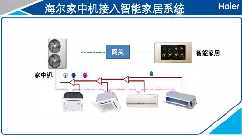
【海尔】海尔U-home与中央空调系统对接说明
- 格式:pdf
- 大小:1.38 MB
- 文档页数:18

海尔空调接线方法
海尔空调的接线方法主要包括以下几个步骤:
1. 确定电源接线位置:首先要确定空调的电源接线位置,一般在室内机的背面或顶部。
2. 拆开电源接线盖板:使用螺丝刀将电源接线盖板螺丝拆下,揭开盖板。
3. 接线连接:将电源线的火线(L)、零线(N)和地线(E)依次与空调的接线端子相对应地连接,一般通过螺丝将线缆牢固固定在空调接线端子上。
4. 接线盖板安装:将接线完成后,将接线盖板重新安装到空调上,螺丝固定。
5. 插座或开关连接:将空调主机的插头插入配电插座,或者将空调的开关与供电设备的开关连接,确保可正常接通电源。
6. 整理接线并检查:将接线整理好,不让线头暴露在外,并对接线进行检查,确保接线牢固可靠,没有松动现象。
以上是一般的空调接线方法,具体操作可参考产品说明书或咨询空调安装人员。
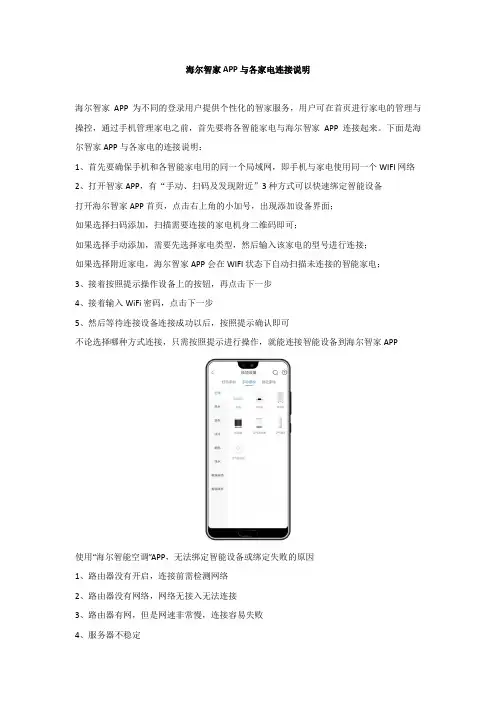
海尔智家APP与各家电连接说明
海尔智家APP为不同的登录用户提供个性化的智家服务,用户可在首页进行家电的管理与操控,通过手机管理家电之前,首先要将各智能家电与海尔智家APP连接起来。
下面是海尔智家APP与各家电的连接说明:
1、首先要确保手机和各智能家电用的同一个局域网,即手机与家电使用同一个WIFI网络
2、打开智家APP,有“手动、扫码及发现附近”3种方式可以快速绑定智能设备
打开海尔智家APP首页,点击右上角的小加号,出现添加设备界面;
如果选择扫码添加,扫描需要连接的家电机身二维码即可;
如果选择手动添加,需要先选择家电类型,然后输入该家电的型号进行连接;
如果选择附近家电,海尔智家APP会在WIFI状态下自动扫描未连接的智能家电;
3、接着按照提示操作设备上的按钮,再点击下一步
4、接着输入WiFi密码,点击下一步
5、然后等待连接设备连接成功以后,按照提示确认即可
不论选择哪种方式连接,只需按照提示进行操作,就能连接智能设备到海尔智家APP
使用“海尔智能空调”APP,无法绑定智能设备或绑定失败的原因
1、路由器没有开启,连接前需检测网络
2、路由器没有网络,网络无接入无法连接
3、路由器有网,但是网速非常慢,连接容易失败
4、服务器不稳定
5、安卓手机装有安全卫士,可能妨碍app的绑定,换个手机绑定或关闭安全卫士权限即可
6、wifi模块本身不良或wifi模块出现故障。

Central Controller U nit UMatch Inverter Systems MultiSplit Inverter SystemsTCONTADPYCJA2AConfidential and proprietary Trane informationA pril 2021Installation and operation manualMS-SVX081A-ENUser manuals and installation manuals for remote control detector TCONTADPYCJA2AFunctions IntroductionRemote control detector(short form:Detector)is essential equipment of remote monitor system of Haier commercial A/C.By connecting the interface in indoot units or outdoor units,this detector can reach functions of remote an central control◆Communication function1.with air conditioning communication:①. YCJ-A002 can at most connect two same model units by six-pin fixed screw. It canrealize double switching function. It can control air conditioning to work in different ways according to the requirement of detector, at the same time query the airconditioner's operation information and fault information.munication with RS-485:①. Communication with the central controllerBM1 dip switch as (1: OFF, 2: OFF)Communicate with the central controller via RS-485 interface bus (A, B). It receives commands from central controller according to the units address what is set by detector dip switch. And to realize internal control or query request, and answer the reception status and air conditioning operation information and fault information.②Communication with the central controllerBM1 dip switch as (1: ON, 2: OFF)Communicate with the central controller by RS-485 bus port. According to the detector within the dip switch setting address, Receive commands from the central controller. Have internal control or query request, and answer the reception status and air conditioning operation informationand fault information.③Communicate with remote devices. Detector has RS-485 port, and the protocol is Modbus RTU, users can use the private network and open protocol to create remote control program, no need other accessories.The BM1 dip switch as (1: OFF, 2: ON).④communication with the central control systemD ip switch BM1 (1: ON,2: ON)Communicate with the central control system by RS-485 bus port(A, B). it receives12commands from central controller according to the units address what is set by detector dip switch. And to realize internal control or query request, and answer the reception status and air conditioning operation information and fault information.In order to improve the reliability of air conditioning, the detector has double switching function, set SW1 to single unit mode, detector controls the A unit according to the command from the host equipment. Set SW1 to double switching mode, it can realize double switching function.Double switching function realization: under normal condition, the detector control one unit ON and another unit OFF, when reach the switch time, detector wake up the OFF state unit and the ON state unit will still work half an hour and then OFF.If any air conditioner has failure, switch time will stop, the detector automatically wake up another unit, and let the failure unit OFF, then upload the failure information. After the failure restore, automatically change to the double switching function; if air-conditioner operate for some time and cannot reach setting temperature, switch time will stop, the detector automatically wake up another air conditioner, double units operate until reaching the setting temperature, then automatically turn off that air conditioner, and automatically restore the double switching function. Factory default switch time is 12 hoursDetector has three lights, yellow light is for RS-485 communication , red and green lights are for the air conditioner communication, When the communication is normal, lights in accordance with the frequency of 0.5s flashing, when have failure, lights in according with the frequency of 1s flashing, stop 2s flashingThrough the RS-485 bus to build a central control network, In order to reduce the impact of unified operation of air conditioning on the power grid, the detector set the delay start function, the delay time is automatically generated by the detector【1】【2】BM10:OFF 1:ON numbe485communication mode details00①TCONTCCMYCZG1/TCONTCCMYCZ256 single unit10②/01③Modbus rtu standard protocol 11④BMS system◆Dual switch function◆Address setting function◆Operation status displasy function◆Delay control functionThe detector with 8-bit dip switch (SW1), the highest bit D8 bit, for setting the single mode or double-switch mode,(D7, D6, D5, D4, D3, D2, D1) is used to set the number (central control network or double switch time when select the dual switch mode)◆Double switching function instructions◆use central controller for central control functionSystem OverviewDetector connects with the two same model units through six-pin fixed screw. Set the dip switch to double switching model. Only use the double switching function, the system does not need connect the other components; double switching time can be chosen 8,10,12,14 hours by dip switch setting.the specific settings and the corresponding time see dip switch list12V 、COM 、GND ports of detector connect with air conditioner. Dip switch set to singlemode, the specific settings and the corresponding address see dip switch list, The system also needs to connect withcentral controller, Each detector connect with central Controller by 2-pin fix screw(A,B).DetectorsIndoor Unit Indoor UnitOutdoor Unit Outdoor Unit4◆Status check◆When servicing, be sure to power off the power supplyMaintenanceDimension drawing•When select the single unit mode and control A unit, when A unit failure occurs, the detector will query fault information and upload it, when select double switch mode,detectorcontrolA unit and B unit, if one of air conditioner is faulty, the detector will query the fault information and upload it•Detector operating status and running lamp display: When operation properly, running lamp for 0.5 seconds off 0.5 secondsfor a cycle to indicate,When have the fault to flash 1 second, stop 2 seconds to cycle to indicate, yellow lamp for the central control of communication status indication, red light for the air conditioner A unit communication Status indication, green lamp for air conditioning B unit communication status indication•Wipe clean with a soft cloth and be careful not to touch the electrical parts.•Do not use gasoline, thinner, decontamination powder, chemical wipes, etc. to avoid damage to electrical parts.•Check whether the wiring with the central control and air conditioning is normal, there is no broken wire or the existence of loosening of the connection.Interface Description:1-air conditioning A communication port,three-core shielded communication wire connection, wire length is not more than 10meter2-air conditioning B communication port,three-core shielded communication wire connection, wire length is not more than 10meter3 - dial switch is used for centralized control interface of detector detector Communication Associationand dual switching functionIOS device to achieve remote control.Installation and commissioning◆installation and wiring of the basic requirements:Use a screw driver to install detector, screw spacing see the right figure.Keep the detector on a wall or other reliable location to ensure that there is no water and other creatures that may cause failure to enter.1.Central control network design planning principles:(1) Detector, in order to maintain the appropriate response speed and communication reliability, the number of detectors in one central system should not exceed 64 pieces (2)A/C should be ready for network ,bu sure to be installed and us according to instructions(3) Detector installation position does not leave the air conditioner too far; do not exceed the wiring length(4) Detector address number in strict accordance with the order from small to large allocation(5) Detector power from the indoor unit, 12V, need have distance with the high voltage cable .and the shieldlayer needs earth one side(6) Central control bus wire length limit less than 1000 meters(7) both ends of the bus in the A bus and B bus were connected between the 100 ohm metal film precision resistance (depending on the scene to match)(8) bus shielded wire single point grounding, the proposed layout in the middle of the communication bus location, and centralized controller similar(9) Central controller installation location in principle arranged in the middle of the communication bus position, and the communication bus shield ground similar2.Detector and air conditioning connection: Detector through the air conditioning interface six screws fixed terminal (12V、COM1、GND、12V、COM2、GND) ,andup to two air-conditioning (A, B) for wired communication; detector and air conditioning connection with the uniform wiring, one end of the wiring terminal with plug connect to air conditioning indoor PCB remote control terminal. If the detector does not operation properly during commissioning, it can be check by change the wiring polarity + - . Also can be based on the running lamp show the operation status of the air conditioning and communication interface to determine whether the normal.3.After the communication bus wiring is completed, connect the detector and the communication bus: the connection method of hand by hand type, all A ports in the same Bus, all B ports on another bus, the communication bus shielding line in the communication bus in a single point of grounding, communication bus total length Limited to less than 1000 meters.◆According to the host equipment to select RS-485 interface protocol by dip switch BM1:Detector built a variety of different protocols to correspond to different host equipment, the use of four different protocols corresponding to four different conditions:1.The host equipment is a centralcontroller, central controller can choose to select the device type for single unit, in order to be able to deal with different system structure, the detector has two built-in protocols that communicate with the central controller.5①central controller, select the communication mode for the single unit, then dip switch: BM1: 1: OFF; 2: OFF.The system diagram is as follows:67②the host equipment for the third party communication equipment, the detector provides the standard Modbusrtu protocol, BM1 dip switch: 1: ON; 2: OFF, The communication between the detector and the air conditioner is consistent with the other 3. When the detector is used as a third-party protocol converter, it should be specificAccess to the requirements of third-party host device connection; the basic functions are as follows:The address of the address set by SW1 changes to the slave address in the Modbus RTU communicationSerial port9600,8,n ,1130B modbusrtu query01 control 05/15WORD name Unit Range Remarks 01 function code 0Indoor units on/off Read operation to obtain the current switchunit status 0: off 1: onWrite operation to change the switch state 0: off 1: on03 function code query 03 control 06/16 0I n t e r n a l s e t t i n g temperature ℃16-30Read operation Get current setting temperature, write operationChange set temperature1within the machine running mode 1--5Read operation to obtain the current operating mode: 1 - cooling 2 - heating 3 - dehumidification4 – Fan only5 - automatic Write operation to change the operating mode: 1 - cooling 2 - heating 3 - dehumidification 4 – Fan only 5 - automatic2Fan speed 1--4Read operation to obtain the current fan speed: 1 - low speed 2 – middle speed 3 - high speed4 – Automatic speedWrite operation to change the fan speed: 1 - low speed 2 – middle speed 3 - high speed 4 -Automatic speed3i n d o o r c o n t r o lmode1--4 1 is not locked; 2 empty - query back to 1, issued to write 1; 3 query back to 1,Issued to write 1; 4 - lock 04 function code read only 0indoortemp ℃301℃1Fault code 0-256within the indoor fault code 0-256 value of 0 that no error ,2machine numberThe number of internal indoor This address exists , query back 08◆Power test :◆RS485 interface dip switch instructions1.Power test: After the equipment is connected, the power test①first verify the detector and air conditioner communication status, the red lightshould be light 0.5 seconds off 0.5 seconds as a cycle to indicate, If the indicator does not light or flashes for 1 second and stops for 2 seconds, it should check whether the communication wire of the air conditioner and detector are the connection is correct and the air conditioner is powered up until the indicator flashes normally.②check 485 communication indicator (yellow lamp), should be light 0.5 seconds off 0.5seconds as a cycle to indicate, if the instructions If the lamp does not light or flashes for 1 second and stops for 2 seconds, it should check whether the BM1 protocol is correct; the communication wire is connectedWhether it is correct; whether there is a device with a repeated address, etc., until the indicator flashes normally2.The detector and the host equipment communication, if the host equipment to normal monitoring and control of air conditioners, the completion of debugging.Performance parameters and accessoriesDetector built a variety of different protocols to correspond to different equipment, the use of four different protocols corresponding to four different conditions:1.The host equipment is a centralcontroller, central controller can choose to select the device type for single unit , in order to be able to deal with different the system structure, the detector has two built-in protocols that communicate with the central controller.①central controller, select the communication mode for the unit, then dip switch BM1:1: OFF; 2: OFF.performance parameter DC12VPower consumption Power consumption is less than 3W Detector code number 0151800130BAccessoriesair conditioning communication 3 core shielded wire, special number 0010452854, color white, yellow, and redPerformance parameter9S W 1(1m e a n O N ,0 m e a n O F F )B M 1c o d e1:O F F ;2:O F F1:O N ;2:O F F 1:O F F ;2:O N 1:0N ;2:O N[1][2][3][4][5][6][7][8]D e fi n i t i o n : u n i t a r y a i r c o n d i t i o n e D e fi n i t i o n :V R F D e fi n i t i o n :M o d b u s R T U D e fi n i t i o n :B M S G a t e a d d r U n i t a d d r 1---0000D u a l m o d e a d d r =1D u a l m o d e a d d r =1-1D u a l m o d e s l a v e I D =1D u a l m o d e 3101---0001D u a l m o d e a d d r =2D u a l m o d e a d d r =2-2D u a l m o d e s l a v e I D =2D u a l m o d e 311—— —— —— —— —— —— 1---1110D u a l m o d e a d d r =15D u a l m o d e a d d r =15-15D u a l m o d e s l a v e I D =15D u a l m o d e 31141---1111D u a l m o d e a d d r =16D u a l m o d e a d d r =16-16D u a l m o d e s l a v e I D =16D u a l m o d e 3115-0000000S i n g l e m o d e a d d r =1S i n g l e m o d e a d d r =1-1S i n g l e m o d e s l a v e I D =1S i n g l e m o d e 310-0000001S i n g l e m o d e a d d r =2S i n g l e m o d e a d d r =2-2S i n g l e m o d e s l a v e I D =2S i n g l e m o d e 311—— —— —— —— —— —— -0100110S i n g l e m o d e a d d r =39S i n g l e m o d e a d d r =39-39S i n g l e m o d e s l a v e I D =39S i n g l e m o d e 3138-0100111S i n g l e m o d e a d d r =40S i n g l e m o d e a d d r =40-40S i n g l e m o d e s l a v e I D =40S i n g l e m o d e 3139-0101000S i n g l e m o d e a d d r =41S i n g l e m o d e a d d r =41-41S i n g l e m o d e s l a v e I D =41S i n g l e m o d e 300-0101001S i n g l e m o d e a d d r =42S i n g l e m o d e a d d r =42-42S i n g l e m o d e s l a v e I D =42S i n g l e m o d e 301—— —— —— —— —— —— -1001110S i n g l e m o d e a d d r =79S i n g l e m o d e a d d r =79-79S i n g l e m o d e s l a v e I D =79S i n g l e m o d e 3038-1001111S i n g l e m o d e a d d r =80S i n g l e m o d e a d d r =80-80S i n g l e m o d e s l a v e I D =80S i n g l e m o d e 3039-1010000S i n g l e m o d e a d d r =81S i n g l e m o d e a d d r =81-81S i n g l e m o d e s l a v e I D =81S i n g l e m o d e 290-1010001S i n g l e m o d e a d d r =82S i n g l e m o d e a d d r =82-82S i n g l e m o d e s l a v e I D =82S i n g l e m o d e 291—— —— —— —— —— —— -1110110S i n g l e m o d e a d d r =119S i n g l e m o d e a d d r =119-119S i n g l e m o d e s l a v e I D =119S i n g l e m o d e 2938-1110111S i n g l e m o d e a d d r =120S i n g l e m o d e a d d r =120-120S i n g l e m o d e s l a v e I D =120S i n g l e m o d e 2939-1111000S i n g l e m o d e a d d r =121S i n g l e m o d e a d d r =121-121S i n g l e m o d e s l a v e I D =121S i n g l e m o d e 280-1111001S i n g l e m o d e a d d r =122S i n g l e m o d e a d d r =122-122S i n g l e m o d e s l a v e I D =122S i n g l e m o d e 281—— —— —— —— —— —— -1111110S i n g l e m o d e a d d r =127S i n g l e m o d e a d d r =127-127S i n g l e m o d e s l a v e I D =127S i n g l e m o d e 286-1111111S i n g l e m o d e a d d r =128S i n g l e m o d e a d d r =128-128S i n g l e m o d e s l a v e I D =128S i n g l e m o d e 287◆ Address setting functionSW01Definition[1][2][3][4][5][6][7][8]0———————Single mode 1———————Double Switch mode —00—————Double Switch time 8 hours —01—————Double Switch time 10 hours —10—————Double Switch time 12 hours —11—————Double Switch time 24 hours———0————Dual operation at ambient temperature of 34℃———1————Dual operation at ambient temperature of 32℃1———0000Double Switch mode and ad-dress=11———0001Double Switch mode and ad-dress=2———1———1110Double Switch mode and ad-dress=151———1111Double Switch mode and ad-dress=1600000000Single mode and address=100000001Single mode and address=2———01111110Single mode and address=12701111110Single mode and address=12810Trane - by Trane Technologies (NYSE: TT), a global climate innovator - creates comfortable, energy efficient indoor environments for commercial and residential applications. For more information, please visit or .Trane has a policy of continuous product and product data improvement and reserves the right to change design and specifications without notice. We are committed to using environmentally conscious print practices.©2020 TraneConfidential and proprietary Trane information。
目录第一章公司简介 (2)第二章系统设计理念 (3)第三章系统设计原则 (4)第四章系统总体设计 (5)4.1系统概述及特点 (5)4.2项目概况 (5)4.3需求分析 (5)4.4系统总体设计 (6)4.4.1 可视对讲 (6)4.4.2 家居安防 (7)4.4.3 智慧家居 (7)第五章系统功能介绍 (12)5.1 对讲系统 (12)5.2 安防系统 (12)5.2.1 紧急求救 (12)5.2.2 报警信息实时记录功能 (12)5.2.3 报警信息短信报警,上报用户手机 (13)5.2.4 劫持报警功能 (13)5.2.5周界防范系统具备阻挡能力 (13)5.3.1 灯光控制 (13)5.3.2 窗帘控制 (14)5.3.3 模式控制 (14)5.3.4 情景控制 (15)5.3.5 第三方系统控制 (15)5.4 网关联合控制功能 (15)第六章系统设备介绍 (17)6.1 61系列系统介绍 (17)6.1.1 智能终端介绍 (17)6.1.2 设备参数介绍 (17)6.1.3 设备功能简介 (17)6.1.4系统优势与特色 (18)6.2 别墅门口机 (19)6.3 智能触控面板 (19)7.3.1 智能触控面板-HK-50Q6CW (19)7.3.2 智能触控面板-HK-50P6CW (20)7.3.3 智能触控面板-HK-50P4CW (21)6.4 电动窗帘 (22)6.5 家庭网络中心 (23)6.6 智能门锁6.7 RISCO无线安防系统第七章售后服务 (27)第一章公司简介青岛海尔智能家电科技有限公司,隶属于海尔集团,企业注册资金1.8亿,是全球领先的智能家电家居产品研发制造基地。
海尔U-home在智能家电家居的研发和生产方面,拥有多项专利和自主专用技术,负责起草制定家庭网络国家标准及国际标准。
海尔U-home拥有近二十名博士在内的高素质智能家电家居专业研发团队,从事智能家电、数字变频、无线高清音视频解码、网络通信及UWB、蓝牙、RF、电力载波等技术的研发,并整合全球资源网络,与多家国际知名企业建立联合开发实验室,提出了云家庭、云社区、云服务、智能住宅、智能社区、智能安防、视频监控、系统集成、智慧用电等解决方案。

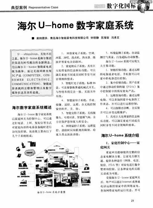
海尔U-Home智能家居设计方案目录一、海尔U-Home数字智能家居概述 (3)二、系统设计依据 (5)三、U-home智能家居特点 (5)3.1先进的标准,保证了不同厂商不同设备的连接 (5)3.2全数字通信方式,节省布线,降低成本 (6)3.3完善的产品功能 (6)3.4时尚的外观,人性化操作 (6)3.5先进的无线控制方式 (6)3.6过硬的产品质量 (7)3.7专业的设计和安装 (7)3.8星级售后服务 (7)四、U-Home智能家居LOFT解决方案 (8)4.1系统概述 (9)4.2系统功能介绍 (10)4.2.1可视对讲/门铃 (10)4.2.2智能家居控制 (11)4.2.3家居安全防范 (13)4.2.4背景音乐 (15)4.3场景模式 (17)4.3.1起床模式 (17)4.3.2起夜模式 (17)4.3.3影音模式 (18)五、U-Home主要产品介绍 (19)5.1智能终端 (19)5.2家庭网络中心 (20)5.3智能触控面板 (21)5.4智能插座 (22)5.5红外转发器 (22)5.6智能门锁 (23)六、设备清单 (24)一、海尔U-Home数字智能家居概述智能家居是指利用先进的计算机技术、网络通信技术、综合布线技术,将与家居生活有关的名种子系统,有机地结合在一起,通过统筹管理,让家居生活更加舒适、安全、有效。
与普通的家居相比,智能家居不公具有传统的居住功能,提供舒适安全、高品位且宜人的空话生活空间;还由原来的被动静止结构转变为具有能动智慧的工具,帮助家庭与外部保持信息交流畅通,优化人们的生活方式,甚至为各种能源支出节约资金。
智能家居的基本目标是:将家庭中各种与信息相关的通信设备,家用电器和家庭保安装置通过家庭总线技术(HBS)连接到一个家庭智能化系统上进行集中的或者异地的监视、控制和家庭事务性管理,交保持这些家庭设施与住宅环境的和谐与协调。
U—ubiquitous,无处不在之意。
中央空调系统安装说明简介:本文档旨在提供中央空调系统的安装说明和操作指南,以确保正确和安全地安装系统。
请在进行安装之前详细阅读本文档。
安装前准备在安装中央空调系统之前,请确保已经完成以下准备工作:1. 确定安装位置:选择一个适合安装中央空调系统的位置,确保空调各部件之间的空间足够,并有必要的通风设施。
2. 检查电源:确保安装位置附近有稳定的电源供应,并满足系统的电气需求。
3. 准备安装材料:收集所需的安装材料,如管道、电线、支架等。
4. 确定管道布局:根据建筑结构和空调系统布局,确定管道的安装路径和连接方式。
安装步骤按照以下步骤进行中央空调系统的安装:1. 安装室外机:根据制定的管道布局,确定室外机的安装位置,并使用适当的支架固定。
连接室外机的电源和管道。
2. 安装室内机:根据安装计划,确定室内机的位置,并使用支架将它固定在适当的位置。
连接室内机的电源和管道。
3. 连接管道:在室外机和室内机之间连接必要的管道,并确保连接处密封良好,无泄漏。
4. 连接电源:将中央空调系统的电源线接入到适当的电源插座,并测试电源供应是否正常。
5. 完成安装:仔细检查所有连接是否牢固,确保系统的安装符合标准。
操作指南中央空调系统安装完成后,按照以下操作指南使用系统:1. 打开系统:使用遥控器或控制面板,将中央空调系统的电源打开。
2. 设定温度:根据需要,设置室内温度。
系统将自动调节温度并保持室内舒适。
3. 调节风速:根据需要,调节风扇的速度。
可以选择高、中、低三档风速。
4. 模式选择:根据需要选择制冷模式或制热模式。
系统会自动根据设置的温度进行调节。
5. 定时开关:可以设置定时开关机功能,让系统在预定时间自动开关。
维护和保养为确保中央空调系统的正常运行和延长使用寿命,定期进行以下维护和保养:1. 清洁过滤器:定期清洁室内机的过滤器,以保持良好的空气质量和系统性能。
2. 检查管道:定期检查管道连接处是否泄漏,如有需要,进行及时修复。
SIMATIC 545/555/575 System ManualOrder Number: PPX:505-8201-3 Manual Assembly Number: 2804693-0003 Third EditionCopyright 2000 by Siemens Energy & Automation, Inc.All Rights Reserved — Printed in USAReproduction, transmission, or use of this document or contents is not permitted without express consent ofSiemens Energy & Automation, Inc. All rights, including rights created by patent grant or registration of a utility model or design, are reserved.Since Siemens Energy & Automation, Inc., does not possess full access to data concerning all of the uses and applications of customer’s products, we do not assume responsibility either for customer product design or for any infringements of patents or rights of others which may result from our assistance.MANUAL PUBLICATION HISTORYSIMATIC 545/555/575 System ManualOrder Manual Number: PPX:505–8201–3Refer to this history in all correspondence and/or discussion about this manual. Event Date DescriptionOriginal Issue03/96Original Issue (2804693–0001) Second Edition08/98Second Edition (2804693–0002) Third Edition06/00Third Edition (2804693–0003)LIST OF EFFECTIVE PAGESPages Description Pages DescriptionCover/Copyright Third EditionHistory/Effective Pages Third Editioniii — xxi Third Edition1-1 — 1-13Third Edition2-1 — 2-20Third Edition3-1 — 3-28Third Edition4-1 — 4-58Third Edition5-1 — 5-24Third Edition6-1 — 6-35Third Edition7-1 — 7-12Third Edition8-1 — 8-8Third Edition9-1 — 9-25Third EditionA-1 — A-5Third EditionB-1 — B-9Third EditionC-1 — C-23Third EditionD-1 — D-7Third EditionE-1 — E-16Third EditionF-1 — F-6Third EditionIndex-1 — Index-10Third EditionRegistration Third EditionContentsPrefaceChapter 1System Overview. . . . . . . . . . . . . . . . . . . . . . . . . . . . . . . . . . . . . . . . . . . . . . . . . . . . . . . . . . . . . . . . . . . . . . .1.1Overview1-2. . . . . . . . . . . . . . . . . . . . . . . . . . . . . . . . . . . . . . . . . . . . . . . . . . . . . . . . . . . . . . . . . . . .Introduction1-2. . . . . . . . . . . . . . . . . . . . . . . . . . . . . . . . . . . . . . . . . . . . . . . .Compatibility with Previous CPUs1-2. . . . . . . . . . . . . . . . . . . . . . . . . . . . . . . . . . . . . . . . . . . . . . . . . . .Features on New CPU Models1-3 . . . . . . . . . . . . . . . . . . . . . . . . . . . . . . . . . . . . . . . . . . . . . . . . . . . . . . . . . . . . . . . . . . .PROFIBUS-DP1-4. . . . . . . . . . . . . . . . . . . . . . . . . . . . . . . . . . . . . . . . . . . . . . . . . . . .PROFIBUS User Organizations1-4. . . . . . . . . . . . . . . . . . . . . . . . . . . . . . . . . . . . . . . . . . . . . . . . . . . . . . . . . . .Using Other Networks1-4. . . . . . . . . . . . . . . . . . . . . . . . . . . . . . . . . . . . . . . . . . . . . . . . . . . . . . . . . . . . . . . .1.2System Features1-6Product Specifications Overview1-6. . . . . . . . . . . . . . . . . . . . . . . . . . . . . . . . . . . . . . . . . . . . . . . .. . . . . . . . . . . . . . . . . . . . . . . . . . . . . . . . . . . . . . . . . . . . . . . . . . . . . . . . . . . . . . . .Shared Features1-8. . . . . . . . . . . . . . . . . . . . . . . . . . . . . . . . . . . . . . . . . . . . . . . . . . . . . . . . . .545/555-Only Features1-9. . . . . . . . . . . . . . . . . . . . . . . . . . . . . . . . . . . . . . . . . . . . . . . . . . . . . . . . . . . . . . .575-Only Features1-10. . . . . . . . . . . . . . . . . . . . . . . . . . . . . . . . . . . . . . . . . . . . . . . . . . . . . . . . . . . . . .1.3Programming Tools1-11. . . . . . . . . . . . . . . . . . . . . . . . . . . . . . . . . . . . . . . . . . . . . . . . . . . . . . . . . . . . . . . . . . . . . . .SoftShop1-11 . . . . . . . . . . . . . . . . . . . . . . . . . . . . . . . . . . . . . . . . . . . . . . . . . . . . . . . . . . . . . . . . . . . . . . . . . .TISOFT1-11 . . . . . . . . . . . . . . . . . . . . . . . . . . . . . . . . . . . . . . . . . . . . . . . . . . . . . . . . . . . . . . . . .COM PROFIBUS1-11. . . . . . . . . . . . . . . . . . . . . . . . . . . . . . . . . . . . . . . . . . . . . . . . . . .Communicating with the CPU1-11. . . . . . . . . . . . . . . . . . . . . . . . . . . . . . . . . . . . . . . . . . . . . . . . . . . . . . . . . . . . .1.4Hardware Overview1-12. . . . . . . . . . . . . . . . . . . . . . . . . . . . . . . . . . . . . . . . . . . . . . . . . . . . . . . . . . . . . . . . .Series 505 Bases1-12 . . . . . . . . . . . . . . . . . . . . . . . . . . . . . . . . . . . . . . . . . . . . . . . . . . . . . . . . . . . . . . . . . . . . . .VME Base1-12 . . . . . . . . . . . . . . . . . . . . . . . . . . . . . . . . . . . . . . . . . . . . . . . . . . . . . . . . . . . . . . . . . .Expansion I/O1-13. . . . . . . . . . . . . . . . . . . . . . . . . . . . . . . . . . . . . . . . . . . . . . . . . . . . . . . . . . . .I/O Channel Support1-13 Chapter 2Pre-installation Guidelines. . . . . . . . . . . . . . . . . . . . . . . . . . . . . . . . . . . . . . . . . . . . . . . . . . . . . . . .2.1Planning Your Installation2-2. . . . . . . . . . . . . . . . . . . . . . . . . . . . . . . . . . . . . . . . . . . . . . . . . .Defining Control Requirements2-2 Calculating Power Needs2-2. . . . . . . . . . . . . . . . . . . . . . . . . . . . . . . . . . . . . . . . . . . . . . . . . . . . . . .. . . . . . . . . . . . . . . . . . . . . . . . . . . . . . . . . . . . . . . . . . . . . . . . . . . . . . . . . . .2.2Safety Considerations2-3Operator Safety Switches2-4. . . . . . . . . . . . . . . . . . . . . . . . . . . . . . . . . . . . . . . . . . . . . . . . . . . . . . .. . . . . . . . . . . . . . . . . . . . . . . . . . . . . . . . . . . . . . . . . . . . . . . . . . . . . . . . .Emergency Stop Switch2-4. . . . . . . . . . . . . . . . . . . . . . . . . . . . . . . . . . . . . . . . . . . . . . . . . . . . . . . . . . . . .JOG or INCH Switch2-5 2.3575 Fault Relay Operation2-6. . . . . . . . . . . . . . . . . . . . . . . . . . . . . . . . . . . . . . . . . . . . . . . . . . . . . . .. . . . . . . . . . . . . . . . . . . . . . . . . . . . . . . . . . . . . . . . . . . . . . . . . . . . . . . . . . . . . . . . . . . . . . .Overview2-6. . . . . . . . . . . . . . . . . . . . . . . . . . . . . . . . . . . . . . . . . . . . . . . . . . . .Fault Relay Operation Details2-6 . . . . . . . . . . . . . . . . . . . . . . . . . . . . . . . . . . . . . . . . . . . . . . . . . . . . . . . . . . . . . . . . . . . . .Time Delay2-8. . . . . . . . . . . . . . . . . . . . . . . . . . . . . . . . . . . . . . . . . . . . . . . . . . . . .Fault Relay Usage Examples2-8Contents iii2.4Guidelines for Fuses/Circuit Breakers2-11. . . . . . . . . . . . . . . . . . . . . . . . . . . . . . . . . . . . . . . . . . . . .. . . . . . . . . . . . . . . . . . . . . . . . . . . . . . . . . . . . . . .Fusing the Controller and Remote I/O Base2-11 . . . . . . . . . . . . . . . . . . . . . . . . . . . . . . . . . . . . . . . . . . . . . . . . . . . . . . . . . . . . . . . . .2.5Electrical Noise2-12Definition and Source2-12. . . . . . . . . . . . . . . . . . . . . . . . . . . . . . . . . . . . . . . . . . . . . . . . . . . . . . . . . . .. . . . . . . . . . . . . . . . . . . . . . . . . . . . . . . . . . . . . . . . . . . . . . . . . . . . . .2.6Correcting Noise Problems2-13. . . . . . . . . . . . . . . . . . . . . . . . . . . . . . . . . . . . . . . . . . . . . . . . . . . . . . . . . . . . . . . . .Noise Snubbing2-13 . . . . . . . . . . . . . . . . . . . . . . . . . . . . . . . . . . . . . . . . . . . . . . . . . . . . . . . . . . . . . . . . . .Noise Isolation2-15. . . . . . . . . . . . . . . . . . . . . . . . . . . . . . . . . . . . . . . . . . . . . . . . . . . . . . . . . . . . . . .2.7Wiring Guidelines2-16. . . . . . . . . . . . . . . . . . . . . . . . . . . . . . . . . . . . . . . . . . . . . . . . . . . .2.8Grounding the Power System2-17Earth Ground2-17 . . . . . . . . . . . . . . . . . . . . . . . . . . . . . . . . . . . . . . . . . . . . . . . . . . . . . . . . . . . . . . . . . . .. . . . . . . . . . . . . . . . . . . . . . . . . . . . . . . . . . . . . . . . . . . . . . . . . . . . . . . . . . .Ground Connections2-18. . . . . . . . . . . . . . . . . . . . . . . . . . . . . . . . . . . . . . . .Grounding the 545/555 Controller Chassis2-19. . . . . . . . . . . . . . . . . . . . . . . . . . . . . . . . . . . . . . . . . . . . . . . . .Grounding the Cabinet or Rack2-19. . . . . . . . . . . . . . . . . . . . . . . . . . . . . . . . . . . . . . . . . . . . . . . . .Cable Management for the 5752-20. . . . . . . . . . . . . . . . . . . . . . . . . . . . . . . . . . . . . . . . . . . .Grounding the 575 Controller Chassis2-20 Grounding the Cabinet or Rack2-20. . . . . . . . . . . . . . . . . . . . . . . . . . . . . . . . . . . . . . . . . . . . . . . . . Chapter 3Installing 505 System Hardware. . . . . . . . . . . . . . . . . . . . . . . . . . . . . . . . . . . . . . . . . . . . . .3.1Overview of Installation Procedures3-2. . . . . . . . . . . . . . . . . . . . . . . . . . . . . . . . . . . . . .3.2Enclosure and Temperature Considerations3-3. . . . . . . . . . . . . . . . . . . . . . . . . . . . . . . . . . . . . . . . . . . . . . . . . . . . . . . . . . . . .Enclosure Selection3-3. . . . . . . . . . . . . . . . . . . . . . . . . . . . . . . . . . . . . . . . . . . . . . . . . . . . .Temperature Considerations3-3. . . . . . . . . . . . . . . . . . . . . . . . . . . . . . . . . . . . . . . . . . . . . . . . . . . . . . . . . . . . . . . .3.3Series 505 Bases3-4. . . . . . . . . . . . . . . . . . . . . . . . . . . . . . . . . . . . . . . . . . . . . . . . . . . . . . . . . . . . . . . . . . . . .Description3-4. . . . . . . . . . . . . . . . . . . . . . . . . . . . . . . . . . . . . . . . . . . . . . . .Grounding the Controller Chassis3-4. . . . . . . . . . . . . . . . . . . . . . . . . . . . . . . . . . . . . . . . . . . . . . . . .3.4Rack Mounting Series 505 Bases3-5. . . . . . . . . . . . . . . . . . . . . . . . . . . . . . . . . . . . . . . . . . . . . . . . .3.5Panel Mounting Series 505 Bases3-6. . . . . . . . . . . . . . . . . . . . . . . . . . . . . . . . . . . . . . . . . . . . . . . .3.6Installing Series 505 Power Supply3-8Power Budget for Series 505 Base3-8. . . . . . . . . . . . . . . . . . . . . . . . . . . . . . . . . . . . . . . . . . . . . . . .. . . . . . . . . . . . . . . . . . . . . . . . . . . . . . . . . . . . . . . . . . . . . . . .Power Supply Placement in Bases3-8. . . . . . . . . . . . . . . . . . . . . . . . . . . . . . . . . . . . . . .Installing and Removing the Power Supply3-8 Wiring the Power Supply3-10. . . . . . . . . . . . . . . . . . . . . . . . . . . . . . . . . . . . . . . . . . . . . . . . . . . . . . . . .. . . . . . . . . . . . . . . . . . . . . . . . . . . . . . . .3.7Installing the PROFIBUS-DP Annex Card (Optional)3-12. . . . . . . . . . . . . . . . . . . . . . . . . . . . . . . . . . . . . . . . . . . . . . . . . . . . . . .3.8Installing the 545/555 CPU3-14. . . . . . . . . . . . . . . . . . . . . . . . . . . . . . . . . . . . . . . . . . . . . . . . . . . . .CPU/RBC Location in a Base3-14. . . . . . . . . . . . . . . . . . . . . . . . . . . . . . . . . . . . . . . . . . . . . . . .Installing and Removing the CPU3-14iv Contents3.9Replacing and Handling the Battery3-16. . . . . . . . . . . . . . . . . . . . . . . . . . . . . . . . . . . . . . . . . . . . .. . . . . . . . . . . . . . . . . . . . . . . . . . . . . .Lithium Battery in the 545 and 555 –1105/–1106 CPUs3-16. . . . . . . . . . . . . . . . . . . . . . . . . . . . . . . . . . . . . . .Replacing the Battery in –1105/–1106 CPUs3-17 Lithium Battery in the 545 and 555 –1103/–1104 CPUs3-18. . . . . . . . . . . . . . . . . . . . . . . . . . . . . .. . . . . . . . . . . . . . . . . . . . . . . . . . . . . . . . . . . . . . . . . . . . . . . . . . . . . . . . . . . . . . . . . . . . . .Indicators3-18. . . . . . . . . . . . . . . . . . . . . . . . . . . . . . . . . . . . . . . . . . . . . . . . . . . .Using and Handling Batteries3-19. . . . . . . . . . . . . . . . . . . . . . . . . . . . . . . . . . . . . . . . . . . . . . . . . . . . . . . . . . .Transporting Batteries3-19. . . . . . . . . . . . . . . . . . . . . . . . . . . . . . . . . . . . . . . . . . . . . . . . . . . . . . . . . . . . . . . .Storing Batteries3-19. . . . . . . . . . . . . . . . . . . . . . . . . . . . . . . . . . . . . . . . . . . . . . . . . . . . . . . . . . . . .Discarding Batteries3-19. . . . . . . . . . . . . . . . . . . . . . . . . . . . . . . . . . . . . . .Replacing the Battery in –1103/–1104 CPUs3-20. . . . . . . . . . . . . . . . . . . . . . . . . . . . . . . . . . . . . . . . . . . . . . . . . . . . .3.10Setting the CPU Dipswitches3-22. . . . . . . . . . . . . . . . . . . . . . . . . . . . . . . . . . . . . . . . . . . . . . . . .Dipswitch Location and Settings3-22. . . . . . . . . . . . . . . . . . . . . . . . . . . . . . . . . . . . . . . . . . . . . . . . . . . . . . . .Enabling Battery Backup3-22. . . . . . . . . . . . . . . . . . . . . . . . . . . . . . . . . . . . . . . . . . .Enabling the Auto Recompile Function3-22. . . . . . . . . . . . . . . . . . . . . . . . . . . . . . . . . . . . . . . . . . . . . . . . . . . . . . . . . . . . . .Setting Baud Rates3-23 Communications Port 13-24. . . . . . . . . . . . . . . . . . . . . . . . . . . . . . . . . . . . . . . . . . . . . . . . . . . . . . . . .. . . . . . . . . . . . . . . . . . . . . . . . . . . . . . . . . . . . . . . . . . . . . . . . . . . . . . . . .Communications Port 23-24 . . . . . . . . . . . . . . . . . . . . . . . . . . . . . . . . . . . . . . . . . . . . . . . . . . . . . . . . . . . . . . . . . . . . . . . .I/O Ports3-25 3.11Installing Series 505 I/O Modules3-26. . . . . . . . . . . . . . . . . . . . . . . . . . . . . . . . . . . . . . . . . . . . . . . . .. . . . . . . . . . . . . . . . . . . . . . . . . . . . . . . . . . . . . . . . . . . . . . . . . . . . . . . . . . . . .Mixing I/O Modules3-26 Installing and Removing I/O Modules3-26. . . . . . . . . . . . . . . . . . . . . . . . . . . . . . . . . . . . . . . . . . . . Chapter 4Installing 575 System Hardware. . . . . . . . . . . . . . . . . . . . . . . . . . . . . . . . . . . . . . . . . . . . . .4.1Overview of Installation Procedures4-2. . . . . . . . . . . . . . . . . . . . . . . . . . . . . . . . . . . . . . .4.2Features of the PPX:575–2130 VMEbus Base4-3. . . . . . . . . . . . . . . . . . . . . . . . . . . . . . . . . . . . . . . . . . . . . . . . . . . . . . . . . . . . . . . . . . . . . . .Overview4-3. . . . . . . . . . . . . . . . . . . . . . . . . . . . . . . . . .4.3Features Required of a Third-Party VMEbus Base4-4. . . . . . . . . . . . . . . . . . . . . . . . . . . . . . . . . . . . . . . . . . . . . . . . . . . . .VMEbus Base Requirements4-4. . . . . . . . . . . . . . . . . . . . . . . . . . . . . . . .Determining the Condition of the 575 CPU Battery4-4. . . . . . . . . . . . . . . . . . . . . . . . . . . . . . . . . . . . . .4.4Enclosure and Temperature Considerations4-5. . . . . . . . . . . . . . . . . . . . . . . . . . . . . . . . . . . . . . . . . . . . . . . . . . . . . . . . . . . . .Enclosure Selection4-5. . . . . . . . . . . . . . . . . . . . . . . . . . . . . . . . . . . . . . . . . . . . . . . . . . . . .Temperature Considerations4-5. . . . . . . . . . . . . . . . . . . . . . . . . . . . . . . . . . . . . . . . . . . . . . . . . . . . . .4.5Installing the Fan Assembly4-6. . . . . . . . . . . . . . . . . . . . . . . . . . . . . . . . . . . . . . . . . . . . . . . . . . .Operating With Fan Assembly4-6. . . . . . . . . . . . . . . . . . . . . . . . . . . . . . . . . . . . . . . . . . . . . . . .Operating Without Fan Assembly4-6. . . . . . . . . . . . . . . . . . . . . . . . . . . . . . . . . . . . . . . . . . . . . . . . . . . . . . . . . . .Installation Sequence4-6 Selecting Voltage for Fan Operation4-7. . . . . . . . . . . . . . . . . . . . . . . . . . . . . . . . . . . . . . . . . . . . .. . . . . . . . . . . . . . . . . . . . . . . . . . . . . . . . . . . . . . . . . . . . . . . . . . .Wiring the AC Power Terminals4-7. . . . . . . . . . . . . . . . . . . . . . . . . . . . . . . . . . . . . . . . . . . . . . . . . . . . .Mounting the Fan Assembly4-8 Replacing Fuse on the Fan Assembly4-9. . . . . . . . . . . . . . . . . . . . . . . . . . . . . . . . . . . . . . . . . . . . .Contents v. . . . . . . . . . . . . . . . . . . . . . . . . . . . . . . . . . . . . . . . .4.6Installing the PPX:575–2130 VMEbus Base4-10. . . . . . . . . . . . . . . . . . . . . . . . . . . . . . . . . . . . . . . . . . . . . . . . . . . . . . . . . . . . .Mechanical Outline4-10. . . . . . . . . . . . . . . . . . . . . . . . . . . . . . . . . . . . . . . . . . . . . . . . . . . . . . . .Mounting Measurements4-10. . . . . . . . . . . . . . . . . . . . . . . . . . . . . . . . . . . . . . . . . . . . . .Mounting a Base in a 19-inch Rack4-11. . . . . . . . . . . . . . . . . . . . . . . . . . . . . . . . . . . . . . . . .NEMA Cabinet Mounting Measurements4-12. . . . . . . . . . . . . . . . . . . . . . . . . . . . . . . . . . . . . . . . . . . . . . . . . . . . . . . .Panel Mounting the Base4-12. . . . . . . . . . . . . . . . . . . . . . . . . . . . . . . . . . . . . . . . . . . . . . . .Grounding the Controller Chassis4-13. . . . . . . . . . . . . . . . . . . . . . . . . . . . . . . . . . . . . . . . . . . . . . . . . .4.7Installing the 575 Power Supply4-14Overview4-14 . . . . . . . . . . . . . . . . . . . . . . . . . . . . . . . . . . . . . . . . . . . . . . . . . . . . . . . . . . . . . . . . . . . . . . .. . . . . . . . . . . . . . . . . . . . . . . . . . . . . . . . . . . . .Selecting Input Voltage (PPX:575–6663 Only)4-16. . . . . . . . . . . . . . . . . . . . . . . . . . . . . . . . . . . . . . . . . . . . . . . . . .Installing the 575 Power Supply4-17. . . . . . . . . . . . . . . . . . . . . . . . . . . . . . . . . . . . . . . . . . . . . . . . . . . . . . . . . . . . . . .Wiring Guidelines4-17. . . . . . . . . . . . . . . . . . . . . . . . . . . . . . . . . . . . . . . . . . . . . . . . . . . . . . . . . . . . . . .Wiring Procedure4-18. . . . . . . . . . . . . . . . . . . . . . . . . . . . . . . . . . . . . . . . . . . . . . . . . . . . . . . . . . . .4.8Installing the Battery4-20Battery Backup for the 5754-20. . . . . . . . . . . . . . . . . . . . . . . . . . . . . . . . . . . . . . . . . . . . . . . . . . . . . .. . . . . . . . . . . . . . . . . . . . . . . . . . . . . . . . . . . . . . . . . . . . . . . . . . . . . . . . . . .Mounting the Battery4-20. . . . . . . . . . . . . . . . . . . . . . . . . . . . . . . . . . . . . . . . . . . . . . . . . . . . . . . . . . . .Disabling the Battery4-22 Battery Fuse4-22 . . . . . . . . . . . . . . . . . . . . . . . . . . . . . . . . . . . . . . . . . . . . . . . . . . . . . . . . . . . . . . . . . . . .. . . . . . . . . . . . . . . . . . . . . . . . . . . . . . .4.9Installing the Floating-Point Coprocessor (Optional)4-23. . . . . . . . . . . . . . . . . . . . . . . . . . . . . . . . . . . . . . . . . . . . . . . . . . . . . . . . . . . .4.10Configuring the CPU4-24Configuring the 575–2105/–2106 CPU4-24. . . . . . . . . . . . . . . . . . . . . . . . . . . . . . . . . . . . . . . . . . . .. . . . . . . . . . . . . . . . . . . . . . . . . . . . . . . . . . . . . . . . . . . . . . . . . . .Configuring the 575–2104 CPU4-24. . . . . . . . . . . . . . . . . . . . . . . . . . . . . . . . . . . . . . . . . . . . .Using the AUTO-CONFIGURED Mode4-26. . . . . . . . . . . . . . . . . . . . . . . . . . . . . . . . . . . . . . . . . . . . . .Using the USER-CONFIGURED Mode4-26. . . . . . . . . . . . . . . . . . . . . . . . . . . . . . . . . . . .Configuring the 575 Primary and Secondaries4-26. . . . . . . . . . . . . . . . . . . . . . . . . . . . . . . . . . . . . . . . . . .Enabling the Auto Recompile Function4-26. . . . . . . . . . . . . . . . . . . . . . . . . . . . . . . . . . . . . . . . . . . . . . . . . . . . . . . .Setting the Base Address4-27 . . . . . . . . . . . . . . . . . . . . . . . . . . . . . . . . . . . . . . . . . . . . . . . . . . . . . . . . . . . . . . . . .Issuing SYSRESET4-27. . . . . . . . . . . . . . . . . . . . . . . . . . . . . . . . . . .4.11Installing a Remote I/O Annex Card (Optional)4-28. . . . . . . . . . . . . . . . . . . . . . . . . . . . . . . . . . . . . . . . . . . . . .Configuring Annex Card Dipswitch4-28. . . . . . . . . . . . . . . . . . . . . . . . . . . . . . . . . . . . . . . . . . . . . . . .Annex Card Power Consumption4-28 Installing the Series 505 Remote I/O Annex Card4-29. . . . . . . . . . . . . . . . . . . . . . . . . . . . . . . . . .. . . . . . . . . . . . . . . . . . . . . . . . . . . . . . . . . . . . . . . . . . .Installing the PROFIBUS-DP Annex Card4-30. . . . . . . . . . . . . . . . . . . . . . . . . . . . . . . . . . . . . . . . . . . . . . . . . . . . . . . .4.12Installing VMEbus Boards4-32. . . . . . . . . . . . . . . . . . . . . . . . . . . . . . . . . . . . . . . . . . . . . . . . . . . . . . . . . . . . . . . . . . . .Introduction4-32. . . . . . . . . . . . . . . . . . . . . . . . . . . . . . . . . . . . . . . . . . . . . . . . . . . . . . . . . . . . .General Guidelines4-34. . . . . . . . . . . . . . . . . . .Guidelines for Installing a 575 System Controller or a Primary 5754-35 Guidelines for Installing or Adding a 575 Secondary to the System4-36. . . . . . . . . . . . . . . . .. . . . . . . . . . . . . . . . . . . . . . . . . . . . . . . . .Guidelines for Replacing a 575 System Controller4-37. . . . . . . . . . . . . . . . . . . . . . . . . . . . . . .Guidelines for Replacing a 575 Primary Not in Slot 14-38 Guidelines for Replacing a 575 Secondary4-39. . . . . . . . . . . . . . . . . . . . . . . . . . . . . . . . . . . . . . .. . . . . . . . . . . . . . . .Guidelines for Installing SIMATIC VMEbus I/O and Third-Party Boards4-40. . . . . . . . . . . . . . . . . . . . . . . . . . . . . . . . . . . . . . . . . . . . . . . .Setting the Daisy-Chain Switches4-41 . . . . . . . . . . . . . . . . . . . . . . . . . . . . . . . . . . . . . . . . . . . . . . . . . . . . . . . . . . . . . . . . .Slot Numbering4-41. . . . . . . . . . . . . . . . . . . . . . . . . . . . . . . . . . . . . . . . . . . .Installing and Removing I/O Modules4-42vi Contents4.13Wiring the Fault Relay4-44. . . . . . . . . . . . . . . . . . . . . . . . . . . . . . . . . . . . . . . . . . . . . . . . . . . . . . . . . . .. . . . . . . . . . . . . . . . . . . . . . . . . . . . . . . . . . . . . . . . . . . . . . . .4.14Establishing CPU Communication4-45. . . . . . . . . . . . . . . . . . . . . . . . . . . . . . . . . . . . . . . . . . . . . . . . . . . . . .Default Port Configurations4-45. . . . . . . . . . . . . . . . . . . . . . . . . . . . . . . . . . . . . . . . . . . . . . . . . . . . . . . . . . .Pinout for Serial Port 14-46. . . . . . . . . . . . . . . . . . . . . . . . . . . . . . . . . . . . . . . . . . . . . . . . .Pinouts for Serial Ports 2, 3, and 44-46 . . . . . . . . . . . . . . . . . . . . . . . . . . . . . . . . . . . . . . . . . . . . . . . . . . . . . . . . . . . . . . . . . . . . .Serial Port 14-47. . . . . . . . . . . . . . . . . . . . . . . . . . . . . . . . . . . . . . . . . . . . . . . . . . . . . . . . .Serial Port 2/ Printer Port4-48 . . . . . . . . . . . . . . . . . . . . . . . . . . . . . . . . . . . . . . . . . . . . . . . . . . . . . . . . . . . . . . . . . . . . .Serial Port 34-49 . . . . . . . . . . . . . . . . . . . . . . . . . . . . . . . . . . . . . . . . . . . . . . . . . . . . . . . . . . . . . . . . . . . . .Serial Port 44-49. . . . . . . . . . . . . . . . . . . . . . . . . . . . . . . . . . . . . . . . . . . . . . . .4.15Using Boards in the VMEbus Base4-50. . . . . . . . . . . . . . . . . . . . . . . . . . . . . . . . . . . . . . . . . . . . . . . . . . .Communicating with the CPU4-50 . . . . . . . . . . . . . . . . . . . . . . . . . . . . . . . . . . . . . . . . . . . . . . . . . . . . . . . . . . . . . . . . . . .Battery Status4-51. . . . . . . . . . . . . . . . . . . . . . . . . . . . . . . . . . . . . . . . . . . . . . . . . . .Using VMEbus Address Space4-51. . . . . . . . . . . . . . . . . . . . . . . . . . . . . . . . . . . . . . . . . . . . . . . . . . . . . . . . . . . . .Daisy-Chain Signals4-53. . . . . . . . . . . . . . . . . . . . . . . . . . . . . . . . . . . . . . . . .Assigning Addresses to Third-Party Slaves4-53. . . . . . . . . . . . . . . . . . . . . . . . . . . . . . . . . . . . . . . . . . . . . . . . . . . . . .VMEbus Access Limitations4-55. . . . . . . . . . . . . . . . . . . . . . . . . . . . . . . . . . . . . .4.16Installing Additional Backplane Connectors4-56. . . . . . . . . . . . . . . . . . . . . . . . . . . . . . . . . . . . . . . . . . . . . . . . . . . . . . . . . . . . . . . . . .J2 Backplanes4-56. . . . . . . . . . . . . . . . . . . . . . . . . . . . . . . . . . . . . . . . . . . . . . . . . .Optional J2 Mini Backplane Kit4-56. . . . . . . . . . . . . . . . . . . . . . . . . . . . . . . . . . . . . . . . . . . . . . . . .Installing Optional J2 Backplane4-57. . . . . . . . . . . . . . . . . . . . . . . . . . . . . . . . . . . . . . . . . . . . .Installing Optional J2 DIN Connector4-58 Chapter 5Installing Remote Base Controllers—RBCs. . . . . . . . . . . . . . . . . . . . . . . . . . . . . . . . . . . . . . . . . . . . . . . . . . . . . . . . . . . . . . . . . . . . . . .5.1Overview5-2. . . . . . . . . . . . . . . . . . . . . . . . . . . . . . . . . . . . . . . . . . . . . . . . . . . . . . . . . . . . . . . . . . . . .5.2Installation5-3. . . . . . . . . . . . . . . . . . . . . . . . . . . . . . . . . . . . . . . . . . . . . . . . . .Models Used in Series 505 Base5-3. . . . . . . . . . . . . . . . . . . . . . . . . . . . . . . . . . . . . . . . . . . . . . . . . . . . . . . . .RBC Placement in Base5-3. . . . . . . . . . . . . . . . . . . . . . . . . . . . . . . . . . . . . . . . . . . . . . . .Installing and Removing the RBC5-4. . . . . . . . . . . . . . . . . . . . . . . . . . . . . . . . . . . . . . . . . . . . . . . . . . . . . . . . . . .5.3Communication Ports5-5. . . . . . . . . . . . . . . . . . . . . . . . . . . . . . . . . . . . . . . . . . . . . . . . . . . . . . . . . . . . . . . . . . . . .RS-232 Port5-5 . . . . . . . . . . . . . . . . . . . . . . . . . . . . . . . . . . . . . . . . . . . . . . . . . . . . . . . . . . . . . . . . . . . . . . . .I/O Port5-5. . . . . . . . . . . . . . . . . . . . . . . . . . . . . . . . . .5.4PPX:505–6851–A/B and PPX:505–6850–A/B RBCs5-6. . . . . . . . . . . . . . . . . . . . . . . . . . . . . . . . . . . . . . . . . . . . . . . . . . . . . . . . . . . . . . . . . . . .User Options5-6. . . . . . . . . . . . . . . . . . . . . . . . . . . . . . . . . . . . . . . . . . . . . . . . . . . . . . . . . .Output State Selection5-6. . . . . . . . . . . . . . . . . . . . . . . . . . . . . . . . . . . . . . . . . . . . . . . . . . . . . . . . . . . . . .Dipswitch Options5-8 Series 505 Base Numbers5-9. . . . . . . . . . . . . . . . . . . . . . . . . . . . . . . . . . . . . . . . . . . . . . . . . . . . . . . .. . . . . . . . . . . . . . . . . . . . . . . . . . . . . . . . . . . . . . . . . . . . . . . .Changing the RBC Base Number5-9. . . . . . . . . . . . . . . . . . . . . . . . . . . . . . . . . . . . . . . . . . . . . . . . . . . . . . . . . . . . . . .Resetting the RBC5-11 Status Display5-12 . . . . . . . . . . . . . . . . . . . . . . . . . . . . . . . . . . . . . . . . . . . . . . . . . . . . . . . . . . . . . . . . . . .Contents vii。
目录第一章公司简介 (2)第二章系统设计理念 (3)第三章系统设计原则 (4)第四章系统总体设计 (5)4.1系统概述及特点 (5)4.2项目概况 (5)4.3需求分析 (5)4.4系统总体设计 (6)4.4.1 可视对讲 (6)4.4.2 家居安防 (7)4.4.3 智慧家居 (7)第五章系统功能介绍 (12)5.1 对讲系统 (12)5.2 安防系统 (12)5.2.1 紧急求救 (12)5.2.2 报警信息实时记录功能 (12)5.2.3 报警信息短信报警,上报用户手机 (13)5.2.4 劫持报警功能 (13)5.2.5周界防范系统具备阻挡能力 (13)5.3.1 灯光控制 (13)5.3.2 窗帘控制 (14)5.3.3 模式控制 (14)5.3.4 情景控制 (15)5.3.5 第三方系统控制 (15)5.4 网关联合控制功能 (15)第六章系统设备介绍 (17)6.1 61系列系统介绍 (17)6.1.1 智能终端介绍 (17)6.1.2 设备参数介绍 (17)6.1.3 设备功能简介 (17)6.1.4系统优势与特色 (18)6.2 别墅门口机 (19)6.3 智能触控面板 (19)7.3.1 智能触控面板-HK-50Q6CW (19)7.3.2 智能触控面板-HK-50P6CW (20)7.3.3 智能触控面板-HK-50P4CW (21)6.4 电动窗帘 (22)6.5 家庭网络中心 (23)6.6 智能门锁6.7 RISCO无线安防系统第七章售后服务 (27)第一章公司简介青岛海尔智能家电科技有限公司,隶属于海尔集团,企业注册资金1.8亿,是全球领先的智能家电家居产品研发制造基地。
海尔U-home在智能家电家居的研发和生产方面,拥有多项专利和自主专用技术,负责起草制定家庭网络国家标准及国际标准。
海尔U-home拥有近二十名博士在内的高素质智能家电家居专业研发团队,从事智能家电、数字变频、无线高清音视频解码、网络通信及UWB、蓝牙、RF、电力载波等技术的研发,并整合全球资源网络,与多家国际知名企业建立联合开发实验室,提出了云家庭、云社区、云服务、智能住宅、智能社区、智能安防、视频监控、系统集成、智慧用电等解决方案。
本文部分内容来自网络整理,本司不为其真实性负责,如有异议或侵权请及时联系,本司将立即删除!== 本文为word格式,下载后可方便编辑和修改! ==海尔中央空调说明书篇一:室内机型号 - 海尔中央空调海尔双变多联四面出风嵌入式空调注:以上参数仅供参考,实际以机器铭牌为准!海尔双变多联四面出风嵌入式空调注:以上参数仅供参考,实际以机器铭牌为准!本技术参数版权所有:中央空调在线 / 本站网络技术支持:虎酋网络http://篇二:海尔中央空调线控器征明海尔中央空调线控器火热征名,期待你的参与!曾经的我们,为了给用户全面的功能体验,全面的按钮设计就是产品的核心,产品型号就是线控器的名称,产品外观如下图;现在的我们,选择给用户最佳的使用体验,设计一款能读懂用户心的控制器,它能自学习你的使用习惯,它有老人、儿童的模式,它还有颠覆的操作界面……产品外观如下图。
它是中央空调控制器,它是互联网的产品;这就是它的外观,我们正为它火热征名,期待你来参与产品命名投票!A. 小黑氪(赋予产品人性化色彩,聪明、懂你)B. 小极氪(赋予产品人性化色彩,并且很萌,易记忆)C. 睿智(聪颖明智,表意积极向上,体现产品本身智能特性)D. 陪伴星(犹如月亮之于地球,时刻相伴,成为你生活中不可或缺的一部分)E. 智控伙伴/精灵(科技与人性的完美结合,更懂你的产品)F. 空气伙伴(易于产生产品功能联想,亲切友好)G. 其他1.请选出你觉得最符合我们产品形象的名字!2.如果你觉得都配不上我们的控制器形象,给出您的建议吧!篇三:海尔中央空调使用寿命价值不菲的家用中央空调到底值不值?鉴于中央空调拥有工作舒适、与装修相交融、漂亮大方等一些传统空调不具备的优势,不少人都期待夏日能够运用中央空调。
但中央空调造价不菲,这使得咱们在采购中央空调的时候分外慎重,常常会情不自禁的关心中央空调到底能用几年,这关系到咱们的购买回报率,那么中央空调能用多久呢,专家介绍:合理使用,各品牌家用中央空调的使用寿命都在15-20年,是传统柜、挂式空调的两倍,海尔中央空调使用寿命最低长达20年以上,高于同类产品其他品牌。
Ice MakerPRODUCT MODEL NUMBERElectrical:A 115 Volt, 60 Hz., AC only, 15- or 20-amp electrical supply, properly grounded in accordance with the National Electrical Code and local codes and ordinances, is required.It is recommended that a separate circuit, serving only your ice maker, be provided. Use a receptacle which cannot be turned off by a switch or pull chain.IMPORTANT:If this product is connected to a GFCI (Ground Fault Circuit Interrupter) equipped outlet, nuisance tripping of the power supply may occur, resulting in loss of cooling. Ice quality may be affected. If nuisance tripping has occurred, and if the condition of the ice appears poor, dispose of it.Water:A cold water supply with water pressure between 30 and 120 psi (207and 827 kPa) is required to operate ice maker. If you have questions about your water pressure, call a licensed, qualified plumber.Location:To ensure proper ventilation for your ice maker, the front side must be completely unobstructed. The ice maker may be closed-in on the top and three sides, but the installation should allow the ice maker to be pulled forward for servicing if necessary.Installation of the ice maker requires a cold water supply inlet of 1⁄4" (6.35mm) OD soft copper tubing with a shutoff valve or a Whirlpool supply line Part Number 8212547RB, and a Whirlpool approved drain pump, Part Number 1901A, only to carry the water to an existing drain.Choose a well ventilated area with temperatures above 55°F (13°C) and below 110°F (43°C). Best results are obtainedbetween 70°F and 90°F (21°C and 32°C).The ice maker must be installed in an area sheltered from the elements, such as wind, rain, water spray, or drip.When installing the ice maker under a counter, follow the recommended opening dimensions shown. Place electrical and plumbing fixtures in the recommended location as shown.KUIC15NHZKUIC15PHZKUIC15POZKUIC18NNZ KUIC18PNZ KUIO18NNZ KUIS15NNZ KUIS18NNZ KUIS18PNZ DRAIN CONNECTIONKUID308E KUID508E。
中央空调
集中控制接线图
VER 1.5
目录
海尔三菱重工全系列家用中央空调大金VRV、LMX系列家用中央空调中央空调风机盘管温控器
多种设备共存
在一户中存在多种设备,并且通过智能终端和家庭网络中心共同控制的方式:
RVV 4*0.5
485通讯
RVV 4*0.5
485out485通讯
Haier
中央空调
Haier
智能终端
中央控制模块
RVV 4*0.5
485out485通讯
Haier
中央地暖无线779
中央控制模块
RVV 4*0.5
485out485通讯
中央新风
Haier
家庭网络中心
Haier
中央控制模块
RVV 4*0.5
485通讯中央煤气阀家庭网络中485out
Haier
中央控制模块
RVV 4*0.5
485out485通讯
Haier
中央控制模块
智能门锁
范围:适用于通过haier 智能终端控制海尔三菱重工家用中央空调RVV 4*05QMS 模块1(485输出)室内机1QMS Haier 家庭网络中心Haier RVV 4*0.5无线779485通讯模块2(485输出)室内机2QMS 模块3中央控制模块HR-01KJ Haier 海 海尔家庭网络中心、智能遥控器,通过中央控制模块,可以实现对海尔三菱重工中央空调的集中控制(485输出)室内机3QMS 模块4(485输出)室内机4
智能遥控器尔
三菱可以实现对海尔三菱重工中央空调的集中控制; 每户采用一个专用中央空调的中央控制模块与中央空
调提供的QMS 模块相连,采用485手拉手连接;每个室内机需要接一个模块模块一般安QMS 模块5
(485输出)室内机5
重工 每个室内机需要接个QMS 模块,QMS 模块般安
装在内风机出口附近; QMS 模块由中央空调室内机供电(建议预留集中供QMS 模块6(485输出)室内机6电);
中央控制模块需要单独供电12VDC ;(KX4系列对应QMS 模块型号:MHN502A032/MHN502A032A ;KX6系列对应QMS 模块型号:MHN502A042)
范围:适用于haier 智能终端和家庭网络中心同时控制海尔三菱重工家用中央空调RVV 4*0.5RVV 4*0.5QMS 模块1(485输出)室内机1485485通讯Haier 智能终端通讯QMS 模块2(485输出)室内机2Haier 中央控制模块HR-01KJ 海QMS 模块3(485输出)室内机3QMS 无线779尔三菱模块4
(485输出)室内机4
QMS 模块5
Haier 家庭网络中心重工(485输出)室内机5QMS 模块6(485输出)室内机6Haier 智能遥控器
MHN502A032。