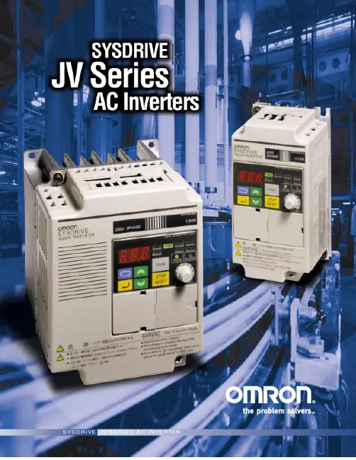
omron_变频器3G3EV手册(E)
- 格式:pdf
- 大小:931.36 KB
- 文档页数:89
USER’S MANUAL SYSDRIVE 3G3EV SERIES(Standard Models)Compact Low-noise InverterThank you for choosing this SYSDRIVE 3G3EV-series product. Proper use and handling of the product will ensure proper product performance, will length product life, and may prevent possible accidents.Please read this manual thoroughly and handle and operate the product with care.NOTICE1.This manual describes the functions of the product and relations with otherproducts. You should assume that anything not described in this manual is not possible.2.Although care has been given in documenting the product, please contactyour OMRON representative if you have any suggestions on improving this manual.3.The product contains potentially dangerous parts under the cover. Do notattempt to open the cover under any circumstances. Doing so may result in injury or death and may damage the product. Never attempt to repair or dis-assemble the product.4.We recommend that you add the following precautions to any instructionmanuals you prepare for the system into which the product is being installed.S Precautions on the dangers of high-voltage equipment.S Precautions on touching the terminals of the product even after power has been turned off. (These terminals are live even with the power turned off.)5.Specifications and functions may be changed without notice in order to im-prove product performance.Items to Check Before UnpackingCheck the following items before removing the product from the package: S Has the correct product been delivered (i.e., the correct model number and specifications)?S Has the product been damaged in shipping?S Are any screws or bolts loose?1-1Items to be Checked when Unpacking1-2. . . . . . . . . . . . . . . . . . . . . . . . . . . . . .. . . . . . . . . . . . . . . . . . . . . . . . . . . . . . . . . . . . . . . . . . . . . . . . . . .1-2Precautions1-3. . . . . . . . . . . . . . . . . . . . . . . . . . . . . . . Chapter 2. Overview2-1 . . . . . . . . . . . . . . . . . . . . . . . . . . . . . . . . . . . . . . . . . . . . . . . . . . . . . .2-1Features2-2. . . . . . . . . . . . . . . . . . . . . . . . . . . . . . . . . . . . . . . . . . . . .2-2Component Names2-4. . . . . . . . . . . . . . . . . . . . . . . . . . . . . . . . . Chapter 3. Design3-13-1Installation3-2. . . . . . . . . . . . . . . . . . . . . . . . . . . . . . . . . . . . . . . . . . . . . . . . . . .. . . . . . . . . . . . . . . . . . . . . . . . . . . . . .3-1-1Outside/Mounting Dimensions3-2. . . . . . . . . . . . . . . . . . . . . . . . . . . . . . . . . . . . .3-1-2Installation Conditions3-5 . . . . . . . . . . . . . . . . . . . . . . . . . . . . . . . . . . . . . . . . . . . . . . . . . . . . . . .3-2Wiring3-7. . . . . . . . . . . . . . . . . . . . . . . . . . . . . . . . . . . . . . . . . .3-2-1Terminal Blocks3-7. . . . . . . . . . . . . . . . . . . . . . . . . . . . .3-2-2Wiring Around the Main Circuit3-113-2-3Wiring Control Circuit Terminals3-18. . . . . . . . . . . . . . . . . . . . . . . . . . . .. . . . . . . . . . . . . . . . . . Chapter 4. Preparing for Operation4-1. . . . . . . . . . . . . . . . . . . . . . . . . . . . . . . . . . . . . . . . . . .4-1Preparation Procedure4-2. . . . . . . . . . . . . . . . . . . . . . . . . . . . . . . . . . . . . . .4-2Using the Digital Operator4-3. . . . . . . . . . . . . . . . . . . . . . .4-2-1Name and Function of Each Component4-3. . . . . . . . . . . . . . . . . . . . . . . . . . . . . . . . . . . . . .4-2-2Outline of Operation4-54-2-3Setting Constants4-8. . . . . . . . . . . . . . . . . . . . . . . . . . . . . . . . . . . . . . . . .. . . . . . . . . . . . . . . . . . . . . . . . . . . . . . . . . . . . . . . . . . . . . . . . . . . . .4-3Test Run4-25. . . . . . . . . . . . . . . . . . . . . . . . . . . . . . . . . . . . . . . . .4-3-1Checking Wiring4-25. . . . . . . . . . . . . .4-3-2Turning Power On and Checking Indicator Display4-25. . . . . . . . . . . . . . . . . . . . . . . . . . . . . . . . . . . . . .4-3-3Initializing Constants4-25. . . . . . . . . . . . . . . . . . . . . . . . . . . . . . . . . . . . . . .4-3-4Setting a V/f Pattern4-254-3-5Setting Rated Motor Amperage4-26. . . . . . . . . . . . . . . . . . . . . . . . . . . . . .. . . . . . . . . . . . . . . . . . . . . . . . . . . . .4-3-6Setting the Reference Frequency4-26. . . . . . . . . . . . . . . .4-3-7Operating the Inverter with the Digital Operator4-26. . . . . . . . . . . . . . . . . . . .4-3-8Checking Output Frequency and Amperage4-26. . . . . . . . . . . . . . . . . . .4-3-9Checking Operation during Reverse Rotation4-26. . . . . . . . . .4-3-10Checking Operation with Mechanical System Connected4-264-3-11Checking Operation Performed by Controller4-26. . . . . . . . . . . . . . . . . . .i5-1Protective and Diagnostic Functions5-2. . . . . . . . . . . . . . . . . . . . . . . . . . . . . . .. . . . . . . . . . . . . . . . . . . . . . . . . . . . . . . . . . . . . . . . . . . . . . .5-2Troubleshooting5-8. . . . . . . . . . . . . . . . . . . . . . . . . . . . . . . . . . . . . .5-2-1Constants Fail to Set5-8. . . . . . . . . . . . . . . . . . . . . . . . . . . . . . . . . . . . .5-2-2Motor Fails to Operate5-8. . . . . . . . . . . . . . . . . . . . . . . .5-2-3Motor Rotates in the Wrong Direction5-9. . . . . . . . . . . . . . . . . . . . . . . . . . . . .5-2-4Motor Deceleration is Too Slow5-105-2-5V ertical-axis Load Drops when Brakes are Applied5-10. . . . . . . . . . . . . .. . . . . . . . . . . . . . . . . . . . . . . . . . . . . . . . . . . . . . . . . . . . .5-2-6Motor Burns5-11. . . . . . . . . . . . . .5-2-7Controller Receives Noise when Inverter is Started5-115-2-8AM Radio Receives Noise when Inverter is Started5-11. . . . . . . . . . . . . .. . . . . .5-2-9Ground Fault Interrupter is Actuated when Inverter is Started5-12. . . . . . . . . . . . . . . . . . . . . . . . . . . .5-2-10Mechanical System Makes Noise5-12. . . . . . . . . . . . . . . . . . . . .5-2-11Motor Does Not Operate with EF Warning5-12. . . . . . . . . . . . . . . . . . . . . . . . . . . . . . . . . . . . . .5-3Maintenance and Inspection5-13. . . . . . . . . . . . . . . . . . . . . . . . . . .Chapter 6. Specifications6-1. . . . . . . . . . . . . . . . . . . . . . . . . . . . . . . . . . . . . .6-1Specifications of Main Unit6-2. . . . . . . . . . . . . . . . . . . . . . . . . . . . .Chapter 7. Appendix A7-1. . . . . . . . . . . . . . . . . . . . . . . . . . . . . . . . .7-1Notes on Using Inverter for Motor7-2. . . . . . . . . . . . . . . . . . . . . . . . . . .7-2Frequency Reference by Amperage Input7-4. . . . . . . . . . . . . . . . . . . . . . . . . . . . . . . . . . . . . . . . . .7-3List of Product Models7-7iiChapter 1Getting Started1-1Items to be Checked when Unpacking1-2Precautions1-21-1Items to be Checked when Unpacking H Checking the ProductOn delivery, always check that the delivered product is the SYSDRIVE 3G3EV Inverter that you ordered.Should you find any problems with the product, immediately contact your nearest local sales representative.DChecking the NameplateInverter modelInput specifications Output specificationsD Checking the ModelSpecial SpecificationSpecificationsMaximum applicable motor capacityVoltage classInstallation typeSeries name: 3G3EV SeriesSpecificationsMaximum Applicable Motor CapacityNote The figures in parentheses indi-cate capacities for 400-VAC classmodels.1-3Voltage ClassInstallation Type/OptionSpecial SpecificationD Checking for DamageCheck the overall appearance and check for damage or scratches resulting from trans-portation.H Checking Accessories Note that this manual is the only accessory provided with the 3G3EV (Standard Model).Set screws and other necessary parts must be prepared by customers.1-2PrecautionsTo ensure safe operation of the 3G3EV, note the following items:H Always Hold the Heat Sink During Removal.When moving the 3G3EV, always hold the heat sink (aluminum portion on the rear of the Unit).Heat sinkH Watch Out for Residual Voltage On Charged PortionsAfter the power is turned off, residual voltage remains in the capacitor inside the Inverter. Therefore, touching terminals immediately after turning the power off may cause an electrical shock.If an inspection or some other task is to be performed, always wait at least one minute from the time all indicators on the front panel go off.(Note that this warning is applicable whenever you perform any task after turning the main circuit off.)H Do Not Remove the Digital Operator When the Main Circuit is Still On.Always turn the main circuit off before removing the digital operator.Removing the digital operator with the main circuit ON may cause an electrical shock and damage the equipment.H Do Not Modify Wiring or Check Signals When the Main Circuit is On.Always turn the main circuit off before modifying wiring or checking signals. Touching terminals while the main circuit is on may cause an electrical shock and dam-age the equipment.H Do Not Conduct a Dielectric Strength Test.Because the 3G3EV Inverter is an electronic control unit using semiconductor, never conduct a dielectric strength test or an insulation resistance test for the control circuit.H Modify Constant Settings Correctly.Always modify the constant settings according to the procedures described in this manual.1-4Chapter 2Overview2-1Features2-2Component Names2-22-1Features H Easy to UseD Basic Constants Displayed On IndicatorsConstants for basic operations such as frequency setting and acceleration/deceleration time setting are displayed on dedicated indicators. Therefore, constant numbers can be confirmed easily.D Minimum Constant Setting ItemsConstant setting items have been minimized to enable even first-time users to set constants easily.H Easy to InstallD Very Small and LightweightThe 3G3EV Inverter is approximately half the size of our Low-noise General-purpose Inverters in terms of volume and weight percentage. This improves space efficiency and operating efficiency (including easier removal).D Optional DIN TrackAn optional DIN track is available. This DIN track enables the user to mount the 3G3EV Inverter on the DIN track with a one-touch operation.OverviewChapter 2Overview Chapter 2 H Easy to WireD Easy Wiring without Having to Open the Front CoverThis Inverter can be wired just by opening the terminal block cover.D Separate Input and Output Terminal BlocksPower input terminals are located in the upper section, while motor output terminals are in the lower section. In this way, the input and output terminal blocks are separated ac-cording to the contactors, so incorrect wiring can be prevented.D Soldering No Longer NecessaryNo connector means no soldering.H Easy to OperateD Switching the Operation Mode with a One-touch OperationFor example, after a test run is performed using the Digital Operator, it can be easily switched to a production run using control terminals with a one-touch operation.D Checking a Test Run with Various MonitorsOutput frequency, output current, and the direction of motor rotation appear in the dis-play section of the Digital Operator, so the mechanical system can be easily monitored during a test run.H Low NoiseAn insulated gate bipolar transistor (IGBT) power element has been adopted to elimi-nate metallic noise.H High-torque Operation Even in Low Speed RangeA torque rate of 150% can be achieved even in a low speed range where output frequen-cy is only 3 Hz. Thus, acceleration time can be reduced.H Various Input Power SuppliesA 400-VAC-class Inverter has been newly added to the 3G3EV Series to cope with vari-ous power supplies.•Three-phase 200-VAC input:0.1 to 1.5 kW•Single/Three-phase 200-VAC input:0.1 to 1.5 kW•Three-phase 400-VAC input:0.2 to 1.5 kW2-32-42-2Component NamesH Main UnitMain Circuit Terminals (Input)Power input terminals Braking resistor connection terminalsRun indicator Alarm indicatorControl circuit terminals(output)Ground terminalMain Circuit Terminals (Output)Motor output terminalsDigital OperatorControl circuitterminals (input)MAMBMCSF SR S1SC FS FR FCH Digital OperatorDisplaysectionOperationkeysMode Key Increment KeyRUN KeyData display sectionMonitor item indicatorsIn-service item indicators (green indicators)These items can be monitored or set evenduring operation.Stopped item indicators (red indicators)These items can be set only when theInverter is stopped.Constant item indicatorsEnter KeyDecrement KeySTOP/RESET Key2-5Chapter 3Design3-1Installation3-2Wiring3-1Installation3-1-1Outside/Mounting DimensionsNote All dimensions are in millimeters.H3G3EV-A2001(-j) to 3G3EV-A2004(-j) (0.1 to 0.4 kW):Three-phase 200-VAC InputH3G3EV-AB001(-j) to 3G3EV-AB002(-j) (0.1 to 0.2 kW): Single/Three-phase 200-VAC Input4.5 dia.Note1.For the 3G3EV-A2001(-j), 3G3EV-A2002(-j), and 3G3EV-AB001(-j), a U-shaped notch (4.5 mm wide) is provided instead of the upper mounting hole (4.5 mm in diameter).Note2.Install the Inverter with two M4 bolts.3-2D Three-phase 200-VAC Input Model3-3H3G3EV-A2007(-j) to 3G3EV-A2015(-j) (0.75 to 1.5 kW): Three-phase 200-VAC Input3G3EV-AB004(-j) to 3G3EV-AB015(-j) (0.4 to 1.5 kW): Single/Three-phase 200-VAC Input3G3EV-A4002(-j) to 3G3EV-A4015(-j) (0.2 to 1.5 kW): Three-phase 400-VAC InputTwo, 4.5 dia.Note Install the Inverter with four M4 bolts.3-43-5D Three-phase 400-VAC Input Model3-1-2Installation ConditionsH Installation Site•Install the Inverter under the following conditions:Ambient temperature for operation: –10°C to 50°C Humidity: 90% RH or less (non-condensing)•Install the Inverter in a clean location free from oil mist and dust. Alternatively, install it in a totally enclosed panel that is completely shielded from suspended dust.•When installing or operating the Inverter, always take special care so that metal pow-der, oil, water, or other foreign matter do not get in the Inverter.•Do not install the Inverter on inflammables such as wood.H Direction of Installation•Install the Inverter on a vertical surface so that the characters on the nameplate are oriented upward.H Installation Space•When installing the Inverter, always provide the following installation space to allow normal heat dissipation from the Inverter:W= 30 mm min.100 mm min.100 mm min.AirSideAirI n v e r t e rI n v e r t e rI n v e r t e rH Ambient Temperature Control•To enhance operation reliability, the Inverter should be installed in an environment free from extreme temperature rises.•If the Inverter is installed in an enclosed environment such as a box, use a cooling fan or air conditioner to maintain the internal air temperature below 50°C.•The surface temperature of the Inverter may reach 30°C higher than the ambient tem-perature. Therefore, keep all thermally susceptible devices and wires away from the Inverter.H Protecting the Inverter from Foreign Matter during Installation •Place a cover over the Inverter to shield it from metal powder produced by drilling dur-ing installation.(Upon completion of installation, always remove the cover from the Inverter. Other-wise, ventilation will be affected, causing the invert to overheat.)3-63-73-2Wiring3-2-1Terminal BlocksH Name of Each Terminal BlockMain Circuit Terminals (Input)Power input terminalsBraking resistorconnection terminalsControl circuit terminals (output)Ground terminal Main circuit terminals (output)Motor Output Terminals (Output)Control circuit terminals (input)MAMBMCSF SR S1SC FS FRFCH Main Circuit TerminalsNote Before shipping, a resin plate is attached to each braking resistor connection ter-minal to prevent incorrect wiring.When connecting a braking resistor, always remove the resin plates with a pair of long-nose pliers.Terminal block screw (M3.5)Crimpterminal6.2 mm max.H Control Circuit TerminalsD Input Terminals (On Right-hand Side)No external power supply is required because a built-in power supply is provided.24 VDC, 8 mA(See note3)(See note 3)Input impedanceIn ut im edanceNote1.Constant No. 06 (n06) is used to set this function. This constant is factory-set to “fault reset.”Note2.FR can be switched to an amperage input terminal (4 to 20 mA) by setting the internal DIP switch and constant No. 02 (operation mode selection). For details, refer to 7-2 Frequency Reference by Amperage Input.Note3.The circuit for a 400-VAC-class Inverter is as shown below.SFSRS1 to S3SCD Output Terminals (On Left-hand Side)30 VDC250 VACNote Constant No. 09 (n09) is used to set the function. This constant is factory set to “operation in progress.”H Standard Connection DiagramMolded-case circuitbreaker (MCCB) Forward/StopReverse/StopMulti-function input Sequence input common Frequencyreferencerheostat(2 kΩ,1/4 W min.)Braking resistor (option)Multi-function contact output(Contact a)(Contact b)CommonL1N/L2L3Power supply:Three-phase, 200 to 230 VAC, 50/60 HzThree-phase, 380 to 460 VAC, 50/60 HzNote1.If a 3G3EV-AB jjj is used in single-phase input mode, single-phase 200 to 240 VAC power with a frequency of 50/60 Hz must be input between terminals R and S.Note2.For the 3-wire sequence, refer to the wiring on page 4-12.Note3.The input sequence power is built in.3-2-2Wiring Around the Main CircuitSystem reliability and noise resistance are affected by the wiring methodused. Therefore, always follow the instructions given below when connect-ing the Inverter to peripheral devices and other parts.H Wire Size and Molded-Case Circuit Breaker to be UsedFor the main circuit and ground, always use 600-V polyvinyl chloride (PVC) cables. If the cable is long and may cause voltage drops, increase the wire size according to the cable length.Note Tighten the M3.5 terminal screw to the torque of 0.8 N S m.Determining the Wire SizeDetermine the wire size for the main circuit so that line voltage drop is within 2% of the rated voltage.Line voltage drop V D is calculated as follows:V D (V) = p3 x wire resistance (Ω/km) x wire length (m) x amperage (A) x 10–3H Wiring on the Input Side of Main CircuitD Installing a Molded-case Circuit BreakerAlways connect the power input terminals (R, S, and T) and power supply via a molded-case circuit breaker. Power must be supplied instantaneously. Unstable power startup will not start the Inverter.D Installing a Ground Fault InterrupterIf a ground fault interrupter is to be connected to the wire on the primary side (R, S, and T) of the main circuit, use either of the following interrupters to prevent malfunctions:•Ground fault interrupter with a sensitivity amperage of 200 mA or more and with an operating time of 0.1 second or more•Ground fault interrupter with high-frequency countermeasures (for Inverter)D Installing a Magnetic ContactorThis Inverter can be used without a magnetic contactor (MC) on the power supply side. If the power supply for the main circuit is to be shut off because of the sequence, a mag-netic contactor can be used instead of a molded-case circuit breaker.However, when a magnetic contactor is installed on the primary side of the main circuit to forcibly stop a load, note that regenerative braking does not work and the load coasts to a stop.•A load can be started and stopped by opening and closing the magnetic contactor on the primary side. Note, however, that frequently opening and closing the magnetic contactor may cause the Inverter to break down.•When the Inverter is operated with a Digital Operator, automatic operation cannot be performed after recovery from a power interruption.D Connecting Input Power Supply to the Terminal BlockBecause the phase sequence of input power supply is irrelevant to the phase sequence (R, S, T) of the terminal block, input power supply can be connected to any terminal on the terminal block.D Installing an AC ReactorIf the Inverter is connected to a large-capacity power transformer (600 kW or more) or the phase advance capacitor is switched, an excessive peak current may flow through the input power circuit, causing the converter unit to break down. T o prevent this, install an optional AC reactor on the input side of the Inverter. This also improves the power factor on the power supply side.D Installing a Surge AbsorberAlways use a surge absorber or diode for the inductive loads to be connected to the Inverter. These inductive loads include magnetic contactors, electromagnetic relays, solenoid valves, solenoids, and magnetic brakes.D Wiring of Braking Resistor/Braking Resistor UnitWhen using an Inverter for loads with a large inertia or for vertical axis loads, regenera-tive energy will be fed back.If the regenerative energy exceeds the Inverter capacity, overvoltage will be detected in the main circuit. In such a case, use a Braking Resistor or Braking Resistor Unit. Note Be sure to create a sequence that will turn OFF the Inverter power supply when resistor overheating occurs. When using a Braking Resistor, be sure to install a thermal relay to detect resistor overheating. When using a Braking Resistor Unit, use an error output contact. Otherwise, a fire may occur.Note Do not use a Resistor whose resistance is below the minimum connected resis-tance. Otherwise, the Inverter will be damaged.D Installing a Noise Filter on the Power Supply SideInstall a noise filter to eliminate noise transmitted between the power line and the Inverter.Wiring Example 13G3IV-PHF3G3EVPower supplyNoise filterSYSMAC,etc.Other controllersNote Use a special-purpose noise filter for Inverters.Wiring Example 23G3EVGeneral-purpose noise filterPower supplySYSMAC,etc.Other controllers3G3EVPower supplyGeneral-purpose noise filterSYSMAC,etc.Other controllersNote Do not use a general-purpose noise filter.H Wiring on the Output Side of Main CircuitD Connecting the Terminal Block to the LoadConnect output terminals U, V, and W to motor lead wires U, V, and W, respectively.D Never Connect Power Supply to Output TerminalsCaution Never connect a power supply to output terminals U, V, and W.If voltage is applied to the output terminals, the internal mechanism of the Inverter will be damaged.D Never Short or Ground the Output TerminalsCaution If the output terminals are touched with bare hands or the output wires comeinto contact with the Inverter casing, an electric shock or grounding will occur.This is extremely hazardous. Also, be careful not to short the output wires.D Do Not Use a Phase Advance Capacitor or Noise FilterNever connect a phase advance capacitor or LC/RC noise filter to the output circuit. Do-ing so may result in damage to the Inverter or cause other parts to burn.D Do Not Use an Electromagnetic SwitchDo not connect an electromagnetic switch or magnetic contactor to the output circuit. If a load is connected to the Inverter during operation, an inrush current will actuate the overcurrent protective circuit in the Inverter.D Installing a Thermal RelayThis Inverter has an electronic thermal protection function to protect the motor from overheating. If, however, more than one motor is operated with one Inverter or a multi-polar motor is used, always install a thermal relay (THR) between the Inverter and the motor and set to “0.0” (no thermal protection) for constant No. 31 (“THR” indicator).In this case, program the sequence so that the magnetic contactor on the input side of the main circuit is turned off by the contact of the thermal relay.D Installing a Noise Filter on the Output SideConnect a noise filter to the output side of the Inverter to reduce radio noise and induc-tion noise.3G3EV3G3IV-PLFPower supplyNoise filterSignal lineControllerInduction noise Radio noise AM radioInduction Noise:Electromagnetic induction generates noise on the signal line, causingthe controller to malfunction.Radio Noise:Electromagnetic waves from the Inverter and cables cause thebroadcasting radio receiver to make noise.D How to Prevent Induction NoiseAs described above, a noise filter can be used to prevent induction noise from being generated on the output side. Alternatively, cables can be routed through a grounded metal pipe to prevent induction noise. Keeping the metal pipe at least 30 cm away from the signal line considerably reduces induction noise.3G3EV30 cm min.MCCBMetal pipePower supplySignal lineControllerD How to Prevent Radio NoiseRadio noise is generated from the Inverter as well as the input and output lines. To re-duce radio noise, install noise filters on both input and output sides, and also install the Inverter in a totally enclosed steel box.The cable between the Inverter and the motor should be as short as possible.3G3EVPower supplySteel boxNoise filterNoise filterMetal pipeD Cable Length between Inverter and MotorIf the cable between the Inverter and the motor is long, the high-frequency leakage cur-rent will increase, causing the Inverter output current to increase as well. This may affect peripheral devices. T o prevent this, adjust the carrier frequency (set in n37) as shown in the table below.H Ground Wiring•Always use a ground terminal with the following ground resistance.200-VAC Class:100 Ω or less400-VAC Class:10 Ω or less•For 400-VAC-class models that conform to EC Directives, also connect to the neutral of the power supply.•Do not share the ground wire with other devices such as a welder or power tool.•Always use a ground wire that complies with technical standards on electrical equip-ment. Route the ground wire so that the total length is as short as possible.•When using more than one Inverter, be careful not to loop the ground wire.3-2-3Wiring Control Circuit TerminalsThe control signal line must be 50 m or less and must be separated fromthe power line. If frequency references are input externally, use a twisted-pair shielded line.H Wiring Sequence Input/Output TerminalsWire the sequence input terminals (SF, SR, S1, and SC) and the multi-function contact output terminals (MA, MB, and MC) as described below.D Wiring Method•Wire each terminal as follows:a)Loosen the terminal screw with a thin-slotted screwdriver.b)Insert the wire from underneath the terminal block.c)Tighten the terminal screw firmly.•Always separate the control signal line from the main circuit cables and other power cables.Thin-slotted screwdriverLength of stripped portion: Approx. 5.5 mmWireControl circuitterminal blockDo not solder this portion. (Otherwise, faulty contact may result.)H Wiring Frequency Reference Input TerminalsIf frequency references are input using a D/A unit (digital-to-analog converter) or exter-nal power supply, wire the frequency reference input terminals (FR and FC) as de-scribed below.3-18。