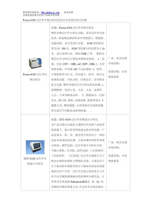
国产思博CNS-6000B近红外谷物分析仪
- 格式:pdf
- 大小:3.38 MB
- 文档页数:59
近红外谷物分析仪安全操作及保养规程近红外谷物分析仪广泛应用于谷物、油料、饲料等领域中的定量分析,但在使用过程中,必须严格按照操作规程进行,方可保证分析结果的精确性和设备的稳定性。
本文将从仪器的安全使用和保养方面介绍谷物分析仪的操作规范和注意事项。
1. 安全操作规程1.1 电源谷物分析仪的电源应符合设备的要求,不得与其他设备的电源混接,开启电源之前,应检查电源线路是否牢固,不得破损或过度折曲。
1.2 设备操作1.开机前应先检查设备的各个部位是否在正常工作状态,确保设备不受到任何损坏或缺陷。
2.操作人员必须保证手部干燥、清洁,防止电击或触电事故的发生。
3.在操作谷物分析仪时必须按照正确的操作顺序进行,不得随意拆卸、更换或调整设备的任何部分。
4.设备必须在正常工作环境中使用,不得受到任何外界干扰或冲击,以免影响设备的稳定性和精确性。
5.操作人员必须认真阅读设备的使用手册和操作指南,熟练掌握设备的操作要点和注意事项。
1.3 样品准备1.样品应按照样品准备方法进行准备,并严格按照使用手册中的要求进行存储。
2.样品的处理过程中,操作人员必须严格按照操作规程进行,以免影响到样品的稳定性和精确性。
3.使用样品过程中,操作人员应保证实验室的卫生和清洁,以免影响谷物分析仪分析结果的精确性和准确性。
1.4 紧急情况处理在设备操作过程中,如遇到突发状况或故障,应立即切断电源并通知相关人员及负责人,以免造成不必要的损失和安全事故。
2. 设备的保养规程2.1 定期保养1.样品室应每日进行清洁,同时检查设备的排风系统是否正常工作。
2.设备的光学系统应每季度进行清洁和校正,保证设备的精确性和稳定性。
3.设备的样品接口和光路应每6个月清洗一次,以免影响谷物分析仪的准确性和稳定性。
2.2 维护保养1.设备的电子元件应受到积极的维护和保养,在长期使用过程中应进行定期的维护和更换。
2.定期更换设备的耗材和易耗品,如纸张、滤纸、流量计等。
大豆浓缩蛋白中蛋白质和水分的检测引言:在豆类加工工业中,近红外光谱(NIR)是一种公认的品质控制工具。
常规NIR分析检验豆粕、豆壳和豆的“白片”,可以监测磨粉和榨油的过程。
另外一种大豆加工企业感兴趣的豆类产品是大豆浓缩蛋白(SPC)。
除去可溶性碳水化合物时,将大豆蛋白固定在脱脂豆粕上,制成SPC。
产品的蛋白质含量大约为70%。
利用此工艺,1000kg的脱脂豆饼可以产生约750kg的SPC。
SPC被用于制作焙烤食品、谷物早餐和一些肉制品。
SPC对肉和家禽的功能是提高保留的水分和脂肪,也可以通过添加更多的蛋白质增加其营养价值。
SPC易消化,非常适合儿童、孕妇和老人。
也可以用于宠物食品和作为小牛和猪的代乳食品。
本研究的目的是开发NIR在分析大豆浓缩蛋白中蛋白质和水分的应用。
这被大豆加工企业用于监测碳水化合物的分离和蛋白质浓缩。
SPC的干基蛋白含量不能低于65%。
大豆加工企业已经有能力使用NIR监控SPC的生产,保证产品的品质。
试验设计:该实验在美国一家主要的大豆加工公司协助下进行。
SPC样品由工作人员收集,带到湿化学室分析。
每一个样品都使用带1mm屏幕的Udy Cyclone粉碎机反复研磨。
实验室收集和分析了636个样品,蛋白含量使用杜马斯燃烧法测定。
水分含量使用快速烘箱水分测定法,实验室收集和分析197个样品。
为了建立标准,收集近红外光谱范围,每一个样品都放到金属杯里,使用Unity Scientific SpectraStar 2400进行分析。
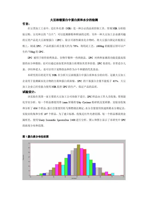
图1和图2显示了本研究中SPC 的浓度分布和范围。
图1.蛋白质分布柱状图图2.水分分布柱状图图3.大豆浓缩蛋白的近红外光谱校准结果:使用Unity CalStar校准软件计算蛋白质和水分的偏最小二乘法(PLS)校准结果。
图4.蛋白质校准的近红外和实验室结果散点图图5.水分校准的近红外和实验室结果散点图结论:Unity SpectraStar 2400近红外分析仪可以计算大豆浓缩蛋白中的蛋白质和水分。
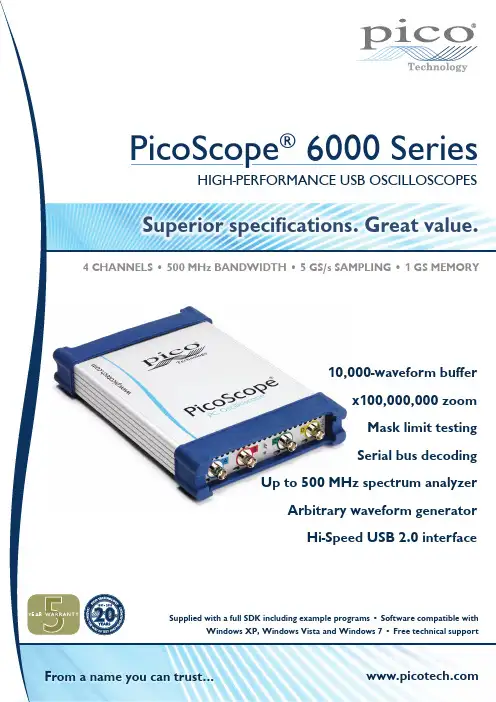
Superior specifications. Great value.Supplied with a full SDK including example programs Windows XP, Windows Vista and Windows 7 From a name you can trust...4 Channels • 500 mh z bandwidth • 5 gs/s sampling • 1 gs memory10,000-waveform bufferx100,000,000 zoom mask limit testing Serial bus decodingUp to 500 mhz spectrum analyzerArbitrary waveform generator Hi-Speed USB 2.0 interfaceArbitrary waveform and function generatorGenerate standard waveforms from DC to 20 MHz (all models) or define your own using the power of the built-in 12-bit, 200 MS/s arbitrary waveform generator (B models only). You can import arbitrary waveforms from data files or draw them using the built-in AWG editor.Spectrum analyzerWith the click of a button, you can open a new window to display a spectrum plot of selected channels. The spectrum analyzer allowsColor persistence modesSee old and new data superimposed, with new data in a brightercolor or shade. This makes it easy to see glitches and dropouts and to estimate their relative frequency. Choose between analog persistence and digital color, or create a custom display mode.High-speed data acquisitionThe drivers and software development kit supplied allow you towrite your own software or interface to popular third-party software packages. If the 1 gigasample record length of the PicoScope 6404B Spectrum analyzerArbitrary waveform generatorPicoScope performance and reliabilityWith 20 years’ experience in the test and measurement industry, we know what’s important in a new oscilloscope. The PicoScope 6000 Series scopes have the best bandwidth, sampling rate and memory depth of any USB oscilloscopes. These features are backed up by advanced software developed with the help of feedback from our customers.High bandwidth, high sampling rateWith a 250 MHz to 500 MHz analog bandwidth complemented by a real-time sampling rate of 5 GS/s, the PicoScope 6000 Series scopes can display single-shot pulses with 200 ps time resolution. ETS mode boosts the maximum sampling rate to 50 GS/s, giving higher timing resolution for repetitive signals.Huge buffer memoryThe PicoScope 6000 Series gives you the deepest buffer memory available as standard on any oscilloscope. Other oscilloscopes have high maximum sampling rates, but without deep memory they cannot sustain these rates on long timebases. The 1-gigasample buffer on the PicoScope 6404B allows it to capture at 5 GS/s down to 20 ms/div for a total duration of 200 ms. To help manage all this two zoom methods. There are zoom buttons as well as an overview window that lets you zoom and reposition the display by simply dragging with the mouse.Advanced triggersAs well as the standard range of triggers found on most oscilloscopes, the PicoScope 6000 Series has a built-in set of advanced triggers to help you capture the data you need.All triggering is digital, resulting in high threshold resolution and excellent waveform stability.Custom probe settingsThe custom probes feature allows you to correct for gain, attenuation, offsets and nonlinearities in special probes, or toconvert to different units of measurement. Definitions for standard Pico-supplied probes are built in, but you can also save your own definitions to disk for later use.Rapid triggeringThe PicoScope 6000 Series contains special triggering hardware to minimise the time between captures. This enables you to collect waveforms at intervals of 1 μs or less when using a short timebase, improving your chances of spotting an infrequent glitch.Deep memory allows you to zoom in... and in... and in6000 Color persistence modesSerial data decoding:CAN • LIN • UART • SPI • I 2CThe PicoScope 6000 Series oscilloscopes are well-suited to serial decoding, with a deep memory buffer that allows them to collect long, uninterrupted sequences of data. This allows the capture of thousands of frames or packets of data over several seconds. The scopes can decode up to four buses simultaneously with independent protocol selection for each input channel.PicoScope displays the decoded data in the format of your choice: “in view”, “in window”, or both at once.“In view” format shows the decoded data beneath the waveformon a common time axis, with error frames marked in red. You can zoom in on these frames to look for noise or distortion on the waveform.“In window” format shows a list of the decoded frames, includingthe data and all flags and identifiers. You can set up filteringconditions to display only the frames you are interested in, search for frames with specified properties, or define a start pattern that the program will wait for before it lists the data.Mask limit testingThis feature is designed for production and debugging environments.Capture a signal from a known working system, and PicoScope will draw a mask around it with your specified tolerance. Connect the system under test, and PicoScope will highlight any parts of thewaveform that fall outside the mask area. The highlighted details persist on the display, allowing the scope to catch intermittent glitches while you work on something else. The measurements window counts the number of failures, and can display other measurements and statistics at the same time.The numerical and graphical mask editors (both shown above) can be used separately or in combination, allowing you to enter accurate mask specifications or modify existing masks. You can import and export masks as files.Digital low-pass filteringEach input channel has its owndigital low-pass filter withindependently adjustable cut-off frequency from 1 Hz to the full Accessories includedInstruction manualSolid tip 0.5 mmCoding rings, 3 x 4 colors Ground lead 15 cm TA133• Instruction manual • Solid tip 0.5 mm• Coding rings, 3 x 4 colors • Ground lead 15 cm Serial data decodingMask limit testingmovable axes: The vertical axes can be dragged up and down. This feature is particularly useful when one waveform is obscuring another. There’s alsoan Auto Arrange Axes command.Automatic measurements: Display calculated measurements fortroubleshooting and analysis. You can add as many measurements as youneed on each view. Each measurement includes statistical parametersshowing its variability.Built-in measurements:AC RMS, True RMS, DC Average, Cycle Time,Frequency, Duty Cycle, Falling Rate, Fall Time, Rising Rate, Rise Time,High Pulse Width, Low Pulse Width, Maximum, Minimum, Peak to Peakmask limit testing:Automatically generate atest mask from a waveformor draw one by hand.PicoScope highlights anyparts of the waveform thatfall outside the mask andshows error statistics.PicoScopeChannels (vertical)6402A 6402B 6403A 6403B 6404A 6404BNumber of channels 4 (BNC connectors)Bandwidth (-3 dB)250 MHz (TA150 probes/50 Ω)200 MHz (±50 mV range)350 MHz (TA150 probes/50 Ω)250 MHz (±50 mV range)500 MHz (TA133 probes/50 Ω)Bandwidth limiterSwitchable, 20 MHz Switchable, 20 MHz Switchable, 25 MHzRise time (10% to 90%, calculated)1.4 ns 1.0 ns 0.7 nsVoltage ranges±50 mV to ±20 V (up to ±5 V when 50 Ω input selected)Sensitivity 10 mV/div to 4 V/div at x1 zoom Input coupling AC or DC (1 MΩ) or DC (50 Ω)Input impedance1 MΩ || 15 pF, or 50 Ω 1 MΩ || 10 pF, or 50 ΩInput offset (position) adjustmentInput range Offset range 50 to 200 mV ±0.5 V 500 mV ±2.5 V 1 V ±2.5 V 2 V ±2.5 V 5 V ±20 V (50 Ω: ±0.5 V)10 V ±20 V 20 V ±20 V Input range Offset range 50 to 200 mV ±2 V 500 mV ±10 V (50 Ω: ±5 V)1 V ±10 V (50 Ω: ±4.5 V)2 V ±10 V (50 Ω: ±3.5 V)5 V ±35 V (50 Ω: ±0.5 V)10 V ±30 V 20 V ±20 VDC accuracy3%Overload protection±100 V to ground (1 MΩ inputs), 5.5 V RMS (50 Ω inputs)Timebase (horizontal)Timebases (real-time sampling)10 ns/div to 1000 s/div Timebases (equivalent-time sampling/ETS)1ns/div to 1000 s/divTimebase accuracy5 ppmAcquisitionADC resolution8 bits (up to 12 bits in resolution enhancement mode)Maximum real-time sampling rate5 GS/s (one channel enabled), 2.5 GS/s (two channels enabled), 1.25 GS/s (three or four channels enabled)Maximum equivalent-time sampling (ETS) rate 50 GS/s (any number of channels)Buffer size (shared between active channels)128 MS 256 MS 256 MS 512 MS 512 MS 1 GS Maximum buffer segments 125 000250 000250 000500 000500 000 1 000 000Maximum streaming data rate1 MS/s in PicoScope software. >10 MS/s using supplied SDK (PC-dependent)TriggerBasic triggers Rising, fallingAdvanced triggers Edge, Pulse width, Window, Window pulse width, Dropout, Window dropout, Level, Interval, Logic level, Runt pulseTrigger modes None, Single, Repeat, Auto, Rapid, ETS Maximum trigger rate Up to 10,000 waveforms in a 10 ms burstTrigger timing resolution1 sample period Trigger sources Channels A to D, AUXTrigger level Adjustable over whole of selected voltage rangeRe-arm timeLess than 1 μs on fastest timebaseMaximum pre-trigger capture 100% of capture size Maximum post-trigger delay4 billion samplesAUX inputExternal clock inputReference frequency 5 MHz to 25 MHzInput type50 Ω, BNC, ±1 V threshold adjustment range, ±5 V protection range, DC coupled Function generator and arbitrary waveform generator (AWG)Function generator frequency range DC to 20 MHzFunction generator waveforms (A models)Sine, square, triangle, DCFunction generator waveforms (B models)As A models plus ramp, sin (x)/x, Gaussian, half-sine, white noise, PRBSDAC resolution / DC accuracy12 bits / 1%Amplitude range ±250 mV to ±2 VOffset adjustment ±1 V (max. combined output ±2.5 V)Output impedance 50 ΩAWG buffer size N/A 16 kS N/A 16 kS N/A 16 kS AWG sample rateN/A 200 MS/s N/A 200 MS/s N/A200 MS/sProbe calibration outputSignal output type1 kHz square wave,2 V pk-pk, 600 ΩSpectrum analyzerFrequency range DC to 250 MHzDC to 350 MHz DC to 500 MHzDisplay modes Magnitude, average, peak holdWindowing functions Rectangular, Gaussian, triangular, Blackman, Blackman-Harris, Hamming, Hann, flat-topNumber of FFT pointsSelectable power of 2 from 27 to 220Math channelsFunctions −x, x+y, x−y, x*y, x/y, x^y, sqrt, exp, ln, log, abs, norm, sign, sin, cos, tan,arcsin, arccos, arctan, sinh, cosh, tanh, freq, derivative, integral, min, max, average, peakOperandsInput channels A to D, reference waveforms, time, πSerial bus decodingBaud rate10 kb/s to 1 Mb/s, auto-detect with manual overrideThreshold voltageAuto or manualData formatsCAN, LIN, I 2C, UART/RS-232, SPIMask limit testingStatisticsPass/fail, failure count, total count DisplayInterpolation Linear or sin (x)/xPersistence modesDigital color, analog intensity, custom, or noneGeneralDimensions (including connectors and end caps)255 x 170 x 40 mm (approx. 10.0” x 6.7” x 1.6”) 280 x 170 x 40 mm (approx. 11.0” x 6.7” x 1.6”)Weight1 kg (approx.2 lb3 oz) 1.3 kg (approx. 2 lb 14 oz)Operating temperature range0 °C to 40 °C (20 °C to 30 °C for stated accuracy)Compliance EU: EMC, LVD, RoHS, WEEE. USA: FCC Part 15 Class APC connection USB 2.0 (USB 1.1 compatible)Power supplyAC adapter and cable (cord) suppliedLanguages supportedSimplified Chinese, Traditional Chinese, Czech, Danish, Dutch, English, Finnish, French, German, Greek, Hungarian, Italian, Japanese, Norwegian, Polish, Portuguese, Romanian, Spanish, Swedish, TurkishP i c o S c o p e 6000 S e r i e s P C O s c i l l o s c o p e sSpecificationsPico Technology, James House, Colmworth Business Park, St. Neots, Cambridgeshire, PE19 8YP, United Kingdom ☎ +44 (0) 1480 396 395 +44 (0) 1480 396 296✉******************* Prices are correct at the time of publication. Please contact Pico Technology for the latest prices before ordering. Errors and omissions excepted. Windows is a registered trademark of Microsoft Corporation in the United States and other countries. Pico Technology, PicoScope and PicoLog are internationally registered trade marks of Pico Technology Ltd..Ordering informationDescriptionPicoScope 6402A 250 MHz Oscilloscope with probesPicoScope 6402B 250 MHz Oscilloscope with AWG and probes PicoScope 6403A 350 MHz Oscilloscope with probesPicoScope 6403B 350 MHz Oscilloscope with AWG and probes PicoScope 6404A 500 MHz Oscilloscope with probesPicoScope 6404B 500 MHz Oscilloscope with AWG and probes Replacement x10 probe for PicoScope 6402A/B & 6403A/B Replacement x10 probe for PicoScope 6404A/BHave you seen the PicoScope 6407 Digitizer?The PicoScope 6407 Digitizer has four 1 GHz inputs and a maximum sampling rate of 5 GS/s. See for more information.Product pack contents• PicoScope 6000 Series oscilloscope • Four factory-compensated probes • USB cable• Universal mains (AC) power supply • Mains lead (power cord)• Installation Guide• Software and Reference CD • Carrying caseMM023-7. Copyright © 2011-2012 Pico Technology Ltd. All rights reserved.。
APS-6000B全自动视野计临床应用【中图分类号】r473.74 【文献标识码】b 【文章编号】1672-3783(2011)11-0242-01【摘要】目的:aps—6000b全自动视野计检测视野缺损准确性。
方法:随机取250例双眼病人(500只眼),首先用传统goldmann 手动视野计检查,再用aps—6000b自动视野计检查。
结果:aps—6000b全自动视野计与传统的goldmann手动视野计检查准确率明显差异p<0.05,检测需要的时间明显差异p<0.05。
结论:aps—6000b 全自动视野计准确率高,速度快,提高青光眼可疑青光眼、神经系统疾病、视网膜疾病诊断率。
【关键词】aps—6000b; 全自动视野计;临床应用随着眼科学和视觉生理学不断发展,作为视觉检查重要方法之一,传统的goldmann手动视野计不足以满足其发展。
aps—6000b 全自动视野计系在国内外自动视野计基础上研制新一代自动视野计,它具有两种颜色检测光源,六种检查方法和灵活组成多种检测范围,检查结果自动归类存档,可打印成数字、黑白灰阶图、彩色图、任意剖面图、标准图、三维立体图,较好的做到了功能全、精确度高、科学实用准确、跟踪随访方便、临床参与价值高。
我院2001年6月引进一台aps—6000b全自动视野计到2011年9月共检测病人1968例,现报告如下:1 资料与方法1.1 一般资料检测1968例病人(共3300眼)其中男 915例,女 1053例;单眼636例,双眼 1332例;年龄最大83岁,最小7岁;青光眼及可疑青光眼945例,神经系统疾病 314例,视网膜疾病 553例,其他156例。
随机挑选250例双眼病人(500只眼),进行传统的goldmann手动视野计和aps—6000b全自动视野计两种方法对比检查。
1.2 检查前准备视野检查须在暗室进行,以排除外界光线干扰,病人检查前先检查视力、眼压、房角、眼压描计、裂隙灯检查,屈光不正需矫正视力。
谷物近红外分析仪安全操作及保养规程前言谷物近红外分析仪是一种用于分析谷物成分的仪器,具有高效、快捷、准确的分析能力,不仅可以提高谷物加工的效率,而且能够保证谷物的质量。
但是,由于其使用具有一定的危险性,所以必须要重视谷物近红外分析仪的安全操作及保养规程。
本文将详细介绍如何正确、安全地操作谷物近红外分析仪及其保养规程。
安全操作规程材料准备在操作谷物近红外分析仪之前,要准备好以下材料:•IQ/OQ/PQ质量保证文件•操作手册•安全手册•电源线•电缆•计算机及软件•备用LED灯•飞轮或代码校准卡使用前检查在使用谷物近红外分析仪之前,需要进行以下检查:1.检查谷物近红外分析仪是否与电路连接2.检查电源线是否连接3.检查计算机是否连接4.检查备用LED灯是否准备就绪5.检查飞轮或代码校准卡是否准备就绪6.检查近红外分析仪外部是否有损坏,如有,应及时更换操作过程在操作谷物近红外分析仪的过程中,需要遵循以下操作规程:1.严格按照仪器操作手册操作;2.谨慎使用电源,在使用之前应仔细查看相关安全手册并遵循相关规定;3.将谷物样品平均分配到分析杯中;4.将分析杯放置于分析仪上;5.打开安装软件;6.调整仪器的参数,使之适合样品的分析;7.进行样品分析;8.分析完毕后,关闭软件及仪器电源;9.将实验室清洁干净。
使用后处理在使用谷物近红外分析仪之后,需要进行以下处理:1.将分析杯洗净并清洁分析仪;2.将分析结果保存在计算机上;3.将电源线及电缆连接拔掉。
保养规程谷物近红外分析仪保养规程包括定期检查及定期更换的内容。
定期检查需要定期对谷物近红外分析仪进行以下检查:1.检查谷物近红外分析仪连接是否松动或者受损;2.检查仪器内部是否干净;3.检查仪器软件是否是最新版本;4.检查飞轮或代码校准卡是否正常;5.检查备用LED灯是否正常;6.检查仪器的物理非线性是否满足要求,并校准;定期更换需要定期更换以下零部件:1.飞轮或代码校准卡;2.电源线;3.电缆。
在检验的过程中,需要对样品中多种元素分析。
传统的方式已经不能满足现在的需求,而多元素一体化分析仪可以很好的检测出数据的准确性。
那么,市面上的多元素一体化分析仪品牌哪个好?经过一番了解,下面思博仪器为大家详细的介绍下~多元素分析仪,亦是指单独实现样品中几种元素的分析的仪器。
由于样品物质成分以及元素结构比较复杂,使用多元素一体化分析仪可以保证测定结果的准确性和稳定性。
在选择多元素一体化分析仪的时候,大家比较关心的是如何选寻找较为好的品牌商?下面是对多元素一体化品牌商的简单介绍,希望对你有所帮助。
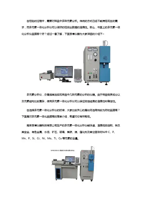
南京思博仪器科技有限公司生产的多元素一体化分析仪能快速、准确地测定钢、铁及其合金、有色金属、水泥、矿石、玻璃、焦碳、煤、催化剂及其它固体材料中C、P、Mn、P、Si、Cr、Ni、Mo、Ti、Cu等元素的含量。
南京思博仪器科技有限公司生产的SHW2000-D 高频红外多元素分析仪。
是集光、机、电、计算机、分析技术等于一体的高新技术产品,具有测量范围宽、分析结果准确可靠等特点。
采用仪器的智能化、屏幕显示的图、文及数据的采集、处理等,是诸多行业测定微量元素理想的分析设备。
以上是对多元素一体化分析仪的文章介绍,如有这方面的需求,可咨询专业的生产厂家:南京思博仪器科技有限公司或者登录官网:进行了解。
南京思博仪器科技有限公司,致力于材料检测的发展和应用。
是拥有自主知识产权以高速分析仪器研制、开发、制造、市场营销为一体的现代化高科技公司。
公司专业制造系列直读光谱仪、红外碳硫分析仪、炉前铁水质量管理仪和金属材料分析仪等产品。
可分析碳、硫、硅、锰、磷、镍、铬、铜、钼、铁、钛、稀土、镁等多种元素。
产品广泛应用于钢铁、冶金、铸造、机械、建筑、大专院校、石油化工、技术监督等部门及进出口商检等领域。
产品获国家多项专利证书,可检测钢、铁及铁合金、铝合金、铜合金、锌合金、锡、铅合金、预处理溶液、镀液、钢铁氧化液及磷化液等多种材料中各种化学成份的含量。