西门子TD编程手册
- 格式:pdf
- 大小:6.17 MB
- 文档页数:195

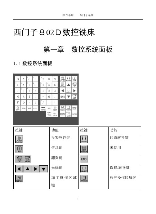
西门子802D数控铣床第一章数控系统面板1.1数控系统面板按键功能按键功能报警应答键通道转换键信息键未使用翻页键光标键选择/转换键程序操作区域键加工操作区域键参数操作区域键程序管理操作区域键报警/系统操作区域键字母键上档键转换对应字符数字键上档键转换对应字符上档建控制键替换键空格键退格删除键删除键插入键制表键回车/输入键1.2机床控制面板按键功能按键功能增量选择键点动参考点自动方式单段手动数据输入主轴正转主轴翻转主轴停Z轴点动X轴点动Y轴点动快进键复位键数控停止数控启动急停键主轴速度修调进给速度修调1.3屏幕显示区显示屏右侧和下方的灰色方块为菜单软键,按下软键,可以进入软键左侧或上方对应的菜单。
有些菜单下有多级子菜单,当进入子菜单后,可以通过点击“返回”软键,返回上一级菜单。
第二章手动操作2.1返回参考点1.进入系统后,显示屏上方显示文字:0030:急停。
点击急停键,使急停键抬起。
这时该行文字消失;2.按下机床控制面板上的点动键,再按下参考点键,这时显示屏上X、Y、Z坐标轴后出现空心圆(如下图);3.分别按下、、键,机床上的坐标轴移动回参考点,同时显示屏上坐标轴后的空心圆变为实心圆,参考点的坐标值变为0。
2.2 JOG运行方式2.2.1JOG运行1.按下机床控制面板上的点动键;2.选择进给速度;3.按下坐标轴方向键,机床在相应的轴上发生运动。
只要按住坐标轴键不放,机床就会以设定的速度连续移动。
2.2.2JOG进给速度选择使用机床控制面板上的进给速度修调旋钮选择进给速度:右键点击该旋钮,修调倍率递增;左键点击该旋钮,修调倍率递减。
用右键每点击一下,增加5%;用左键每点击一下,修调倍率递减5%。
2.2.3快速移动先按下快进按键,然后再按坐标轴按键,则该轴将产生快速运动。
2.2.4增量进给1.按下机床控制面板上的“增量选择”按键,系统处于增量进给运行方式;2.设定增量倍率;3.按一下“+X”或“-X”按键,X轴将向正向或负向移动一个增量值;4.依同样方法,按下“+Y”、“-Y”、“+Z”、“-Z”按键,使Y、Z轴向正向或负向移动一个增量值;5.再按一次点动键可以去除步进增量方式。

西门子802D系统操作编程说明书目录部分:第一篇编程说明第一章编程基础1.1西门子802D系统简介1.2编程基础知识1.3程序的构成第二章G功能指令详解2.1概述2.1.1数控车床中轴的定义2.1.2各坐标系含义2.1.3零点偏置2.1.4绝对及增量式编程2.2G代码介绍2.2.1快速定位G002.2.2直线插补G012.2.3圆弧插补G02、G032.2.4刀尖圆弧半径补偿2.2.5暂停G042.2.6工件坐标系及零点偏置2.2.7螺纹切削G332.2.8每分钟、每转进给G94、G952.2.0恒线速切削控制G96第三章高级编程及循环功能3.1子程序功能3.2计算参数R及各计算功能3.3车削循环功能3.3.1CYCLE95毛坯切削3.3.2CYCLE97螺纹切削循环3.3.3第二篇操作说明第一章基础介绍第二章安全操作第三章手动操作3.1回零的操作3.2手动轴的操作3.2.1手动轴的移动3.2.2手轮的操作3.3主轴的操作3.3.1正、反点的操作3.3.2正、反转的操作3.3.2.1主轴换档的操作第四章编辑操作4.1程序的建立4.2程序编辑4.3程序的检查4.4程序的运行4.5自动加工功能的使用4.5.1DRY空运行4.5.2M01有条件程序停止和M00无条件程序停止4.5.3SKP跳过程序段4.5.4PRT程序测试4.5.5第五章参数设置操作5.1刀具参数5.2手动参数5.3设定参数5.4R参数5.5第六章通讯操作6.1程序的读入及读出6.2存储卡的使用6.3在线加工的使用6.4第七章第一篇编程说明第一章编程基础1.1西门子802D系统简介西门子802D系统是西门子公司在2002年针对中国大陆市场发行的一款全简体中文的数控系统,它以其友好的操作界面,强大的数控加工功能,在国内数控机床中占有了非常大的比重.西门子802D 系统是西门子840D系统的简化版,拥有大部分840D的数控功能,窗口式操作界面,极大的方便操作人员的使用,并拥有非常强大的维护、诊断功能。

固定式螺杆空气压缩机操 作 手 册PLC 控制昆泰克空气系统技术有限公司 Q-Tech Air System Technologies Co.Ltd.部分Ⅳ-操作程序 HMI 控制面板的操作启动-按下启动按钮启动压缩机。
如果此时的压力高于加载设定点,压缩机将进入一个A/D 待机模式,在压力降低之前将不会启动。
停机-按下停止按钮将压缩机停机,并且排空压缩机。
通行口令-在控制面板上改变数据时,需要一个通行口令。
这个口令一旦输入,便处于工作状态,在没有出现无操作人员输入这种状况两分钟时间之内,不需再次输入。
时间-按下时间按钮,便可显示各种过滤器的滤芯、分离器以及压缩油所剩下的时间。
SE = 分离器 AF = 空气过滤器FF = 压缩油过滤器 FL = 压缩油o当时间达到“0”时,运行的显示上出现一条信息。
按下ENTER 去清除这条信息,然后重新设定计数器,设定在PARAM 中的预设定值。
o按下上/下箭头,显示压缩机的加载以及总的运行时间。
模式-按下模式按钮,设定操作状态。
这部分有两个菜单。
自动-双重时间-这个时间压缩机将卸载运行(几分钟)直到电机停机。
这时,将是一个待机状态,当压力降到加载压力点时,它将重新启动。
自动-重新启动-在电源供电停止之后,一个选件的定时器可重新启动压缩机。
此定时器是用秒进行设定的。
A0.0设定是将其处于OFF 状态。
此定时器的的最小时间设定是60秒,最大是120秒。
按下按钮直到下一个菜单。
卸载点: 加载点:-加载点以及卸载点可在屏幕上进行调整。
加载和卸载设定点的微分必须是10 psi 或更大。
主屏幕-按下此按钮回到主屏幕,主屏幕上显示了该压缩机的所有状态。
该显示的下面部分是那些表示不具危险的运行信息,比如象“压缩机停机”、“卸载运行”、“远程停止” 以及过滤器服务时间超时等。
警报-如果发生运行中的警报,压缩机将停机。
按下ALARM ,进入停机状态菜单,按下ENTER 键则是清除警报。

SIMATICS7/HMISIMATIC Automation Tool SDK V3.1 SP2 Product informationProduct InformationSiemens AG Division Digital Factory A5E45252984-AAⓅ 10/2018 Subject to changeCopyright © Siemens AG 2018.All rights reservedLegal informationWarning notice systemThis manual contains notices you have to observe in order to ensure your personal safety, as well as to preventdamage to property. The notices referring to your personal safety are highlighted in the manual by a safety alertsymbol, notices referring only to property damage have no safety alert symbol. These notices shown below aregraded according to the degree of danger.indicates that death or severe personal injury will result if proper precautions are not taken.WARNINGindicates that death or severe personal injury may result if proper precautions are not taken.CAUTIONindicates that minor personal injury can result if proper precautions are not taken.NOTICEindicates that property damage can result if proper precautions are not taken.If more than one degree of danger is present, the warning notice representing the highest degree of danger willbe used. A notice warning of injury to persons with a safety alert symbol may also include a warning relating toproperty damage.Qualified PersonnelThe product/system described in this documentation may be operated only by personnel qualified for the specifictask in accordance with the relevant documentation, in particular its warning notices and safety instructions.Qualified personnel are those who, based on their training and experience, are capable of identifying risks andavoiding potential hazards when working with these products/systems.Proper use of Siemens productsNote the following:WARNINGSiemens products may only be used for the applications described in the catalog and in the relevant technicaldocumentation. If products and components from other manufacturers are used, these must be recommendedor approved by Siemens. Proper transport, storage, installation, assembly, commissioning, operation andmaintenance are required to ensure that the products operate safely and without any problems. The permissibleambient conditions must be complied with. The information in the relevant documentation must be observed. TrademarksAll names identified by ® are registered trademarks of Siemens AG. The remaining trademarks in this publicationmay be trademarks whose use by third parties for their own purposes could violate the rights of the owner. Disclaimer of LiabilityWe have reviewed the contents of this publication to ensure consistency with the hardware and softwaredescribed. Since variance cannot be precluded entirely, we cannot guarantee full consistency. However, theinformation in this publication is reviewed regularly and any necessary corrections are included in subsequenteditions.Table of contents1 Components of the SIMATIC Automation Tool SDK (4)Components of the SIMATIC Automation Tool SDK 1 The SIMATIC Automation Tool Software Development Kit (SDK) consists of the followingcomponents:●Setup application for installing the SDK●SIMATIC Automation Tool Application Programming Interface (API): a set of .NETinterfaces, classes, and methods to perform network and device operations● A Windows installer package to use in creating a setup for your users. Your users caninstall your custom application from the setup you create. The installer provides for asilent installation of the API and S7 communication components with no licenserequirement.●Product Information●Installation Notes●User Guide●Totally Integrated Automation UPDATER (TIA Software Updater) for performing futureupdates to the SDK。


西门子TD400 显示屏操作说明本说明书适用于目前采用西门子S7-200 PLC的螺杆压缩机按键功能TD400显示屏上共有ESC、ENTER、▲、▼、◥、◣、F1~8、SHIFT等,共15个按键。
ESC键:退出当前页面或菜单ENTER键:确认键▲键:往上翻页或数字增加▼键:往下翻页或数字减少◥、◣键:移位1、TD400C的设定:在TD400C第一次上电时,需要对TD400C进行设定,主要是参数块地址,请在光标处闪动输入2103,其他为默认值在当前页面上按ESC键,退到以下设定页面。
然后按ENTER键,进行参数设定,2、压缩机参数设定和修改在当前页面上按一次ESC键,退出到主菜单页面,选择相应的选项,进行设定。
不需要输入密码的参数修改用▲▼键找到“参数设定2”项目,按ENTER键,进入参数设定具体页面,根据页面提示,输入具体数值。
数值的增减可通过▲▼键完成,参数设定完毕,按ENTER确认键,设定完毕。
需要输入密码的参数修改用▲▼键找到“参数设定1”项目,按ENTER键,进入密码输入页面,然后进入参数设定具体页面,根据页面提示,输入具体数值。
数值的增减可通过▲▼键完成,参数设定完毕,按ENTER确认键,设定完毕。
机旁控制和远程控制设定默认为机旁控制,如果不进行设定,压缩机被设定为机旁控制状态。
如输入2222,压缩机被设定为远程控制状态。
压力高延时停机功能开通和关闭设定压力高延时停机功能开通时,当压缩机的排气压力达到上限后,如果在设定的时间内,压缩机的排气压力还没有降低于压力下限时,压缩机自动停机;当压缩机的排气压力降低与压力下限时,压缩机自动起动。
默认为压力高延时停机功能关闭。
如输入2222,则压力高延时停机功能开通。
参数星三角时间:15S压力上下限:根据机型温度上下限:110~0排污开: 4秒排污关; 4分电机间隔起动时间: 120S最短停机时间:120S压高延时停机时间: 10分延时停机时间 : 15S3、报警查看当显示屏出现感叹号时,说明有报警或停机故障出现,这时可进入报警页面,查看报警内容。

TDC操作⼿册TDC Ethernet communicationSIEMEMS A&D CSCatalog :1 TDC IE communication introduction 3steps 4 2 TDCconfigurationsteps 14 3 S7-400configurationconnection 25 4 Physicalform 26 5 Feedback1. TDC IE communication introductionTDC system is the newest digital control system of SIMADYN D family and it has the highest quality in the SIMATIC control system family .As one part of TIA family it has powerful communication function . The system provides the MPI communication protocol , Profibus communication protocol , Ethernet communication protocol . It is easy to communicate with other simatic product , for example S7-300 , S7-400 , HMI and drives product .For Ethernet communication , the hardware platform is CP5100 which supply a standard RJ45 Ethernet interface , other interface will be available in future .For communication task , system can exchange process data with other TDC system or PLC S7 system through CP5100 module .For communication protocol , TDC system supplies TCP/IP protocol and /or UDP protocol .For transfer modes , refresh mode , handshake mode , multiple mode and select mode are available for selection .For net speed it can work with 10Mbit and 100Mbit network , the module can automatically sense the net speed .2. TDC configuration steps2.1 Hardware configuration in Simatic manager1. create a new S7 project2. insert a TDC station3. select hardware configuration in Simatic manager , double click to open it4. insert the subrack , CPU , communication board CP5100 and other module from the hardware catalogkeep the same type with which is used in the sub rack .5. define the CPU module and communication module properties .For CP5100 , we need to define the module name firstlyFor Ethernet property we need to define the IP address and subnet mask .6. save and compiled the hardware configuration .2.2 CFC programming1. Insert a CFC program in Simaticmanager ,double click it to open it .2. insert the TCPIP communication block intothe chart , define the connection addresswhich is set in the hardware configurationand select the proper cycle time .3. insert the send function block CTV_P ,define the connection :CTS CP5100 hardware address which isset in hardware configuration AT channel name . protocol type –CP5100 port number . partner IPaddress – partner port numberexample : 'TRAN.T-02004.140080000003- 02002' mod normally we select handshake mode EN set to 1 to enable the FB NBY define the telegram length in bytes4. insert the DWR_D block to write thecommunication content to thecommunication buffer .Here we can define the offset in thecommunication buffer by set connector1/2 . The final result is the sum of offset1 and offset2 .For connector SWP we set it to 1 .The data we try to send is set in connector X ,here is 44 as a example .For receive part , we can do it in the same way .For connector AR of CRV_P , we do not needto define the partner IP address – partner port Number .5. compiled the program and download it to thememory card and restart the system .3.S7-400 configuration steps3.1 S7 hardware configurationFirst insert the S7-400 station , then open thehardware configuration to insert the modulewhich are available on the sub rack .For CP443-1 module we need to define the MACaddress , IP address and subnet mask .The IP address will be used in the CFC program .3.2 network configuration in the Netprosoftwareopen Netpro under hardware configurationmenuselect the CPU in the Simatic station and insert the new connection , select unspecified station andTCP connection ,select apply button .select the ID number ,record the address .Both of them will be used in the S7 program .Under address menu we need to setthe local port number ,partner address andport number ,select OK button to confirm the setting .For other connection you need , you can do it in the same way . Then we need to save and compile the configuration .。


s功能块SIMATIC TDC手册 12/2004版本手册包含应该遵守的注意事项,以确保人身安全,保护产品和连接的设备。
这些注意事项在本手册中都以警告三角符号高亮显示,并根据危险级别做如下标记:!危险表示存在非常危险的情况,如果不避免,将造成死亡或严重的人身伤害。
!警告 表示存在潜在的危险情况,如果不避免,可能造成死亡或严重的人身伤害。
!注意 如果与安全警示符号一同使用,表示存在潜在的危险情况,如果不避免,可能会造成轻度或中度的人身伤害。
注意如果不与安全警示符号一同使用,表示存在潜在的危险情况,如果不避免,可能造成财产损失。
注意如果不与安全警示符号一同使用,表示存在潜在的情况,如果不避免,则可能导致意想不到的结果或状态。
注意以下内容:本设备及其组件只能用于目录或技术说明中描述的应用,并且只能与西门子认可或建 议的其它制造商生产的设备或组件相连接。
SIMATIC ® 和 SIMADYN D ® 是 Siemens AG 注册商标。
第三方出于个人目的而使用本文档中与商标相关的任何其它名称都将可能侵犯商标所有者的权利。
安全指南正确使用商标版权所有 © SIEMENS AG 2004 保留所有权利 免责说明未经明确地书面授权,不得复制、转让或使用本文档或其内容。
否则,违者将对造成的损害负责。
保留所有权利,包括专利许 可、实用模型或设计的注册所拥有的权利。
Siemens AG A&DFrauenauracher Strasse 80 91056 Erlangen我们已证实本手册中的内容与所述硬件和软件相符。
但是,由于错误在所难免,因此无法保证完全一致。
然而,本手册中的数据将进行定期检查,并在后续版本中做出必要的更正。
欢迎提出改进建议。
© Siemens AG 2004保留对技术数据进行更改的权利。
版本SIMATIC TDC 手册 功能块 12/2004版注意请注意,本文档的当前版本中所包含的各个章节,其版本是不同的。


2.4.7Tapping with compensating chuck - CYCLE840ProgrammingCYCLE840 (RTP, RFP, SDIS, DP, DPR, DTB, SDR, SDAC, ENC, MPIT, PIT, AXN) ParametersParameter Data type DescriptionRTP REAL Retraction plane (absolute)RFP REAL Reference plane (absolute)SDIS REAL Safety clearance (enter without sign)DP REAL Final drilling depth (absolute)DPR REAL Final drilling depth relative to the reference plane (enter withoutsign)DTB REAL Dwell time at thread depth (chip breakage)SDR INT Direction of rotation for retractionValues: 0 (automatic direction reversal), 3 or 4 (for M3 or M4) SDAC INT Direction of rotation after end of cycleValues: 3, 4 or 5 (for M3, M4 or M5)ENC INT Tapping with/without encoderValues: 0 = with encoder, 1 = without encoderMPIT REAL Thread lead as a thread size (signed):Range of values 3 (for M3) to 48 (for M48)PST REAL Thread lead as a value (signed)Range of values: 0.001 ... 2000.000 mmTool axisAXN INTValues1):1: 1st axis of the current plane2: 2nd axis of the current plane3: 3rd axis of the current plane1)The definition of the 1st, 2nd, and 3rd axes depends upon the current plane selected. FunctionThe tool drills at the programmed spindle speed and feedrate to the entered final threaddepth.This cycle is used to program tapping with the compensating chuck:●Without encoder●With encoder.SequenceTapping with compensating chuck without encoderPosition reached prior to cycle start:The drilling position is the position in the two axes of the selected plane.The cycle creates the following sequence of motions:●Approach of the reference plane brought forward by the safety clearance by using G0●Tapping to the final drilling depth●Dwell time at tapping depth (parameter DTB)●Retraction to the reference plane brought forward by the safety clearance●Retraction to the retraction plane with G0Sequence of operationsTapping with compensating chuck with encoderPosition reached prior to cycle start:The drilling position is the position in the two axes of the selected plane.The cycle creates the following sequence of motions:●Approach of the reference plane brought forward by the safety clearance by using G0●Tapping to the final drilling depth●Dwell time at thread depth (parameter DTB)●Retraction to the reference plane brought forward by the safety clearance●Retraction to the retraction plane with G0Explanation of the parametersFor the parameters RTP, RFP, SDIS, DP, DPR, refer to Section "Drilling, centering -CYCLE81 (Page 122)".DTB (dwell time)The dwell time must be programmed in seconds.SDR (direction of rotation for retraction)SDR=0 must be set if the spindle direction is to reverse automatically.If the machine data is defined such that no encoder is set (in this case, machine dataMD30200 $MA_NUM_ENCS is 0), the parameter must be assigned the value 3 or 4 for thedirection of rotation; otherwise, alarm 61202 "No spindle direction programmed" is outputand the cycle is aborted.SDAC (direction of rotation)Because the cycle can also be called modally (see Section "Graphical cycle support in theprogram editor (Page 118)"), it requires a direction of rotation for tapping further threadedholes. This is programmed in parameter SDAC and corresponds to the direction of rotationprogrammed before the first call in the higher-level program. If SDR=0, the value assigned toSDAC has no meaning in the cycle and can be omitted in the parameterization.ENC (tapping)If tapping is to be performed without encoder although an encoder exists, parameter ENCmust be assigned value 1.If, however, no encoder is installed and the parameter is assigned the value 0, it is ignored inthe cycle.MPIT and PIT (thread lead as a thread size and as a value)The parameter for the lead is only relevant if tapping is performed with encoder. The cycle calculates the feedrate from the spindle speed and the lead.The value for the thread lead can be defined either as the thread size (for metric threads between M3 and M48 only) or as a value (distance from one thread turn to the next as a numerical value). Any parameters not required are omitted in the call or assigned the value zero.If the two lead parameters have conflicting values, alarm 61001 "Thread lead wrong" is generated by the cycle and cycle execution is aborted.NoteDepending on the settings in machine data MD30200 $MA_NUM_ENCS, the cycle selects whether tapping is to be performed with or without encoder.The direction of rotation for the spindle must be programmed with M3 or M4.In thread blocks with G63, the values of the feedrate override switch and spindle speed override switch are frozen to 100%.A longer compensating chuck is usually required for tapping without encoder.AXN (tool axis)The following figure presents the options for the drilling axes to be selected.With G17:●AXN=1; Corresponds to X●AXN=2; Corresponds to Y●AXN=3; Corresponds to ZUsing AXN (number of the drilling axis) to program the drilling axis enables the drilling axis tobe directly programmed.AXN=1 1st axis of the current planeAXN=2 2nd axis of the current planeAXN=3 3rd axis of the current planeFor example, to machine a hole in the G17 plane with Z axis, you program:G17AXN=3Programming example: Tapping without encoderIn this program, a thread is tapped without encoder at position X35 Y35 in the XY plane; thetapping axis is the Z axis. The parameters SDR and SDAC for the direction of rotation mustbe assigned; parameter ENC is assigned the value 1, the value for the depth is the absolutevalue. Lead parameter PIT can be omitted. A compensating chuck is used in machining.N10 G90 G0 T11 D1 S500 M3 ; Specification of technologyvaluesN20 G17 X35 Y35 Z60 ; Approach drilling positionN30 G1 F200 ; Setting the path feedrateN40 CYCLE840(20,0,3,-15,,1,3,4,1,6,,3) Cycle call, dwell time 1 s,direction of rotation forretraction M4, direction ofrotation after cycle M3, nosafety clearance, parameters MPITand PIT have been omittedN50 M02 ; End of programProgramming example: Tapping with encoderIn this program, a thread is tapped with encoder at position X35 Y35 in the XY plane. Thedrilling axis is the Z axis. The lead parameter must be defined, automatic reversal of thedirection of rotation is programmed. A compensating chuck is used in machining.N10 G90 G0 T11 D1 S500 M4 ; Specification of technologyvaluesN20 G17 X35 Y35 Z60 ; Approach drilling positionN30 CYCLE840(20,0,3,-15,,1,3,4,1,6,,3) ; Cycle call, without safetyclearance, with absolute depthspecificationN40 M02 ; End of program。

Step 30. Select the Deadband Value Submenu Press d . The display will show 020.0, otherwisepress b or c.Press d to store and advance to next menu item.Step 31. Enter the Alarm 2 MenuThe display will show ALR2the top menu for Alarm 2.Repeat steps from 29 and 30 to set for Alarm 2 the same conditions as for Alarm 1.Step 32. Configuration of Display Color Selection Press a until the COLR Display Color Selection Menu appears on the Display. Configure COLR as N.CLR /GRN (green), 1.CLR / RED (red), 2.CLR /AMBR (amber). Please refer to the operator’s manual if needed.For color change on Setpoints refer to Owners Manual Section 2.Step 33. Run a TestPress a until reset the controller and return to RUN Mode to display 075.0(Ambient Temperature). Now you are ready to observe temperature as it rises 10°F higher thandisplayed. Touch the tip of the Thermocouple to raise the temperature above the Alarm 2 High value 082.0, and AL2will turn on, and Display Color will change from Green to Amber. Continue touching the tip to raise the temperature above the Alarm 1 High value 087.0and Display Color will change from Amber to Red. Annunciator “1” is turning on and off displaying output 1.Step 11. Enter to the Thermocouple Type Input Submenu Press d to display flashing, previously selected Thermocouple type.Step 12. Scroll through available selection of TC types Press b to sequence thru flashing Thermocouple types,(select k -for type "K" CHROMEGA ®/ALOMEGA ®)J K T E N DIN J R S B C - TC types J k t E N dN J R S b C - DisplayStep 13. Store TC typeAfter you have selected the Thermocouple type press d to store your selection, the instrument automatically advances to the next menu item.Step 14. Enter to Reading Configuration MenuThe display shows RDG Reading Configuration, which is the top menu for 4 submenus: Decimal Point, Degree Units,Filter Constant and Input/Reading Submenus.Step 15. Enter to Decimal Point Submenu Press d to show DEC Decimal Point.Step 16. Display the Decimal Point positionPress d again to display the flashing Decimal Point position.Step 17. Select the Decimal Point position Press b to select FFF.F Decimal Point position.Step 18. Store selected Decimal Point positionBy pressing d momentarily the Decimal Point position will be stored and the instrument will go to the next menu item.Step 19. Enter to Temperature Unit Submenu Display shows TEMP Temperature Unit.Step 20. Display available Temperature Units Press d to display the flashing Degree °F or °C .Step 21. Scroll through Temperature Units selection Press b to select °F Degree.Step 22. Store the Temperature UnitPress d to display momentarily that the Degree Unit has been stored and the instrument will go automatically to the next menu item.Step 23. Enter the Filter Constant Submenu Display shows FLTR Filter Constant Submenu.Step 24. Display the Filter Constant Value Submenu Press d to display the flashing, previously selected Filter Constant.Step 25. Scroll through available Filter Constants Press b to sequence thru Filter Constants 0001, 0002,0004, 0008, 0016, 0032, 0064and 0128.Step 26. Store the Filter ConstantPress d momentarily to store 0004Filter Constant and the instrument will automatically go to the next menu item.Step 27. Enter Alarm 1 MenuPress a until the ALR1Alarm 1 Menu appears on the Display. In the following steps we are going to DisableLatch, Active Above, Deadband 020.0, and above Setpoint 1Value will activate Alarm 1.Step 28. Select Latch Type SubmenuPress d to display flashing DSBL / ENBL .If flashing DSBL is displayed, press a , if ENBL is displayed, press b until DSBL is displayed, then press d to store and go to the next menu item.Step 29. Select the Above Type of Active Submenu Press d . If flashing ABoV Above is displayed, press a ,otherwise press b until ABoV is displayed. Press d to store and advance to next menu item.MQS3720-SM/0305WARNING:These products are not designed for use in, and should not be used for, patient-connected applications.It is the policy of OMEGA to comply with all worldwide safety and EMC/EMI regulations that apply.OMEGA is constantly pursuing certification of its products to the European New Approach Directives.OMEGA will add the CE mark to every appropriate device upon certification.The information contained in this document is believed to be correct, but OMEGA Engineering,Inc.accepts no liability for any errors it contains, and reserves the right to alter specifications without notice.TRADEMARK NOTICE:®,®,, andare Trademarks ofOMEGA ENGINEERING, INC.®SPECIFICATIONAccuracy:+0.5°C temp;0.03% rdg. process typical Resolution:1°/0.1°; 10 µV process Temperature Stability:0.04°C/°C RTD;0.05°C/°C TC @ 25°C (77°F); 50 ppm/°C process Display:4-digit, 7-segment LED, 101.6mm (4.00”)with red, green, and amber programmable colors for process variable, set point and temperature units.Input Types:Thermocouple, RTD, Analog Voltage and Current TC: (ITS 90)J, K, T, E, R, S, B, C, N, L RTD: (ITS 68)100/500/1000 ohm Pt sensor2-, 3-, or 4-wire; 0.00385 or 0.00392 curve Voltage:0 to 100 mV, 0 to 1 V, 0 to 10 Vdc Current:0 to 20 mA (4 to 20 mA)Output 1†:Relay 250 Vac @ 3 A Resistive Load,SSR, Pulse, Analog Voltage and Current Output 2†:Relay 250 Vac @ 3 A Resistive Load,SSR, Pulse†Only for AlarmsOptions:Communication RS-232 / RS-485 or Excitation:24 VdcPower:100-240 Vac ±10%,50-60 Hz, 22.5 W Dimensions:480.0L x 210.8W x 95.4D mm (18.11" x 8.31" x 3.76")Panel Cutout:414.3 L x 179.4 W mm (16.31” L x 7.06” W)Weight:2,495 g (5.5 lbs)Approvals:CE per EN61010-1:2001This Quick Start Reference provides information onsetting up your instrument for basic operation. Thelatest complete Communication and OperationalManual as well as free Software and ActiveXControls are available at or onthe CD-ROM enclosed with your shipment.The instrument is a panel mount device protected in accordance with EN 61010-1:2001, electrical safety requirements for electrical equipment for measurement, control and laboratory.Remember that the unit has no power-on switch. Building installation should include a switch or circuit-breaker that must be compliant to IEC 947-1 and 947-3. SAFETY:•Do not exceed voltage rating on the label located onthe back of the instrument housing.•Always disconnect power before changing signal andpower connections.•Do not use this instrument on a work bench withoutits case for safety reasons.•Do not operate this instrument in flammable orexplosive atmospheres.EMC:•Whenever EMC is an issue, always use shielded cables.•Never run signal and power wires in the same conduit.•Use signal wire connections with twisted-pair cables.•Install Ferrite Bead(s) on signal wire close to theinstrument if EMC problems persist.。

12中文 TD 200 使用说明概述TD 200文本显示器是所有SIMATIC S7-200系列操作员界面问题的最佳解决方法只需用它提供的连接电缆接到S7-200系列PPI接口上即可TD200具有下列用途在控制系统中起设定和修正参数的作用改变动作设定实l时时钟的时间等提供密码保护功能l牢固的塑料壳l27mm的安装深度或用作手持设备l即使在逆光情况下也易看清TD 200中文版内置国标汉字库l内置连接电缆的接口l需接额外电源功能TD200具有下列功能用选择项确认方法可显示最多80条信息五种系统语言l可设定实时时钟l提供强制I/O点诊断功能l提供密码保护功能l过程参数的显示和修改例如l可编程的8个功能键可以替代普通的控制按钮这样还可以节省8个输入l点输入和输出的设定l例如测试时进行设置和诊断可以不用其它的操作设备即可实现对电动机的控制编程TD200用STEP 7-Micro/WIN软件进行编程在S7-200系列的CPU中保留了一个专用区域用于与TD200交换数据中文TD 200使用说明支持多种亚洲文字的TD200目前已在国内广泛使用为使广大用户更加容易地使用TD200步骤一点击Next键步骤三选择Simplified Chinese项步骤五然后点击Next 键步骤六然后点击Next 键F1-F8Ëù¶步骤7È»ºóµã»÷Next 键步骤8È»ºóµã»÷Next 键步骤九然后点击Finish 键步骤十VB0 'TD' //TD200数据块的标志VB2 16#60 //设置为中文, 更新速率尽可能快VB3 16#B0//设置20个字符模式;上箭头对应的位是V3.2F1~SHIFT+F4VW6 34 //设置信息起始地址为 VW34 VW8 14 //设置信息使能位的地址为VW14 VW10 0 //用于设置全局密码保护VW12256//设置字符集为简体中文。
