El-Yamine KETTAL
- 格式:pdf
- 大小:124.55 KB
- 文档页数:15


专利名称:Guiding catheter发明人:Koyama, Yutaka,Tanikawa, Masahiro c/oNipro Corporation申请号:EP08012493.6申请日:20080710公开号:EP2016969A1公开日:20090121专利内容由知识产权出版社提供专利附图:摘要:A guiding catheter (1) for a coronary artery is easily inserted into the coronary artery even via a trans-radial coronary intervention using a small-diameter guidingcatheter and hardly comes off from the coronary artery thanks to a strong pushing force.The guiding catheter (1) includes a distal end portion (11); a main body (10); and a curved portion which is provided between the distal end portion (11) and the main body (10), wherein the curved portion includes a first curved portion (12) on a distal end portion side and a second curved portion (14) on a proximal end portion side, and the first curved portion (12) having a small curvature radius and the second curved portion (14) having a large curvature radius are continuously curved in the same direction.申请人:Nipro Corporation地址:9-3, Honjo-nishi 3-chome Kita-ku, Osaka-shi, Osaka-fu, 531-8510 JP国籍:JP代理机构:Sticht, Andreas更多信息请下载全文后查看。

O-kroužky průvodce materiályInovace v konstrukci,materiálech a v aplikaci těsněníVlastní vývoj materiálůDisponujeme jedinečnou databází více než 2000 materiálových receptur založených na elastomerech, PTFE a termoplastických technologiích. Sem patří i nejodolnější polymery určené pro vy-soké zatížení v prostředí s teplotami od –254°C do +325°C. Pokračující výzkum nám zajišťuje přední místo ve vývoji nových materiálů, které by odpovídaly vysokým požadavkům na funkci i nejpřísnějším nárokům na bezpečnost a ekologii. K námi vy-vinutým materiálům patří Isolast®, Turcon®, Turcite®, Zurcon®, Orkot®, Luytex® a HiMod®.Vlastní testovací zařízeníNejmodernější zkušební laboratoře nám umožňují rozsáhlé testy materiálů i hotových výrobků s cílem vyhovět rostoucím poža-davkům na tlak a teplotu, poskytovat špičkový výkon a minima-lizovat riziko závad. To rovněž zahrnuje hodnocení pracovních kapalin. Naše vývojová a testovací zařízení vyhovují ekologic-kým předpisům EC a EPA.Efektivní výrobaDíky strategickému rozmístění výrobních závodů a špičkovým technologiím jsme schopni zajistit moderní a efektivní výrobu ve všech oblastech po celém světě. Jednotně organizované výrob-ní jednotky jsou zárukou té nejlepší kvality v procesu od návrhu výrobku a materiálu až po výrobu, finální montáž a dopravu.Záruka kvalityZárukou kvality našich výrobků je stálá inovace výrobních pro-středků a postupů a oddanost zásadě bezchybné produkce. Všechny naše závody splňují požadavky norem ISO 9000, QS 9000, AS 9000 nebo Ford Q1.Údaje v katalogu vycházejí ze zkušeností mnoha desítek let vý-roby a používání těsnicích prvků a plastických hmot. Přesto všakmohou některé neznámé parametry a podmínky ovlivnit všeobec-ně platná pravidla takovým způsobem, že je nutné, aby uživatelsám prováděl potřebné zkoušky. Z tohoto důvodu, a také proto,že oblast aplikací našich výrobků je velice rozsáhlá, Busak+Sham-ban nemůže převzít záruky za správný výběr údajů a doporučeníkatalogu v těchto jednotlivých případech použití.Mezní hodnoty tlaku, teploty a rychlosti uvedené v katalogu jsoumaximální hodnoty naměřené v laboratoři. Při použití musí být pa-matováno na to, že vlivem střídavých změn provozních podmínekse tyto hodnoty odpovídajícím způsobem snižují. Při mimořádnýchprovozních podmínkách se obraťte na naše odborníky.Toto vydání nahrazuje všechna předchozí. Tento katalog nebojakákoliv jeho část nesmí být dále rozmnožován bez našehosvolení.® Všechny ochranné známky jsou majetkem Busak+Shamban,Dowty Engineered Seals, Forsheda. QUAD-RING® je ochrannáznámka Quadion Corporation.© Busak+Shamban 2004. Všechna práva vyhrazena.Tyrkysová barva je ochrannou známkou Busak+Shamban.Průvodce materiály■ ObsahÚvod. . . . . . . . . . . . . . . . . . . . . . . . . . . . . . . . . . . . . . . . . . . . . . . . . . . . . . . . . . . . . . . . . . . . . . . . . . . . . . . . . . . . . . . . . . . 3 Elastomery. . . . . . . . . . . . . . . . . . . . . . . . . . . . . . . . . . . . . . . . . . . . . . . . . . . . . . . . . . . . . . . . . . . . . . . . . . . . . . . . . . . . . . 3 Parametry použití elastomerů. . . . . . . . . . . . . . . . . . . . . . . . . . . . . . . . . . . . . . . . . . . . . . . . . . . . . . . . . . . . . . . . . . . . . . . . 5 Chemická kompatibilita. . . . . . . . . . . . . . . . . . . . . . . . . . . . . . . . . . . . . . . . . . . . . . . . . . . . . . . . . . . . . . . . . . . . . . . . . . . . 7 Materiály. . . . . . . . . . . . . . . . . . . . . . . . . . . . . . . . . . . . . . . . . . . . . . . . . . . . . . . . . . . . . . . . . . . . . . . . . . . . . . . . . . . . . . 24 Standardní materiály. . . . . . . . . . . . . . . . . . . . . . . . . . . . . . . . . . . . . . . . . . . . . . . . . . . . . . . . . . . . . . . . . . . . . . . . . . . . . 24 Materiály pro všeobecné použití. . . . . . . . . . . . . . . . . . . . . . . . . . . . . . . . . . . . . . . . . . . . . . . . . . . . . . . . . . . . . . . . . . . . 28 Materiály pro speciální použití. . . . . . . . . . . . . . . . . . . . . . . . . . . . . . . . . . . . . . . . . . . . . . . . . . . . . . . . . . . . . . . . . . . . . 30 Speciální požadavky – certifikace. . . . . . . . . . . . . . . . . . . . . . . . . . . . . . . . . . . . . . . . . . . . . . . . . . . . . . . . . . . . . . . . . . 34 Certifikované materiály. . . . . . . . . . . . . . . . . . . . . . . . . . . . . . . . . . . . . . . . . . . . . . . . . . . . . . . . . . . . . . . . . . . . . . . . . . . 36 Kritéria kvality. . . . . . . . . . . . . . . . . . . . . . . . . . . . . . . . . . . . . . . . . . . . . . . . . . . . . . . . . . . . . . . . . . . . . . . . . . . . . . . . . . . 37 Pokyny pro skladování. . . . . . . . . . . . . . . . . . . . . . . . . . . . . . . . . . . . . . . . . . . . . . . . . . . . . . . . . . . . . . . . . . . . . . . . . . . . 37Průvodce materiályPrůvodce materiály ! ÚvodVýrobci příslušenství a cíloví uživatelé očekávají těsnicí systé-my pracující po dlouhou dobu bez prosaků a bez údržby. Roz-hodující je spolehlivost vedoucí ke snížení nákladů na údržbu. Pro každou individuální aplikaci je velmi důležité najít dokonalé řešení těsnicího systému. To znamená zvolit vhodné materiály a ideální sestavu těsnicích, vodicích a stíracích prvků. Jedním ze základních a nejčastěji používaných těsnicích prvků je O-krou-žek. Při jeho použití je velmi důležitý návrh vhodného materiá-lu pro danou aplikaci.Na základě mnohaletých zkušeností s výrobou, vývojem a na-vrhováním těsnicích systémů může naše firma nabídnout širokou paletu vysoce výkonných materiálů.Nezbytnou podporu pro správný výběr materiálu O-kroužku poskytuje tento katalog.! ElastomeryJedna z hlavních materiálových skupin využívaných pro výro-bu těsnění jsou elastomery. Vykazují dobré vlastnosti jako jsou pružnost nebo dobrá chemická odolnost.Následující tabulka poskytuje přehled nejběžněji používaných elastomerových skupin. Naše firma může nabídnout velké množ-ství materiálů v každé skupině.Tabulka I Přehled elastomerůOznačeníObchodní název*Zkratka podleISO 1629ASTM 1418B+S Polyakrylátový elastomer Noxtite®Hytemp®Nipol AR®ACM ACM APolyesterový uretan Polyeterový uretanAdiprene®Pellethan®Vulcollan®Desmopan®AUEUAUEUWUWUEpichlorhydrinový elastomer Hydrin®CO CO WO Chloroprenový elastomer Baypren®Neoprene®CR CR WC Chlorsulfonovaný polyethylenový elastomer Hypalon®CSM CSM WM Ethylen-propylen dien elastomer Dutral®Keltan®Vistalon®Buna EP®EPDM EPDM EKopolymer tetrafluoroethylen-propylenového elastomeru Aflas®FEPM TFE/P**WT Perfluorovaný elastomer Isolast®FFKM FFKM J Fluorouhlíkový elastomer Dai–El®Fluorel®Tecnoflon®Viton®FKM FKM VFluorosilikonový elastomer Silastic®FVMQ FVMQ F Hydrogenovaný akrylonitril-butadienový elastomer Therban®Zetpol®HNBR HNBR H Butylový elastomer Esso Butyl®IIR IIR WIAkrylonitril-butadienový elastomer (Nitrilová pryž)Europrene®Krynac®Nipol N®Perbunan NT®Breon®NBR NBR NPřírodní pryžNR NR WRPrůvodce materiályOznačeníObchodní název*Zkratka podleISO 1629ASTM 1418B+S Styren-butadienový elastomer Buna S®Europrene®Polysar S®SBR SBR WBPolysulfidový elastomer Thiokol®–TWT WY Metyl-vinyl silikonový elastomer Elastoseal®Rhodorsil®Silastic®Silopren®VMQ VMQ S* Výběr registrovaných obchodních názvů** Zatím nenormalizovaná zkratkaASTM = American Society for Testing and MaterialsISO = International Organisation for StandardisationTabulka II Nejdůležitější typy syntetických kaučuků, jejich skupiny a označeníChemický název Zkratka podleISO 1629 (ČSN 62 0004)ASTM 1418 Skupina M(nasycený uhlíkový řetězec v hlavním makromolekulárním řetězci)– Polyakrylátový kaučuk– E thylen-akrylátový kaučuk– Chlorsulfonovaný polyethylenový kaučuk – Ethylen-propylen dien kaučuk– E thylen-propylenový kaučuk– Fluorouhlíkový kaučuk– Perfluorovaný kaučuk AC MAE MCS MEPD MEP MFK MFFK MAC MCS MEPD MEP MFK MFFK MSkupina O(molekuly kyslíku v hlavním makromolekulárním řetězci)– E pichlorhydrinový kaučuk– Kopolymer epichlorhydrinového kaučuku C OEC OC OEC OSkupina R(nenasycený uhlovodíkový řetězec v hlavním makromolekulárním řetězci)– Chloroprenový kaučuk– Butylový kaučuk– Hydrogenovaný akrylonitril-butadienový kaučuk – Akrylonitril-butadienový kaučuk– Přírodní kaučuk– Styren-butadienový kaučukC RII RHNB RNB RN RSB RC RII RHNB RNB RN RSB RSkupina Q(molekuly křemíku a kyslíku v hlavním makromolekulárním řetězci)– Fluorosilikonový kaučuk– Metyl-vinyl silikonový kaučuk FVM QVM QFVM QVM QSkupina U(molekuly uhlíku, kyslíku a dusíku v hlavním makromolekulárním řetězci)– Polyesterový uretan – Polyeterový uretan A UE UA UE UPrůvodce materiály ! Parametry použití elastomerůElastomery, jako všechny organické látky, mají omezené použití. Na vlastnosti materiálů a tedy i na jejich těsnicí schopnosti pů-sobí řada vnějších vlivů, např. různá média, kyslík, ozon a dá-le teplota a tlak. Jejich působením budou elastomery mimo jiné tvrdnout, bobtnat nebo se smršťovat, což vyvolá trhliny nebo dokonce i destrukci materiálu.Následující informace ilustrují rozdílné parametry použití jed-notlivých materiálů.Teplotní odolnost/bobtnání elastomerů v oleji Obrázek 1 Změna objemu v oleji IRM 903Průvodce materiály Rozsah teplotObrázek 2 Teplotní rozsah jednotlivých elastomerůVšeobecné oblasti použitíElastomery se používají ve velmi širokém spektru aplikací. Odol-nosti elastomerů ve speciálních médiích jsou popsány v kapitole …Chemická kompatibilita“ (str. 7–23).Jednotlivé elastomerové skupiny mohou být charakterizovány následovně:ACM (Polyakrylátový elastomer)ACM vykazuje vynikající odolnost vůči ozónu, povětrnostním vlivům a horkému vzduchu, i když má pouze průměrnou mez pevnosti, pružnost a poměrně omezené schopnosti při nízkých teplotách.Rozsah provozních teplot je od –20 °C do +150 °C (krátkodobě až do +175 °C). Speciální směsi mohou být použity až do –35 °C. Používá se především v automobilových aplikacích, které vy-žadují odolnost vůči mazivům, jejichž součástí je mnoho přísad (např. síra) a ve kterých jsou vysoké teploty. CR (Chloroprenový elastomer):CR vykazuje poměrně dobrou odolnost vůči chemikáliím, ozó-nu, povětrnostním vlivům a stárnutí. Jeho dalšími výhodami jsou dobré mechanické vlastnosti, pružnost i při nízkých teplotách a nehořlavost.Rozsah provozních teplot je od –40 °C do +100 °C (krátko-době až do +120 °C). Speciální směsi mohou být použity až do –55 °C.Používá se především v chladírenské technice, aplikacích kde je těsnění vystaveno vnějším povětrnostním vlivům a při výrobě a zpracování lepidel.EPDM (Etylen-propylen dien elastomer)EPDM vykazuje dobrou odolnost vůči vysokým teplotám, ozonu a stárnutí. Je vysoce elastický, zachovává si dobré vlastnosti i při nízkých teplotách a má dobré izolační schopnosti.Rozsah provozních teplot je od –45 °C do +150 °C (krátkodobě až do +175 °C). Typy vulkanizované sírou mají rozsah zreduko-vaný od –45 °C do +120 °C (krátkodobě až do +150 °C).Průvodce materiályPoužívá se především v aplikacích s brzdovými kapalinami (na bázi glykolu) a s horkou vodou.FFKM (Perfluorovaný elastomer)Perfluoroelastomery vykazují širokou chemickou odolnost srov-natelnou s PTFE a zároveň vynikající teplotní odolnost. Téměř ve všech médiích málo bobtnají.Rozsah provozních teplot je od –25 °C do +240 °C. Speciální směsi mohou být použity až do +325 °C.Jsou určeny pro většinu aplikací v chemickém a zpracovatel-ském průmyslu a pro aplikace s agresivním prostředím nebo vysokými teplotami.FKM (Fluorouhlíkový elastomer)FKM vykazuje, v závislosti na struktuře a obsahu fluoru v dané směsi, rozdílnou chemickou odolnost a rozdílnou pružnost při záporných teplotách. FKM je znám především pro svou nehoř-lavost, nízkou propustnost plynů, vynikající odolnost vůči ozonu, povětrnostním vlivům a stárnutí.Rozsah provozních teplot je od –20 °C do +200 °C (krátko-době až do + 230 °C). Speciální směsi FKM mohou být pou-žity až do –35 °C.Používá se především v aplikacích s médii na bázi minerálních olejů a tuků za vysokých teplot.HNBR (Hydrogenovaný akrylonitril-butadienový elastomer) HNBR se vyrábí pomocí selektivní hydrogenace butadienových skupin NBR. Vlastnosti HNBR závisí na obsahu ACN, který se pohybuje v rozmezí od 18 % do 50 %, a také na stupni nasycení dané směsi. HNBR vykazuje dobré mechanické vlastnosti. Rozsah provozních teplot je od –30 °C do +140 °C (krátko-době až do +160 °C). Speciální směsi HNBR mohou být pou-žity až do –40 °C.Používá se především v aplikacích s médii na bázi minerálních olejů a tuků.NBR (Akrylonitril-butadienový elastomer)Vlastnosti NBR závisí především na obsahu ACN (AC rylo N itril) v dané směsi. Množství ACN se pohybuje v rozmezí od 18 % do 50 %. NBR vykazuje dobré mechanické vlastnosti. Rozsah provozních teplot je od –30 °C do +100 °C (krátko-době až do +120 °C). Speciální směsi NBR mohou být použi-ty až do –60 °C.Používá se především v aplikacích s médii na bázi minerálních olejů a tuků.VMQ (Metyl-vinyl silikonový elastomer)VMQ vykazuje vynikající tepelnou odolnost, je vysoce elastický i při nízkých teplotách, má dobré dielektrické vlastnosti a mimo-řádně dobrou odolnost vůči kyslíku a ozónu.Rozsah provozních teplot je od –60 °C do +200 °C (krátkodo-bě až do +230 °C). Speciální směsi mohou být použity až do –90 °C, existují také směsi s užším teplotním rozsahem.Používá se především v lékařství a potravinářském průmyslu.! Chemická kompatibilitaPři použití tohoto průvodce je důležité mít na paměti, že uvedená hodnocení vycházejí z obecně publikovaných údajů a zkoušky ponorem. Tyto testy jsou prováděny v laboratorních podmínkách a nemusí dostatečně vyjadřovat skutečné provozní podmínky. Relativně krátké doby laboratorních zkoušek nemusí zachytit všechny vlivy, např. přísady a nečistoty, které mohou existovat v dlouhodobém provozu.Před konečným výběrem je třeba věnovat velkou pozornost všem podmínkám aplikace a je třeba důkladně zvážit jejich dopad na vybíraný materiál. Kupříkladu u některých agresiv-ních médií může jejich vyšší teplota zvýšit jejich nepříznivý do-pad na materiál.Je potřeba brát v úvahu nejen kompatibilitu materiálu s médiem, ale stejně tak jeho fyzikální vlastnosti. Trvalá deformace, tvrdost, odolnost vůči opotřebení nebo tepelná roztažnost mohou také ovlivnit použitelnost materiálu pro konkrétní aplikaci.Doporučuje se, aby uživatelé prováděli svoje vlastní zkoušky, kte-ré potvrdí vhodnost vybraného materiálu pro danou aplikaci.Pro detailnější informace o chování jednotlivých materiálů v konkrétních aplikacích kontaktujte, prosím, naše technické oddělení.Systém hodnoceníA Velmi dobrá použitelnost.Působení média nemá žádný nebo jen minimální vliv na vý-konnost a fyzikální vlastnosti elastomeru. Velmi dobrá odol-nost.B Dobrá použitelnost.Působení média má vliv na elastomer projevující se mírnou ztrátou fyzikálních vlastností. Dochází k chemickému bobt-nání.C Omezená použitelnost.Působení média má vliv na elastomer projevující se význam-nou ztrátou fyzikálních vlastností a podstatným bobtnáním.Použitelnost musí prokázat dodatečné zkoušky.U Nepoužitelný.Elastomer je nevhodný pro použití v tomto médiu.–Informace o použití v tomto médiu jsou nedostatečné.Průvodce materiályTabulka IIIChemická kompatibilitaABEFM! MateriályNásledující tabulky ukazují nejdůležitější materiály pro různé aplikace. Mimo nich máme k dispozici řadu dalších materiálů pro speciální použití. Pro další informace kontaktujte, prosím, naše technické oddělení.Uvedené materiály jsou řazeny podle elastomerových skupin, protože pro jejich mnohostranné použití je toto uspořádání nej-vhodnější. V případě speciálních průmyslových aplikací vyža-dujících certifikované materiály, jsou tyto materiály uvedeny v hlavních seznamech a navíc v samostatné přehledné tabulce certifikovaných materiálů.Vlastnosti materiálů mohou být ovlivněny nebo se mohou mě-nit, působením rozdílných podmínek v jednotlivých aplikacích, např. při použití různých médií. Proto by měly být pro každou aplikaci prováděny provozní zkoušky.! Standardní materiályNásledující tabulky uvádí fyzikální vlastnosti standardních mate-riálů naší firmy. Tabulky ukazují minimální hodnoty kterých musí standardní materiály přinejmenším dosáhnout. Mnohé z našich materiálů (i když definované jako standard) nabízejí lepší fyzi-kální vlastnosti.Jestliže ve vašich požadavcích nebudou uvedeny speciální požadavky na materiál, bude automaticky dodán, v souladu s uvedeným materiálem, jeden ze standardních materiálů (viz tabulka IX).Tabulka IVSpecifikace standardních materiálů EPDMTabulka V Specifikace standardních materiálů FKMTabulka VI Specifikace standardních materiálů HNBRTabulka VIIISpecifikace standardních silikonových materiálů VMQTabulka VIISpecifikace standardních materiálů NBRStandardní materiályTabulka IX! Materiály pro všeobecné použitíTyto materiály vyčnívají nad ostatními svým širokým spektrem použití. Mohou být použity pro standardní ale i speciální prů-myslové aplikace. O-kroužky vyrobené z těchto materiálů jsou k dispozici v různých velikostech a množstvích.Tabulka XMateriály pro všeobecné použití! Materiály pro speciální použitíTyto specializované materiály jsou určeny pro aplikace s nároč-nějšími podmínkami. V následujícím členění jsou rozděleny do dvou skupin: materiály pro zvláštní průmyslové aplikace a ma-teriály pro automobilový průmysl.Uvedené materiály jsou opět řazeny podle elastomerových sku-pin, protože pro jejich mnohostranné použití není jiné přesné uspořádání možné.Materiály pro zvláštní průmyslové aplikaceTabulka XISpeciální materiály pro průmyslové aplikaceMateriály pro O-kroužky vyráběné speciálními výrobními procesyTabulka XIIMateriály pro automobilový průmyslTyto materiály jsou převážně používány v automobilovém prů-myslu. V menších množstvích nejsou obvykle dostupné.! Speciální požadavky – certifikaceTěsnicí prvky musí často vyhovět speciálním provozním podmín-kám a těm nejtvrdším bezpečnostním požadavkům, včetně po-žadavků na ochranu životního prostředí.Rovněž schvalovací orgány a asociace působící v jednotlivých odvětvích průmyslu mají na používané materiály těsnění znač-né požadavky. To se stává často v aplikacích, kde těsnění při-chází do styku s potravinami, vodou nebo plynem. Následují-cí tabulka vyjmenovává běžné schvalovací společnosti a jejich požadavky.Tabulka XIV Certifikáty a schvalovací společnostiUvolnění/ověření/ certifikát/doporučeníAplikace Kritéria/normy Zkoušky/ověření/rozsah Instituce/společnostInstitut/laboratořACS licence Pitná voda Francouzská normaAFNOR XP P41-250,díl 1–3– analýza uvolňování …SynopticDocuments“– skladovací testy (mikrobiolo-gický rozbor)ACS(Accréditation deconformité sanitaire)Tři certifikované zkušebnílaboratoře ve Francii (Paříž,Vandoevre, Lille)BAM povoleníPlyn, kyslík– reakce na maziva– tlakové a teplotnílimity (DIN 4060)– těsnění akomponenty BAMBundesanstalt fürMaterialforschungund prüfungInstitut BAM v Německu(Berlín)BfR povolení(dřívější BgVV certifikát)Potraviny Směrnice BfR…Polymery vystavenévlivu potravin“včetněmnoha dalších norem,v závislosti naaplikaci– chemické a fyzikální zkoušky– biologické rozbory– sterilizační testy– zkoušky na ovlivnění chutiBfR(Bundesamt fürRisikobewertung)Institut BAM v Německu(Berlín)Institut hygieny a ekologiev Německu(Gelsenkirchen)DVGW povolení pro plyn Plyn, plynárenskéslužbyEN 549EN 682DVGW, Bonn(Deutscher Vereindes Gas undWasserfaches e.V.)Institut TZW v Německu(Karlsruhe)DVGW povolení pro pitnou vodu Zpracování, sklado-vání a distri b uce pit-né vodySměrnice BfR…Polymery vystavenévlivu potravin“– rozdílné zatřídění a testování,v závislosti na aplikaciDVGW, Bonn(Deutscher Vereindes Gas undWasserfaches e.V.)Institut hygieny a ekologiev Německu (Gelsenkirchen)Institut TZW v Německu(Karlsruhe)DVGW W 270 povoleníPitná voda DVGWpracovní list W 270– mikrobiologické testyzaměřené na množenímikroorganismů v materiálechDVGW, Bonn(Deutscher Vereindes Gas undWasserfaches e.V.)Institut hygieny a ekologiev Německu (Gelsenkirchen)Institut TZW v Německu(Karlsruhe)FDA doporučeníPotraviny a farmacie…White list“ rejstříkkomponentůs udělenýmpovolením podle21. CFR,díl 177.2600– zkoušky komponentů podle…White list“– rozšířené pro potravinyobsahující vodu nebo olej– vyluhovací zkoušky polárníchi nepolárních rozpouštědelFDA(Food and DrugAdministration)Vlastní nebo externízkušební laboratořeMezinárodní vojenská povoleníVojenská zařízeníMnožství vojenskýchspecifikací a standar-dů v závislosti naaplikaci– v závislosti na aplikacia předpisechRůzné zkušební laboratořeKTW certifikát Studená, tepláa horká pitná voda Směrnice BfR…Polymery vystavenévlivu potravin“ díl1.3.13– analýza uvolňování– zkoušky pachu a chuti– rejstřík uvolněných komponen-tůDVGW, Bonn(Deutscher Vereindes Gas undWasserfaches e.V.)Institut hygieny a ekologiev Německu (Gelsenkirchen)Institut TZW v Německu(Karlsruhe)Institut BAM v Německu(Berlín)。

世界十大经典鸡尾酒调制方法因为鸡尾酒素来就非常讲究色、香、味、形的兼而有之,所以人们又往往习惯性将其称为“艺术酒”。
鸡尾酒有着无拘无束、随心所欲的个性,所以我们没办法把它的名字和口味一一对号入座。
同一种鸡尾酒在不同的地区也可能有着完全不同的名称,而且即使是相同的名称,在不同的调酒师手里也可能有着完全不同的配方。
也许一切确实如同某位调酒师所说的那样:“喝鸡尾酒,其实就是在欣赏一件艺术品,或者更简单地说是在寻找一种感觉罢了。
只要这样的一个目的能够达到,又何必计较自己喝下去的是什么东西呢?”。
鸡尾酒分为短饮和长饮短饮,意即短时间喝的鸡尾酒,时间一长风味就减弱了。
此种酒采用摇动或搅拌以及冰镇的方法制成,使用鸡尾酒杯。
一般认为鸡尾酒在调好后10-20分钟饮用为好。
大部分酒精度数是30度左右。
长饮,是调制成适于消磨时间悠闲饮用的鸡尾酒。
对上苏打水、果汗等,长饮鸡尾酒几简全都是用平底玻璃酒杯或果汁水酒酒杯这种大容量的杯子。
它是加冰的冷饮,也有加开水或热奶趁热喝的热饮,尽管如此,一般认为30分钟左右饮用为好。
鸡尾酒的常用计量单位 2010年01月21日 15:39 新浪尚品导语:调制鸡尾酒,需要精确。
每种原料的量都要把握好,才能调制出能给视觉和味觉带来双重享受的鸡尾酒。
1滴(drop)少量(dash)或称一甩,一般用于苦精。
酒瓶上有一个小洞,把瓶子轻轻摇一圈而斟出来的酒量,相当于0.5茶匙或0.16ml,3-4滴。
1茶匙(tea spoon) 相当于0.125oz或3.7ml也叫1汤匙(table spoon)或一食匙(dessert spoon)。
1盎司(ounce oz)用美制,相当于29.6ml。
1胖尼(pony) 相当于1oz1吉尔(jigger) 相当于1.5oz1酒杯(wine glass)相当于4oz1耳杯(cup)相当于8oz1明尼去(miniature NiP)相当于1.6-2oz1品脱(pint pt)相当于16oz1夸脱(quart qt)相当于32oz或者2pt1加仑(gallon)相当于128oz或者8pt 4qt]另外通常所说的一份(share)酒应为1oz但实际操作不需要那么精确,最简便的方法就是将酒倒入玻璃杯后用手指度量,应为一手指量,或者用量杯度量30ml,所以大家听说的双份(double)为60ml鸡尾酒的命名 2010年01月21日 15:37 新浪尚品一、以内容命名,很简单,可以很一目了然,比如说“威士忌兑水”。


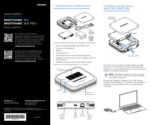
Per caricare la batteria, collegare il cavo USB al router mobile, quindi collegarlo a una presa a muro utilizzando l'adattatore di alimentazione CA o una porta USB del computer.Assicurarsi che l'orientamento della scheda nano SIM coincida con l'orientamento indicato sull'etichetta del dispositivo e inserirla delicatamente, quindi posizionare la batteria e il coperchio posteriore.NOTA: utilizzare solo le dita per inserire o rimuovere la scheda nano SIM. L'utilizzo di altri oggetti potrebbe danneggiare il dispositivo.1. COM'È FATTO IL DISPOSITIVO2. INSTALLAZIONE DELLA SIM E DELLA BATTERIAIl router mobile viene fornito con i seguenti componenti:• Router mobile Nighthawk® M6 o M6 Pro 5G*• Coperchio della batteria • Batteria• Cavo USB Tipo C• Alimentatore (varia in base all’area geografica)• Adattatori con presa Tipo C (per la maggior parte dei Paesi europei)•Adattatori con presa Tipo G (per il Regno Unito)*Illustrazioni del modello Nighthawk M6 per scopi illustrativi.antenna esterna (TS-9)antenna esterna (TS-9)USB Tipo CEthernetCONFORMITÀ NORMATIVA E NOTE LEGALIPer informazioni sulla conformità alle normative, compresala Dichiarazione di conformità UE, visitare il sito Web https:///it/about/regulatory/.Prima di collegare l'alimentazione, consultare il documento relativo alla conformità normativa.Può essere applicato solo ai dispositivi da 6 GHz: utilizzare il dispositivo solo in un ambiente al chiuso. L'utilizzo di dispositivi a 6 GHz è vietato su piattaforme petrolifere, automobili, treni, barche e aerei, tuttavia il suo utilizzo è consentito su aerei di grandi dimensioni quando volano sopra i 3000 metri di altezza. L'utilizzo di trasmettitori nella banda 5.925‑7.125 GHz è vietato per il controllo o le comunicazioni con sistemi aerei senza equipaggio.SUPPORTO E COMMUNITYDalla pagina del portale di amministrazione Web, fare clic sull'icona con i tre puntini nell'angolo in alto a destra per accedere ai file della guida e del supporto.Per ulteriori informazioni, visitare il sito netgear.it/support per accedere al manuale dell'utente completo e per scaricare gli aggiornamenti del firmware.È possibile trovare utili consigli anche nella Community NETGEAR, alla pagina /it.GESTIONE DELLE IMPOSTAZIONI TRAMITE L'APP NETGEAR MOBILEUtilizzare l'app NETGEAR Mobile per modificare il nome della rete Wi-Fi e la password. È possibile utilizzarla anche per riprodurre e condividere contenutimultimediali e accedere alle funzioni avanzate del router mobile.1. Accertarsi che il dispositivo mobile sia connesso a Internet.2. Eseguire la scansione del codice QR per scaricare l'appNETGEAR Mobile.Connessione con il nome e la password della rete Wi-Fi 1. Aprire il programma di gestione della rete Wi‑Fi deldispositivo.2. Individuare il nome della rete Wi‑Fi del router mobile(NTGR_XXXX) e stabilire una connessione.3. Only Connessione tramite EthernetPer prolungare la durata della batteria, l'opzione Ethernet è disattivata per impostazione predefinita. Per attivarla, toccare Power Manager (Risparmio energia) e passare a Performance Mode (Modalità performance).4. CONNESSIONE A INTERNETÈ possibile connettersi a Internet utilizzando il codice QR del router mobile da uno smartphone oppure selezionando manualmente il nome della rete Wi‑Fi del router e immettendo la password.Connessione tramite codice QR da uno smartphone 1. Toccare l'icona del codice QR sulla schermata inizialedello schermo LCD del router mobile.NOTA: quando è inattivo, lo schermo touch si oscura per risparmiare energia. Premere brevemente e rilasciare il pulsante di alimentazione per riattivare lo schermo.3. CONFIGURAZIONE DEL ROUTER MOBILETenere premuto il pulsante di accensione per due secondi, quindi seguire le istruzioni visualizzate sullo schermo per impostare un nome per la rete Wi‑Fi e una password univoci.La personalizzazione delle impostazioni Wi‑Fi consente di proteggere la rete Wi‑Fi del router mobile.Impostazioni APNIl router mobile legge i dati dalla scheda SIM e determina automaticamente le impostazioni APN (Access Point Name) corrette con i piani dati della maggior parte degli operatori. Tuttavia, se si utilizza un router mobile sbloccato con un operatore o un piano meno comune, potrebbe essere necessario immettere manualmente le impostazioni APN.Se viene visualizzata la schermata APN Setup Required (Configurazione APN richiesta), i dati APN dell’operatore non sono presenti nel nostro database ed è necessario inserirli manualmente. Immettere i valori fornitidall’operatore nei campi corrispondenti, quindi toccare Save (Salva) per completare la configurazione.NOTA: l’operatore determina le proprie informazioni APN e deve fornire le informazioni per il proprio piano dati. Si consiglia di contattare il proprio operatore per le impostazioni APN corrette e di utilizzare solo l’APN suggerito per il piano specifico.Schermata inizialeAl termine della configurazione, il router visualizza la schermata iniziale:Wi‑FiPotenza Carica Rete Codice QR connessione rapida Wi‑FiNome e Wi‑FiIcona del codice QR。

Jos tämä ensimmäinen Orbi-satelliitti, jonka lisäät Orbi-verkkoon, noudata näitä ohjeita:Aseta Orbi-satelliitti keskelle asuntoa, jotta saat parhaan WiFi-kantaman.Liitä Orbi-satelliitti virtalähteeseen. Orbi-satelliitin takana oleva virran merkkivalo syttyy vihreänä. Jos virran merkkivalo ei pala, paina virtapainiketta.2. Orbi-satelliitin paikka (jatkuu)Jos olet jo määrittänyt Orbi-reitittimen ja -satelliitin Orbi-verkkoosi, noudata näitä ohjeita:Aseta Orbi-satelliitti nurkkaan, joka on kaukana nykyisestä Orbi-reitittimestäja -satelliitista, mutta edelleen Orbi-reitittimen ja -satelliitin kantaman alueella.Jos asunnossasi on useita kerroksia, aseta Orbi-satelliitti eri kerrokseen kuin nykyinen Orbi-reititin ja -satelliitti.Liitä Orbi-satelliitti virtalähteeseen. Orbi-satelliitin takana oleva virran merkkivalosyttyy vihreänä. Jos virran merkkivalo ei pala, paina virtapainiketta.Orbi-reititin Orbi-satelliittiOrbi-reititinOrbi-satelliittiOrbi-satelliitti3. Orbi-satelliitin synkronointiOdota kaksi minuuttia, että Orbi-satelliitin rengasmerkkivalo palaa valkoisena. Paina sittenOrbi-satelliitin takapaneelin Sync (Synkronoi) -painiketta ja kahden minuutin kuluessaOrbi-reitittimen takapaneelin Sync (Synkronoi) -painiketta.Orbi-satelliitin rengasmerkkivalo syttyy valkoisena ja palaa sitten jonain seuraavista väreistäkolmen minuutin ajan ja sammuu:SininenOrbi-reititin ja -satelliitti on synkronoitu ja niiden välinen yhteys on hyvä.OranssiOrbi-reititin ja -satelliitti on synkronoitu ja niiden välinen yhteys on kohtalainen.Harkitse Orbi-satelliitin siirtämistä lähemmäs Orbi-reititintä.MagentaOrbi-reitittimen ja -satelliitin synkronointi epäonnistui. Siirrä satelliitti lähemmäsreititintä ja yritä uudelleen.Rengasmerkkivalo (ei näy kuvassa)Sync (Synkronoi) -painike (käytetään myös WPS-yhteyteen)Ethernet-portit USB-porttiPower On/Off -virtapainike ja virran merkkivalo DC-virtaliitäntäPalautuspainikeTukiKiitos, että hankit tämän NETGEAR-tuotteen. Osoitteessa /support voit rekisteröidä tuotteesi, hakea ohjeita, uusimpia latauksia ja käyttöoppaita ja liittyä yhteisöömme. Suosittelemme, että käytät ainoastaan virallisia NETGEAR-tukiresursseja.Nykyinen EU:n vaatimustenmukaisuusvakuutus on osoitteessa /app/answers/detail/a_id/11621/.Säännöstenmukaisuustiedot ovat osoitteessa /about/regulatory/.Tutustu säännöstenmukaisuustietoihin ennen virtalähteen liittämistä.NETGEAR INTL LTDBuilding 3, University Technology CentreCurraheen Road, Cork, IrelandNETGEAR, Inc.350 East Plumeria Drive San Jose, CA 95134, USA© NETGEAR, Inc., NETGEAR ja NETGEAR-logo ovat NETGEAR, Inc:n tavaramerkkejä. Muita kuin NETGEARin tavaramerkkejä käytetään vain viittaustarkoituksessa.Lokakuu 2016Valmista!Orbi-satelliitti (malli RBS50)Virtasovitin(vaihtelee alueittain)213421567。

(中国区)德国伊文捷琳(香港)化妆品集团公司Germany Evangeline(Hong Kong)Cosmetic Group Company德國伊文捷琳(香港)化妝品集團公司Germany Evangeline (HongKong) Cosmetic Group Company香港九龍旺角彌敦道678號華僑商業中心15cUnit c,15/F Hua Chiao Comm Ctr678 Nathan RD Mongkok Kowloon HongKong广州市璩可商贸有限公司Guangzhou Quke Commerce & Trading Co,Ltd.广州市番禺区洛溪新城裕景花园西区三街五号PC:511431Number 5,Street 3,Yujing Garden Apartment,Luoxi new city,Panyu,Guangzhou Tel:(020)8458 9510 6238 3371 Fax:(020) 8458 9510蕴繁于简效果卓越研发严谨Evangeline伊文捷琳品牌简述●品牌创始人Evangeline伊文捷琳品牌创办人Schuhmacher舒马赫是一位生化学家,他是生于德国拥有着德国贵族血统的希腊籍后裔,出生于六十年代中期的舒马赫从小就天赋秉异,聪明过人,博古通今,教育良好,对于王室的尊贵奢华醉心迷离,对于家族的荣光眷恋不舍,所以年轻时代的舒马赫活力四射,魅力翩翩。
由于家族显赫的缘故,Schuhmacher舒马赫从小就接触到一些高档奢侈品,从奔驰老爷车到母亲梳妆台前的化妆品,慢慢对这些“让人青春永驻”的瓶瓶罐罐感兴趣。
舒马赫开始把生化科技与美容关联起来,就读于德国慕尼黑大学。
因成绩优异,曾获德国洪堡研究奖学金助资。
期间曾受教于德国著名生化学家迈而霍夫(Meyerhof),在生化领域取得一系列优异的科研成果。
●品牌核心技术优势(IHS)1982年在家族的帮助下成立了德国Schuhmacher皮肤护理研究所。

发布日期: 04-五月-2020修订日期 20-一月-2023SDS 编号: 15531产品名称: Ellamera PER-SUST™ 804, 聚合物版本号: 3.0化学品安全技术说明书按照GB/T 163483、GB/T 17519编制。
第1部分 化学品及企业标识Ellamera PER-SUST™ 804, 聚合物化学品中文名Ellamera PER-SUST™ 804化学品英文名制造商或供应商美国总部名称Kraton Corporation地址15710 John F Kennedy Blvd., Suite 300Houston, TX 77032, 美国电话号码+1 281 504 4700中国名称科腾聚合物贸易(上海)有限公司地址南京西路688号22楼2201室中国上海市静安区,邮编200041电话号码+86 21 20823888Technical Support Line -International+1 800 4 Kraton (572866) ; +1 281 504 4950Technical Support Line -EU +31 (0) 36 546 2800网站EMERGENCY RESPONSE NUMBERS:美国化学品运输紧急应变中心(CHEMTREC):+1 703 527 3887SGS Ewacs NV:+32 35 75 5555推荐用途及限制用途化妆品和个人护理产品中的一种成分。
推荐用途04-五月-2020发布日期20-一月-2023修订日期03-五月-2022更新日期15531SDS 编号第2部分 危险性概述紧急情况概述GHS 危险性类别未分类。
标签要素无。
象形图警示词无。
危险性说明不适用。
防范说明预防措施不适用。
事故响应不适用。
安全储存不适用。
废弃处置不适用。
本品在正常的使用、储存和运输条件下,性能稳定,不起反应。
物理和化学危险无资料。
健康危害无资料。
![意大利督凯提中、高[1][1].低电容器技术说明(中)](https://img.taocdn.com/s1/m/d6c327e1524de518964b7d19.png)
中、高压电容器技术要求1. 国际知名品牌,原装进口元件;具备ISO9001同品牌认证;2. 采用无毒、可生物降解的有机油填充,具备稳定的电气性能;3. 绝缘瓷套管与金属外壳采用金属涂敷(焊接方式),具有完美的密封性,不漏油;外观无缝连接;4. 金属外壳为柔性钢壳,可以补偿内部绝缘油体积的变化,并防止辐射和磁涡流;5. 电容偏差:-5% ∽ + 10%;6. 电容器平均损耗< 0.01%(<0.1w/kvar);7. 内置放电电阻,断电后5分钟内将残余电压降至50V以下;8. 具备ISO9001认证,认证同产品名称;9. 最大峰值暂态电流:100In,最大允许过电流Imax≤1.3In;10. 可选择的电容器元件的保护方式:外附熔丝/内附熔丝,标准配置外附式熔丝,避免内附熔丝导致的由于容量变化而使谐振点偏移;11.低温局放:在温度范围下限值时的局部放电熄灭电压不低于1.15Un;12.外壳耐爆能力:≥12KJ13.电容器引出端子的套管能承受≥980N 的水平拉力14.电容器应具备ISO9001 认证,电容器交货后提供原厂试验报告。
低压电容器技术协议部分内容:1.电容器必须是额定电压525V,50Hz,的三相金属化聚丙烯膜。
2.电容器的电流过载能力:4In3.电容器选用外置式熔丝。
4.电抗器的电流过载能力:1.8In5.电抗器的级别是H级,有温度保护功能(170℃即动作)。
6.电容器寿命在20万小时以上。
7.电容器的介质损耗小于:0.2W/Kvar8.放电电阻要在60秒时间内,50V以下。
9.电容器的投切涌流耐受能力:200In10.功率因数控制器必须有谐波过载保护功能。
11.产品必须欧美原装进口,具有ISO9001认证。
12.符合IEC-831-1,IEC831-2等标准。
13.电抗率为7%。

*This SDS for user in China - Not correspond to the regulation of other regions.梯希爱(上海)化成工业发展有限公司修订日期修订日期:: 08/08/2021化学品安全技术说明书修改号码修改号码:: 2.1修订日期修订日期:: 08/08/2021Page 1 of 32. 危险性概述G H S 分类物理性危害未分类 健康危害未分类 环境危害未分类 G H S 标签元素图标或危害标志无 信号词无信号词 危险描述无 防范说明无1. 化学品及企业标识产品名称产品名称::乙基甾烯二酮T C I 产品编码产品编码::E0921公司:梯希爱(上海)化成工业发展有限公司地址:上海化学工业区普工路96号部门:营业部电话号码:************传真号码:************e-mail:*************************应急电话应急电话::*************修改号码修改号码::2.13. 成分/组成信息单一物质/混合物单一物质化学名(中文名):乙基甾烯二酮百分比百分比::>98.0%(HPLC)CAS RN :21800-83-9俗名俗名::18-Methylestr-4-en-3,17-dione 分子式分子式::C 19H 26O 24. 急救措施吸入吸入::将受害者移到新鲜空气处,保持呼吸通畅,休息。
若感不适请求医/就诊。
皮肤接触皮肤接触::立即去除/脱掉所有被污染的衣物。
用水清洗皮肤/淋浴。
若皮肤刺激或发生皮疹:求医/就诊。
眼睛接触眼睛接触::用水小心清洗几分钟。
如果方便,易操作,摘除隐形眼镜。
继续清洗。
如果眼睛刺激:求医/就诊。
食入食入::若感不适,求医/就诊。
漱口。
紧急救助者的防护紧急救助者的防护::救援者需要穿戴个人防护用品,比如橡胶手套和气密性护目镜。
梯希爱(上海)化成工业发展有限公司修改号码修改号码:: 2.1修订日期修订日期::08/08/2021Page 2 of 3 5.消防措施合适的灭火剂合适的灭火剂::干粉,泡沫,雾状水,二氧化碳特定方法特定方法::从上风处灭火,根据周围环境选择合适的灭火方法。

Helmet & Bike Kit Quick Start Guide✓ ion’s versatile CamLOCK System allows you to attach the ion camera to any type of helmet (bike, motorcycle, ski, skydive etc.)✓ Mount the camera onto the handlebar of bicycles, jet skis, 4x4 ATVs and motorcycles, as well as ski poles. ✓ The CamLOCK system allows you to easily remove and remount the camera.✓ The ball joint is designed to allow the user to turn the camera to capture multiple views (front, side, back, etc.), without remounting the camera.1. Getting to Know Your Mount SystemCamLOCK 12345678910Mount or remove the camera quickly from the CamLOCK socket.Ball Joint - Short Attach CamLOCK. Ball joint - L shape Attach CamLOCK.Secure Strap Secure the camera to the mount to provide additional security.Helmet Mount Mount the camera on different type of helmets.Removable Ball Joint Nut – To tighten and loosen the ball joint.Fitting Piece Work with Helmet Mount to provide additional security for the mount system.Mount strap - short Loop through the helmet mount, fitting piece and helmet. Mount strap - medium Loop through the helmet mount, fitting piece and helmet.Single and Double Sided 3M Adhesive Mounts Adhere to the helmet mount, fitting piece or helmet.Bike MountAttach the Air Pro camera to handlebars, ski poles and more. Fit 0.75” to 1.4” (20 - 35mm) diameter tubes.Removable Ball Joint Nut –Tighten and loosen the ball joint. Bike Mount Screws – Tighten and loosen the bike mount.2. Before Mounting Your Camera3. Getting Started2.1 Secure Strap1. Loop one end of the secure strap through the strap hole of the camera. You may use a pin to help thread it thru the hole.2. Attach other half to the mount3. Clip both ends together when camera is mounted.2.2 CamLOCK1. Fit the screw of the CamLOCK to the tripod socket of the camera.2. Screw the CamLOCK until it is tightened on the camera.1. Choose the suitable strap to mount on different types of helmets. . For example, use the short mount strap for bike helmets and the medium mount strap for motorcycle helmets.2. Remove the 2 strap clips from the strap.3. There are three vents at each side of the Helmet mount. Loop the strap through the inner vent (closest to the center) from the bottom. (Step 1)4. Loop the strap through the strap clip from the top. (Step 2)5. Loop the strap through middle vent from the top. (Step 3)6. Loop the strap through the outer vent from the bottom (Step 4)7. Tighten the strap and repeat Step 1 – 4 on the other side.3.1 Connecting Your Camera to a PC4. Trademark Information3.2 Mounting on your Bike Helmet3.3 Mounting on your Motorcycle Helmet3.4 Mounting on the Handlebar or Pole1. Choose the Helmet Mount with the suitable length of strap.2. Adhere the single sided 3M adhesive mount to the base of the helmet mount. Use the double sided 3M adhesive mount to permanently secure the mount to the helmet.3. Loosen and detach the ball joint nut from the helmet mount.4. Install the ball joint to the helmet mount and tighten the nut.5. Loop the strap of the helmet mount through the vents of the bike helmet and back through the strap clip.6. Fasten the strap.7. Repeat on the opposite end of the strap until the helmet mount is firmly attached to the helmet.8. Attach the CamLOCK and camera into the CamLOCK socket. Ensure that the CamLOCK nut is tightened securely. For EU only Questions?Need Some Help?This manual should help you understand your new product.If you still have questions, visit our website:Like Us:/iontheaction Tweet Us:/iontheactionENGetting to Know Your CamLOCK System and Helmet & Bike AccessoriesNote:The CamLOCK system allows the user to change the angle of the camera. Simply loosen the nut, adjust the camera angle and re-tighten the nut.1. Adhere the helmet mount to the helmet by applying a double-sided 3M adhesive mount.. By utilizing a combination of the helmet mount and fitting piece, it will provide additional security to the mount system.2. Select the Helmet Mount with suitable length of strap.3. Loosen and detach the ball joint nut from the helmet mount.4. Install the L ball joint to the helmet mount and tighten the nut.5. Adhere the double sided 3M adhesive mount to the base of the helmet mount and fitting piece.6. Attach the helmet mount at one side of the helmet.7. Loop the strap to another side of helmet, through the vent of fitting piece and back to the original side of the helmet. 8. Fasten the strap with strap clip.9. Repeat on the opposite end of the strap until the helmet mount is firmly attached to the helmet.10. Attach the CamLOCK and camera to the CamLOCK socket. Assure that the CamLOCK nut is tightened securely. Note:The CamLOCK system allows the user to make simple changes to the angle the camera is positioned. Simply loosen the nut, adjust the camera angle, and re-tighten the nut.1. Loosen both bike mount screws.2. Attach the bike mount to the handlebar or pole and tighten the screws until the mount is firmly secured.3. Loosen and detach the ball joint nut from the bike mount.4. Insert the ball joint into the CamLOCK socket and tighten the nut.5. Attach the CamLOCK and camera into the CamLOCK socket. Assure that the CamLOCK nut is tightened securely.Note:The CamLOCK system allows the user to make simple changes to the angle the camera is positioned. Simply loosen the nut, adjust the camera angle, and re-tighten the nut.© 2012 World Wide Licenses Limited.® The ion logo is a registered trademark of World Wide Licenses Limited.CamLOCK, PODZ, Shoot/Share and AIR PRO and their respective logos are trademarks or registered trademarksof World Wide Licenses Limited in the United States and other countries. Copyright © 2012. All Rights Reserved.Helm & Bike Kit✓ ion’s universelles CamLOCK System ermöglicht es Ihnen die ion Kamera an alle Helmtypen (Rad, Motorrad, Ski, Fallschirm, , u.s.w.) zu befestigen✓ Befestigen Sie die Kamera an die Lenkstange von Rädern, Jet-Skis, Quads, ATVs und Motorrädern als auch an Skistangen✓ Das CamLOCK Ssystem ermöglicht es Ihnen die Kamera einfach abzubauen und einfacst wieder zu installieren.✓ Das Kugellager System is so Konzipiert um den Benutzer die Kamera zu drehen und aus unterschiedlichsten Ansichten (Frontal. Seitlich, Rückwärts u.s.w.) zu filmen, ohne die Kamera ab- oder umbauen zu müssen.1. Getting to Know Your Mount SystemCamLOCK 12345678910Schnell-Befestigung für ion-Kamera mit CamLOCK Fassung Kugelgelenk - Kurz Verbindung zu CamLOCK.Kugelgelenk - L Form Verbindung zu CamLOCK.Sicherheitsband Sicherheitsband um die Kamera noch zusätzlich an der Befestigung zu befestigen.Helm Befestigung Um die Kamera auf die verschiedensten Helm-Typen zu befestigen.Wechselbare Führungsgelenk Mutter – Um das Kugellager festzuschrauben – oder zu lösen. Pass TeilDient bei der Helm-Befestigung um zusätzliche Sicherung für das Befestigungssystem zu geben.Befestigungsband - KurzBefestigungsband um dieses durch die Helmbefestigung und das Passteil durchzuführen.Befestigungsband - Medium Befestigungsband um dieses durch die Helmbefestigung und das Passteil durchzuführen.Ein - und Zweiseitiges 3M Selbstklebe Befestigungs-Pass TeileSelbstklebende Elemeite für den Helm-KitBike Befestigung Befestigung für die Air Pro camera an die RadGabel, Slalom oder Schistangen und vieles mehr. Passform für Röhrendurchmesser von. Fit 0.75” to 1.4” (20 - 35mm)Abnehmbare Kugellager-Halterung Fixieren und Lösen des Kugellagers.Bike –Befestigungs-Schrauben – Fixieren und Lösen der Bike-Befestigung2. Bevor Sie die Kamera Montieren3. Bereitmachen2.1 Sicherheits Band1. Führen Sie ein Ende des Sicherheitsbandes durch dieBand-Öffnung an der Unterseite. Eine Stecknadel könnte bei der Einfädelung hilfreich sein.2. Befestigen Sie die andere Hälfte des Bandes an der entsprechenden Befestigung3. Klippen Sie beide Enden des Bandes zusammen, nachdem die Kamera motiert wurde2.2 CamLOCK1. Verschrauben Sie die Schraube des CamLOCK mit dem Tripod.2. Schrauben Sie den CamLOCK soweit fest bis die Kamera fest befestigt ist.1. Wählen Sie die Helm-Befestigung mit der geeignetenBefestigungsbandlänge, die am Besten für Ihren Helm geeignet ist.z.B.das kurze Befestiungsband für Bike Helme und das Mittelgrosse Band für Motorradhelme2. Entfernen Sie die beiden Clips vom Band3. mounts gibt 3 Öffnungen an jeder Seite der Helm-Befestigung. Fädeln Sie das Band von unten durch die Innerste Öffnung (am Nähesten zur Mitte) der Helmbefestungung (Schritt 1).4. Fädeln Sie die das Band von Oben durch einen der Befestigungs Clips (Schritt 2)5. Fädeln Sie nun von Oben das Band durch die mittlere Öffnung (Schritt 3)6. Fädeln Sie das Befestigungsband von der Unterseite durch die äußerste Öffnung der Helmbefestigung (Schritt 4)7. Ziehen Sie das Band straff und .wiederholen Sie Schritt 1 bis Schritt 4 auf der anderen Seite der Helmbefestigung3.1 Befestigung Ihrer Helmbefestigung mit dem Sicherheitsband3.2 Befestigung Ihres Bike Helm zu3.3 Befestigung am Motorrad Helm3.4 Befestigen an der Gabel oder an einer Stange1. Wählen Sie die Helm-Befestigung mit der geeignetenBefestigungsbandlänge, die am Besten für Ihren Helm geeignet ist.2. Kleben sie das einseitigen 3M Klebe-Passteil an der Basis der Helmbefestigung. Verwenden Sie das Zwei-seitige 3MKlebe-Passteil um die Befestigung permanent an den Helm zu befestigen.3. Lockern und Trennen Sie das Kugelgelenk von der Helm-Befestigung.4. Befestigen Sie das Kugelgelenk an der Helm-Befestigung und ziehen Sie die Mutter fest an.5. Führen Sie das Befestigungsband durch die Lüftungsschlitze des Helms und durch die Band-Schlitze der Helmbefestigung.6. Zurren Sie das Band fest7. Führen Sie das andere .Ende des Bandes wie unter Punkt 5 und 6 beschrieben durch den Helm und die Helmbefestigung.8. Pressen Sie die CamLOCK und die Kamera in die CamLOCK Halterung. Stellen Sie sicher dass die CamLOCK Mutter fest und sicher angezogen ist.For EU onlyFragen?Sie brauchen zusätzliche Hilfe?Dieses Bedienhandbuch sollte Sie bei Ihren Fragen unterstützen.Sollten Sie weitere Fragen haben, visit our website:Like Us:/iontheaction Tweet Us:/iontheactionDELernen Sie Ihr CamLOCK System und das Zubehör für Helm & Bike kennenAnmerkung:Das CamLOCK system erlaubt dem Anwender die Kamera unter verschiedensten Winkeln zu verwenden. Durch einfaches Lösen der Verschraubung kann die Kamera adjustiert werden, und danach durch einfaches festziehen Dieser wieder fixiert werden.1. Befestige die Helm-Befestigung unter Benutzung der Zwei-Seitigen 3M Selbstklebe-Pass Teile.Unter Verwendung der Kombination der Helm-Befestigung und der Pass-Teile ergibt sich eine zusätzliche Sicherheit des Befestigungssystems.2. Wählen Sie das entsprechende Befestigungssysteme und die geeignete Länge des Befestigungsbandes.3. Lockern und Trennen Sie das Kugelgelenk von der Helm-Befestigung.4. Befestigen Sie das Lmit der Helm-Befestigung und ziehen Sie die Mutter fest an.5. Befestige das zwei seitige 3M Klebe Befestigungs Pass TEil an der Basis des Helmes und dem Pass Teil:6. Bestegen Sie diese an einer Seite des Helmes7. Führen Sie das Band auf die andere Seite des Helmes, führen Sie dieses durch die Öffnung des Pass-Teiles und zurück auf die andere Seite des Helms1. Lösen Sie beide Schrauben der Radbefestigung2. Befestigen Sie die Radbefestigung an der Gabel oder einer Stange und ziehen Sie die Schrauben fest an.3. Lösen und Trennen Sie den Passteil des Kugelgelenks der Radbefestigung4. Pressen Sie die CamLOCK und die Kamera in die CamLOCK Halterung. Stellen Sie sicher dass die CamLOCK Mutter fest und sicher angezogen ist5. Attach the CamLOCK and camera into the CamLOCK socket. Assure that the CamLOCK nut is tightened securely. Note:Das CamLOCK system erlaubt dem Anwender die Kamera unter verschiedensten Winkeln zu verwenden. Durch einfaches Lösen der Verschraubung kann die Kamera adjustiert werden, und danach durch einfaches festziehenDieser wieder fixiert werden.Anmerkung:Das CamLOCK system erlaubt dem Anwender die Kamera unter verschiedensten Winkeln zu verwenden. Durch einfaches Lösen der Verschraubung kann die Kamera adjustiert werden, und danach durch einfaches festziehen Dieser wieder fixiert werden.Kit Casque & Vélo Guide de démarrage✓ Le système de verrouillage flexible CamLOCK permet d'attacher la caméra AIR PRO à tout type de casque (vélo, moto, ski, casque pour saut en parachute, etc.)✓ La caméra peut être fixée au guidon de vélos, jet skis, quads, motos et bâtons de ski.✓ Le système CamLOCK permet la fixation et le retrait facile de la caméra.✓ Le support articulé (système à billes) permet l'orientation de caméra pour obtenir de multiples points de vue (avant, arrière, côtés, etc.), sans avoir à démonter et remonter la caméra.1. Connaître votre système de montageCamLOCK 12345678910Pour monter ou démonter la caméra rapidement de la fixation CamLOCK.Articulation à bille - Courte Pour attacher le CamLOCK Articulation à bille - En L Pour attacher le CamLOCK Dragonne Pour sécuriser la caméra en l’attachant au support.Support de casque Fixe la caméra à différents types de casques.Écrou amovible de l’articulation à bille - pour serrer ou desserrer l'articulation et régler l’inclinaison du casquePièce d’encrage Permet d’attacher le support à différents types de casques.Sangle d'attache du support - Courte Fixation entre le support de casque, la pièce d'attache et le casque. Sangle d'attache du support - Moyenne Fixation entre le support de casque , la pièce d'attache et le casque.Bandes adhésives 3M simple et double face.Assure l'adhésion entre le support de casque, la pièce d’encrage et le casque.Support de guidonPour fixer Air Pro à des guidons, bâtons de ski et plus encore. Adapté à des tubes de diamètre 0.75” à 1.4” (20 - 35mm).Écrou amovible d'articulation à bille - pour serrer ou desserrer l'articulation Vis de support de guidon - pour serrer ou desserrer le support de guidon2. Avant de monter votre caméra3. Démarrer2.1 Fixer la sangle d'attache1. Faites passez une extrémité de la dragonne dans l'œillet de la caméra. Vous pouvez vous aider d'une aiguille pour y parvenir plus facilement.2. Fixez l'autre extrémité au support.3. Clipsez les deux extrémités ensemble lorsque la caméra est fixée.2.2 CamLOCK1. Placez la vis du CamLOCK dans le trépied de support de la caméra.2. Vissez le CamLOCK jusqu'à fixation complète à la caméra.1. Choisissez la sangle d'attache adaptée au type du casque. Par exemple, choisissez la sangle d'attache courte pour les casques de vélo et la dragonne moyenne pour un casque de moto.2. Retirez les deux clips de la sangle d’attache3. Le support de casque possède 3 fentes sur ses côtés. Faites passer la sangle d'attache dans la fente intérieure (la plus proche du centre), en commençant par le bas. (Étape 1)4. Faites passer la sangle d'attache dans le clip en commençant par le haut. (Étape 2)5. Faites passer la sangle d'attache dans la fente du milieu en commençant par le haut. (Étape 3)6. Faites passer la sangle d'attache dans la fente extérieure en commençant par le bas (Étape 4).7. Serrez la sangle d'attache et répétez les étapes 1 – 4 de l'autre côté.3.1 Installer votre support de casque avec la sangle d'attache4. Informations légales3.2 Monter le support sur votre casque de vélo3.3 Monter le support sur votre casque de moto3.4 Fixation à un guidon ou à un bâtonFor EU only Des questions ?Besoin d'aide ?Ce guide vous aidera à comprendre votre nouveau produitSi vous avez toujours des questions,visitez notre site web : Aimez nous :/iontheaction Twittez nous :/iontheactionFRConnaître votre système CamLOCK et accessoires pour Casque & VéloRemarque:Le système CamLOCK permet d’orienter aisément la caméra. Desserrez simplement l'écrou de fixation, ajustez l'angle de la caméra puis resserrez l'écrou.Remarque:Le système CamLOCK permet d’orienter aisément la caméra. Desserrez simplement l'écrou de fixation, ajustez l'angle de la caméra puis resserrez l'écrou.1. Desserrez les deux vis de support de guidon.2. Attachez le support au guidon ou bâton puis serrez les vis jusqu'à fixation complète.3. Desserrez et retirer l'écrou de l'articulation à bille du support de guidon.4. Installez l'articulation à bille sur la fixation CamLOCK et serrez l'écrou.5. Attachez l'ensemble CamLOCK et caméra sur la fixation CamLOCK. Assurez-vous que l'écrou CamLOCK est correctement serré. Remarque:Le système CamLOCK permet d’orienter aisément la caméra. Desserrez simplement l'écrou de fixation, ajustez l'angle de la caméra puis resserrez l'écrou.© 2012 World Wide Licenses Limited.® Le logo ion est une marque déposée de World Wide Licenses Limited.CamLOCK, PODZ, Shoot/Share et AIR PRO ainsi que leurs logos respectifs sont des marques ou marquesdéposées de World Wide Licenses Limited aux États-Unis et autres pays. Copyright © 2012. Tous droits réservés.1. Choisissez le support de casque équipé de la longueur de sangle d'attache adaptée.2. Collez la bande d'adhésif 3M simple face à la base de la monture de casque.Utilisez la bande d'adhésif 3M double face pour fixer la monture de manière permanente3. Desserrez et retirer l'écrou de l'articulation à bille du support de casque.4. Installez l'articulation à bille sur le support de casque et serrez l'écrou.5. Faites passez la sangle d'attache par les fentes d'aération du casque de vélo et dans le clip d'attache.6. Serrez la sangle d'attache.7. Répétez l'opération avec l'autre extrémité de la sangle d'attache jusqu'à fixation totale du support.8. Attachez l'ensemble CamLOCK et caméra sur la fixation CamLOCK. Assurez-vous que l'écrou CamLOCK est correctement serré. 1. Attachez le support au casque à l'aide de l'adhésif 3M double face. En combinaison avec la pièce d’encrage, ceci assurera une fixation maximum.2. Choisissez le support de casque équipé de la longueur de sangle d'attache adaptée.3. Desserrez et retirer l'écrou de l'articulation à bille du support de casque.4. Installez l'articulation en L sur le support de casque et serrez l'écrou.5. Collez la bande d'adhésif 3M double face à la base du support de casque et de la pièce d'attache.6. Attachez le support de casque sur un côté du casque.7. Faites passer la sangle d'attache de l'autre côté du casque, au travers de la fente de la pièce d'encrage et de nouveau sur le point de départ. 8. Fixez la sangle d'attache à l'aide du clip.9. Répétez l'opération avec l'autre extrémité de la sangle d'attache jusqu'à fixation totale du support.10. Attachez l'ensemble CamLOCK et caméra sur la fixation CamLOCK. Assurez-vous que l'écrou CamLOCK est correctement serré. Kit per Casco e BiciclettaGuida Rapida✓ Il sistema CamLOCK studiato per la tua ION è molto versatile e ti consente di fissare la tua fotocamera ad ogni tipo di casco,bicicletta,motocicletta,etc.✓ Montare la tua ION sul manubrio della bicicletta, della motocicletta,della moto d’acqua,del furistrada, sulle racchette da sci è veramente molto semplice✓ Il sistema CamLOCK ti consente di montare e smontare la tua fotocamera in modo semplice e rapido.✓ Il sistema di aggancio sferico è progettato per consentire all'utente di catturare immagini e video da ogni angolazione e posizione (frontale, laterale, posteriore, ecc), senza smontare la fotocamera.1. Conoscere i sistemi di montaggioCamLOCK12345678910Utile a fissure la ion su ogni supporto Sfera di aggancio -Corta Utile ad agganciare la CamLOCK Sfera di aggancio –Lunga Utile ad agganciare la CamLOCKCinghia di sicurezza Cinghia per ion utile per una sicurezza maggiore Montaggio Casco Utile a fissare la ion su ogni tipo di Casco.AdattatoreUtile ad offrire una maggiore sicurezza nel fissaggio del Casco.Cinghia di montaggio-CortaUtile a fissare il Casco con l’ausilio dell’adattatore.Cinghia di montaggio-Corta Utile a fissare il Casco con l’ausilio dell’adattatore.Adesivo singolo e doppioUtile ad assicurare un maggiore fissaggio al Casco Sistema di fissaggio al manubrio della biciclettaUtile a fissare la ion al manubrio della bicicletta e non solo. Diamentro manubrio da 20 a 35 mm.2. Prima di montare la tua ion3. Guida Introduttiva2.1 Cinghia di Sicurezza1. Agganciare un’estremità della cinghia alla ion.2. Agganciare l’altra estremita della cinghia al gancio posto alla base della CamLOCK (vedi imagine 2).3. Unire le due estremità.2.2 CamLOCK1. Avvitare la vite della CamLOCK nell’apposita filettatura posta alla base della ion.2. Assicurarsi che la vite della CamLOCK sia stata serrata in modo corretto.1. Scegliere la cinghia più adatta a montare i differenti tipi di casco. Un esempio: usare la cinghia corta per I caschi da bicicletta e quella media per I caschi da motocicletta.2. Rimuovere la clips 2 dalla cinghia.3. Ci sono 3 prese d’aria su ogni casco. Avvolgere la cinghia in queste fessure (Step 1)4. Avvolgere la cinghia alla clip ed al lato alto del casco (Step 2).5. Avvolgere il cinturino attraverso la presa di mezzo partendo dalla parte superiore. (Fase 3)6. Avvolgere il cinturino attraverso la presa più esterna partendo dalla parte inferiore (Fase 4)7. Stringere il cinturino e ripetere le Fasi da 1 a 4 sull’altro lato.3.1 Installare l’attacco per elmetto con il cinturino4. Trademark Information3.2 Montare la ion al casco della bicicletta3.3 Montaggio sull’elmetto per moto3.4 Montaggio sul manubrio o sulla racchetta1. Scegliere la cinghia la cui lunghezza sia adatta al casco.2. Utilizzare l’adesivo 3M per fissare in modo definitivo il supporto al casco.3. Allentare o rimuovere la sfera di aggancio dal casco.4. Installare la sfera di aggancio e serrare il dado.5. Passare la cinghia attraverso la fessura del casco ed agganciarla alla clip.6. Fissare la cinghia .7. Ripetere la stessa operazione anche sul lato opposto e fissure saldamente il support al casco.8. Agganciare la CamLOCK e la ion al supporto .Assicurarsi che la CamLOCK e’ fissata con sicurezza.For EU onlyDomande?Hai bisogno di aiuto?Questo manual potrebbe aiutare te a comprendereSe hai alter domande chiama oppure visita il sito /iontheaction/iontheactionITConoscere il tuo sistema CamLOCK come accessorio per il casco e la bicicletta.Note:La CamLOCK consente di poter riprendere immagini con ogni angolazione. Basta allentare il dado, regolare la ION e serrare di nuovo il dado.1. Incollare il doppio adesivo 3M su un lato del casco.2. Selezionare la cinghia piu’adatta al casco.3. Allentare o rimuovere la sfera di aggancio dal casco.4. Montare la sfera di aggancio lunga al casco e serrare il dado.5. incollare l’ adesivo 3M sul lato opposto alla ion ed incollare l’adattatore.6. Attaccare il support ion ad un lato del casco.7. Avvolgere la cinghia al casco passandola attraverso il supporto ion e l’adattatore.8. Fissare bene la cinghia.9. Ripetere l’operazione anche sul lato posterior del casco, fissure la cinghia su entrambi i lati.10. Introdurre la CamLOCK e la ion al supporto ed assicurarsi che l’operazione sia riuscita.Nota:Il sistema CamLOCK consente all’utente di apportare semplici modifiche all’angolazione in cui la fotocamera è posizionata. È sufficiente allentare il dado, regolare l’angolo della fotocamera e serrare nuovamente il dado1. Allentare entrambe le viti del supporto.2. Montare il supporto per la bicicletta al manubrio e serrare Ie viti fino ad ottere un fissaggio sicuro.3. Allentare o rimuovere la sfera di aggancio.4. Inserire il supporto nella CamLOCK.5. Agganciare la ION alla CamLOCK ed assicurarsi che l’operazione sia avvenuta in modo corretto.Nota:Il sistema CamLOCK consente all’utente di apportare semplici modifiche all’angolazione in cui la fotocamera è posizionata. È sufficiente allentare il dado, regolare l’angolo della fotocamera e serrare nuovamente il dado.© 2012 World Wide Licenses Limited.® Il logo ION e’ stato registrato dalla World Wide Licenses Limited.CamLOCK, PODZ, Shoot/Share and AIR PRO sono loghi registrati dalla World Wide Licenses Limited in tutto ilMondo Copyright © 2012. Tutti I diritti sono riservati.头盔和脚踏车系列快速入门指南✓ ion 的通用主机连接卡扣组件系统允许你固定ion 相机至任何类型的头盔上。

Name and function of each partName und Funktion des jeweiligen TeilsNom et fonction de chaque pièceNombres y funciones de cada parteNome e funzione di ciascun componenteHeadsetManualENGLISHSpecificationsHow to connectBasic operation instructionsConnect the USB connecter (USB A) to the PC USB B cable USB connector (USB A)Adjusting the volumeVolume up Turning off the microphone (Mute mic)Mute micTurning off the noise reduction functionTurn offthe noise reductionfunctionWhen OFF:the light will blink twice.This function may not be available, depending on the connected device or application. This function may not be available, depending on the connected device or application.If the mic mute function does not work on this product, try operating the mute function from your software or application.Volume down When mic is ON: (Blue) lights up When mic is OFF: (Red) lights upCompatible models PC equipped with USB-A terminal, PlayStation 4/5 andNINTENDO SWITCH™.Functions cannot be guaranteed for all devices.External dimensions (W x D x H)Approx. 180 × 70 × 190mm [7.1" × 2.8" × 7.5"] (excluding cable)When folded: Approx. 180 × 70 × 120mm [7.1" × 2.8" × 4.7"] (excluding cable)Cable length Approx. 1.9m [6.2ft]Weight Approx. 165g [5.8oz] (excluding cable)HeadsetSpeaker type Dynamic type (monaural)Driver unitDiameter 40mm Maximum input 20mW Impedance100 ΩFrequency response20 to 20,000HzMicrophoneMicrophone type Electret condenser Directionality Unidirectional HeadsetBedienungsanleitungTechnische DatenSo funktioniert das AnschließenHinweise zur grundlegenden BedienungUSB-Stecker (USB A) an die USB-Buchse des PCs anschließen.USB-Kabel USB-Stecker (USB A)Lautstärke einstellenLautstärke erhöhenAusschalten des Mikrofons (Mikrofon stummschalten)Mikrofon stummschaltenAusschalten RauschunterdrückungsfunktionBei OFF:Leuchte blinkt zweimal.Je nach angeschlossenem Gerät oder Anwendung ist diese Funktion möglicherweise nicht verfügbar. Sollte die Mikrofonstummschaltung bei diesem Produkt nicht funktionieren, schalten Sie die Stummschaltung mithilfe Ihrer Software oder Anwendung utstärke reduzierenBei Mikrofon ON: (Blau) leuchtet auf Bei Mikrofon OFF: (Rot) leuchtet aufOreilletteManuelSpécificationsComment la connecterInstructions d'utilisation de baseConnectez le connecteur USB (USB A) au port USB du PC.Câble USB Connecteur USB (USB A)Réglage du volumeAugmentation du volumeDésactivation du micro (Mise en sourdine du micro)Mise en sourdine du microLorsque le micro est activé (ON) : (Bleu) s'allumeLorsque le micro est éteint (OFF) : (Rouge) s'allumeDésactivation de la fonction de réduction du bruitDésactiver la fonction de réduction du bruitLorsqu'il est éteint (OFF) : le voyant clignote deux fois.Cette fonction peut ne pas être disponible, selon le dispositif ou l'application connecté(e). Cette fonction peut ne pas être disponible, selon le dispositif ou l'application connecté(e).Si la fonction de mise en sourdine du micro ne fonctionne pas sur ce produit, essayez d'utiliserladite fonction à partir de votre logiciel ou application.Baisse du volumeAuricularesManualEspecificacionesComo se conectaInstrucciones básicas de funcionamientoConecte el conector USB (USB A) al puerto USB del PC.Cable USB Conector USB (USB A)Ajuste del volumenSubir el volumenApagar el micrófono (Silenciar micrófono)Silenciar micrófonoDesactivación de la función de reducción de ruidoDesactivar la función de reducción de ruidoCuando se apague:la luz parpadeará dos veces.Es posible que esta función no se encuentre disponible según el dispositivo o la aplicación conectados. Si la función silenciar micrófono no funciona en este producto, intente activar la función silenciar desde su software o aplicación.Bajar el volumenCuando se enciende el micrófono: (Azul) se iluminaCuando se apaga el micrófono: (Rojo) se iluminaCuffiaManualeSpecificheCome eseguire il collegamentoIstruzioni di base per l’usoCollegare il connettore USB (USB A) alla porta USB del PC.Cavo USBConnettore USB (USB A)Regolazione del volumeAlzare il volumeDisattivazione del microfonoQuando il microfono è ACCESO (ON): (Blu) si illuminaQuando il microfono è SPENTO (OFF): (Rosso) si illuminaDisattivare il microfonoDisattivazione della funzione di cancellazione del rumoreQuando è DISATTIVATA, l’indicatore luminoso lampeggia due volte.Disattivare la cancellazione del rumoreQuesta funzione potrebbe non essere disponibile a seconda del dispositivo collegato o dell’applicazione in uso. Se la funzione di disattivazione del microfono non funziona su questo prodotto, provare a disattivare il microfono tramite il software o l’applicazione.Abbassare il volumeJe nach angeschlossenem Gerät oder Anwendung ist diese Funktion möglicherweise nicht verfügbar.Ausschalten der Rauschunterdrü-ckungsfunktionKompatible Modelle PC mit USB-A-Anschluss, PlayStation 4 / 5 und NINTENDO SWITCH™Funktionen können nicht für alle Geräte garantiert werden.Außenmaße(B x T x H)Ca. 180 × 70 × 190 mm (ohne Kabel)Zusammengefaltet: Ca. 180 × 70 × 120 mm (ohne Kabel)Länge des Kabels Ca. 1,9 mGewichtCa. 165 g (ohne Kabel)HeadsetArt des Lautsprechers Dynamischer Typ (monaural)Treibereinheit Durchmesser 40 mm MaximaleEingangsleistung 20mWImpedanz 100 ΩFrequenzgang20 bis 20.000HzMikrofonMikrofontypElektret-Kondensator Richtungsabhängigkeit Einfachgerichtet Modèles compatibles PC équipé d’un terminal USB-A, PlayStation 4 / 5 et NINTENDO SWITCH™Les fonctions ne peuvent être garanties pour tous les appareils.Dimensions externes (l x P x H)Env. 180 × 70 × 190 mm (sans le câble)Lorsqu’elle est pliée : Env. 180 × 70 × 120 mm (sans le câble)Longueur de câble Env. 1,9 mPoidsEnv. 165 g (sans le câble)OreilletteType de haut-parleur Type dynamique (monophonique)Unité de commande Diamètre 40 mm Entrée maximale 20mW Impédance100 ΩRéponse de fréquence20 à 20 000 HzMicrophoneType de microphone Condensateur électret DirectionnalitéUnidirectionnel Es posible que esta función no se encuentre disponible según el dispositivo o la aplicación conectados. Modelos compatiblesPC equipado con terminal USB-A, PlayStation 4 / 5 y NINTENDO SWITCH™No se pueden garantizar las funciones para todos los dispositivos.Dimensiones exteriores (Anc. x Pro. x Alt.)Aprox. 180 × 70 × 190 mm (sin cable)Cuando está plegado: Aprox. 180 × 70 × 120 mm (sin cable)Longitud de cable Aprox. 1,9 m Peso Aprox. 165 g (sin cable)AuricularesTipo de altavozTipo dinámico (monoaural)Unidad de controlador Diámetro 40 mm Entrada máxima 20 mW Impedancia100 ΩRespuesta de frecuencia20 a 20 000 HzMicrófonoTipo de micrófono Condensador electret DireccionalidadUnidireccional Questa funzione potrebbe non essere disponibile a seconda del dispositivo collegato o dell’applicazione in uso.DEUTSCHFRANÇAISESPAÑOLITALIANOModelli compatibili PC dotati di terminale USB-A, PlayStation 4 / 5 e NINTENDO SWITCH™La disponibilità delle funzioni non è garantita per tutti i dispositivi.Dimensioni esterne(L x P x H)180 x 70 x 190 mm circa (cavo escluso)Se ripiegata: 180 x 70 x 120 mm circa (cavo escluso)Lunghezza del cavo 1,9 m circaPeso165 g circa (cavo escluso)CuffiaTipo di altoparlante Dinamico (tipo: monoaurale)Unità del driver Diametro 40 mm Input massimo 20 MW Impedenza100 ΩRisposta in frequenzaDa 20 a 20000 HzMicrofonoTipo di microfono Condensatore a elettrete DirezionalitàUnidirezionale Sensibilità di input -42dB ± 3dB (+: Press once)(-: Press once)(+ -: Press once)( : Press once)(+: Einmal betätigen)(-: Einmal betätigen)(+ -: Einmal betätigen)( : Einmal betätigen)(+: Appuyer une fois)(-: Appuyer une fois)(+-: Appuyer une fois)( : Appuyer une fois)(+: Pulse una vez)(-: Pulse una vez)(+ -: Pulse una vez)( : Pulse una vez)(Premere una volta il pulsante + -)(Premere una volta il pulsante )(Premere una volta il pulsante +)(Premere una volta il pulsante -)Model: HS-HP100UNCModell: HS-HP100UNCModèle: HS-HP100UNCModelo: HS-HP100UNCModello: HS-HP100UNC5Volume button 6USB connector3LED light4Power ON/OFF button 1Microphone2Noise-cancelling microphonePlugging the USB connector in after starting up an application may cause the application to function incorrectly.Covering the noise-cancelling microphone will cause the noise reduction function to decrease. Please do not cover the microphone.You can adjust the length of theheadband and turn the microphone to your preferred position.The headset can be folded.When worn over the right ear* Turn the microphone counter-clockwise if you are wearing the earpiece over your left ear.Connect this product to the USB port of your device, e.g. PC. Please refer to your device manual for instructions on how to operate your device.Please refrain from plugging the connector in or changing settings while the application is starting up. Close the application and then restart it.Depending on the application you are using, you may need to setup the audio device in the application.When connecting this product, connect it directly to the USB port of a PC. If you connect it to a USB hub, it may not work properly.When worn over the left ear5Lautstärkeregler 6USB-Verbindung3LED-Licht4Taste EIN/AUS 1Mikrofon2Mikrofon mit GeräuschunterdrückungWird der USB-Stecker nach dem Starten einer Anwendung angeschlossen, kann dies zu einer Fehlfunktion der Anwendung führen.Durch Abdecken des Mikrofons mit Geräuschunterdrückung wird dieGeräuschunterdrückungsfunktion verringert. Bitte das Mikrofon nicht abdecken.Die Länge des Kopfbügels lässt sich verstellen und das Mikrofon in die gewünschte Position drehen.Das Headset kann zusammengeklappt werden.Über dem rechten Ohr getragen* Drehen Sie dasMikrofon gegen den Uhrzeigersinn, wenn Sie die Hörmuschel über dem linken Ohr tragen.Schließen Sie dieses Produkt an den USB-Anschluss Ihres Geräts, z. B. Ihres PCs, an. Anweisungen zur Bedienung des Geräts finden Sie in der Bedienungsanleitung.Während des Starts der Anwendung den Stecker nicht anschließen und die Einstellungen nicht ändern. Die Anwendung schließen und neu starten.Je nach der von Ihnen eingesetzten Anwendung müssen Sie das Audiogerät in der Anwendung einrichten.Dieses Produkt direkt an die USB-Buchse Ihres PCs anschließen. Das Anschließen an einen USB-Hub kann dazu führen, dass es nicht ordnungsgemäß funktioniert.Über dem linken Ohr getragen5Bouton du volume 6Connecteur USB3Lumière LED4Bouton d’alimentation ON/OFF (Sous tension/Hors tension)1Microphone2Microphone anti-bruitBrancher le connecteur USB après le démarrage d'une application peut entraîner un mauvais fonctionnement de l'application.Si vous couvrez le microphone anti-bruit, la fonction de réduction du bruit diminuera. Prière de ne pas couvrir le microphone.Vous pouvez régler la longueur du serre-tête et tourner le micro dans la position de votre choix.L'oreillette peut être pliée.Lorsqu'elle est portée sur l'oreille droite* Tournez le micro dans le sens inverse des aiguilles d'une montre si vous portez l'oreillette sur votre oreille gauche.Connectez ce produit au port USB de votre appareil, par exemple un PC. Veuillez vous reporter au manuel de votre appareil pour obtenir des instructions sur la façon de le faire fonctionner.Veuillez vous abstenir de brancher le connecteur ou de modifier les paramètres pendant le démarrage de l'application. Fermez l'application, puis redémarrez-la.En fonction de l'application que vous utilisez, vous devrez peut-être configurer le périphérique audio dans l'application.Veuillez connecter ce produit directement au port USB de votre PC. La connexion à un concentrateur USB peut entraîner un fonctionnement anormal de ce produit.Lorsqu'elle est portée sur l'oreille gauche 5Botón de volumen 6Conector USB 3Luz LED4Botón Encendido/Apagado 1Micrófono2Micrófono con cancelación de ruidoSi enchufa el conector USB después de iniciar una aplicación, es posible que la aplicación no funcione correctamente.Si cubre el micrófono con cancelación de ruido, hará que disminuya la función de reducción de ruido. No cubra el micrófono.Puede adaptar la longitud de banda ajustable y girar el micrófono a su posición preferida.Los auriculares se puede plegar.Cuando se lleva puesto sobre la oreja derecha* Gire el micrófono hacia laizquierda si lleva puesto el auricular sobre la oreja izquierda.Conecte este producto al puerto USB de su dispositivo, p. ej. PC. Consulte el manual del dispositivo para obtener información sobre cómo utilizar su dispositivo.No enchufe el conector ni cambie los ajustes mientras se inicia la aplicación. Cierre la aplicación y después reiníciela.En función de la aplicación que utilice, es posible que deba configurar el dispositivo de audio en la aplicación.Conecte este producto directamente al puerto USB de su PC. Si lo conecta a un concentrador USB, es posible que este producto no funcione correctamente.Cuando se lleva puesto sobre la oreja izquierda5Pulsante volume 6Connettore USB3Luce a LED4Pulsante ON/OFF 1Microfono2Microfono a cancellazione di rumoreL’inserimento del connettore USB dopo l’avvio dell’applicazione può provocare il funzionamento improprio dell’applicazione.Coprendo il microfono a cancellazione dirumore si avrà una diminuzione della riduzione del rumore. Si prega di non coprire il microfono.È possibile regolare la lunghezza dell’archetto e collocare il microfono nella posizione preferita.La cuffia può essere ripiegata.Se indossata sull’orecchio destro* Ruotare il microfono in senso antiorario se si indossa la cuffia sull’orecchio sinistro.Collegare il prodotto alla porta USB del dispositivo, ad es. del PC. Consultare il manuale del dispositivo per leggere le istruzioni di funzionamento del dispositivo stesso.Evitare di inserire il connettore o di modificare le impostazioni durante l’avvio dell’applicazione. Chiudere l’applicazione e riavviarla.A seconda dell’applicazione che si sta utilizzando, potrebbe essere necessario configurare il dispositivo audio all’interno dell’applicazione.Collegare il prodotto direttamente alla porta USB del PC. Il collegamento a un hub USB può provocare un funzionamento anomalo del prodotto.Se indossata sull’orecchio sinistro12346* This is an illustration of when the earpiece is worn over the right ear.512346* Diese Abbildung zeigt, wie die Hörmuschel über dem rechten Ohr getragen wird.512346* Ceci est une illustration du cas où l'oreillette est portée sur l'oreille droite.512346* Esta es una ilustración de como se coloca el auricular sobre la oreja derecha.512346* L’immagine mostra la cuffia indossata sull’orecchio destro.5Name and function of each part各部分的名称及功能各部分的名稱和功能Nama dan Fungsi dari Setiap BagianHeadsetManualENGLISHSpecificationsHow to connectBasic operation instructionsConnect the USB connecter (USB A) to the PC USB port.USB cable USB connector (USB A)Adjusting the volumeVolume up Turning off the microphone (Mute mic)Mute micTurning off the noise reduction functionTurn offthe noise reductionfunctionWhen OFF:the light will blink twice.This function may not be available, dependingon the connected device or application.This function may not be available, depending on the connected device or application.If the mic mute function does not work on this product, try operating the mute function from your software or application.Volume down When mic is ON: (Blue) lights up When mic is OFF: (Red) lights upCompatible models PC equipped with USB-A terminal, PlayStation 4/5 andNINTENDO SWITCH™.Functions cannot be guaranteed for all devices.External dimensions (W x D x H)Approx. 180 × 70 × 190mm [7.1" × 2.8" × 7.5"] (excluding cable)When folded: Approx. 180 × 70 × 120mm [7.1" × 2.8" × 4.7"] (excluding cable)Cable length Approx. 1.9m [6.2ft]Weight Approx. 165g [5.8oz] (excluding cable)HeadsetSpeaker type Dynamic type (monaural)Driver unitDiameter 40mm Maximum input 20mW Impedance100 ΩFrequency response20 to 20,000HzMicrophoneMicrophone type Electret condenser Directionality Unidirectional头戴式耳机使用说明书规格如何连接基本操作指南将USB连接器(USB A)连接至计算机的USB端口。
Database Design for TUGIS:a GIS for the Campus of the Dresden University of TechnologyEl-Yamine KETTAL(*) and Klaus MEYER-WEGENER(**)(*) Laboratoire d’Ingénierie des Systèmes d’Information (LISI)INSA, Bât 50220, Av. Albert EinsteinF-69621 Villeurbanne Cedex, France(**) Fakultät Informatik – IBDRTechnische Universität Dresden01062 Dresden, GermanyAbstractIn order to support the university administration by modern technology and to investigate GIS concepts with respect to their applicability, the TUGIS project has been launched at the Dresden University of Technology. While the system is being developed to offer all the features of a GIS, the specific situation in Dresden has to be taken into account. Several groups contribute to the project, using their specific hardware and software to capture, manipulate, and evaluate data. The only way to integrate their contributions into a single system will be the use of a central database.This paper describes the design of such a database. The goal is to allow complex information acquisition and management based on the contributions of the different groups. The system is used to do landscape visualisation as well as to respond to simple queries. Buildings, green areas, roads, small ways, etc. are modeled in the entity-relationship model. As the first step, we describe the important information about areas and builidngs. In the second step, we present entity-relationship diagrams for the database of buildings, terrain, and many other objects that can be found on the area of the university. Next, we discuss the important issue of data export and import. Data already available in the systems of the different groups must not be captured again, but must be converted and in many cases refined for inclusion in the database. Also, if one group needs data from one of the other groups, it should be able to find it in the database and to extract it. Finally, we propose some extensions to the database in order to provide support for more advanced functionalities.1IntroductionThe TUGIS project has been created for the capture, modeling, and management of all the information relating to the Dresden University campus in an encompassing manner. This means that all information, both geometric and alphanumeric, has to be managed.The information concerns buildings (both the interior and the exterior), roads, green areas, parking lots, etc. In addition to the geometric information, there is also some alphanumeric information associated with these objects, e.g. the names and work descriptions of persons placed in a room of a building, or the name of a street.The queries can be geometric, but also alphanumeric in the manner of SQL. Geometric queries, for example, can be entered by drawing a rectangle and asking for the persons working in the area of this rectangle. One can also ask for the number of trees in a street, and so on.This project is run by different groups which are: the Construction group (CAD), the Cartography group, the Planning group (of the university administration), the Computer graphics group, and the Database group.Our part in this project was to design a central spatial database, i.e. the database which contains different types of (geometry) information, for two of the groups (Carthography and Construction). This database is supposed to hold all this information and to be a centre of exchange between the two groups. Later, it will also be used in the visualisation of the campus by the Computer graphics group.The database will hold an image of the data produced by the two groups (except for the interior of the buildings; see below). Acquisition of the data will be done through transfer programs. Since these groups are using different application software products (the Construction group is using Unicad, while the Cartography group has AutoCAD), our system must be able to read the file interfaces of UniCad and AutoCAD to be able to build the database.As the goal is to visualise the campus, the data base of the buildings will only hold their external form.2Handled informationThe information manipulated in this project falls into two categories:• spatial information,• alphanumeric information.The spatial information is the complete geometric representation of objects in the campus. The alphanumeric information is information about persons, buildings, etc. which is not geometric.The spatial objects are so different in their geometrical forms, in their degree of importance, and in the views of the two groups (Construction and Cartography), that we decided to construct different levels of modeling: terrain (topography), buildings, roads, and other objects. All these objects need adequate models.2.1Cartographic informationThe following is a list of objects needed by the Cartography group:• buildings (exterior),• roads, streets,• small ways,• green area, green bands,• trees,• walls,• bicycle stops, parking area,• stairs, access for the handicapped.Figs. 1 to 3 give some of the views on these objects.Building Road or street Small ways Green space and other spaceFigure 1: Different objects of the study areaThe white area is free space as we can find it in a building (a yard or a court).Roads, small ways, etc. are represented by two boundaries: the left and the right lines of the road or way. In some cases when we want to depict the streets or the road network, we also use colors.Green spaces and other parcels are represented by closed polylines or polygons.On the campus, we can find special objects like stairs or walls. For the stairs, we see an analogy between them and the parcels, because the stairs are generally rectangular, and we can perform a special visualisation for them.For the walls, we can also see an analogy and model them as …roads“. The wall can have two polylines for the borders and an attribute for its height.StairsFigure 2: Special …parcel“ stairs and …road“ wallThe slopes and the altitudes of the terrain are represented by a Triangulated Irregular Network (TIN) model, which consists of a set of triangles that covers the whole surface and has no holes. We will see why we prefer this representation to the other representations like Contour Map and Grid.Figure 3: Terrain representation by a TINThe other objects are represented by symbols with point coordinates only: points for altitudes, circles for trees, icons for the Post Office, and so on.We have seen that all information (except the terrain) is in 2D. Most of the objects will be kept in 2D, except for some of them: the buildings and the terrain. The gardens and other spaces are in 2D.For viewing the campus in 3D, we just have to do a projection (orthogonal) onto the terrain. The buildings are viewed at their coordinates on the terrain (which may be in Gauß-Krüger).2.2Construction informationIntuitively, construction information can be information about the interior and the exterior of a building. But the Construction group is interested more in the interior information. As we said before, visualisation of the campus in 3D and in perspective needs geometrical information about the exterior of the buildings.In the Construction Group, the information needed most concerns walls, windows, and doors (and other information such as axes).Each object has some information: height, width, .... The additional information for the • wall:first point, second point• door:distance from the first point of the wall, type of the door• window:distance from the first point of the wall, distance from the bottomof the wall, type of the window.The external points can be: S (start), C (central) or E (end).SCEFigure 4: Information for wall construction3Relational Database ConceptionAt first, we have to group together all objects which have the same geometrical representation.In doing so, we have concepted the database as follows:Figure 5: Major parts of the landThe Land Property entity represents the surface that we are studying. In the case of TUGIS, it will be the TUD campus.Special object is used for all objects that we display as symbols only: bicycle stops, trees,post office, etc. (the attribute …Type“ distinguishes them). X and Y indicate their coordinates,i.e. their location in the terrain.Buildings can have the geometry of parcels, but they can have …holes“ (as it looks from the top). X and Y are the coordinates of the reference point which tell where the building is located in the terrain. But for the geometry of the buildings, we use a coordinate system which is different from that of the terrain. It has (0, 0, 0) as the origin and thus is a local system of each building.Area is used for the different types of area that we can find: green area, parking space, etc.Ways represent area that is used to move: roads, small ways, foot paths, etc.The Site entity finally holds the elevation data. A Land can have more than one site, because we can have universities with more than one site. In the case of TUD, the Department of Computer Science and the Department of Medicine, for instance, are located in sites of their own.Only buildings and special objects have coordinates in the terrain. The other objects have it in their geometry (see below).Figure 6: Different parts of the buildingFace is a part of the external form of a building’s side. It consists of one or more walls (they can be under, on, or next to each other).The attributes Type of Wall, Door, and Window are used to distinguish instances of the same entity (different types of walls, doors, and windows). For instance, wall types can be concrete, brick, etc., while window types are aluminium, wood, and many others.Figure 7: Details of the roofOn a roof, we can find other objects, for example chimneys, statues, or towers. They are complex and need some special geometries, such as arcs, circles, or ellipses. Generally these geometries are found on a flat face which consists of four segments and four points. Information concerning the wall, the door, and the window is shown in the figure 8.Figure 8: Information about main components (wall, door, and window)Inside the building, the dimension is 2.5D (figure 8), that is, all the walls, doors and windows are represented by a 2D model and their height is an alphanumerical attribute. We can transfer this 2D representation to a 3D representation.But there are other walls which have more complex forms than shown above. Here are some examples of such walls:Figure 9: Non rectangular wallsGenerally, walls are not rectangular, so we can model them in a polygon model. We can use this model:Figure 10: Wall modelIn the wall entity, we need the W_down and W_up (key of the wall under and the key of the wall on top of the current wall) to allow some civil-engineering calculations and to perform visualisation.Way type can be road, small way, etc. We do not need the z elevation of the points because we can do an orthogonal projection on the terrain; the value of the …height“ attribute is ignored. But if the type is …wall“, the …height“ attribute will give the height of the wall.The wall modeled here is different from a wall that belongs to the terrain. In the latter case, the wall (of the terrain) is modeled by the triangulation just as the other parts of the terrain.To calculate the surface of a road, we have to create a polygon in which the vertices are the points of each road segment. For creating an oriented polygon, the segments must be ordered in the entity …Segment“. We stick to the simple representation, and in the need of a surface (for visualisation) we just create the corresponding polygon.Figure 12: Model of the areaArea type can be garden, green area, stairs, etc.Figure 13: Model of the terrain (TIN)The model of the terrain (or the site) (Triangulated Irregular Network) is obtained by triangulation of a set of points in the space. It models the terrain with efficient use of memory: it uses (many) small triangles for mountain areas only and (few) large triangles in planar parts of the surface. It also allow to calculate slopes and many other aspects of the surface. Compared to other models, the TIN model is economical in data volume and allows the calculation of [Rouet 91]:• slope and direction of face,• flow (the highest slope),• contour maps, the nodes of which are located at the intersection of the face edges with a horizontal plane at a given altitude.A TIN also allows to recognise holes and hills on the terrain [Silfer 87].The TIN model belongs to the vector family. It can be generated from any source: digital ter-rain model (DTM), digitized contour map, and so on. It works by deleting altimetric points, ifthey do not hold any information. It stores triangle vertices. Large triangles are used for flat terrain and small triangles in the other case.If necessary, a TIN model can be transformed into other terrain models. TINs are advanta-geous for urban terrain, because they permit arbitrary placement of elevation points and cap-ture better changes in the terrain such as those associated with constructed surfaces.The TIN model of the TUD campus has been generated, and files of points, segments and triangles are now available. To give a first impression, some images (in GIF format) of the ter-rain have been created from the files, they can be found in the annex of this report.4DataBase inputAs shown above, the database is shared by at least two groups (Construction and Cartography). These groups are using systems that differ in functionality as well as mode of representation.In the Construction group, the Unicad system is used, a Building CAD system. It is more adequate for the design of the interior of buildings. Its functionalities are oriented more at the drawing of floor plans with a certain constraints, and its visualisation is in 2D (it can actually also be in 3D, but the design is done in 2D, and thus the information used in the visualisation is limited).In the Carthography group, the AutoCAD system is used, which is more adequate for the design of workpieces. The biggest problem of AutoCAD is that it cannot maintain links among the same geometrical entities (polylines, lines, ...) in different layers. We can only describe which entity belongs to which layer. This means that for two layers which have a same boundary, we must create two lines – instead of having just one line which would be shared by the two layers.One solution of this problem is to use Autodesk’s new ADE-tool, which evolved from the so-called …Anaheim“ project. ADE-tool allows for the creation of a relational database from several AutoCAD drawing files and for some post-processing. [Autodesk 93]This post-processing can be, for instance, creating new layers with the help of SQL queries: Select line from …object relations”where …their names are wall, door, and window”and x >= 30 and x <= 50 and y >= 30 and y <= 50;This query selects a set of lines which can be used to create a link between the layer and each line. We must be careful in using this tool, because we must create the layers as they are defined in the modeling (buildings, terrain, areas, etc.). We must not link geometrical entities to a layer that does not have a relation as a counterpart.Using ADE-tool. one can also send the newly created relational data to other CAD systems. While there is the ADE-tool on the AutoCAD side for extended functionality, we do not have such a tool on the Unicad side. However, the transfer of data between Unicad and our database can be enabled through the use of DXF files as shown below.A DXF file is created or read by AutoCAD to import or export geometry data. The same file format is also used by Unicad to export files. Thus, to load our database we have to do data transfer from the DXF format. One big problem of the DXF files is that Unicad, when creating such a file, does not include the z value (elevation) of the points. Even when we transform the data into 3D lines (in Unicad) and then save them into a DXF file, we get the same result. Infact, Unicad is a system that handles elevation in implicit manner. So for our purpose of database import, we cannot use a DXF file to export data from Unicad. Fortunately, there is an alternative.Unicad can also produce files in the EXC format. An EXC file is an ASCII file like a DXF file, and it is used by the Unicad system to transfer data, too. It contains some sections in which we find the definition of color, line types, alphanumerical data (such as wall type), ect. At the end we find the links between the layers and their geometry.The names of the layers are created by the system. Every entity has a number and a key for the type, e.g. #C for color.A solution for the database import that uses DXF files (generated by AutoCAD) and EXC files (generated by Unicad) might look like the following:EXC FilesDXF FilesFrom the DXF and EXC files we can extract all the information (alphanumerical and geometrical). To extract the building data from DXF files more easily, we can make a copy of the Unicad work files, erase all information on the interior of the building (like walls, doors, etc.) and create a DXF file with only the information on the exterior of the building (certain walls, doors, and windows, plus the roof).In case the ADE-tool is used, the scheme will be different: In the place of DXF file we put the ADE-tool. We can use it directly to create the database (from AutoCAD), but we must also take care of the data coming from Unicad: We have to write programs that handle the Unicad information (still in EXC format) and move it to the database produced by the ADE-tool. In that case, we must also take special care for the database ouput that goes into the visualisation (see next section).At the moment, it is easier to use the DXF and EXC files in building the database as it has been described above, and to write a program which extracts all the faces of all objects for being drawn by a visualisation software. We still have to verify that irregular walls are repre-sented properly in the EXC files (see figure 9).5Database outputThe system used to visualise the campus is called SoftImage. It uses the polygons or polylines (which it will close later in the process) as input for the process of creating an image.Using the SoftImage means that the output file of the database can be in the DXF format, since it is the input format of this system. The DXF files have to contain all the faces of therelevant database objects (e.g. buildings). Some of the data can be polylines only, but they will be closed manually.A file in DXF format is created easily, if we know all the sections that constitute such a file: Header section, Tables section, and Entities section.The output that we have to produce contains all the faces (walls, doors, parcels, area, etc.) available in the database. They must be transformed into polygons and then into the DXF format. For each road, we have to create the polygon or polyline that represents the road by creating the vertex list and writing it to the output DXF file. Another example is given by the walls, which consist of more than 3 or 4 lines. These additional lines are not needed. On the contrary, they make it difficult for us to recognise the face of the wall. In this case, we export only the lines of the polygon representing the wall and not the other lines of the design as they are managed by AutoCAD (see figure 4). As a consequence, we cannot use directly the DXF file written by AutoCAD as input to SoftImage (not even regarding the problem of the z value or elevation that we discussed above): There would be too many lines that we do not need. The same problem occurs when we want to input data from Unicad: All the lines are represented (in EXC as well as in DXF) and we cannot extract the wall or windows and doors without a substantial preprocessing. This preprocessing must erase all lines which do not represent the boundaries of a wall. It can also do a horizontal projection to select the border lines of a wall, but the problem will grow if there are doors and windows.6Possible extensionThis report presents the data modeling for a visualisation of the campus or other parts of the land. In order to manage the data and to allow the managers to make a decision, we can extend the model to get a richer data representation. For example, the representation of a variety of networks such as electricity network, water network, and phone network can be included. Some of these networks, e.g. the water supply, can be found in the roads. In their under-ground, we can find …pipelines“ for water, electricity, etc., which must be modeled in 3D. To do so, we must change the model of a road into a volume model, because we must handle its geometry and its components in a volume-oriented way.Here are some other extensions that can be built immediately:1.The building model can be extended to represent the building’s interior, too. An exampleof this extension is the representation all the internal objects, such as walls, rooms, furniture, etc. The following figure depicts the room representation (a building consists of a set of rooms or at least one room, so it represents all the walls):Figure 14: Room modelThis model of a room has been chosen, because it holds more topological information. We can derive which wall belongs to which room and other facts of that kind. We can also find the persons and objects (alphanumerical information) which are located in the rooms.2.Another extension is to model the land register, i.e. the ownership of the various pieces of land, too. As a side effect, we can exploit the solution to reduce the time consumed in representing the land: The resulting structure is a tree of city blocks and parcels. As shown in figure 15, we can maintain links among the buildings and the blocks, which reduces the search time. In the cartography domain, this representation allows to visualise all the streets and all the city blocks without buildings or houses in order to generate a street map.City BlockParcelsFigure 15: Parcels and blocks in a land registerFigure 16 shows a relational model for city blocks and parcels.Figure 16: Land register relational model3.Finally, we can extend the geometry of the database with other geometrical entities, such asarcs, circles, ellipses, etc. These entities allow us to represent objects more easily and more precisely. In the same manner, we can also add geometrical entities from volume models, such as cylinders and spheres. These entities would allow us to represent some special objects inside the buildings, e.g. columns.7ConclusionThe project has allowed me to work on an actual problem, namely the modeling of different parts of the land. There are many types of objects, which all require different geometrical modeling. One of them is the terrain, which is modeled by a Triangulated Irregular Network (TIN). This model is very powerful, it adapts better to the terrain form and provides a variety of resolutions. Other objects have been modeled, such as the buildings, which are more com-plex to model than the terrain. All the objects on the terrain are very different in their geome-try and need different representation technics such as image synthesis or fractal geometry in the case of the trees. However, we have used the wireframe models to model objects, because that matched well their intended use (i.e. extracting polygons for the visualisation by SoftImage).The database designed in the project can hold all these different objects. It is open for the evaluation of other spatial queries and the creation of models for all the other objects that can be found on the terrain. Hence, it has all the features of what we call a GIS. Still, it can be used in other domains such as statistics and marketing.To actually manage data and execute queries (geometrical and alphanumerical), we have to implement the database. Here we can either use an object-oriented DBMS or create an interface to a relational DBMS like Oracle.The TUGIS project can lead to a general GIS.8AcknowledgementAt first, we thank Dr. Karsten Menzel for his help and many counsels, and Miss Gisela Walther for her help in getting information about the AutoCAD system. Further thanks go to both Mr. Ulrich Kiwitt and Mr. Raik Zimmerman for their help in understanding the Unicad system. We also thank Dr. Maletti for her help in getting information about SoftImage. The work was funded by the state of Saxony (Germany).9References[Autodesk 93]Autodesk. …Anaheim“ Software: Taking AutoCAD Beyond Design. Sausalito, CA,1993.[Laurini 92]R. Laurini, D. Thompson. Fundamentals of Spatial Information Systems. The APIC se-ries, Academic Press, 1992.[Rouet 91]P. Rouet. Les données dans les systèmes d’information géographique. Ed. Hermes 1991. [Silfer 87]Andrew T. Silfer, Gerald J. Kinn and James M. Hassett. A Geographic Information Sys-tem Utilizing The Triangulated Irregular Network as a basis for Hydrologic Modeling.Auto-Carto 8, Baltimore, Maryland, 1987, pp. 129-136.。