高通7X27A8X25平台BTFT工具使用说明全解
- 格式:ppt
- 大小:249.50 KB
- 文档页数:51
TFT触摸屏使用说明2一、.4寸TFT 触摸屏使用说明要正确使用TFT 触摸屏,需要借助相应的单片机实验板,这里,以顶顶电子开发板DD-900实验开发板为例进行介绍,值得庆幸的是,DD-900上设有3V 电压输出端,因此,可以方便地为TFT 触摸屏供电。
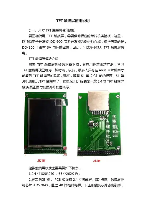
TFT 触摸屏模块介绍随着TFT 触摸屏价格的不断下降,其应用也越来越广泛,学习TFT 触摸屏现已成为一种时尚,以前,很多人只有在ARM 单片机中才能看到TFT 触摸屏的风采,现在,随着51单片机性能的提高,51单片机也能玩TFT 触摸屏了,这里,我们介绍的是一款2.4寸TFT 触摸屏模块,其正面与反面外形如图所示:这款触摸屏模块主要具备如下特点:1.2.4寸320*240 ,65K/262K 色;2.屏带PCB 板, PCB 板设有2.4寸液晶屏、SD 卡座、触摸屏控制芯片ADS7843,通过40脚插针将屏、卡座和触摸芯片功能引脚,引脚间距为2.54mm ,采用杜邦线可十分方便地与单片机进行连接。
PCB 引出脚排列及功能如图所示:3.屏设置为8位,用户也可根据实际情况设置为16位。
4.控制IC 为ILI9325。
二、供电及连接说明DD-900实验开发板采用的是5V 供电,因此,单片机应采用5V 单片机,如STC89C516RD+、STC12C5A60S2等,晶振采用30M ,注意TFT 要采用3V 供电,否则有可能烧屏,TFT 与单片机连接时可加限流电阻,电阻大小为470欧左右,也可以不加,但单片机不可设置为推挽模式,各引脚连接如下: TFT 触摸屏 DD-900实验开发板说明GND GND 屏与背光供电VCC 3V LED+ 3V DB8~DB15 P00~P07 液晶屏部分DB0~DB7不连接(这里采用是8位方式,不用连接)RS P26 WR P25 RD P24 CS P27 RES P23 D_CLK P21 触摸控制部分D_CS P20 D_DIN P22 D_BUSY P34 D_DOUT P33 D_Penirq (中断) P35 SD_OUT 根据程序进行定义 SD 卡座部分(前两个实验,此部分未采用) SD_SCK 根据程序进行定义SD_DIN根据程序进行定义SD_CS 根据程序进行定义注意:在TFT 的PCB 板上标有TFT 的引脚功能,一定要认清管脚与标注的对应关系。
高通智能机下载平台操作指南
一、安装程序
1、手机开机安装程序,选择驱动“C:\QCUSBNetworkCombo\Qualcomm”,先把4个串口驱动安装好。
2、先找到软件安装文件“”,打开里面压缩包“”,解压到当前文件,把里面文件夹内的“”文件夹拷贝到C盘根目录下。
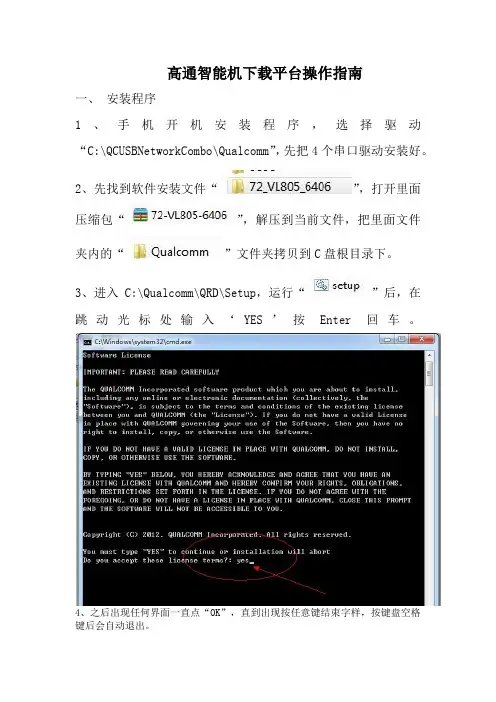
3、进入C:\Qualcomm\QRD\Setup,运行“”后,在跳动光标处输入‘YES’按Enter回车。
4、之后出现任何界面一直点“OK”,直到出现按任意键结束字样,按键盘空格
键后会自动退出。
二、调试
1、QSPR调试:
A、先把软件升级辅助工具“”,放到D盘根目录
下,并在D盘根目录下新建存放软件文件夹,如“”。
B、用户操作权限注册,先运行“”,运行完成后,再注销电脑一次。
C、运行桌面生存图标“”,选择工具引导路径:C:\Qualcomm\QRD\XTT\SWDownload\7627A\QRD_7627A_SoftwareUpgrade_NAND
D、内部调试按图示,(在内文档内看不清,可以选择另存图到桌面放大看)。
E、再调试如下图步骤,完成后点保存,再退出,QPSR调试完成
三、 QMSCT调试
进入开始菜单,选择QMSCT,再点击“”,按图片标注调试(调试串口时要把选上,把串口改好后,再保存,再取消打勾),所以项目调试好保存后再退出,每次更改软件选择软件后,必须存盘后,把QMSCT主程序关掉,再重新打开,手机开机插上数据线后就能自动下载,完成后会显示PASS,完成时间大楖在2:30---3:40.。
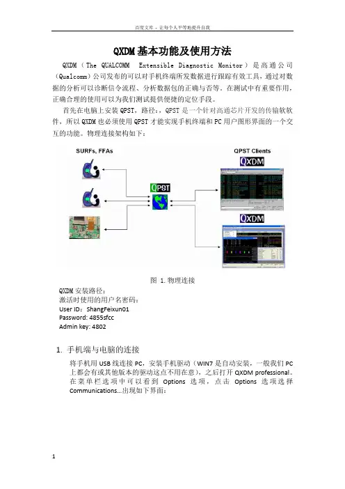
QXDM基本功能及使用方法QXDM(The QUALCOMM Extensible Diagnostic Monitor)是高通公司(Qualcomm)公司发布的可以对手机终端所发数据进行跟踪有效工具,通过对数据的分析可以诊断信令流程、分析数据包的正确与否等。
在测试中有重要作用,正确合理的使用可以为我们测试提供便捷的定位手段。
首先在电脑上安装QPST,路径:,QPST是一个针对高通芯片开发的传输软软件,所以QXDM也必须使用QPST才能实现手机终端和PC用户图形界面的一个交互的功能。
物理连接架构如下:图 1.物理连接QXDM安装路径:激活时使用的用户名密码:User ID:ShangFeixun01Password: 4855sfccAdmin key: 48021.手机端与电脑的连接将手机用USB线连接PC,安装手机驱动(WIN7是自动安装,一般我们PC 上都会有或其他版本的驱动这点不用在意),之后打开QXDM professional。
在菜单栏选项中可以看到Options选项,点击Options选项选择Communications…出现如下界面:图2 Communications从上图可以看到COM28端口的Phone选项中能读出手机端口,这样我们可以直接在①处直接选择COM28,然后点击OK。
但往往有时候在上面的端口表中不一定会显示出含有手机端口的COM口,这是我们就要借助QPST了,双击下图中的小地球图3 QPST port之后出现如图4所示的窗口,查看列表看是否有连接手机端的COM口,若无则点击Add new port图4 QPST Configuration在图5中点击COM口,然后点击ok,完成对COM口的添加图5 Add new port特殊情况:找不到口的情况下,可在电脑设备管理器的端口选项查看端口是否正常,若无端口或者端口有叹号提示,则重新安装手机驱动或这启动电脑。
若端口显示正常却在QPST中无法找到,可在打开手机工厂模式中的USBFunctions,选择All USB Function。
LAM-N760,N760SP_ENG7inch Wide TFT colorTV System/Mobile Monitor OWNER’S MANUALLAM-N760SP/N760Before connecting, operating or adjusting thisproduct, please read this instruction bookletcarefully and completely.Main features7-8 Installation9-14 Parts supplied . . . . . . . . . . . . . . . . . . . . . . . . . . . . . . .9 Before installing . . . . . . . . . . . . . . . . . . . . . . . . . . . . .9 Installation order for the stand . . . . . . . . . . . . . . . . . .10 Treatment of monitor cable . . . . . . . . . . . . . . . . . . . .11 Installation of monitor unit . . . . . . . . . . . . . . . . . . .11-12 Installation order for the stand (Rear seat monitor) . . .13 Connection of exterior units . . . . . . . . . . . . . . . . . . . .14 Parts name15-17 Front view . . . . . . . . . . . . . . . . . . . . . . . . . . . . . . . . .15 Rear view . . . . . . . . . . . . . . . . . . . . . . . . . . . . . . . . .16 Remote control . . . . . . . . . . . . . . . . . . . . . . . . . . . . .17 Battery installation . . . . . . . . . . . . . . . . . . . . . . . . . . .17 Operation18-21 Power ON/OFF . . . . . . . . . . . . . . . . . . . . . . . . . . . . .18 Mode conversion . . . . . . . . . . . . . . . . . . . . . . . . . . . .18 Adjusting the volume . . . . . . . . . . . . . . . . . . . . . . . . .18 Mute . . . . . . . . . . . . . . . . . . . . . . . . . . . . . . . . . . . . .18 To enter the PICTURE menu . . . . . . . . . . . . . . . . . . .19 Adjusting PICTURE menu . . . . . . . . . . . . . . . . . . . . .19 To enter the TUNING menu . . . . . . . . . . . . . . . . . . . .19 Adjusting TUNING menu . . . . . . . . . . . . . . . . . . . . . .19 AUTO MEMORY . . . . . . . . . . . . . . . . . . . . . . . . . . . .20 SOUND SYSTEM . . . . . . . . . . . . . . . . . . . . . . . . . . .20 ADD/ERASE . . . . . . . . . . . . . . . . . . . . . . . . . . . . . . .20 FINE TUNE . . . . . . . . . . . . . . . . . . . . . . . . . . . . . . . .21 ALL RESET . . . . . . . . . . . . . . . . . . . . . . . . . . . . . . . .21 Troubleshooting22-23 Specifications242The lightning flash with arrowhead symbol, within an equilateral triangle is intended to alert the user about the presence of uninsulated dangerous voltage within the product’s enclosure that may be of sufficient magnitude to constitute a risk of electric shock. The exclamation point within an equilateral triangle is intended toalert the user to the presence of important operating and maintenance (servicing) instructions in the literature accompanying the appliance.To prevent a user or others from any physical or financial damage, please abide by the following. The following indications describe thedegree of danger or damage for the misusage.Warning“Warns the possibility of heavy injury or death.”Notice“likely to be injured or damaged physically.”Prohibition“Must not”Compulsion“Do it necessarily.”3NoteTV functions only for LAM-N760SPNoteTV functions only for LAM-N760SP5Disposal of your old appliance1. When this crossed-out wheeled bin symbol is attached to a product,it means the product is covered by the European Directive 2002/96/EC. 2. All electrical and electronic products should be disposed of separately fromthe municipal waste stream via designated collection facilities appointed by the government or the local authorities.3. The correct disposal of your old appliance will help prevent potentialnegative consequences for the environment and human health.4. For more detailed information about disposal of your old appliance, pleasecontact your city office, waste disposal service or the shop where you purchased the product.This product has been manufactured to comply with the radio interferencerequirements of EEC DIRECTIVE 89/336/EEC, 93/68/EEC and 73/23/EEC.7NoteTV functions only for LAM-N760SP.89At low temperature (20°C… or less) Turn on the heater for a proper temperature.(to enhance adhesive power).At high humidity (fog, rain and so on)After making adhesive side dried with a dryer,install the unit.After installing of the StandPulling the Monitor stand or installing the Monitor within 24 hours of the stand installation mayweaken adhesive power of the stand.Before installingAV Cable Earphone Cigar light adapter Remote Control Section-mount cradle (Rear)Section-mount cradle(Front)101112NoteRefer to your car’s user guide.A14NoteTV functions only for LAM-N760SP .When the AV Cable is insert and pulled out of the AV jack, the picture will flicker for a short moment, which is normal.15161.Left/ Right Speakers Antenna (This functions only for LAM-N760SP .)3.Docking connectorNoteActual player may vary slightly from images shown.171.Remove the battery holder with a pencil orball point pen.2.Install the battery on the battery holder.3.Install the battery holder back into its originalposition.Notes•Use only one CR2025 (3V) lithium battery.•Remove the battery if the remote control is not used for a long period of time.•Do not leave the product in a hot or humid place.•Do not handle the battery with metallic tools.•Do not store the battery with metallic materials.•In the event of battery leakage, wipe the remote control completely clean and install a new battery.Battery installationNoteWhen power of the main system is turned on or off, the picture sometimes flicker, which is normal.Notes•If power is supplied to the main system, the TV memorizes the previous status and makesNoteWhen you turn the unit off, the current volume level is automatically memorized.2. PressNoteWhen you press the AV1/AV2 switch, the pic-ture will flicker for seconds, which is normal.NoteWhen the DISPLYand 4:3, the picture will flicker for a second, ArrayTV functions only for LAM-N760SP.19202122service center in this manual and we will take a proper action. (As this product is assembled in delicate parts, only a skilled technician is recommended for the disassembly of product.)Small red, blue and green points display on the screen.•LCD screen is made in a high technology. So, this may happen due to lack of pixels by 0.001% or frequent lighting up of pixels. But, it is not the reason of any trouble.Audio and Video do not work.•Check if the starting switch of a car is on ACC or ON.•Check whether a connection code is unstable or is disconnected. •This does not work while driving.Video works but Audio does not.•Check with a volume controller if the volume level is proper.•Check whether an output port for voice is connected.The corner of the screen displays on TV.•If LCD screen has been used for long dark hours, it becomes dark gradually.•If it gets dark severely, replace its exclusive fluorescent tube.Voice quality is bad while receiving TV signal.•Change the frequency in case of interference from a radio displays only in black.•Check its color by adjusting Color Set on Menu.Note TV functions only for LAM-N760SP .bad.It noises.It noises.It noises.23P/NO : MFL3175340524。
手机处理器芯片详解(一)文字整理:董海礁 (MCA) 制表:王毅(T echFaith)新浪微博:@Joyce_董海礁 @TF_王毅纰漏之处,欢迎指正 智能手机自面世以来,就迅速掠夺功能手机市场,占据了手机市场的半壁江山。
随着3G网络的爆发,越来越多的消费者开始关注手机的性能,同时手机芯片厂商也开始逐渐走进大众视野。
然而面对国内外众多的芯片厂商以及琳琅满目的处理器型号,再加上一些拗口的复杂命名会让许多大众用户看花了眼,本文将针对这个问题,为大家详细介绍目前国内外主要的手机处理器芯片厂商以及产品命名规则、特性等。
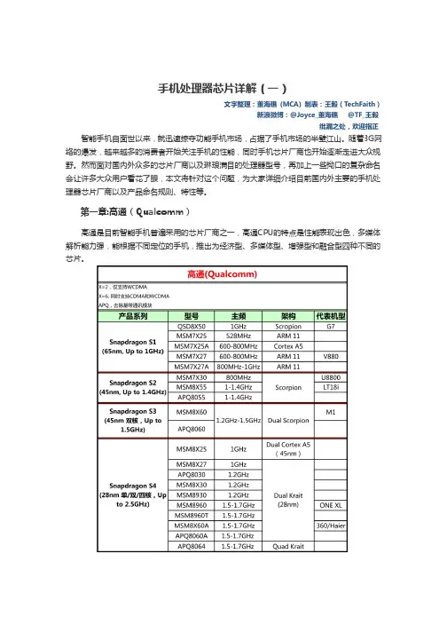
第一章:高通(Qualcomm)高通是目前智能手机普遍采用的芯片厂商之一,高通CPU的特点是性能表现出色,多媒体解析能力强,能根据不同定位的手机,推出为经济型、多媒体型、增强型和融合型四种不同的芯片。
目前,高通已将旗下的手机处理器统一规划为Snapdragon(骁龙)品牌,根据处理器性能和功能定位的不同,又将其由低到高分为S1、S2、S3、S4四个类别。
其中S1针对大众市场的智能手机产品,也就是我们所熟知的千元内智能手机;S2针对高性能的智能手机和平板电脑;S3在S2的基础上对多任务以及游戏方面有更大提升;S4是高通目前最高端,同时性能也最强的处理器系列,其中的双核以及四核产品主要针对下一代的终端产品,包括Windows8平板等。
高通Snapdragon S1:65nm制程 面向低端智能终端高通Snapdragon S1处理器主要是针对大众市场的智能手机,所包括的处理器型号含Snapdragon QSD8x50、MSM7x25、MSM7x27、MSM7x25A和 MSM7x27A系列。
Snapdragon S1采用65nm制程,最高配置1GHz主频和Adreno 200图形处理器。
在这里要说明的是,X为2时代表只支持WCDMA制式,X为6时代表同时支持CDMA和WCDMA制式,这一规则同样适用于高通Snapdragon 其它系列。
高通工具使用指导书文档密级内部学习高通工具使用指导书(QXDM、QPST、QCAT)作者:白志伟日期:2015.5.29华锐通讯科技有限公司高通工具使用指导书文档密级内部学习目录1.版本路径 (3)1.1 QXDM 路径 (3)1.2 QPST路径 (3)1.3 QACT 路径 (3)2. QPST 的使用 (3)2.1 QPST简介 (3)2.2 QPST 安装 (3)2.3 QPST使用 (6)2.3.1 QPST configuration (6)2.3.2 EFS Explorer (7)2.3.3 software download (9)2.3.3 QCNview (20)2.3.4 memory debug application (21)2.3.5 service programming (22)2.3.6 PRL editor (27)3. QXDM的使用 (28)3.1 QXDM简介 (28)3.2 QXDM 安装 (28)3.3 在线激活QXDM (29)3.4 QXDM使用 (30)3.4.1 com口连接 (30)3.4.2 log窗口(快捷键F1) (32)3.4.3 message窗口(快捷键F3) (32)3.4.4 item 窗口(快捷键F11) (33)3.4.5 设置log view configuration (33)3.4.6 设置message view configuration (38)3.4.7 log过滤 (43)3.4.8 mach item 查找log (45)3.4.9 log保存 (45)3.4.10 log自动保存 (46)3.4.11 command 命令输入框 (46)3.4.12 nv browser (47)3.4.13 status 查看设备网络状态 (47)3.4.14 item replay (48)3.4.15 清空log (48)3.4.16 查看WCDMA网络搜网状态 (49)3.4.17 查询WCDMA当前收发功率 (49)3.4.18 查看终端注册到WCDMA网络状态 (50)3.4.19 查看功控信息 (50)华锐通讯科技有限公司高通工具使用指导书文档密级内部学习3.4.20 ppp extractor功能 (51)3.4.21 evdo搜网状态 (52)3.4.22 查看evdo注册网络信息 (52)4.3.23 EVDO连接态注册信息查看 (52)4.3.24查看lte 信号强度 (53)4.3.25查看小区重选 (53)4. QCAT 简介 (54)1.版本路径1.1 QXDM 路径\\192.168.99.240\software\Qualcomm\Software Tools\QXDM Software Code1.2 QPST路径\\192.168.99.240\software\Qualcomm\Software Tools\QPST Software Code1.3 QACT 路径\\192.168.99.240\software\Qualcomm\Software Tools\QACT Software Code每个工具都需要获取最新的版本进行安装2. QPST 的使用2.1 QPST简介QPST是高通公司开发的一套软件,该工具可以对设备的内部参数进行读写和操作,用于使用高通平台的设备的EFS管理、图像捕捉、软件下载等。
w w w.d a t a v i d e o.c o m7" TFT LCD MONITOR2Standard Warranty• Datavideo equipment is guaranteed against any manufacturing defects for one year from the date of purchase.• The original purchase invoice or other documentary evidence should be supplied at the time of any request for repair under warranty.• Damage caused by accident, misuse, unauthorized repairs, sand, grit or water is not covered by this warranty.• All mail or transportation costs including insurance are at the expense of the owner.• All other claims of any nature are not covered.• Cables & batteries are not covered under warranty.• Warranty only valid within the country or region of purchase.• Your statutory rights are not affected.Two Year Warranty• All Datavideo products purchased after 01-Oct.-2008 qualify for a free one year extension to the standard Warranty, providing the product is registered with Datavideo within 30 days of purchase. For information on how to register please visit or contact your local Datavideo office or authorized Distributors• Certain parts with limited lifetime expectancy such as LCD Panels, DVD Drives, Hard Drives are only covered for the first 10,000 hours, or 1 year (whichever comes first).• Any second year warranty claims must be made to your local Datavideo office or one of its authorized Distributors before the extended warranty expires.WarrantyWelcome to the TLM-700HD Instruction ManualThank you for choosing a Datavideo product, pleasevisit the support pages on our website for the latestversion of the instruction manual./LCD+Monitors/TLM-700HDDon’t forget to register your product online to qualify foran additional free one year extension to the standardwarranty, and to receive information from Datavideo onservice & information relevant to your Datavideo productincluding new software updates & driversTLM-700HD3Disclaimer of Product and Services The information offered in this instruction manual is intended as a guide only. At all times, Datavideo Technologies will try to give correct, complete and suitable information. However, Datavideo Technologies cannot exclude that some information in this manual, from time to time, may not be correct or may be incomplete. This manual may contain typing errors, omissions or incorrect information. Datavideo Technologies always recommend that you double check the information in this document for accuracy before making any purchase decision or using the product. Datavideo Technologies is not responsible for any omissions or errors, or for any subsequent loss or damage caused by using the information contained within this manual. Further advice on the content of this manual or on the product can be obtained by contacting your local Datavideo Office or dealer. ContentsWelcome to the TLM-700HD Instruction Manual 2Warranty 2Standard Warranty 2Two Year Warranty 2Disposal 4Warnings and Precautions 4Packing List 5Introduction 5Features 6Supported Formats 6Connections & Controls 7Front Panel 7Rear Panel 9Menu Options 101. Picture (Screen Setup) 10Picture setting 10Brightness 102. Audio (Audio Indicator) 103. Function (Center Mark, Safety Zone) 10Center Mark 10Safety Zone 104. Setup (On Screen Display, Time Code) 11OSD Timer 11OSD Blending 11Time Code 11TC Position 11TC HD Line 11TC SD Line 11TC Font Size 115. Advance (LCD Display, Reset Firmware Version) 12LCD L/R Scan 12LCD U/D Scan 12Reset 12Calibrating Datavideo Monitors 12Tally light indication 13TLM-700HD Model & Battery Plate Variations 14Specifications 15Service & Support 167" TFT LCD MONITOR4Warnings and Precautions1.Read all of these warnings and save them for later reference.2.Follow all warnings and instructions marked on this unit.3.Unplug this unit from the wall outlet before cleaning. Do not use liquid or aerosol cleaners. Use a slightly damp cloth for cleaning.4.Do not use this unit in or near water.5.Do not place this unit on an unstable surface, cart, stand, or table. The unit may fall, causing serious damage.6.Any slots and openings on the case top, back, and bottom are provided for ventilation. To ensure safe and reliable operation of this unit, and to protect it from overheating, do not block or cover these openings. Do not place this unit on a bed, sofa, rug, or similar surface, as the ventilation openings may become blocked. This unit should never be placed near or over a heat source or radiator. This unit should not be placed in a built-in installation unless proper ventilation is provided.7.This product should only be operated from the type of power source indicated on the marking label of the AC adapter. If you are not sure of the type of power available, consult your Datavideo dealer or your local power company.8.Do not allow anything to rest on the power cord. Do not locate this unit where the power cord will be walked on, rolled over, damaged or otherwise stressed.9.If an extension cord must be used with this unit, make sure that the total of the ampere ratings on the products plugged into the extension cord do not exceed the extension cord’s rating.10.Make sure that the total amperes of all the units that are plugged into asingle wall outlet do not exceed 15 amperes.11.Never push objects of any kind into this unit through the case ventilationslots, as they may touch dangerous voltage points or short out parts that could result in risk of fire or electric shock. Never spill liquid of any kind onto or into this unit.12.Except as specifically explained elsewhere in this manual, do not attemptFor EU Customers only - WEEE MarkingThis symbol on the product indicates that it will not be treatedas household waste. It must be handed over to the applicabletake back scheme for the recycling of electrical and electronicequipment. For more detailed information about the recycling ofthis product, please contact your local Datavideo office.DisposalTLM-700HD5Introductionto service this product yourself. Opening or removing covers that are marked “Do Not Remove” may expose you to dangerous voltage points or other risks, and will void your warranty. Refer all service issues to qualified service personnel.13.Unplug this product from the wall outlet and refer to qualified service personnel under the following conditions:a.When the power cord is damaged or frayed;b.When liquid has spilled into the unit;c.When the product has been exposed to rain or water;d.When the product does not operate normally under normal operating conditions. Adjust only those controls that are covered by the operating instructions in this manual; improper adjustment of other controls may result in damage to the unit and may often require extensive work by a qualified technician to restore the unit to normal operation;e.When the product has been dropped or the case has been damaged;f. When the product exhibits a distinct change in performance, indicating a need for service.The Datavideo TLM-700HD is a 7 Inch monitor designed for use in the field or in a studio. The TLM-700HD can be powered from a standard V-Mount battery connection or by mains power. It is rugged and easy to carry with a variety of professional features and connections that make it easy for set up and intuitive to use.7" TFT LCD MONITOR6FeaturesSupported Formats• 7" 16:9 Wide Screen Panel• Resolution: 800 x 480 dots• View Angle (V)+60/-40°, (H)+60/-60°• HD/SD-SDI, YUV, HD-YUV, HDMI & CV Input• Internal colour bar• Blue only function• Audio indicator for SDI, HDMI• Safe Area indicator• VITC time code display• Dual colour tally light indicator• Brightness, Contrast, Colour, Tint Adjustable• Colour T emp* adjustable• Audio Level indicators• NTSC / PAL Auto Switching• 4:3 / 15:9 / 16:9 switchable* can be set to 9300, 7500, 6500, 5400 or USER RGB values.■ HDMI YUV• 720 x 576i x 50 Hz• 720 x 480i x 60 Hz• 1280 x 720p x 50 Hz• 1280 x 720p x 60 Hz• 1920 x 1080i x 50 Hz• 1920 x 1080i x 60 Hz■ HDMI RGB• 720 x 576i x 50 Hz• 720 x 480i x 60 Hz• 1280 x 720p x 50 Hz• 1280 x 720p x 60 Hz• 1920 x 1080i x 50 Hz• 1920 x 1080i x 60 Hz■ SDI• 720 x 576i / 50 Hz• 720 x 480i / 60 Hz• 1280 x 720p / 60 Hz• 1280 x 720p / 50 Hz• 1920 x 1080i / 50 Hz• 1920 x 1080i / 60 Hz■ YUV• 720 x 576i x 50 Hz• 720 x 480i x 60 Hz• 1280 x 720p x 50 Hz• 1280 x 720p x 60 Hz• 1920 x 1080i x 50 Hz• 1920 x 1080i x 60 Hz■ CV• 720 x 576i (PAL)• 720 x 480i (NTSC)TLM-700HD7Front Panel Connections & ControlsPOWERON OFFSOURCEASPECT Power Switch Switches the power On / Off.Stereo Headphone Mini Jack socket The level is adjusted by headphone volume control.Listen to embedded audio from HDMI or SDI sources.Source Button Selects Input include SDI, YPbPr, CVBS, and HDMI.Aspect Ratio Button Select 4.3, 15:9, or 16:9PATTERN Generate on colour bars.7" TFT LCD MONITOR8BLUEFor blue only display to allow accurate chromaand phase adjustments with NTSC signals.MENUCalls up the on-screen adjustment menu (SeePage10 Menu Options for more details).UP / DOWNMenu navigation controls.ENTERConfirms the new settings or return to the defaultstate.TALLY LIGHTRed = LiveAmber = StandbyMENUENTERTLM-700HD9BNC connector for Analogue (Composite) videoinput.HDMI in interface Supports HDMI 1.1Tally In Sends in red and amber colour tally signal to tally LED. Red means on-air, amber means standby.DC in socket Connects the supplied 12V 1A PSU to this socket. The connection can be secured by screwing the outer fastening ring of the DC In plug to the socket.7" TFT LCD MONITOR10Menu Options1. Picture (Screen Setup)Picture setting■ Press the MENU button once to display the Picture setting menu.■ Press the ENTER button to highlight the Brightness setting.■ Press the UP or DOWN button to highlight the setting that needs to be adjusted.Brightness■ Press ENTER button to select the Brightness setting.■ Press the UP or DOWN button to adjust the Brightness value between 0 and 100.■ Press ENTER button again to save and return to the Picture setting menu;now highlight another Picture setting to be adjusted. To select a different setting (Contrast, Saturation, Tint, Color Temp*) use the UP / DOWN buttons. Follow the same procedure to set the other values.■ Keep pressing the MENU button to cycle through the main menu options.■ Press the SOURCE button to exit the menu mode.* N.B.: Color Temp can be set to 9300, 7500, 6500, 5400 or USER RGB values.2. Audio (Audio Indicator)■ Press the MENU button twice to display the Audio setting menu.■ Press the ENTER button to highlight the Indicator setting.■ Press the ENTER button again to toggle the on screen audio indicator ON/OFF.■ Keep pressing the MENU button to cycle through the main menu options.■ Press the SOURCE button to exit the menu mode.3. Function (Center Mark, Safety Zone)■ Press the MENU button three times to display the Function. Settings menu.Center Mark■ Press the ENTER button to highlight the Center Mark setting.■ Press the ENTER button to toggle the on screen Center Mark ON/OFF. Safety Zone■ Press the UP or DOWN button to highlight the Safety Zone setting.■ Keep pressing the ENTER button to cycle through the values 80%, 90% or OFF.■ Press the UP or DOWN button to exit the Safety Zone setting. To selecta different setting (4:3 Screen, Cinema Zone) use the UP or DOWNbuttons. Follow the same procedure to set the next setting.■ Keep pressing the MENU button to cycle through the main menu options.■ Press the SOURCE button to exit the menu mode.TLM-700HD114. Setup (On Screen Display, Time Code)■ Press the MENU button four times to display the Setup setting menu.OSD Timer■ Press the ENTER button to highlight the OSD Timer setting.* N.B.: OSD Timer sets how long the setting menus will stay on screen.■ Press the ENTER button again to display the OSD Timer setting position.■ Press the UP or DOWN button to set the OSD value between 5 to 60 SEC.■ Press ENTER button to save the OSD value.OSD Blending■ Press the UP or DOWN button to highlight the OSD Blending setting.* N.B.: OSD Blending sets how transparent the setting menus will be on screen.■ Press the ENTER button to display the OSD Blending setting position.■ Press the UP or DOWN button to select the OSD blending value (from 0~7).* N.B.: OSD Blending value 0 = Min transparency 7 = Max transparency ■ Press the ENTER button to save the OSD blending value. Time Code■ Press the UP or DOWN button to highlight the Time Code setting.■ Press the ENTER button to toggle the on screen Time Code display ON/OFF.TC Position■ Press the UP or DOWN button to highlight the TC Position setting.* N.B.: TC Position is used to set where on the monitor Time Code will be shown.■ Press the ENTER button to cycle through the possible Time Code Positions on the monitor (Left/Up, Middle/Down, Right/Down, Right/Up)TC HD Line■ Press the UP or DOWN button to highlight the TC HD Line setting.■ Press ENTER button to cycle through the possible HD time code lines (8~20).TC SD Line■ Press the UP or DOWN button to highlight the TC SD Line setting.■ Press ENTER button to cycle through the possible SD time code lines (10~21).TC Font Size■ Press the UP or DOWN button to highlight the TC Font Size setting.■ Press ENTER button to cycle through the possible time code font sizes on the screen (Large or Small).■ Keep pressing the MENU button to cycle through the main menu options.■ Press the SOURCE button to exit the menu mode.7" TFT LCD MONITOR12Calibrating Datavideo MonitorsCalibrating professional monitors is crucial.For guidance on how to calibrate a Datavideo Monitor using SMPTE colour bars please visit our website /specs/Datavideo_Calibrating_Monitors.pdf 5. Advance (LCD Display, Reset Firmware Version)■ Press the MENU button five times to display the Advance setting menu.LCD L/R Scan■ Press the ENTER button to highlight the LCD L/R Scan setting.* N.B.: The LCD L/R Scan will reverse the image displayed horizontally.■ Press the ENTER button, the screen image will be reversed (Left to Right).■ Press the ENTER button again, the screen image will return to normal view.LCD U/D Scan■ Press UP / DOWN button to highlight the LCD U/D Scan setting.* N.B.: The LCD U/D Scan will reverse the image displayed vertically.■ Press the ENTER button, the screen image will be reversed (Top to Bottom).■ Press the ENTER button again, the screen image will return to normal view.Reset■ Press UP / DOWN button to highlight the Reset option.* N.B.: This option will return the monitor to the factory default settings.■ Press the ENTER button to re-start the monitor with the factory default settings.Version■ Press UP / DOWN button to highlight the Version setting.■ Press the ENTER button, the firmware version will be displayed on screen.■ Keep pressing the MENU button to cycle through the main menu options.■ Press the SOURCE button to exit the menu mode.TLM-700HD13Tally light indicationThe TLM-700HD has a tally input connector on the rear panel; many digital video switchers can provide tally light signals to this connector. The Datavideo range of intercom systems can also be used to pass on thesetally signals.Tally InD-sub 15pin type connector.TALLY LIGHTRed = LiveAmber = Standby7" TFT LCD MONITOR14TLM-700HD Model & Battery Plate VariationsTLM-700HD:with V-mount Battery PlateTLM-700HD-C:with Canon battery mountTLM-700HD-P:with Panasonic battery mountTLM-700HD-S1 & -S2:with Sony battery mountTLM-700HD-A:with Anton Bauer battery mountThere are several versions ofTLM-700HD monitor with differentbattery connection plates.TLM-700HD Specifications15All the trademarks are the properties of their respective owners. Datavideo Technologies Co., Ltd. All rights reserved 2018Service & SupportJan-24.2014 P/N: G082060476E6It is our goal to make your products ownership a satisfying experience. Our supporting staff is available to assist you in setting up and operating your system. Please refer to our web site for answers to common questions, support requests or contact your local office below.R.O.C.U.S.A.Datavideo Technologies (S) PTE Ltd No. 178 Paya Lebar Road #06-03Singapore 409030Tel:+65-6749 6866Fax:+65-6749 3266E-mail:******************Datavideo United KingdomDatavideo SingaporeDatavideo UK LimitedUnits1 & 2 Waterside Business Park Hadfield, Glossop, Derbyshire SK13 1BE, UKTel:+44-1457 851 000Fax:+44-1457 850 964E-mail:******************.ukDatavideo IndiaDatavideo Technologies India Pvt Ltd Fax:+91-0120-2427338E-mail:******************Tel:+91-0120-2427337A-132, Sec-63,Noida-201307,Uttar Pradesh (UP), India.Datavideo Technologies Co. Ltd10F. No. 176, Jian 1st Rd.,Chung Ho District, New Taipei City 235, Taiwan, Tel: +886-2-8227-2888Fax: +886-2-8227-2777E-mail:*********************.twDatavideo Corporation 7048 Elmer Avenue.Whittier, CA 90602, Tel:+1-562-696 2324Fax:+1-562-698 6930E-mail:******************Datavideo USADatavideo TaiwanDatavideo Hong KongDatavideo Hong Kong Ltd G/F.,26 Cross Lane Wanchai, Hong Kong Tel: +852-2833-1981Fax: +852-2833-9916E-mail:******************.hkDatavideo Technologies Europe BV Floridadreef 1063565 AM Utrecht, The NetherlandsTel:+31-30-261-96-56Fax:+31-30-261-96-57E-mail:*****************Datavideo The NetherlandDatavideo ChinaDatavideo Technologies China Co101,NO.618,LiuYing Rd,Zhabei District,Shanghai,ChinaTel: +86 21-5603 6599Fax: +86 21-5603 6770E-mail:********************Datavideo FranceDatavideo France s.a.r.lCité Descartes 1,rue Albert Einstein Champs sur Marne774477-Marne la Vallée cedex 2Tel:+33-1-60370246E-mail:*****************。
Copyright 2012 © Embedded Artists AB3.2 inch QVGA TFT Color LCDUser’s GuideVersion 1 & 2Give graphics and color to your application!Embedded Artists ABDavidshallsgatan 16SE-211 45 MalmöSweden************************Copyright 2005-2012 © Embedded Artists AB. All rights reserved.No part of this publication may be reproduced, transmitted, transcribed, stored in a retrieval system, or translated into any language or computer language, in any form or by any means, electronic, mechanical, magnetic, optical, chemical, manual or otherwise, without the prior written permission of Embedded Artists AB.DisclaimerEmbedded Artists AB makes no representation or warranties with respect to the contents hereof and specifically disclaim any implied warranties or merchantability or fitness for any particular purpose. Information in this publication is subject to change without notice and does not represent a commitment on the part of Embedded Artists AB.FeedbackWe appreciate any feedback you may have for improvements on this document. Please send your comments to ***************************.TrademarksAll brand and product names mentioned herein are trademarks, services marks, registered trademarks, or registered service marks of their respective owners and should be treated as such.Table of Contents1Document Revision History4 2Introduction5 2.1Features5 2.2Version 1 vs. Version 25 2.3ESD Precaution6 2.4General Handling Care6 2.5CE Assessment6 2.6Other Products from Embedded Artists6 2.6.1Design and Production Services6 2.6.2OEM / Education / QuickStart Boards and Kits7 3Design Description8 3.1Backlight Control8 3.2On-board LCD Controller, display version 28 3.3On-board touch screen Controller, display version 29 3.4On-board LCD Controller, display version 19 3.5Interface (pin description)10 3.6Optimum Viewing Angle13 3.7Connecting version 2 to OEM Base Board < v1.514 4Board Mechanical Dimensions161 Document Revision History2 IntroductionThank you for buying Embedded Artists’ 3.2 inch QVGA TFT Color LCD Board based on a LCD from Truly. Sample applications for our NXP LPC2xxx based boards are also provided and can be downloaded from the support page. The 3.2 inch QVGA TFT Color LCD Board will be called the QVGA LCD Board for short in the rest of this document.2.1 FeaturesThe QVGA LCD Board has the following features:∙Optional touch screen interface (available for version 2)∙8-bit or 16-bit parallel interface. Only occupies 2 addresses (i.e., one address pin) or serial 8-bit (SPI-like) interface (max 10 MHz clock)∙Diagonal size: 3.2 inch∙Display technology: TFT∙Display mode: Transmissive∙No of pixels: 240xRGBx320 (QVGA size)∙Supply voltage: 3.0-3.3V∙White LED backlight, with PWM control∙View area: 48.6 x 64.8 mm∙Dot size: 0.2025 x 0.2025 mm∙Operating temperature: -20 to + 70 degrees Celsius∙No of colors: 262K (if 18-bit mode), 65k (if 16-bit mode)∙2x20 pos connector (100 mil spacing) is required to interface the module, plus optional 1x6 pos connector∙Small form factor: 93 x 83 mm2.2 Version 1 vs. Version 2There exist two versions of the display. Version 1 uses a display from one display manufacturer and version 2 uses a display from another manufacturer.The similarities between the versions are:∙Same physical size of display module.∙Same optical features and capabilities.∙Same main 2x20 pos interface connector (100 mil spacing).The differences are:∙Different internal display controllers are used. The programming interface is not identical but very similar. A reference software driver exists that supports both versions simultaneous.∙Version 2 of the display module has a touch screen option.∙ A 6 pos extra interface connector has been added beside the main 2x20 pos interface connector. This extra connector carries signals for touch screen interface and some extrasignals for direct RGB-control of display (useful when interfacing the LPC2478 MCU from2.3 ESD PrecautionPlease note that the QVGA LCD Board comes without any case/box and allcomponents are exposed for finger touches – and therefore extra attention mustbe paid to ESD (electrostatic discharge) precaution.Make it a habit always to first touch a ground pin/hole for a few secondswith both hands before touching any other parts of the boards. That way,you will have the same potential as the board and therefore minimize the risk forESD.Note that Embedded Artists does not replace boards that have been damaged by ESD.2.4 General Handling CareHandle the QVGA LCD Board with care. The boards are not mounted in a protective case/box and are not designed for rough physical handling. Connectors can ware out after excessive use. The QVGA LCD Board is designed for prototyping use, and not for integration into an end-product.Do not exercise excessive pressure on the LCD glass area. That will damage the display. Also, do not apply pressure on the flex cables connecting the LCD/touch screen. These are relatively sensitive and can be damaged if too much pressure is applied to them.Note that Embedded Artists does not replace boards where the LCD has been improperly handled.2.5 CE AssessmentThe QVGA LCD Board is CE marked. See separate CE Declaration of Conformity document.The QVGA LCD Board is a class A product. In a domestic environment this product may cause radio interference in which case the user may be required to take adequate measures.EMC emission test has been performed on the QVGA LCD Board when connected to Embedded Artists base boards. Connecting the board to other devices may alter EM C emission. It is the user’s responsibility to make sure EMC emission limits are not exceeded when connecting the board to other devices.Due to the nature of the QVGA LCD Board – an evaluation board not for integration into an end-product – fast transient immunity tests and conducted radio-frequency immunity tests have not been executed. Externally connected cables are assumed to be less than 3 meters. The general expansion connectors where internal signals are made available do not have any other ESD protection than from the chip themselves. Observe ESD precaution.Note that the QVGA LCD Board can also be considered to be a component if integrated into another product. The CE mark on the QVGA LCD Board cannot be extended to include the new (user created) product. It is the user’s responsibility to make sure EMC emission limits are not exceeded and CE mark the final product.2.6 Other Products from Embedded ArtistsEmbedded Artists have a broad range of LPC1000/2000/3000/4000 based boards that are very low cost and developed for prototyping / development as well as for OEM applications. Modifications for OEM applications can be done easily, even for modest production volumes. Contact Embedded Artists for further information about design and production services.2.6.1 Design and Production ServicesEmbedded Artists provide design services for custom designs, either completely new or modification to existing boards. Specific peripherals and I/O can be added easily to different designs, for example,broad, and long, experience in designing industrial electronics in general and with NXP’sLPC1000/2000/3000/4000 microcontroller families in specific. Our competence also includes wireless and wired communication for embedded systems. For example IEEE802.11b/g (WLAN), Bluetooth™, ZigBee™, ISM RF, Ethernet, CAN, RS485, and Fieldbuses.2.6.2 OEM / Education / QuickStart Boards and KitsVisit Embedded Artists’ home page, , for information about other OEM / Education / QuickStart boards / kits or contact your local distributor.3 Design DescriptionThis chapter describes the hardware design of the QVGA LCD Board.3.1 Backlight ControlWhite LEDs are used as backlight on the display. The LED current is set to 15 mA. A step-up DC/DC converted is used to generate a constant LED current. The switching frequency is fixed to 1.2 MHz. The intensity of the backlight (i.e., the white LEDs) is varied by varying the LED current. There are two ways to very the LED current between 0-15 mA. A digital PWM signal is needed with the same logic levels as the power supply (typically 3.3V).∙Modulate the shutdown pin of the DC/DC converter (signal LED_SHDN). A low input signal turn off the DC/DC converted and a high level activate it. A high duty cycle on the PWM signal equals high intensity.∙Modulate the current set pin of the DC/DC converter (signal LED_PWM). A low input signal increase the LED current and a high level reduce it. A high duty cycle on the PWM signalequals low intensity.The frequency of the modulation (PWM) signal should ideally be in the 5-10 kHz region.3.2 On-board LCD Controller, display version 2The display has an embedded controller, SSD1289 from Solomon Systech. This controller chip has 1.3 Mbit embedded display RAM, which is enough for storing a complete 320xRGBx240 picture with 18 bit color depth.There are a couple of interface alternatives to this controller. Either 18-bit, 16-bit, 9-bit or 8-bit parallel interface or a serial interface. There are 4 pins that are used to configure the interface. The table below lists the different options. L is statically tied to low logic level and H is statically tied to high logic level.If the parallel interface is selected, there are two different interface types; either 6800 or 8080 style. See datasheet for details about timing and how the different control signals are used.If a serial interface is used, see the datasheet for details about timing and how the different control signals are used. Note that maximum clock frequency is 13 MHz.3.3 On-board touch screen Controller, display version 2The touch screen controller used is TSC2046 from Texas Instruments. This chip has a SPI interface and shares the SI, SO, SCK pins in the main interface connector, with the LCD controller. Pin 45 must however be low (TSC2046 chip CS#) in order to communicate with the touch screen controller. See TSC2046 datasheet for details about the serial interface.3.4 On-board LCD Controller, display version 1The display has an embedded controller, IS2102B from ISRON. This controller chip has 1.3 Mbit embedded display RAM, which is enough for storing a complete 320xRGBx240 picture with 18 bit color depth.There are a couple of interface alternatives to this controller. Either 16-bit or 8-bit parallel interface or a serial interface. There are 6 pins that are used to configure the interface. The table below lists the different options. L is statically tied to low logic level and H is statically tied to high logic level.If the parallel interface is selected, there are two different interface types. The configuration pin C86 is used to select between the i86 interface and the M68 interface. See datasheet for details about timing and how the different control signals are used.If a serial interface is used, see the datasheet for details about timing and how the different control signals are used. Note that maximum clock frequency is 10 MHz.3.5 Interface (pin description)The table below describes the 40 pin interface to the QVGA LCD Module. A 2x20 pos (100 mil spacing) header connector facing down is used. See datasheet for details about interface timing.On display version 2 a new extra 1x6 pos (100 mil spacing) header connector facing down exists. See datasheet for details about interface timing.The picture below illustrates the pin numbering of the QVGA LCD Module .Figure 1 - 3.2 inch QVGA TFT Color LCD Board Pin NumberingPin2Pin403.6 Optimum Viewing AngleOptimum viewing angles are as illustrated below.Figure 2 - 3.2 inch QVGA TFT Color LCD Board Optimum Viewing Angle3.7Connecting version 2 to OEM Base Board < v1.5Version 1.5 and above of the OEM Base Board has direct connectors for all 46 positions in theinterface connector. Version 1.4 and below do not have the 6 extra positions (pos 41-46). These have been added for version2 of the display.The touch screen controller can still be accessed with just one extra wire, from pin 45 on the display module to P0.16 on the OEM Base Board. P0.16 is used for chip select of the touch screen controller. Other pins work just as well, but P0.16 is used on v1.5 and above of the OEM Base Board.Figure 3 - 3.2 inch QVGA TFT Color LCD Board Pin 45Simply connect a wire from pin 45 on the display module to P0.16 on the OEM Base Board. Figure 4 and 5 below illustrate the wire connection. Also note that the three SPI jumpers must be inserted, see Figure 4 for details.Figure 4 – Picture of Wire to Pin 45 on Display Module Figure 5 – Wire to p0.16 on OEM Base Board Three SPI jumpers must be inserted since communication with touch screen controller is via SPI.4 Board Mechanical DimensionsFigure 6 below contains a drawing of the board that includes mechanical measures. Four 4.3 mm grounded mounting holes are used.Figure 6 - 3.2 inch QVGA TFT Color LCD Board Mechanical Dimensions70 mm 93 mm80.0 mm 6.5 mm。
金立s10解锁工具使用说明书(高通平台)V1.1.0金立解锁工具使用说明书(高通平台)版本:V1.1.0制作人:谢昌锋日期:2017-07-15批准人:曾顺兵日期:2017-07-15目录1 工具简介 (4)1.1界面介绍 (4)2 使用方法 (5)3权限说明 (12)4常见问题 (13)5附录 (13)版本历史目标读者工具开发工程师、测试工程师、维修技术员及业务相关人员名词缩写GN Gionee,金立QC Qualcomm,高通FFBM Fast Factory Boot Mode,工厂快速启动模式1 工具简介金立解锁工具(高通平台)是针对采用高通平台的金立手机进行解锁的工具,目前仅支持17G02(S10C和S10CL)项目,工具英文全称为GN_QC_Download_T ool_Service_Unlock。
17G02项目由于采用了新的防盗方式,当用户更换SIM卡时必须输入第一次使用时设置的密码。
由于各种原因,用户容易忘记第一次使用时设置的密码,这时就需要本工具进行解锁。
本工具与高通单路下载工具GN_QC_Download_T ool类似,阅读本文档前,请先阅读文档《GN_QC_Download_T ool用户手册.pdf》,熟悉下载工具的基本操作。
Tip:本说明书需要配合GN_QC_Download_Tool_Service_Unlock_V4.1729.0及以上版本工具。
1.1界面介绍金立解锁工具(高通平台)由工具名称和剩余使用天数显示区、USB端口状态显示区、文件选择区、下载功能选择区、下载文件显示区和下载状态显示区组成,如图1.1.1所示。
图1.1.1金立解锁工具(高通平台)界面2 使用方法工具的使用方法比较简单,具体如下:A、启动工具,输入用户名和密码,进行登录,如图2.0.1所示;在登录窗口中,可以点击“修改密码”按钮,进入修改密码界面;图2.0.1 登录窗口B、登录成功后,单击“关闭窗口”按钮,关闭登录窗口,进入主界面;图2.0.2 登录成功后的窗口C、进入主界面后,通过“Browser”按钮设置“Soft Path”路径(正常软件包路径),如图2.0.3所示;D、选中“Unlock Phone”选项,通过“Browser”按钮设置“Key Path”路径(解锁软件包路径),此时已经完成工具配置。