夏普空气净化器KC-B70-W日文说明书
- 格式:pdf
- 大小:8.47 MB
- 文档页数:18

Scqair1苍穹空气净化器用户使用手册P01 目录企业简介 (2)整机及配件 (3)产品部件介绍 (4)快速使用指南 (5)注意事项............................................................ 6-7 操作说明............................................................ 8-9 净化功能.. (10)技术创新 (11)工作原理 (12)技术参数 (13)保养维护 (14)故障排除 (15)使用前操作事项 (16)售后服务 (17)产品合格证 (17)售后服务卡 (18)感谢您使用苍穹空气净化器,使用前请仔细阅读使用手册并妥善保管。
企业介绍P02上海苍穹环保科技有限公司致力于健康型高科技事业,专注空气净化系列产品的研发、生产、安装和销售。
公司的“圆孔通道均场空气净化装置”、“高频高压除尘灭菌装置“等专利技术,“符合国际上高压静电空气净化技术的发展方向”,属国内领先,并达到国际同类技术的先进水平“。
此技术最重要的特点是,能在有人场所连续同步高效除尘、除菌、除放射性氡子体。
此外,这一技术与一种新型的纳米催化剂材料配合使用,能高效去除空气中的甲醛、苯TVOC等有害气体。
静电式空气净化器技术已经列入卫生部《医疗卫生机构消毒规范》。
苍穹空气净化器通过国家疾控中心检测、获得卫生部(消)字号批文。
苍穹空气净化器已在地铁、机场、医院、学校、宾馆、商场、办公大楼、公交车等公共场和食品、药品、化妆品厂等对空气洁净度有苛刻要求的领域,得以成功应用。
苍穹“静电式车用空调配套空气净化装置”是中华人民共和国科技部创新基金支持项目,这项技术产品在2010年世博会专用申沃大巴成功推广。
它能同时除尘杀菌出醛、去除PM2.5,是目前洁净车内空气、保障司乘人员健康呼吸的最为便捷有效的技术。
首创的苍穹“除氡”专利技术,改变了原来的空气净化器不能去除空气中放射性污染认识。
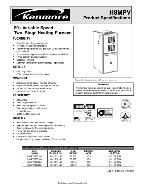
80+Variable SpeedTwo--Stage Heating Furnace FLEXIBILITY•Supports two--stage cooling units•40″high,for ease of installation•Factory shipped for natural gas,with LP gas conversion kits available•Four position--upflow/downflow/horizontal installation •Three position inducer capability•Category I venting•Common venting with other Category I appliances SERVICE•Self diagnostics•Entire blower assembly removableCOMFORT•Adjustable timed blower heating Off delay •Adjustable timed blower cooling On/Off delay •24and115VAC humidifier terminals •Electronic air cleaner terminalEFFICIENCY•80%AFUE•Two--stage operation•BPM Variable speed DC motor•Two--stage Induced draft blower•In--shot burners•California NOx approvedQUALITY•RPJ3Aluminized steel heat exchanger•High temperature limit control prevents overheating •Direct ignition with Silicon Nitride ignitor•Flame roll--out sensors standard•Louvered doors•One piece prepainted steel cabinet•Masonry chimney adapter available(Some models)Representative drawing only,some models may vary inappearance.WARNINGThis furnace is not designed for use insidemobile homes,trailers,or recreational vehicles.Such use could result in property damage,bodily injury,and/or death.THIS MODEL80.0UPFLOW/DOWNFLOW/HORIZONTAL(NATURAL GAS)Model NumberDimensionsH x W x D(In.)Input(MBTUH)EfficiencyAFUECooling Cap.@.5″W.C.H8MPV050B12C40x151/2x2950,00080% 1.5--3.0TONH8MPV075F14C40x191/8x2975,00080% 1.5--3.5TONH8MPV100J20C40x223/4x29100,00080% 2.5--5.0TONH8MPV125J20C40x223/4x29125,00080% 3.0--5.0TON44161202300(07/2006)Model Number NATURAL GAS*8MPV050B12C*8MPV075F14C*8MPV100J20C*8MPV125J20CINPUT(btuh)HI HeatLO Heat 50,00035,00075,00052,500100,00070,000125,00087,500HTG.CAP.(btuh)HI HeatLO Heat 40,00028,00061,00042,00081,00061,000101,00071,000AFUE%(ICS)80.0%80.0%80.0%80.0% NOx(Ng/J)<40<40<40<40TEMP.RISE(deg.F)HI HeatLO Heat 30--6025--5530--6025--5535--6535--6530--6025--55VOLTS/PH/HZ115/60/1115/60/1115/60/1115/60/1 MIN./MAX.VOLTAGE104/127104/127104/127104/127 RATING PLATE AMPS.9.811.714.914.9 TRANSFORMER(V.A.)40404040 GAS PIPE SIZE(IN.)1/21/21/21/2 CATEGORY I VENT SIZE4″4″4″4″COOLING CAP. 3.0TON 3.5TON 5.0TON 5.0TON FILTER SIZE(IN.)(required)14x25x114x25x116x25x1(2)16x25x1(2) SHIPPING WEIGHT(LBS.)130154174176 DIMENSIONS(in.)HEIGHT40404040 WIDTH X DEPTH151/2x281/2191/8x281/2223/4x281/2223/4x281/2 Model Number Description Used With ModelsNAHA002LP (1172959**)Natural gas to LP(propane)conversion Kit.Allows field conversion to LP(propane)gas.ALL*8MPV FURNACESNAHA002NG (1172961**)LP(Propane)to natural gas conversion kit.Allows field conversion to naturalgas.ALL*8MPV FURNACESNAHA001FF NAHA001FP External filter frame.16″x25″Side Return(All Furnaces)Bottom Return(All“F”191/8″Furnacesunder1600CFM)NAHA002FFNAHA002FPBottom return filter frame kit20″x25″.(All“J”223/4″Furnaces)NAHA003FFNAHA002FPBottom or side return filter frame kit14″x25″.(All“B”151/2″Furnaces)NAHA001TK Duct Standoff Filter Kit.To adapt20″x25″filter for single side return.Side Return(All single return applicationswith1600CFM or greater)Bottom Return(All“F”191/8″Furnacesunder1600CFM)NAHH001SB Subbase Furnace ONLY:All151/2″wide furnace models*8MPV050BNAHH002SB Subbase Furnace ONLY:All191/4″wide furnace models*8MPV075F--100FNAHH003SB Subbase Furnace ONLY:All223/4″wide furnace models*8MPV100J--125JNAHH004SB Subbase Furnace w/151/2″cased coil Counterflow furnace*8MPV050B NAHH005SB Subbase Furnace w/191/4″cased coil Counterflow furnace*8MPV075F--100F NAHH006SB Subbase Furnace w/223/4″cased coil Counterflow furnace*8MPV100J--125JNAHA001DH Chimney adapter(6″)*8MPV075,100NAHA002DH Chimney adapter(7″)*8MPV125NAHA002VC Downflow vent guard All Furnaces in the Downflow Application COIL ADAPTERNAHA001CA Coil Adapter for Downflow Furnaces All Furnaces in the Downflow Application WARNING LABEL REPLACEMENT KITNAHA002WL To replace Warning Labels,Operating Instructions&Wiring Labels on BlowerDoor when needed*8MPV*Denotes Brand**Fast part numberMODEL NUMBER IDENTIFICATION GUIDE*8M P V075B12C#Brand Engineering Rev. Brand Efficiency Denotes minor change 8=Non--Condensing,80+%Gas Furnace9=Condensing,90+%Gas Furnace Marketing Digit Installation Configuration Denotes major change UP=Upflow DN=Downflow Cooling Airflow UH=Upflow/Horizontal HZ=Horizontal08=800CFM16=1600CFM DH=Downflow/Horizontal12=1200CFM20=2000CFM MP=Multiposition,Upflow/Downflow/Horizontal14=1400CFMMajor Design Feature1=One(Single)Pipe N=Single Stage Cabinet Width 2=Two Pipe P=PVC Vent B=15.5″Wide J=22.8″Wide D=1or2Pipe T=Two Stage F=19.1″Wide L=24.5″Wide L=Low NOx V=Variable Speed Input(Nominal MBTUH) *Denotes BrandCooling Airflow Settings。

环保行业空气净化器使用说明书使用说明书一、介绍环保行业空气净化器是一种能够有效净化室内空气,提供健康、安全环境的设备。
使用本空气净化器不仅可以过滤空气中的有害物质,还能消除异味,保持空气清新。
二、安装1. 打开包装箱,取出空气净化器及附件。
2. 将空气净化器放置在离墙面一定距离的平稳台面上,确保通风良好。
3. 打开空气净化器的进气和出气口,确保没有堵塞物。
4. 将插头插入电源插座,并确保电源供应稳定。
三、使用1. 开启开关根据需要,将空气净化器的开关拨至开启状态。
空气净化器会自动开始运行。
2. 根据环境调节风速根据最佳效果,可选择不同的风速档位。
风速档位分为弱、中、强三档。
通过旋转控制开关,可以调节风速。
3. 定时功能本空气净化器配备定时功能。
通过调节定时器,用户可以设置设备运行一定时间后自动关机,最长可设置定时60分钟。
4. 滤网更换为了保证空气净化器的正常运行,滤网需要定期更换。
请根据使用说明和滤网状况来决定更换时间,并按照说明书正确更换滤网。
5. 清洁与维护定期对空气净化器进行清洁和维护,可有效延长设备寿命。
清洁方法如下:- 首先,断电并拔掉电源插头。
- 使用湿抹布轻擦外壳和显示屏,不要使用腐蚀性或有颗粒的清洁剂。
- 定期清洗滤网。
将滤网取出,用清水轻刷,然后晾干后放回。
四、注意事项1. 在使用本空气净化器之前,请务必阅读整本说明书,并按照要求正确操作。
2. 请将空气净化器放置在稳定平整的位置,避免翻倒或摔落。
3. 请勿将空气净化器放置在有火焰或易燃材料附近,以免发生火灾。
4. 请勿将外壳拆卸或触摸任何内部零件,以免发生电击或设备损坏。
5. 请勿将本设备用于其他非空气净化目的,并避免进入液体或固体物质。
6. 若发生任何故障,请立即停用空气净化器,并寻求专业维修人员的帮助。
五、维修与保养1. 在维修或保养空气净化器之前,请务必断开电源,避免电击事故。
2. 请勿私自拆卸或修理设备,以免造成设备损坏或故障。
空气净化器操作规程空气净化器是一种能够过滤和净化室内空气的设备,有效去除空气中的有害物质,提供一个清洁健康的室内环境。
为了正确使用和维护空气净化器,以下是一份空气净化器操作规程,供您参考。
一、准备工作1. 确保空气净化器的电源连接良好,并处于工作状态。
2. 检查空气净化器是否安装在通风良好的位置,并保持一定的空气流动。
3. 清理空气净化器周围的障碍物,确保无阻碍的空气进出。
二、开启空气净化器1. 按下开关按钮或遥控器上的电源开关,将空气净化器从待机状态切换到工作状态。
2. 根据个人需求,选择适当的工作模式和风速。
三、调节空气净化器1. 如果空气净化器配有风速调节功能,可根据需要调整风速。
一般而言,高风速可用于快速净化,低风速适合夜间运行。
2. 根据空气污染程度,调整空气净化器的工作模式。
例如,可以选择自动模式,让净化器根据空气质量自动调整工作强度。
四、定期检查1. 检查空气净化器的滤芯状态。
如果滤芯出现损坏或变色,应及时更换。
一般建议每3-6个月更换滤芯,具体请参考产品说明书。
2. 清理空气净化器的外壳,以确保良好的工作效果。
3. 定期检查空气净化器的电源线和插头是否正常。
五、注意事项1. 请勿在空气净化器工作时打开窗户,以免空气外流导致效果降低。
2. 请确保空气净化器远离火源,避免发生火灾。
3. 在使用空气净化器的同时,保持室内清洁,避免尘埃等污染物进入空气净化器内部。
4. 如果空气净化器发出异常声音或散发异常气味,请立即关闭并联系售后服务。
六、附加功能使用1. 如果您的空气净化器配有其他功能,如负离子发生器或加湿器等,根据需要进行合理使用。
特殊功能的使用请参考产品说明书。
2. 当需要更换滤芯或进行维护时,请按照产品说明书的指导进行操作。
七、关闭空气净化器1. 当不需要使用空气净化器时,按下电源开关按钮或遥控器上的电源开关,将其切换到待机状态。
2. 将空气净化器从电源插座上拔下插头。
八、其他注意事项在操作空气净化器过程中,请注意以下事项:1. 学习并掌握产品说明书中的所有操作细节和安全提示。
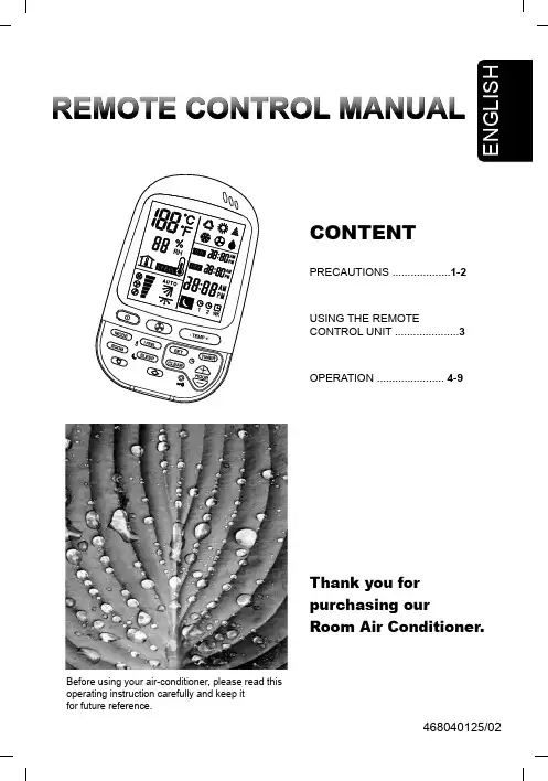
Before using your air-conditioner, please read this operating instruction carefully and keep itfor future reference.HOW TO INSTALL BATTERIES Remove the lid in the rear part of the remote control unit.Insert two AAA alkaline batteries of 1,5 V-DC.TEMPERATURE SENSOR SELECTOR Under normal conditions the room temperature is detected and checked by the temperature sensor placed in the air conditioner.OPERATION WITH THE REMOTE CONTROL UNITHOW TO TURN ON THE AIR CONDITIONER Press the ON/OFF button to turn the air conditioner on. The indicator OPERATION will light up, indicating the unit is in operation.HOW TO SET THE PRESENT TIME 1. Press the SET button for five seconds. Thetime indication alone flashes.2. Press the + or - buttons until the present timeCOOLINGVerify that the unit is connected to the main power and the STANDBY lamp is light up.1. Set the MODE selector to COOL .HEATING1. Set the MODE selector to HEAT .2. Press the ON/OFF button and switch the aircondioner ON.AUTOMATIC OPERATION1. Set the MODE selector to AUTO .2. Press the ON/OFF button and switch the aircondioner ON.DEHUMIDIFYING (DRY)1. Set the MODE selector switch to “DRY” .2. Press the ON/OFF button and switch the aircondioner ON.FAN ONLYIf you want to make air circulate without any temperature control, follow these steps:1. Set the MODE selector switch to “FAN” .ADJUSTING THE FAN SPEED AUTOMATICSimply set the FAN SPEED selector to theSLEEP MODEThe SLEEP mode enables you to save energy.1. Set the MODE selector to cool, dry or heat.2. Press the SLEEP button.LOCK FUNCTIONBy pressing LOCK button, the remote control will lock the last operation program. All the function buttons will be inoperative, includingSETTING THE TIMERThere are four timers that can be selected on the remote control.Two daily timers (designated as T1,T2) ,and two optional weekend timersI FEEL TEMP FUNCTION OPERATION Press button IFEEL to activate the IFEEL function. Thermometer sign will appear on the LCD operation display . Select suitableROOM TEMP FUNCTION OPERATION Press the ROOM button to show the actual room temperature around the remote control unit. The measured room temperature and the roomADJUSTING THE AIR FLOW DIRECTION HORIZONTAL (manual)The horizontal air flow can be adjusted by moving the vertical vanes to the left or right.。

专利产品 仿冒必究安阳振动器有限责任公司(集团)为确保产品的正确、安全使用,请在使用前仔细阅读本说明书联合制造安阳安振环境高科有限公司智能空气净化新风系统产品使用说明书产品简介◆产品简介......................................................... (1)◆使用范围......................................................... (1)◆系统组成......................................................... (1)◆技术参数......................................................... (1)使用维护◆使用注意事项......................................................... . (2)◆空气净化流程图......................................................... (4)◆操作使用说明......................................................... . (5)◆常见故障......................................................... .. (11)◆温馨提示......................................................... .. (12)◆接线图......................................................... (13)附件◆智能空气净化新风系统保修卡此标志表示禁止之事项此标志表示必须遵循事项使用注意事项使用本智能空气净化新风系统时,请注意以下事项否则会损坏新风系统。

空气净化器说明书 Document serial number【KKGB-LBS98YT-BS8CB-BSUT-BST108】专利产品 仿冒必究 安阳振动器有限责任公司(集团)为确保产品的正确、安全使用,请在使用前仔细阅读本说明书产品简介◆ 产品简介.................................................................................1 ◆ 使用范围.................................................................................1 ◆ 系统组成.................................................................................1 ◆ 技术参数 (1)使用维护◆ 使用注意事项 (2)联合制造 安阳安振环境高科有限公司 智能空气净化新风系统产品使用说明书◆空气净化流程图............................................................... (4)◆操作使用说明............................................................... . (5)◆常见故障............................................................... .. (11)◆温馨提示............................................................... .. (12)◆接线图............................................................... (13)附件◆智能空气净化新风系统保修卡此标志表示禁止之事项此标志表示必须遵循事项注:使用电源220V/50Hz使用注意事项使用本智能空气净化新风系统时,请注意以下事否则会损坏新风系统。
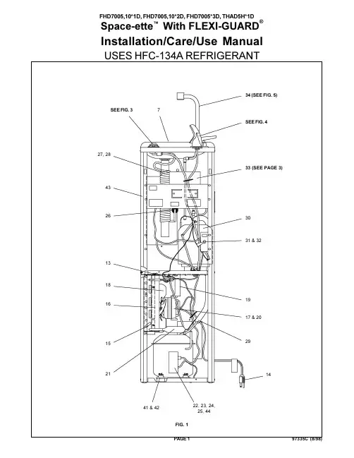
FHD7005,10*1D, FHD7005,10*2D, FHD7005*3D, THAD5H*1DSpace-etteWith FLEXI-GUARD®Installation/Care/Use ManualUSES HFC-134A REFRIGERANTFIG. 134 (SEE FIG. 5)SEE FIG. 372614SEE FIG. 443181627, 281541 & 4222, 23, 24,25, 4431 & 321333 (SEE PAGE 3)301917 & 202921FIG . 2FINISHED FLOOR PISO ACABADO PLANCHER FINILEGEND/LEYENDA/LÉGENDEA = RECOMMENDED WATER SUPPLY LOCATION 3/8 O.D. UNPLATED COPPER TUBE CONNECT STUB 1-1/2" (38mm) OUT FROMWALL SHUT OFF BY OTHERSSE RECOMIENDA UBICAR EL TUBO DE CONEXIÓN AL TUBO DE COBRE SIN CHAP AR DE 3/8" DE DIAM. EXT. A 1-1/2" (38mm) FUERA DE LA LLAVA DE P ASO EN LA P ARED COLOCADA POR TERCEROS.EMPLACEMENT RECOMMANDÉ D ALIMENTATION EN EAU P AR TUBE EN CUIVRE NON PLAQUÉ DE 3/8 PO. (9,5mm) D.E.CONNECTANT UNE TUYAUTERIE DE 1-1/2 PO. (38mm) DEPUIS LE ROBINET D'ARRET FOURNI P AR D'AUTRES.B = RECOMMENDED LOCATION FOR WASTE OUTLET 1-1/4 O.D. DRAINUBICACIÓN RECOMENDADA P ARA EL DRENAJE DE SALIDA DE AGUA, DE 1-1/4" DE DIÁMETRO.EMPLACEMENT RECOMMANDÉ POUR LE DRAIN DE D.E. 1-1/4" DE SORTIE D EAU.C = 1-1/4 TRAP NOT FURNISHEDPURGADOR DE 1-1/4 NO PROPORCIONADO SIPHON 1-1/4 NON FOURNID = INSURE PROPER VENTILATION BY MAINTAINING 4" (102mm) (MIN.) CLEARANCE FROM CABINET LOUVERS TO WALL.ASEGURE UNA VENTILACIÓN ADECUADA MANTENIENDO UN ESP ACIO E 4" (102mm) (MÍN.) DE HOLGURA ENTRE LA REJILLA DE VENTILACIÓN DEL MUEBLE Y LA P AREDASSUREZ-VOUS UNE BONNE VENTILATION EN GARDANT 4" (102mm) (MIN.) ENTRE LES ÉVENTS DE L ENCEINTE ET LE MUR.E = POWER CORD 4 FEET (1219mm) LONGCABLE ELÉCTRICO DE 4 PIE (1219mm), DE LARGO CORDON D ALIMENTATION 4' (1219mm)Stream height is factory set at 35 PSI. If supply pressure varies greatly from this, remove Items 1 & 2 and adjust screw on Item 4. Clockwise adjustment will raise stream and counter-clockwise adjustment will lower stream. For best adjustment,stream should hit basin approximately 6-1/2" (165mm) from bubbler.BASINFIG. 3NOTE:WHEN INST ALLING REPLACEMENTBUBBLER AND PEDESTAL, TIGHTEN NUT (ITEM 12) ONLY TO HOLD PARTS SNUG IN POSITION. DO NOT OVER TIGHTEN.FIG. 4BASIN 91011128431562WIRING DIAGRAMThis Drawing is merely for illustrating the components of the electrical system.22111C 22112C 22113C 30980C 31386C 31428C 50787C 70606C 70607C 70640C 70659C 70683C 70793C 22588C12345678910111213NSPART. NO.DESCRIPTIONITEM NO.HOT TANK PARTS LISTHeater Clamping BracketHeater Clamping Bracket (thrd)Retaining BracketHeater Element & Jacket Tank & Tube Assy Hot Control Assy Washer-Spacer Drain PlugScrew 1/4-20 x 3.00" HSHC Screw #8-18 x 5/16" HHTC Belleville Washer 1/4 Union 1/4 ElbowHot Tank Mounting BracketFIG. 5353638403739SERVICING THE HOT CONTROL AND FUSE ASSEMBLY1. A temperature sensing non-resetable fuse in the wire is located approximately 3" (76mm) from the thermostat. The fuse is located under the retaining bracket (Item 3) in the groove on the heater element jacket (Item 4).2. The thermostat must be used with a washer-spacer (Item 7) and be centered in the heater element jacket for proper temperature control. Locate the heater element jacket about 3/4" (19mm) above the bottom of the tank.3. The heater element jacket must be fastened VERY TIGHTLY to the tank (45+/-10 inch-lbs. of torque on the mounting screw Item 9). Failure to TIGHTEN heater element jacket may cause rapid failure of the fuse assembly.10367911128134512PRINTED IN U.S.A.*REPLACE WITH SAME COMPRESSOR USED IN ORIGINALASSEMBLY . NOTE: All correspondence pertaining to ELKAY water coolers or orders for repair parts MUST include Model No. and Serial No.of cooler, name and part number of replacement part.DESCRIPTION40089C 40048C 15005C 61313C 40169C 50986C 22546C 51349C 40322C 50934C 50168C 70012C 31513C 31495C 66303C 66304C 50189C 31490C 30664C 20282C 70018C 66200C 66202C 35786C 35947C 31038C 31039C 35766C 35768C 19424390155055996C 40570C 55835C 66300C 66508C 66504C 66505C 21591C 30010C 31405C 40582C 40597C 92712C 51543C 40596C 70921C 3365900050144C 70418C 21486C 21239C 35935C 21482C 20460C 55832C12345678910111213141516171819202122*22a*2323a 2424a 252627282929a 3030a 3132333435363738394041424344a NS NSP ART NO.Cover ButtonRegulator Retaining Nut Regulator Hex NutRegulator HolderBasin & Precooler Assy Bubbler Assy Orifice Assy Housing Assy PedestalBubbler Locknut Cold Control Power CordCondenser (5GPH)Condenser (10GPH)Fan Shroud Fan Motor Fan Blade Fan Bracket Fan Blade Nut Drier (5GPH)Drier (10GPH)Compressor Serv. Pak PW3HK7 (5GPH)Compressor Serv. Pak EM65 (10GPH)Overload/Relay Assy 1.350.398 (5GPH)Overload/Relay Assy P600B/427NFBYY (10GPH)Cover - Relay (5GPH)Cover - Relay (10GPH)Electrical Shield StrainerPrecooler Assy T ailpipe HelixHeat Exchanger (5GPH)Heat Exchanger (10GPH)Evaporator (5GPH)Evaporator (10GPH)Hot Tank Switch Bracket Hot T ank Switch Hot T ank Assy Hot Valve Assy Gooseneck Hot Valve Kit Handle ShroudMounting Nut Body GasketGrommet-Compressor Washer-Compressor Cabinet-Sandalwood Cabinet-Stainless Steel Capacitor - Run (10GPH)Front Panel-Sandalwood Front Panel-Stainless Steel Flow Regulator AssyITEM NO.PARTS LIST 115VDESCRIPTION31430C 35788C 35763C 31035C 31024C 35768C 31406C17*22*22a 2323a 2433PART NO.Fan MotorCompressor Serv Pak (5 GPH)Compressor Serv Pak (10 GPH)Overload/Relay Assy (5 GPH)Overload/Relay Assy (10 GPH)Relay Cover (10 GPH)Hot Tank AssyITEM NO.PARTS LIST 230V-50/60Hz 800-518-5388。
空气净化器产品说明书提供健康的室内空气呵护您的呼吸健康产品说明书 - 空气净化器一、产品介绍本产品是一款高效的空气净化器,旨在提供健康的室内空气,保护您的呼吸健康。
它采用先进的空气净化技术,能够有效去除室内的有害气体、细菌和颗粒物,为您创造一个清新、洁净的室内环境。
二、产品特点1. 高效净化:本空气净化器配备了强大的过滤系统,可去除空气中的PM2.5、甲醛、苯等有害物质,保证室内空气质量达到国家标准。
2. 智能感知:采用先进的传感器技术,能够实时监测室内空气质量,并根据情况自动调节净化器的工作模式,确保持续有效地净化空气。
3. 低噪音设计:本产品采用静音技术,运行时噪音低于30分贝,不会给您的生活带来任何干扰。
4. 节能环保:采用高效的能源管理系统,功耗低,能够持续稳定地工作,并且符合环保要求。
5. 便捷搭载:小巧轻便的设计,方便携带和安装,可以在家庭、办公室、车辆等各种场景中使用。
三、操作指南1. 插电并打开电源开关。
2. 在操作面板上选择合适的净化模式,如自动模式、睡眠模式、强力模式等。
3. 室内空气质量显示屏会实时反映当前的空气质量状况。
4. 按下开机键后,空气净化器将开始工作,同时能量指示灯亮起。
5. 定期清洁和更换过滤器,以确保净化器的长久性能。
四、注意事项1. 请不要将本产品放置在高温或潮湿的环境中,以免影响正常使用。
2. 请确保电源插座与产品适配,避免电源过载或短路。
3. 定期清洁产品表面,避免灰尘和污渍影响净化效果。
4. 请放置在儿童无法触及的地方使用,以防意外发生。
5. 建议按照说明书提供的清洁和维护建议进行操作,以保持产品的最佳性能。
五、售后服务1. 本产品享受一年的质保期,如出现质量问题,请及时联系售后服务中心进行处理。
2. 售后服务热线:XXXX-XXXXXXX,工作时间:周一至周五,9:00-18:00。
六、结语感谢您选择我们的空气净化器产品。
我们将持续努力提供高品质的产品和优质的服务,为您的家庭和工作环境提供洁净、健康的室内空气。
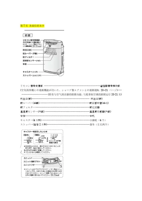
第7页各部位的名字リモコン信号受信部-------------------------------------------------------------------遥控器信号接收部(空気清浄機との連動機能が付いた、シャープ製エアコンとの連動運転20~21ページ)----- ------------------------------- (附有与空气清洁器的联锁功能,与夏普制空调的联锁运行20-21页) 吹出口(前)--------------------------------------------------------------------- 吹出口(前)前ルーバー(手動) -----------------------------------------------------------前面百叶窗(手动)前フィルター-----------------------------------------------------------------前过滤器温湿度センサー(内部) -----------------------------------------------------温湿度传感器(内部)本体-----------------------------------------------------------------------------本机キャスター(4カ所) ---------------------------------------------------------小脚轮(4个)ストッパー(左右2カ所)---------------------------------------------------刹车(左右两个)想固定小脚轮时固定----------------向下按解除----------------向上拉或者横向推刹车下侧●在安全性上,操纵需要用力。
产品说明书空气净化器产品说明书:空气净化器一、产品概述空气净化器是一种用于净化室内空气的电器设备。
它通过吸入空气并经过多重过滤系统,去除空气中的颗粒物、异味和有害气体,从而提供清新健康的室内空气环境。
本产品说明书将详细介绍空气净化器的特点、使用方法和注意事项。
二、产品特点1. 多重过滤系统:本空气净化器采用了高效HEPA过滤器、活性炭过滤器和静电除尘器等多种过滤技术,能够有效去除空气中的细菌、病毒、尘螨、花粉等有害物质。
2. 智能感知:配备了先进的空气质量传感器,能够实时监测室内空气质量,并根据需要自动调节工作模式,确保室内空气始终清新。
3. 低噪音设计:采用静音技术,运行噪音低于30分贝,不会对您的休息、学习和工作造成干扰。
4. 智能控制:支持手机APP远程控制,您可以通过手机随时随地调整空气净化器的运行模式和风速,享受便捷的使用体验。
5. 省电节能:采用高效节能电机和智能省电控制系统,能够有效降低能耗,节约用电成本。
三、使用方法1. 安装:将空气净化器放置在通风良好的位置,确保周围没有遮挡物。
连接电源后,按照说明书正确安装过滤器。
2. 开机:插上电源后,按下电源开关,空气净化器将开始工作。
此时,您可以选择自动模式或手动模式。
3. 自动模式:在自动模式下,空气净化器会根据室内空气质量自动调节工作模式和风速。
您只需设置合适的目标空气质量,空气净化器将自动工作。
4. 手动模式:在手动模式下,您可以根据需要选择不同的风速档位,或者选择特定的工作模式,如睡眠模式、节能模式等。
5. 定期更换过滤器:根据使用情况,建议每3-6个月更换一次过滤器,以确保空气净化器的净化效果和运行效率。
四、注意事项1. 请勿将空气净化器放置在潮湿或有水源的地方,以免发生电器故障或人身伤害。
2. 使用过程中请勿拆卸或更换内部零部件,以免损坏设备或引起安全隐患。
3. 定期清洁外壳和过滤器,以保持空气净化器的工作效果和外观整洁。
4. 当您长时间不使用空气净化器时,请将其断电并拔掉电源插头。
家用空气净化器操作手册一、简介家用空气净化器是一种能够净化室内空气,提供健康安全环境的电器设备。
本操作手册旨在帮助用户正确操作和使用家用空气净化器,以获得更好的空气质量和使用体验。
二、净化器外观及部件1. 外观家用空气净化器外观一般由主机、控制面板、空气出风口等部分组成。
主机通常为方形或圆柱形状,具有美观大方的设计。
2. 控制面板控制面板用于设置净化器的工作模式、调节风速等。
常见的控制按钮和显示器包括开/关机按钮、风速调节按钮、定时设置按钮、工作模式设置按钮等。
3. 空气出风口空气出风口用于释放被净化后的空气,通常位于净化器的正面或侧面。
三、净化器使用步骤1. 确定使用场所在选择使用家用空气净化器前,需要考虑使用的场所大小和污染程度。
一般来说,较小的空间可选择较小功率的净化器,而较大的空间则需要选择功率较大的净化器。
2. 连接电源将净化器的电源线插入电源插座,并确保电源供应正常。
如果家用空气净化器配备有电池,也可以选择使用电池供电。
3. 控制面板设置根据自身需求,设置工作模式、风速、定时等功能。
通常可以选择自动模式、静音模式、强力模式等不同工作模式。
4. 开启净化器按下开/关机按钮开启净化器。
净化器开始工作时,可以听到风机运转的声音。
5. 调整风速根据需要,可适时调整净化器的风速。
较高的风速能够更快速地净化室内空气,而较低的风速则更为安静舒适。
6. 定时设置若需要在特定时间段内自动关闭净化器,可设置定时功能。
净化器会在设定的时间到达后自动关闭。
四、净化器维护与清洁1. 定期更换滤芯滤芯是空气净化器的核心部件,需要定期更换以保证净化效果。
一般情况下,滤芯建议每3-6个月更换一次,具体时间可根据使用环境和使用频率进行调整。
2. 清洁净化器外壳定期使用干净柔软的布清洁净化器外壳,并避免使用含有酸性和腐蚀性的清洁剂。
确保净化器外观整洁,不影响美观和运行效率。
3. 注意安全使用在清洁净化器或更换滤芯时,务必先拔掉电源插头,避免触电和其他安全问题。
Installation Instructions NOTE:Read the entire instruction manual before starting theinstallation.SAFETY CONSIDERATIONSInstallation and servicing of this equipment can be hazardous dueto mechanical and electrical components.Only trained andqualified personnel should install,repair,or service thisequipment.Untrained personnel can perform basic maintenance functionssuch as cleaning and replacing air filters.All other operationsmust be performed by trained service personnel.When workingon this equipment,observe precautions in the literature,on tags,and on labels attached to or shipped with the unit and other safetyprecautions that may apply.Follow all safety codes.Installation must be in compliance withlocal and national building codes.Wear safety glasses,protectiveclothing,and work gloves.Have fire extinguisher available.Readthese instructions thoroughly and follow all warnings or cautionsincluded in literature and attached to the unit.Recognize safety information.This is the safety--alertsymbol.When you see this symbol on the unit and in instructions or manuals,be alert to the potential for personal injury.Understand these signal words;DANGER,WARNING,and CAUTION. These words are used with the safety--alert symbol.DANGER identifies the most serious hazards which will result in severe personal injury or death.WARNING signifies hazards which could result in personal injury or death.CAUTION is used to identify unsafe practices which may result in minor personal injury or product and property damage.NOTE is used to highlight suggestions which will result in enhanced installation, reliability,or operation.Follow all safety codes.Wear safety glasses and work gloves. Have a fire extinguisher available.Fig.1--Low NOx Baffle LocationThese instructions cover the installation of a propane conversion kit on models 48GS,582A,PY1P--B,48GX,583A,PY2P--B,48GP,583B,48JZ,683B,48XP,574B,48XZ,674B,48SD,574A,PY3P,48CE,574C,48SZ,674A,48ES,574D,48EZ,and 674D that are equipped with a White Rodgers combination automatic gas valve regulator.DESCRIPTION AND USAGEThis kit is applicable to units with heating inputs from 40,000to installed at altitudes up to 6000ft.For units with heating inputs from 60,000Btu/hr to 130,000Btu/hr use propane conversion kit CPLPCONV006A00(for 0ft--2000ft)or CPLPCONV007A00(for 2001ft --6000ft.)INSTALLATION1.Turn off gas supply first,then power to unit.2.Remove the front access panel from unit.3.Disconnect the gas pipe from the gas valve.4.Disconnect orange sparker cable from the sparker .5.Disconnect yellow flame sensor wire from the flame sensor.6.Remove the screw securing the brown wire from the burner assembly and the green wire form the induced--draft motor at the sheet metal partition.Savescrew.7.Disconnect the gray and brown wires from the gas valve,and remove blue wires from the rollout switch.Table 1–Kit ContentsITEMQUANTITYPropane Gas Orifice #50*3Propane Gas Orifice #523Burner Insert 2Pressure Switch 1Nipple,2--in.1Nipple,2--1/2in.190_Elbow,1/8--in.2Close Pipe Nipple 1Wire Assembly1Propane Conversion Label (Rating Plate)1Propane Conversion Label (InstallerResponsibility)1Propane Conversion Warning Label (Gas Valve)1*Refer to Table 2to determine the correct orifice to use.8.Remove the screw attaching the gas manifold to the basepan,and slide out the entire burner rack assembly from unit.Save screw.9.Inspect the inlet of the heat exchanger tubes for presence of V--shaped NOx baffles (see Fig.1).If baffles are present they must be removed prior to converting unit for propane gas.Slide the baffles out of the tubes (on some models a retaining clip must be released).Table 2–Propane Gas Orifice SizesUNIT SIZES PROPANE NOMINAL HEATING INPUT(BTUH)NUMBER OF ORIFICESGAS SUPPL Y PRESSURE (IN.WC)(PROPANE)MANIFOLD PRESSURE (IN.WC)(PROPANE)PROPANE GAS ORIFICE PART NO.ANDSIZE ALTITUDE (FT)MINMAX 0---20002001---600001804002404003004040,00027.013.03.5LH32RF070No.50LH32RF065No.5202406003006003606004206057,000THIS KIT APPLIES TO 40,000BTUH MODELS ONLY .FOR ALL OTHER UNIT SIZES USE THE FOLLOWING KIT PART NUMBERS:CPLPCONV006A00---STANDARD ALTITUDE PROPANE CONVERSION KIT (0---2000FT)CPLPCONV007A00---HIGH ALTITUDE PROPANE CONVERSION KIT (2000---6000FT)03609004209004809006009085,500048115060115115,000048130060130127,000IMPORTANT :If it is expected that this unit will be converted back to natural gas at a later time,these baffles should be retained for reuse.Otherwise the baffles may be discarded.ing a 5/16in.nut driver,remove the four screwssecuring the manifold/gas valve assembly to the burner assembly.Save these screws.11.Remove the natural gas orifices from the manifold using a9/16in.wrench and install the correct propane gas orifices in the manifold.See Table 2to select correct orifice size based on input.See Fig.2for orifice installation.12.Remove the two burners from the rack,save the screws.Remove the snap ring from the end of each burner.Install burner insert in the end of each burner with the flat sides of the square vertical and horizontal.Replace the snap ring to retain burner insert (See Fig.2for correct orientation).Replace the burners in the rack using the saved screws,making sure closed crossovers of burners are at each end.13.Replace the manifold/gas valve assembly into the burnerassembly using the four screws saved from Step 10.14.Remove the plug on the inlet end of the gas valve using a3/16in.hex wrench.15.Install the 1/8in.close pipe where the plug was removed.(See Fig.4.)Use sealant (field--supplied),making sure notto get any excess in the pipe or valve.Next,install a 1/8in.elbow,a 1/8in x 2--1/2in.nipple,1/8in.x 2in.nipple,and pressure switch as shown in Fig.4.16.Install the 6in gray wire (in kit)on terminal 1(M1)onthe main gas valve and to the pressure switch (See Fig.5.)17.Reconnect the blue wires to the rollout switch and reinstallrollout switch.18.Reconnect the gray wire removed form the gas valve inStep 7to the other terminal on the pressure switch.Recconect the brown wire,removed in Step 7,to terminal 2(C2)on the main gas valve.19.Reconnect orange sparker cable and the yellow flamesensor wire at the ignition control.20.Slide burner rack assembly into basepan.Align burnerrack with sdcrews on sheet metal partition and slideassembly back tight to the partition.Replace the screw attaching the burner rack into the basepan,removed in Step 8.21.Reconnect the brown wire from the burner assembly andthe green wire from the induced--draft motor to the sheetmetal partition.22.Remove the 1/8in.pipe plug on the gas manifold andconnect a pressure manometer.23.Reconnect electrical power and gas supply to the unit.24.Fire unit and verify proper ignition.Verify that thepressure reads 3.5in. 0.3in.wc.If thepressure is outside this range,adjust the gas valve setting by removing the slotted brass fitting and turning the nylon adjustment screw.Replace brass fitting.25.Turn off unit,remove pressure manometer and replace the1/8in.pipe fitting on the gas manifold .26.Attach warning label (P/N 48GS500615)to visible side ofgas valve.27.Attach conversion label (P/N 48GS500614)above unitrating plate on exterior of unit.28.Attach completed conversion responsibility label (see Fig.3,P/N 48SS500283)inside service access panel.IMPORTANT :Restart unit and leak check all gas connections including the main service connection,gas valve,gas spuds,manifold pipe plug and pressure switch.C00148PIPE PLUGC00148Fig.2--Orifice InstallationTHIS APPLIANCE HAS BEEN CONVERTEDTO LP . GAS. KIT NO. _______________________BY _______________________ DATE: ________WHO ACCEPTS THE RESPONSIBILITY FOR THE CORRECTNESS OF THIS CONVERSION.48SS500283A99309Fig.3--Conversion Responsibility Label1/8"ELBOWSWITCHNIPPLEELBOWA99310Fig.4--Installing Elbows,Nipples,and Pressure SwitchLEGENDGV –Gas ValveMGV –Main Gas ValveA99311Fig.5--Pressure Switch WiringCopyright 2007CAC /BDP D 7310W.Morris St.D Indianapolis,IN 46231Manufacturer reserves the right to change,at any time,specifications and designs without notice and without obligations.Catalog No:IIKCPLPCONV---07Replaces:IIK 582A--18--9Printed in U.S.A.Edition Date:02/07。
AC4373AC4375用户手册扫描二维码,按照屏幕上的说明进行下一步操作。
或目录1 重要事项12安全12 2 您的空气净化器13总体说明14 3 使用入门15安装过滤网15首次设置 Wi-Fi 连接16在网络已更改时设置 Wi-Fi连接17 4 使用空气净化器18开启空气净化器18了解空气质量指示灯19设置空气质量感应器的灵敏度19选择风速20设置定时器20启用儿童锁21夜间模式21打开或关闭 Wi-Fi 21出厂重置22 5 清洁空气净化器23清洁空气净化器23清洁空气质量感应器236 清洁预过滤网257 更换过滤网27重置过滤网锁29 8 故障排除309 保修与服务32订购部件或附件32 10 注意事项32电磁场 (EMF) 32回收321 重要事项安全使用产品前请仔细阅读本使用说明书,并妥善保管以备日后参考。
危险•切勿让水或任何其它液体或易燃性清洁剂进入产品,以免发生触电和/或火灾。
•切勿用水或任何其它液体或(易燃性)清洁剂来清洁产品,以免发生触电和/或火灾。
警告•在将产品接通电源以前,首先确认产品背面或底部所标示的电压是否与当地的电压相符。
•如果电源软线损坏,为避免危险,必须由制造厂或其维修部或类似的专职人员来更换。
•如果插头、电源线或产品本身受损,请勿再使用本产品。
•本产品不打算由肢体不健全、感觉或精神上有障碍或缺乏相关经验和知识的人(包括儿童)使用,除非有负责他们安全的人对他们使用本产品进行监督或指导。
•应照看好儿童,避免他们玩耍本产品。
•不要让儿童在无人监督的情况下进行清洁和保养。
•请勿堵塞进风和出风口,例如不要将物体放置在出风口上或进风口前方。
注意•本产品不能替代正常通风、日常吸尘或者在烹饪时使用的抽油烟机。
•如果连接产品的电源插座接触不良,则产品的插头可能会变得很热。
确保所连接的电源插座接触良好。
•一定要在干燥、稳固、平整且水平的表面上放置和使用本产品。
•产品的后侧及两侧均要留出至少20 厘米的空间,产品上方至少要留出 30 厘米的空间。