基于模糊控制的移动机器人的外文翻译
- 格式:doc
- 大小:3.83 MB
- 文档页数:23

外文资料FUZZY LOGIC CONTROL FOR ROBOT MAZE TRA VERSAL: ANUNDERGRADUATE CASE STUDYJames Wolfer Chad A. GeorgeAbstractAs previously reported, Indiana University South Bend has deployed autonomous robots in their Computer Organization course to facilitate introducing computer science students to the basics of logic, embedded systems, and assembly language. The robots help to provide effective, real-time feedback on program operation and to make assembly language less abstract. As a part of their coursework students are required to program a sensor-based traversal of a maze. This paper details one solution to this problem employing a fuzzy logic controller to create linguistic rules.Key words:Fuzzy logic, pedagogy, robots, student projectsINTRODUCTIONAssembly language programming in a computer science environment is often taught using abstract exercises to illustrate concepts and encourage student proficiency.To augment this approach we have elected to provide hands-on, real-world experience to our students by introducing robots into our assembly language class.Observing the physical action of robots can generate valuable feedback and have real-world consequences – robots hitting walls make students instantly aware of program errors, for example.It also provides insight into the realities of physical machines such as motor control, sensor calibration, and noise. To help provide a meaningful experience for our computer organization students, we reviewed the course with the following objectives in mind:• Expand the experience of our students in a manner that enhances the student's insight, provides a hands-on, visual, environment for them to learn, and forms an integrated component for future classes.•Remove some of the abstraction inherent in the assembly language class. Specifically, to help enhance the error detection environment.• Provide a kinesthetic aspect to our pedagogy.• Build student expertise early in their program that could lead to research projects and advanced classroom activities later in their program. Specifically, in this case, to build expertise to support later coursework in intelligent systems and robotics.As one component in meeting these objectives we, in cooperation with the Computer Science department, the Intelligent Systems Laboratory, and the University Center for Excellence in Teaching, designed a robotics laboratory to support the assembly language portion of the computer organization class as described in [1].The balance of this report describes one example project resulting from this environment. Specifically, we describe the results of a student project developing an assembly language fuzzy engine, membership function creation, fuzzy controller, and resulting robot behavior in a Linux-based environment.We also describe subsequent software devlopment in C# under Windows, including graphical membership tuning, real-time display of sensor activation, and fuzzy controller system response. Collectively these tools allow for robust controller development, assemblylanguage support, and an environment suitable for effective classroom and publicdisplay.BACKGROUNDRobots have long been recognized for their potential educational utility, with examples ranging from abstract, simulated, robots, such as Karel[2] and Turtle[3] for teaching programming and geometry respectively, to competitive events such as robotic soccer tournaments[4].As the cost of robotics hardware has decreased their migration into the classroom has accelerated [5, 6]. Driven by the combined goals for this class and the future research objectives, as well as software availability, we chose to use off-the-shelf, Khepera II, robots from K-Team[7].SIMULATED ROBOT DIAGRAMThe K-Team Kephera II is a small, two-motor robot which uses differential wheel speed for steering. Figure 1 shows a functional diagram of the robot. In addition to thetwo motors it includes a series of eight infrared sensors, six along the “front” and two in the “back”of the robot. This robot also comes with an embedded system-call library, a variety of development tools, and the availability of several simulators. The embedded code in the Khepera robots includes a relatively simple, but adequate, command level interface which communicates with the host via a standard serial port. This allows students to write their programs using the host instruction set (Intel Pentium in this case), send commands, and receive responses such as sensor values, motor speed and relative wheel position.We also chose to provide a Linux-based programming environment to our students by adapting and remastering the Knoppix Linux distribution [9]. Our custom distribution supplemented Knoppix with modified simulators for the Khepera, the interface library (including source code),manuals, and assembler documentation. Collectively, this provides a complete development platform.The SIM Kheperasimulator[8] includes source code in C, and provides a workable subset of the native robot command language. It also has the ability to redirect input and output to the physical robot from the graphics display. Figure 2 shows the simulated Khepera robot in a maze environment and Figure 3 shows an actual Khepera in a physical maze. To provide a seamless interface to the simulator and robots we modified the original simulator to more effectively communicate through a pair of Linuxpipes, and we developed a small custom subroutine library callable from the student's assembly language programs.Assignments for the class range from initial C assignments to call the robot routines to assembly language assignments culminating in the robot traversing the maze. FUZZY CONTROLLEROne approach to robot control, fuzzy logic, attempts to encapsulate important aspects of human decision making. By forming a representation tolerant of vague, imprecise, ambiguous, and perhaps missing information fuzzy logic enhances the ability to deal with real-world problems. Furthermore, by empirically modeling a system engineering experience and intuition can be incorporated into a final design.Typical fuzzy controller design [10] consists of:• Defining the control objectives and criteria• Determining the input and output relationships• Creating fuzzy membership functions, along withsubsequent rules, to encapsulate a solution fromintput to output.• Apply necessary input/output conditioning• Test, evaluate, and tune the resulting system.Figure 4 illustrates the conversion from sensor input to a fuzzy-linguistic value. Given three fuzzy possibilities, …too close‟, …too far‟, and …just right‟, along with a sensor reading we can ascertain the degree to which the sensor reading belongs to each of these fuzzy terms. Note that while Figure 4 illustrates a triangular membership set, trapezoids and other shapes are also common.Once the inputs are mapped to their corresponding fuzzy sets the fuzzy attributes are used, expert system style, to trigger rules governing the consequent actions, in this case, of the robot.For example, a series of rules for a robot may include:• If left-sensor is too close and right sensor is too far then turn right.• If left sensor is just right and forward sensor is too far then drive straight.• If left sensor is too far and forward sensor is too far then turn left.• If forward sensor is close then turn right sharply.The logical operators …and‟, …or‟, and …not‟ are calculated as follows: …and‟ represents set intersection and is calculated as the minimum value, …or‟ is calculated as the maximum value or the union of the sets, and …not‟ finds the inverse of the set, calculated as 1.0-fitness.Once inputs have been processed and rules applied, the resulting fuzzy actions must be mapped to real-world control outputs. Figure 5 illustrates this process. Here output is computed as the coordinate of the centroid of the aggregate area of the individual membership sets along the horizontal axis.ASSEMBLY LANGUAGE IMPLEMENTATIONTwo implementations of the fuzzy robot controller were produced. The first was written in assembly language for the Intel cpu architecture under the Linux operating system, the second in C# under Windows to provide a visually intuitive interface for membership set design and public demonstration.Figure 6 shows an excerpt of pseudo-assembly language program. The actual program consists of approximately eight hundred lines of hand-coded assembly language. In the assembly language program subroutine calls are structured with parameters pushed onto the stack. Note that the code for pushing parameters has been edited from this example to conserve space and to illustrate the overall role of the controller. In this code-fragment the …open_pipes‟ routine establishes contact with the simulator or robot. Once communication is established, a continous loop obtains sensor values, encodes them as fuzzy inputs, interprets them through the rule base to linguistic output members which are then converted to control outputs which are sent to the robot. The bulk of the remaining code implements the fuzzy engine itself.FUZZY CONTROLLER MAIN LOOPMembership sets were manually defined to allow the robot to detect and track walls, avoid barriers, and negotiate void spaces in it field of operation. Using this controller, both the simulated robot and the actual Khepera successfully traversed a variety of maze configurations.ASSEMBLY LANGUAGE OBSERV ATIONSWhile implementing the input fuzzification and output defuzzification in assembly language was tedious compared with the same task in a high level language, the logic engine proved to be well suited to description in assembly language.The logic rules were defined in a type of psuedo-code using …and‟, …or‟, …not‟ as operators and using the fuzzy input and output membership sets as parameters. With the addition of input, output and flow control operators, the assembly language logic engine simply had to evaluate these psuedo-code expressions in order to map fuzzy inputs memberships to fuzzy output memberships.Other than storing the current membership fitness values from the inputfuzzyfication, the only data structure needed for the logic engine is a stack to hold intermediate calculations. This is convenient under assembly language since the CPUs stack is immediately available as well as the nescesary stack operators.There were seven commands implemented by the logic rule interpreter: IN, OUT, AND, OR, NOT, DONE, and EXIT.•IN – reads the current fitness from an input membership set and places the value on the stack.•OUT – assigns the value on the top of the stack as the fitness value of an output membership set if it is greater than the existing fitness value for that set.•AND – performs the intersection operation by replacing the top two elements on the stack with the minimum element.•OR – performs the union operation by replace the top two elements on the stack with their maximum.•NOT – replaces the top value on the stack with its compliment.•DONE – pops the top value off the stack to prepare for the next rule•EXIT – signals the end of the logic rule definition and exits the interpreter.As an example the logic rule “If left-sensor is too close and right sensor is too far then turn right”, might be define d by the following fuzzy logic psuedo-code: IN, left_sensor[ TOO_CLOSE ]IN, right_sensor[ TOO_FAR ] ANDOUT, left_wheel[ FWD ]OUT, right_wheel[ STOP ]DONEEXITBy utilizing the existing CPU stack and implementing the logic engine as anpsuedo-code interpreter, the assembly language version is capable of handling arbitrarily complicated fuzzy rules composed of the simple logical operators provided. IMPLEMENTATIONWhile the assembly language programming was the original focus of the project, ultimately we felt that a more polished user interface was desirable for membership set design, fuzzy rule definition, and controller response monitoring. To provide these facilities the fuzzy controller was reimplemented in C# under Windows. through 10 illustrate the capabilities of the resulting software. Specifically, Figure 7 illustrates user interface for membership defination, in this case …near‟. Figure 8 illustrates theinterface for defining the actual fuzzy rules. Figure 9 profiles the output response with respect to a series of simulated inputs. Finally, real-time monitoring of the system is also implemented as illustrated in 10 which shows the robot sensor input values.Since the Khepera simulator was operating system specific, the C# program controls the robot directly. Again, the robot was successful at navigating the maze using a controller specified with this interface.SUMMARYTo summarize, we have developed a student-centric development environment for teaching assembly language programming. As one illustration of its potential we profiled a project implementing a fuzzy-logic engine and controller, along with a subsequent implementation in the C# programming language. Together these projects help to illustrate the viability of a robot-enhanced environment for assembly language programming.REFERENCES[1] Wolfer, J &Rababaah, H. R. A., “Creating a Hands-On Robot Environment for Teaching Assembly Language Programming”, Global Conference on Engineering and Technology Education, 2005[2] Pattic R.E., Karel the Robot: a gentle introduction to the art of programming, 2nd edition. Wiley, 1994[3] Abelson H. and diSessa A., Turtle geometry: the computer as a medium for exploring mathematics. MIT Press, 1996[4] Amirijoo M., Tesanovic A., and Nadjm-Tehrani S., “Raising motivation in real-time laboratories: the soccer scenario” in SIGCSE Technical Symposium on Computer Sciences Education, pp. 265-269, 2004.[5] Epp E.C., “Robot control and embedded systems on inexpensive linux platforms workshop,” in SIGCSE Technical Symposium on Computer Science Education, p. 505, 2004[6] Fagin B. and Merkle L., “Measuring the effectiveness of robots in teaching computer science,” in SIGCSE Technical Symposium on Computer Science Education, PP. 307-311, 2003.[7] K-Team Khepera Robots, , accessed 09/06/05.[8] Michel O., “Khepera Simulator package version 2.0: Freeware mobile robot simulator written at the university of nice Sophia-Antipolis by Olivier Michel. Downloadable from the world wide web. http://diwww.epfl.ch/lami/team/michel/khep-sim, accessed 09/06/05.[9] Knoppix Official Site, , accessed 09/06/05.[10] Earl Cox., The Fuzzy Systems Handbook, Academic Press, New York, 1999.模糊逻辑控制机器人走迷宫James Wolfer Chad A. George摘要美国印第安纳大学南本德已部署在他们的计算机组织课程自主机器人,以方便学生介绍计算机科学逻辑的基础知识,嵌入式系统和汇编语言。
基于模糊神经网络的移动机器人在未知环境下的实时反应摘要本文在以模糊推理和神经网络系统结合的基础上,为实现移动机器人和未知环境下的实时自反映,提出了一种混合型智能方法。
模糊推理(模糊神经网络,FNN)下的神经网络系统可以有效提高神经网络的学习速度。
此方法可用来实时控制基于当前运作情况的移动机器人。
这些情况包括由超声波传感器支持下的机器人与障碍物之间的不同方向上的距离。
目标源由简易光学探测器和机器人移动的方向而被感知。
仿真试验结果表明以上方法能够迅速探测机器人控制系统中输入和输出之间的模糊关系。
1.引言随着计算机,感应,运作和智力技术等与之相关领域的迅速发展,拥有智力运作能力的自动化机器人应运而生,并在诸如宇航,水下,工业,国防等其他社会部门中得到广泛应用。
为了提高自动化的运作效率,掌握以下能力是十分必要的:(1).迅速感知外部环境(2).依靠感知信息,机器人所处的外置和环境结构需确认(3).在未知环境下,机器人从一处移动到另一处可自行设计一条通道,不与障碍物冲突。
因此,如何解决不确定信息成为机器人实现自动安全有效避开障碍物这一巨大挑战的能力之一。
当前解决以上问题的方法可归为三大类:基于模型法,基于感应法,混合法。
基于模型法包括道路图绘[2,3],细胞分解[3,4],潜在领域[3],神经网络[5]等等。
依靠这些技术,自动机器人可以确信地(在有障碍物存在的环境下)找到起始地到目标点之间的零障碍通道。
然而,这种方法需要依赖正确的环境模型,而不是动态变化或未知的环境。
基于感应的方法是由边缘探测[6],墙壁跟随[7],失真逻辑[8]等组成。
以感应数据为基础,自动化机器人可以在动态或未知环境下安全出行。
但是此方法对传感器的准确性过于敏感。
加上超声波传感器的频繁误读,会使机器人产生不稳定的反应。
混合型方法[9]结合了模型式和感应式方法的可靠性,它首先会经常利用模型式方法设计一条路径,之后利用感应控制器指引机器人跟随或修改路径,同时避免了未知环境下的障碍,显而易见,试用混合方法的关键问题,在于如何结合路径信息和感应数据。
中文3170字Intelligent logistics handling robot--AGVHandling the logistics function is one of the elements of the logistics systems have a high rate, logistics occupy an important part of the cost. United States industrial production process Handling costs account for 20-30% of the cost. German logistics enterprises Material handling costs account for one-third of the turnover. Japan logistics handling costs account for the GNP %,and China production logistics handling costs account for about % of the manufacturing cost. All of the world have been seeking mechanization and intelligent handling technology and equipment. AGV, a flexible and intelligent logistics handling robots, from the 1950s, storage industry begans to use. now in the manufacturing sector, ports, terminals and other areas of universal application.AGV notable feature is unmanned, the AGV is equipped with an automatic guidance system, system can be protected in no artificial pilot circumstances can be scheduled along the route will automatically, goods or materials from the threshold automatically delivered to the destination. Another feature of the AGV is good flexibility and a high degree of automation and a high level of intelligence, AGV according to the route of storage spaces, such as changes in the production process and the flexibility to change, running path and the cost of change with the traditional carousels and rigid transmission line compared to low. AGV is equipped with the general handling agencies, equipment and other logistics automatic interface, Implementation of goods and material handling and the removal process automation. Moreover, the AGV is also cleaner production characteristics, AGV rely on the built-in battery powered. running process without the noise, pollution-free, and can be applied to many of the requirements in the working environment cleaner place.ⅠAGV typesAGV it has been since the invention of a 50-year history, with the expansion of areas of application, of the types and forms of diversity has become. Often under the AGV will automatically process the way of AGV navigation divided into the following categories : Induction-guided AGVElectromagnetic Induction general guide is on the ground, along a predetermined routeof the buried cable, when the high-frequency currents flowing through wires, Traverse electromagnetic field generated around, AGV symmetrical installed two electromagnetic sensors, they receive the electromagnetic signal intensity differences reflect AGV deviated from the path degree. AGV control system based on this bias to control the vehicle's steering,Continuous dynamic closed-loop control to ensure AGV path for the creation of a stable tracking. This guide electromagnetic induction method of navigation in the vast majority of the AGVS commercial use, particularly applies to the large and medium-sized AGV.2. Laser-guided AGVThe AGV species can be installed on a rotating laser scanner, running path along the walls or pillars installed a high reflective of positioning signs, AGV rely on the laser scanner fired a laser beam, followed by the reflective signs around the positioning of the laser beam back, on-board computer to calculate the current vehicle position and the direction of movement, adopted and built-in digital maps correction compared to the position, thus achieving automatic removal.Currently, the types of AGV increasingly prevalent. And the basis of the same guiding principles, if the laser scanner replacement for infrared transmitters, ultrasonic transmitters. is laser-guided AGV can become infrared-guided AGV and ultrasound-guided AGV.3. Vision-guided AGVVision-guided AGV is under rapid development and maturity of the AGV. The species AGV is equipped with a CCD camera and sensors. on-board computer equipped with AGV wishes to the route of the surrounding environment image database. AGV moving process, dynamic access to traffic cameras around environmental information and images and image databases, thus determine the current location of the next stage will make a decision.AGV such as setting up does not require any physical path, in theory, has the best guide Flexible, With the computer image acquisition, storage and processing of the rapid development of technology, the kinds of practical AGV is growing.In addition, there are ferromagnetic gyro inertial-guided AGV, optical-guided AGV variety of forms of AGV.Ⅱ Application of AGV1. WarehousingWarehousing AGV is the first application of the place. In 1954 the first to AGV in the United States state of South Carolina Mercury M otor Freight company's operational warehouse for storage of goods from achieving automatic removal. At present the world is about 2 million operation in a wide range of AGV 2,100 large and small warehouses. Videocon Group in 2000, running the operation zone warehouse, 9 AGV Taiwan formed a soft bank automatic handling system, successfully completed the 23,400 daily conveying goods and parts handling tasks.2. ManufacturingAGV production in the manufacturing sector in line to succeed, efficient, accurate and flexible materials to complete the task of handling. And may be composed of multiple AGV Flexible handling of the logistics system Along with handling the production line can process adjustments and timely adjustment make a production line to produce more than 10 types of products, greatly improving production flexibility and the competitiveness of enterprises. 1974 Sweden's V olvo Kalmar car assembly plants in order to improve the transport system flexibility AGVS based tools to carry automatic car assembly line, from the assembly line more than capable of carrying the body of car components AGVS use of the assembly line. reduced assembly time by 20% and 39% decrease assembly fault, the investment recovery period decreased 57% labor decreased by 5%. Currently, AGV in the world's major car manufacturers, such as General Motors, Toyota, Chrysler, public works, such as automobile manufacturing and assembly line is being widely used.In recent years, as the basis for CIMS removal tool, the AGV to the mechanical application of in-depth processing, production of home appliances, microelectronics manufacturing, tobacco and other industries, production and processing areas to become the most widely AGV areas.3. Post office, library, port and airportAt post offices, libraries, and airport terminals occasions, the delivery of the existence of operational changes, dynamic nature, processes recurring adjustments, and removal processes in a single, features AGV concurrent operations, automation, Intelligent and flexible to the characteristics of a good occasion to meet on-removal requirements. Sweden in 1983 in Stockholm offices Slovakia, Japan in 1988 in Tokyo, Tama offices, China in 1990 in Shanghai started to use postal hub AGV complete removal products work. Port of Rotterdam in the Netherlands. 50 known as the "yard tractors" AGV completed container from the side of the delivery of several hundred yards from the The repeatability warehouse work.4. Tobacco, medicine, food, chemicalsFor the removal operation is clean, safe, non-polluting emissions, and other special requirements of the tobacco, pharmaceutical, food, chemical and other industries, AGV application also be in focus. Many cigarette enterprises laser-guided AGV completed pallet cargo handling work such as Philip Morris tobacco company 、Royal tobacco company etc.5. Dangerous places and special servicesMilitarily, the AGV to the automatic driving-based Integrated detection and other demolition equipment, Mine can be used for battlefield reconnaissance and position, the British military is developing a MINDER Recce is a reconnaissance vehicle, with minedetection, destruction and the ability to route automatically verify type reconnaissance vehicles. In the steel plant, AGV Charge for delivery, reducing the labor intensity. In nuclear power plants and the use of nuclear radiation preservation of the storage sites, AGV used for the delivery to avoid the danger of radiation. In the film and film storage, AGV be in the dark environment, accurate and reliable transportation of materials and semi-finished products.Ⅲ AGV routes and scheduling methodAGV use of a route optimization and real-time scheduling AGV is the current field of a hotspot. Practical, it was the methods used are :programmingAGV to the task of choosing the best and the best path can be summed up as a task scheduling problem. Mathematical programming methods to solve scheduling problems is the optimal solution to the traditional method. The method of solving process is actually a resource constraint to the optimization process. Practical methods of the main integer programming, dynamic programming, petri methods. Scheduling of the small-scale cases, such methods can get better results, but with the increased scale of operation, Solving the problem of time-consuming exponential growth, limitations of the method in charge,mass-line optimization and scheduling application.Simulation of the actual scheduling environment modeling, AGV thereby to a scheduling program for the implementation of computer simulation. Users and researchers can use simulation means to scheduling program for testing, monitoring, thereby changing the selection and scheduling strategy. Practical use of a discrete event simulation methods, object-oriented simulation and three-dimensional simulation technology, Many AGV software can be used for scheduling simulation, which, Lanner Group Witness software can quickly build simulation models, Implementation of 3D simulation and demonstration of the results of the analysis.INTELLIGENCEA way for the activation process AGV described as a constraint in meeting the solution set Search optimal solution process. It said the use of knowledge of the technical knowledge included, Meanwhile the use of search technology seeks to provide a satisfactory solution. Specific methods of expert system, genetic algorithms, heuristics, neural network algorithm. Within this total, the expert system in which more practical use. It will dispatch experts abstract experience as a system can understand and implement the scheduling rules, and usingconflict resolution techniques to solve large-scale AGV scheduling rules and the expansion of the conflict.Because neural network with parallel computing, distributed storage knowledge, strong adaptability, and therefore, for it to become a large-scale AGV Scheduling is a very promising approach. At present, the neural network method for a successful TSP-NP problem solving. Neural networks can optimize the composition of the solution into a discrete dynamic system of energy function, through minimizing the energy function to seek optimization solution.Genetic algorithm simulates natural process of biological evolution and genetic variation and the formation of an optimal solution. Genetic algorithm for the optimization of the AGV scheduling problem, First through the coding of a certain number of possible scheduling program into the appropriate chromosome, and the calculation of each chromosome fitness (such as running the shortest path), through repeated reproduction, crossover, Find fitness variation large chromosomes, AGV scheduling problem that is the optimal solution.Using a single method to solve scheduling problems, there were some flaws. Currently, a variety of integration methods to solve the scheduling problem AGV is a hotspot. For example, expert system integration and genetic algorithm, expert knowledge into the chromosome of the initial formation of the group, Solution to accelerate the speed and quality.智能化的物流搬运机器人-AGV装卸搬运是物流的功能要素之一,在物流系统中发生的频率很高,占据物流费用的重要部分。
1998 年的IEEE 国际会议上机器人及自动化Leuven ,比利时1998年5 月一种实用的办法-- 带拖车移动机器人的反馈控制F. Lamiraux and J.P. Laumond拉斯,法国国家科学研究中心法国图卢兹{florent ,jpl}@laas.fr摘要本文提出了一种有效的方法来控制带拖车移动机器人。
轨迹跟踪和路径跟踪这两个问题已经得到解决。
接下来的问题是解决迭代轨迹跟踪。
并且把扰动考虑到路径跟踪内。
移动机器人Hilare 的实验结果说明了我们方法的有效性。
1 引言过去的8 年,人们对非完整系统的运动控制做了大量的工作。
布洛基[2]提出了关于这种系统的一项具有挑战性的任务,配置的稳定性,证明它不能由一个简单的连续状态反馈。
作为替代办法随时间变化的反馈[10,4,11,13,14,15,18]或间断反馈[3]也随之被提出。
从[5]移动机器人的运动控制的一项调查可以看到。
另一方面,非完整系统的轨迹跟踪不符合布洛基的条件,从而使其这一个任务更为轻松。
许多著作也已经给出了移动机器人的特殊情况的这一问题[6,7,8,12,16]。
所有这些控制律都是工作在相同的假设下:系统的演变是完全已知和没有扰动使得系统偏离其轨迹。
很少有文章在处理移动机器人的控制时考虑到扰动的运动学方程。
但是[1]提出了一种有关稳定汽车的配置,有效的矢量控制扰动领域,并且建立在迭代轨迹跟踪的基础上。
存在的障碍使得达到规定路径的任务变得更加困难,因此在执行任务的任何动作之前都需要有一个路径规划。
在本文中,我们在迭代轨迹跟踪的基础上提出了一个健全的方案,使得带拖车的机器人按照规定路径行走。
该轨迹计算由规划的议案所描述[17],从而避免已经提交了输入的障碍物。
在下面,我们将不会给出任何有关规划的发展,我们提及这个参考的细节。
而且,我们认为,在某一特定轨迹的执行屈服于扰动。
我们选择的这些扰动模型是非常简单,非常一般。
它存在一些共同点⑴。
环境感知、动态决策与规划、行为控制与执行等多功能为一体的综合系统。
它既可以接受人类的指挥,也可以运行预先设定的程序,甚至可以根据人工智能技术制定的原则纲领进行一定的自主行动。
它代表了机电一体化的最高成就,集合了传感器技术、信息技术、电子工程、自动化控制、人工智能等多个学科的智慧结晶。
在工农业、医疗、服务、国防等多个领域得到应用,随着机器人性能的不断提高,其应用范围将更加广阔。
然而,当前移动机器人在移动过程中还面临着一些问题和挑战。
机器人移动过程首要面临的问题是获取环境和地图数据。
其次是在移动过程中能够识别、规避、重新规划路线。
由于机器人移动过程中遇到的障碍物不是固定不变的,复杂多变的障碍物给机器人规避带来很大问题。
而且面临不断变化的环境,移动机器人存在迷失可能。
同时,机器人本身严谨的思维逻辑能力还有待提升,如何在将机器人控制在规定的活动范围和活动路线上行驶是需要解决的问题。
在未来,智能机器人将更多的和人合作,扩大、延伸并部分取代人类的脑力劳动,提高自身的适应性和自主性。
2 移动机器人的模糊控制策略研究2.1 移动机器人控制理论的发展移动机器人以移动方式来分,可以分为轮式移动机器人、步行移动机器人、履带式移动机器人等。
在研制过程中人们发现移动机器人的实际转速和目标值有所差异,机器人难以按照设计的方向及速度前进。
以轮式移动机器人为例,研究机器人有两个驱动前轮和两个万向轮,前轮分别由直流电机控制,根据电机转速和左右车轮的差值进行移动控制。
但是,即使排除掉两个直流电机本身参数有差异,能够为机器当今移动机器人自动控制方法主要有经典控制、现代控制及智能控制三种。
其中经典控制是线性控制或者定常系统的主要方法,这个系统的变量是一定的,主要依托函数传递实现模型控制,最经典的就是PID 控制。
然而,由于系统不仅存在线性系统、也存在着时变系统,即系统输入量和输出量的关系随时间变化的系统。
由此,现代控制理论应用而生。
以上两种理论的实行都是依靠状态方程的建立实现的。
中文2840字外文资料INDYSTIAL ROBOTSThere are a variety of definitions of the term robot.Depending on the definitino used,the number of robot installatinos wordwide varies widely.Numerous single-purpose machines are used in manufacturing plants that might appear to be robots.These machines are hardwired to perform a single function and cannot be reprogrammed to perform a different function.Such single-purpose machines do not fit the definition for industrial robots that is becoming widely accepted.This definition was developed by the Robot Institute of America.A robot is a reprogrammable multifunctional manipulator designed to move material, parts, tools, or specialized devices through variable programmed motions for the performance of a variety of tasks.Note that this definition contains the words reprogrammable and multifunctional.It is these two characteristics that separate the true industrial robot form the various single-purpose machines used in modern manufacturing firms.The term “reprogrammable” implies two things: The robot operates according to a written program,and this program can be rewriten to accommodate a variety of manufacturning tasks.The term “multifunctional” means that the robot can, through reprogramming and the use of different end-dffectors, perform a number of different manufacturing tasks.Definitions written around these two critical characteristics are becoming the accepted definitions among manufacturing professioals.The first articulated arm came about in 1951 and was used by the U.S.Atomic Energy Commission.In 1945,the first programmable robot was designed by George Devol.It was based on two important technologies:(1) Numerical control (NC) technology.(2) Remote manipulation technology.Numerical control technology provided a form of machine control ideally suited to robots.It allowed for the control of motion by stored programs.These programs contain data points to which the robot sequentially moves, timing signals to initiste action and to stop movement, and logic statements to allow for decision making.Remote manipulator technology allowed a machines to be more than just anotherNC machine.It allowed such machines to become robots that can perform a variety of manufacturing tasks in both inaccessible and unsafe environments.By merging these two technologies, Devol developed the first industrial robot, an unsophisticated programmable materials handling machine.The first commercially produced robot was developed in 1959.In 1962, the first industrial robot to be used on a production line was installed by General Motors Corporation.This robot was produced by Unimation.A major step forward in robot control occurred in 1973 with the development of the T-3 industrial robot controlled bya minicomputer.Numerical control and remote and remote manipulator technology prompted the wide-scale development and use of industrial robots.But major technological developments do not take place simply because of such new capabilities.Something must provide the impetus for taking advantage of these capabilities.In the case of industrial robots, the impetus was economics.The rapid inflation of wages experienced in the 1970s tremendously increased the personnel costs of manufacturing firms.At the same time, foreign competition became a serious problem for U.S.manefacturers.Foreign manufacturers who had undertaken automation on a wide-scale basis, such as those in Japan, began to gain an increaaingly large share of the U.S.and world market for manufactured goods, particullarly automobiles.Through a variety of automation techniques, including robots, Japanese manufacturers, beginning in the 1970s, were able to produce better automobiles more cheaply than nonautomated U.S.manufacturers.Consequently, in order to survive, U.S.manufacturers were forced to consider any technological developments that could help improve productivity.It become imperative to produce better products at lower costs in order to be competitive with foreign manufacturers.Other factors such as the need to find better ways of performing dangerous manufacturing tasks contributed to the development of industrial robots.However, the principal rationale has always been, and is still, improved productivity.One of the principal advantages of robots is that they can be used in settings that are dangerous to humans.Welding and parting are examples of applications where robots can be used more safely than humans.Even though robots are closely associsted with safety in the workplace, they can, in themselves, be dangerous.Robots and robot cells must be carefully designed and cinfigured so that they do not endanger human workers and other machines.Robot work envelopes should be accurately calculated and a danger zone surrounding the envelope clearly marked off.Red flooring strips and barriers can be used to keep human workers out of a robot is work envelope.Even with such precautions it is still a good idea to have an automatic shutdown system in situations where robots are used.Such a system should have the capacity to sense the need for an automatic shutdown of operations.Fault-tolerant computers and redundant systems can be installed to ensure proper shutdown of robotics systems to ensure a safe environment.The components of a tobot systerm could be discussed either forma physical of view or from a systems point of ciew.Physically, we would divide the system into the robot, power system, and controller(computer).Likewise, the robot itself could be partitioned anthropomorphically into base, shoulder, elbow, wrist, gripper, and tool.Most of these terms require little explanation.Consequently, we will describe the components of a tobot system from the point of view of information transfer.That is, what information or signal enters the component; what logical or arithmetic operation does the component perform; and what information or signal does the component produce? It is important to note that the same physical component may perform many different information processing operations (e.g., a central computer performs many different calculations on different data ).Likewise, two physically separate components may perform identical information operations (e.g., the shoulder and elbow actuators both convert signals to motion in very similar ways).Actuator Associated with each joint on the robot is an actuator which causes that joint to move.Typical actuators are electric motors and hydtraulic cylinders.Typically, a robot system will contain six actuators, since six are required for full control of position and orientation.Many robot applications do not require this full flexibility, and consequently, robots are often built with five or fewer actuators.Sensor To control and actuator, the computer must have information regarding the posetion and possibly the velocity of the actuator.In this contest, the term position refers to a displacement from some arbitrary zero reference point for that actuator.For example, in the case of a rotary actuator, “ position ” would really the angular posit ionand be measured in radians.Many types of sensors can provide indications of position and velocity.The various types of sensors require different menchanisms for interfacing to the computer.In addition, the industrial use of the manipulator requires that the interface be protected from the harsh electrical environment of the factroy.Sources of electrical noise such as are welders and large motors can easily make a digital system useless unless care is taken in design and construction of the interface.C omputation We could easily have labeled the computation module “ computer , ” as most of the function to be described are typically performed by digital computer.However, many of the functions may be performed in dedicated custom hardware or networks of the computers.We will, thus, discuss the computational component as if it were a simple computer, recognizing that the need for real-time control may require special equipment and that some of this equipment may even be analog, although the current trend is toward fully digital systems.One further note: We will tend to avoid the use of the term microprocessor in this book and simply say computer, although many current robot manufacturers use one or more microprocessors in their systerms.The computation component performs the following operations:Servo Given the current position and/or velocity of an actuator,determine the appropriate drive signal to move that actuator toward its desired position.This operation must be performed for each actuator.Kinematics Given the current state of the actuators ( position and velocity ), determine the current state of the gripper.Conversely, given a desired state of the hand, determine the desired state for each actuator.Dynamics Given konwledge of the loads on the arm ( inertia, friction, gravity, acceleration ), use this information to adjust the servo operation to achieve better performance.Workplace Sensor Analysis Given knowledge of the task to be performed, determine appropriate robot motion commands.This may include analyzing a TV picture of the workplace or measuring and compensating for forces applied at the hand.In addition to these easily identified components, there are also supervisory operations such as path planning and operator interaction.工业机器人有许多关于机器人这个术语的定义。
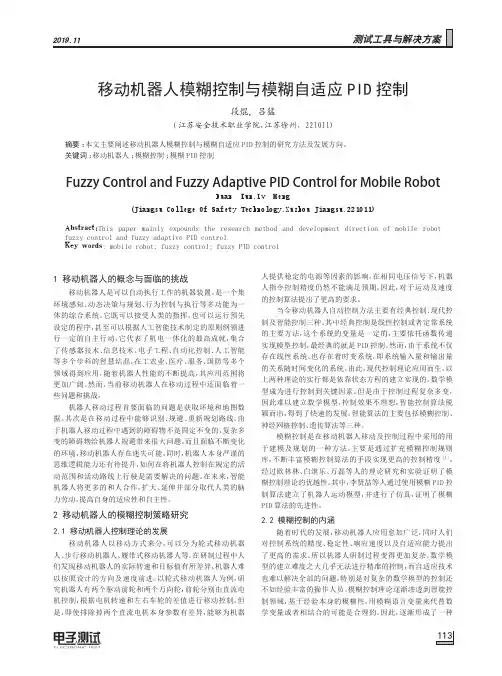
加入临时路径的移动机器人路径跟踪模糊控制孙涛;师五喜【摘要】A fuzzy control scheme of path tracking for mobile robots with uncertainty is presented. A temporary path is designed for the path tracking, which makes the robot move along the designed temporary path first, when it is near the desired path, the robot will go along it then. The whole tracking process is controlled by one fuzzy controller, which reduces the computation burden, and an integration term is added into the controller to eliminate the steady-state error. The performance of proposed approach is demonstrated through simulation and experiment examples.%对含不确定性的移动机器人系统设计了路径跟踪模糊控制方法。
该方法引入临时路径,使机器人先从初始位置出发沿临时路径行进,当移动到期望路径附近时,再让机器人跟踪期望路径。
整个控制过程只需要一个模糊控制器,极大地减少了工作量,并引进积分环节以消除稳态误差。
仿真和实验结果验证了该方法的有效性。
【期刊名称】《计算机工程与应用》【年(卷),期】2013(000)013【总页数】6页(P228-233)【关键词】临时路径;跟踪控制;模糊控制【作者】孙涛;师五喜【作者单位】天津工业大学电气工程与自动化学院,天津 300387;天津工业大学电气工程与自动化学院,天津 300387【正文语种】中文【中图分类】TP242.6近年来,许多学者对非完整移动机器人系统的跟踪控制问题进行了大量研究[1-6],根据参考轨迹是否为时间的函数,跟踪控制分为轨迹跟踪和路径跟踪。
XX设计(XX)外文资料翻译A Visual-Sensor Model for Mobile Robot Localisation Matthias Fichtner Axel Gro_mannArti_cial Intelligence InstituteDepartment of Computer ScienceTechnische Universit•at DresdenTechnical Report WV-03-03/CL-2003-02AbstractWe present a probabilistic sensor model for camera-pose estimation in hallways and cluttered o_ce environments. The model is based on the comparison of features obtained from a given 3D geometrical model of the environment with features present in the camera image. The techniques involved are simpler than state-of-the-art photogrammetric approaches. This allows the model to be used in probabilistic robot localisation methods. Moreover, it is very well suited for sensor fusion. The sensor model has been used with Monte-Carlo localisation to track the position of a mobile robot in a hallway navigation task. Empirical results are presented for this application.1 IntroductionThe problem of accurate localisation is fundamental to mobile robotics. To solve complex tasks successfully, an autonomous mobile robot has to estimate its current pose correctly and reliably. The choice of the localization method generally depends on the kind and number of sensors, the prior knowledge about the operating environment, and the computing resources available. Recently, vision-based navigation techniques have become increasingly popular [3]. Among the techniques for indoor robots, we can distinguish methods that were developed in the _eld of photogrammetry and computer vision, and methods that have their origin in AI robotics.An important technical contribution to the development of vision-based navigation techniques was the work by [10] on the recognition of 3D-objects from unknown viewpoints in single images using scale-invariant features. Later, this technique was extended to global localisation and simultaneous map building [11].The FINALE system [8] performed position tracking by using a geometrical model of the environment and a statistical model of uncertainty in the robot's pose given the commanded motion. The robot's position is represented by a Gaussian distribution and updated by Kalman _ltering. The search for corresponding features in camera image and world model is optimized by projecting the pose uncertainty into the camera image.Monte Carlo localisation (MCL) based on the condensation algorithm has been applied successfully to tour-guide robots [1]. This vision-based Bayesian _ltering technique uses a sampling-based density representation. In contrast to FINALE, it canrepresent multi-modal probability distributions. Given a visual map of the ceiling, it localises the robot globally using a scalar brightness measure. [4] presented avision-based MCL approach that combines visual distance features and visual landmarks in a RoboCup application. As their approach depends on arti_cial landmarks, it is not applicable in o_ce environments.The aim of our work is to develop a probabilistic sensor model for camerapose estimation. Given a 3D geometrical map of the environment, we want to find an approximate measure of the probability that the current camera image has been obtained at a certain place in the robot's operating environment. We use this sensor model with MCL to track the position of a mobile robot navigating in a hallway. Possibly, it can be used also for localization in cluttered o_ce environments and for shape-based object detection.On the one hand, we combine photogrammetric techniques for map-based feature projection with the exibility and robustness of MCL, such as the capability to deal with localisation ambiguities. On the other hand, the feature matching operation should be su_ciently fast to allow sensor fusion. In addition to the visual input, we want to use the distance readings obtained from sonars and laser to improve localisation accuracy.The paper is organised as follows. In Section 2, we discuss previous work. In Section 3, we describe the components of the visual sensor model. In Section 4, we present experimental results for position tracking using MCL. We conclude in Section 5.2 Related WorkIn classical approaches to model-based pose determination, we can distinguish two interrelated problems. The correspondence problem is concerned with _nding pairs of corresponding model and image features. Before this mapping takes place, the model features are generated from the world model using a given camera pose. Features are said to match if they are located close to each other. Whereas the pose problem consists of _nding the 3D camera coordinates with respect to the origin of the world model given the pairs of corresponding features [2]. Apparently, the one problem requires the other to be solved beforehand, which renders any solution to the coupled problem very di_cult [6].The classical solution to the problem above follows a hypothesise-and-test approach: (1)Given a camera pose estimate, groups of best matching feature pairs provideinitial guesses (hypotheses).(2)For each hypothesis, an estimate of the relative camera pose is computed byminimising a given error function de_ned over the associated feature pairs. (3)Now as there is a more accurate pose estimate available for each hypothesis, theremaining model features are projected onto the image using the associatedcamera pose. The quality of the match is evaluated using a suitable error function, yielding a ranking among all hypotheses.(4)The highest-ranking hypothesis is selected.Note that the correspondence problem is addressed by steps (1) and (3), and the poseproblem by (2) and (4).The performance of the algorithm will depend on the type of features used, e.g., edges, line segments, or colour, and the choice of the similarity measure between image and model, here referred to as error function. Line segments is the feature type of our choice as they can be detected comparatively reliably under changing illumination conditions. As world model, we use a wire-frame model of the operating environment, represented in VRML. The design of a suitable similarity measure is far more difficult.In principle, the error function is based on the di_erences in orientation between corresponding line segments in image and model, their distance and difference in length, in order of decreasing importance, in consideration of all feature pairs present. This has been established in the following three common measures [10]. e3D is defined by the sum of distances between model line endpoints and the corresponding plane given by camera origin and image line. This measure strongly depends on the distance to the camera due to back-projection. e2D;1, referred to as in_nite image lines, is the sum over the perpendicular distances of projected model line endpoints to corresponding, in_nitely extended lines in the image plane. The dual measure, e2D;2, referred to as in_nite model lines, is the sum over all distances of image line endpoints to corresponding, in_nitely extended model lines in the image plane.To restrict the search space in the matching step, [10] proposed to constrain the number of possible correspondences for a given pose estimate by combining line features into perceptual, quasi-invariant structures beforehand. Since these initial correspondences are evaluated by e2D;1 and e2D;2, high demands are imposed on the accuracy of the initial pose estimate and the image processing operations, includingthe removal of distortions and noise and the feature extraction. It is assumed to obtain all visible model lines at full length. [12, 9] demonstrated that a few outliers already can severely affect the initial correspondences in Lowe's original approach due to frequent truncation of lines caused by bad contrast, occlusion, or clutter.3 Sensor ModelOur approach was motivated by the question whether a solution to the correspondence problem can be avoided in the estimation of the camera pose. Instead, we propose to perform a relatively simple, direct matching of image and model features. We want to investigate the level of accuracy and robustness one can achieve this way.The processing steps involved in our approach are depicted in Figure 1. After removing the distortion from the camera image, we use the Canny operator to extract edges. This operator is relatively tolerant to changing illumination conditions. From the edges, line segments are identi_ed. Each line is represented as a single point (_; _) in the 2D Hough space given by _ = x cos _ + y sin _. The coordinates of the end points are neglected. In this representation, truncated or split lines will have similar coordinates in the Hough space. Likewise, the lines in the 3D map are projected onto the image plane using an estimate of the camera pose and taking into account the visibility constraints, and are represented as coordinates in the Hough space as well. We have designed several error functions to be used as similarity measure in the matching step. They are described in the following.Centred match count (CMC)The first similarity measure is based on the distance of line segments in the Hough space. We consider only those image features as possible matches that lie within a rectangular cell in the Hough space centred around the model feature. The matches are counted and the resulting sum is normalised. The mapping from the expectation (model features) to the measurement (image features) accounts for the fact that the measure should be invariant with respect to objects not modelled in the 3D map or unexpected changes in the operating environment. Invariance of the number of visible features is obtained by normalisation. Speci_cally, the centred match count measure sCMC is defined by:where the predicate p de_nes a valid match using the distance parameters (t_; t_) and the operator # counts the number of matches. Generally speaking, this similarity measure computes the proportion of expected model Hough points hei 2 He that are con_rmed by at least one measured image Hough point hmj 2 Hm falling within tolerance (t_; t_). Note that neither endpoint coordinates nor lengths are considered here.Grid length match (GLM)The second similarity measure is based on a comparison of the total length values of groupes of lines. Split lines in the image are grouped together using a uniform discretisation of the Hough space. This method is similar to the Hough transform for straight lines. The same is performed for line segments obtained from the 3D model. Let lmi;j be the sum of lengths of measured lines in the image falling into grid cell (i; j), likewise lei;j for expected lines according to the model, then the grid length match measure sGLM is de_ned as:For all grid cells containing model features, this measure computes the ratio of the total line length of measured and expected lines. Again, the mapping is directional, i.e., the model is used as reference, to obtain invariance of noise, clutter, and dynamic objects.Nearest neighbour and Hausdorf distanceIn addition, we experimented with two generic methods for the comparison of two sets of geometric entities: the nearest neighbour and the Hausdor_ distance. For details see [7]. Both rely on the de_nition of a distance function, which we based on the coordinates in the Hough space, i.e., the line parameter _ and _, and optionally the length, in a linear and exponential manner. See [5] for a complete description. Common error functionsFor comparisons, we also implemented the commonly used error functions e3D,e2D;1, and e2D;2. As they are de_ned in the Cartesian space, we represent lines in the Hessian notation, x sin _ y cos _ = d. Using the generic error function f, we de_ned the similarity measure as:where M is the set of measured lines and E is the set of expected lines. In case ofe2D;1, f is de_ned by the perpendicular distances between both model line endpoints, e1, e2, and the in_nitely extended image line m:Likewise, the dual similarity measure, using e2D;2, is based on the perpendicular distances between the image line endpoints and the in_nitely extended model line. Recalling that the error function e3D is proportional to the distances of model line endpoints to the view plane through an image line and the camera origin, we can instantiate Equation 1 using f3D(m; e) de_ned as:where ~nm denotes the normal vector of the view plane given by the image endpoints ~mi = [mx;my;w]T in camera coordinates.Obtaining probabilitiesIdeally, we want the similarity measure to return monotonically decreasing values as the pose estimate used for projecting the model features departs from the actual camera pose. As we aim at a generally valid yet simple visual-sensor model, the idea is to abstract from speci_c poses and environmental conditions by averaging over a large number of di_erent, independent situations. For commensurability, we want to express the model in terms of relative robot coordinates instead of absolute world coordinates. In other words, we assumeto hold, i.e., the probability for the measurement m, given the pose lm this image has been taken at, the pose estimate le, and the world model w, is equal to the probability of this measurement given a three-dimensional pose deviation 4l and the world model w.The probability returned by the visual-sensor model is obtained by simple scaling:4 Experimental ResultsWe have evaluated the proposed sensor model and similarity measures in a series of experiments. Starting with arti_cially created images using idealized conditions, we have then added distortions and noise to the tested images. Subsequently, we have used real images from the robot's camera obtained in a hallway. Finally, we have usedthe sensor model to track the position of the robot while it was travelling through the hallway. In all these cases, a three-dimensional visualisation of the model was obtained, which was then used to assess the solutions.Simulations using arti_cially created imagesAs a first kind of evaluation, we generated synthetic image features by generating a view at the model from a certain camera pose. Generally speaking, we duplicated the right-hand branch of Figure 1 onto the left-hand side. By introducing a pose deviation 4l, we can directly demonstrate its inuence on the similarity values. For visualisation purposes, the translational deviations 4x and 4y are combined into a single spatial deviation 4t. Initial experiments have shown only insigni_cant di_erences when they were considered independently.Fig. 2: Performance of CMC on arti_cially created images.For each similarity measure given above, at least 15 million random camera poses were coupled with a random pose deviation within the range of 4t < 440cm and 4_ < 90_ yielding a model pose.The results obtained for the CMC measure are depicted in Figure 2. The surface of the 3D plot was obtained using GNUPLOT's smoothing operator dgrid3d. We notice a unique, distinctive peak at zero deviation with monotonically decreasing similarity values as the error increases. Please note that this simple measure considers neither endpoint coordinates nor lengths of lines. Nevertheless, we obtain already a decent result.While the resulting curve for the GLM measure resembles that of CMC, the peak is considerably more distinctive. This conforms to our anticipation since taking the length of image and model lines into account is very signi_cant here. In contrast to the CMC measure, incidental false matches are penalised in this method, due to the differing lengths.The nearest neighbour measure turned out to be not of use. Although linear and exponential weighting schemes were tried, even taking the length of line segmentsinto account, no distinctive peak was obtained, which caused its exclusion from further considerations.The measure based on the Hausdor_ distance performed not as good as the first two, CMC and GLM, though it behaved in the desired manner. But its moderate performance does not pay off the longest computation time consumed among all presented measures and is subsequently disregarded.So far, we have shown how our own similarity measures perform. Next, we demonstrate how the commonly used error functions behave in this framework.The function e2D;1 performed very well in our setting. The resulting curve closely resembles that of the GLM measure. Both methods exhibit a unique, distinctive peak at the correct location of zero pose deviation. Note that the length of line segments has a direct e_ect on the similarity value returned by measure GLM, while this attribute implicitly contributes to the measure e2D;1, though both linearly. Surprisingly, the other two error functions e2D;2 and e3D performed poorly.Toward more realistic conditionsIn order to learn the e_ect of distorted and noisy image data on our sensor model, we conducted another set of experiments described here. To this end, we applied the following error model to all synthetically generated image features before they are matched against model features. Each original line is duplicated with a small probability (p = 0:2) and shifted in space. Any line longer than 30 pixel is split with probability p=0:3. A small distortion is applied to the parameters (_; _; l) of each line according to a random, zeromean Gaussian. Furthermore, features not present in the model and noise are simulated by adding random lines uniformly distributed in the image. Hereof, the orientation is drawn according to the current distribution of angles to yield fairly `typical' features.The results obtained in these simulations do not di_er significantly from the first set of experiments. While the maximum similarity value at zero deviation decreased, the shape and characteristics of all similarity measures still under consideration remained the same.Using real images from the hallwaySince the results obtained in the simulations above might be questionable with respect to real-world conditions, we conducted another set of experiments replacing the synthetic feature measurements by real camera images.To compare the results for various parameter settings, we gathered images with a Pioneer 2 robot in the hallway o_-line and recorded the line features. For two di_erent locations in the hallway exemplifying typical views, the three-dimensional space of the robot poses (x; y; _) was virtually discretized. After placing the robot manually at each vertex (x; y; 0), it performed a full turn on the spot stepwise recording images. This ensures a maximum accuracy of pose coordinates associated with each image. That way, more than 3200 images have been collected from 64 di_erent (x; y)locations. Similarly to the simulations above, pairs of poses (le; lm) were systematically chosenFig. 3: Performance of GLM on real images from the hallway.from with the range covered by the measurements. The values computed by the sensor model referring to the same discretized value of pose deviation 4l were averaged according to the assumption in Equation 2.The resulting visualisation of the similarity measure over spatial (x and y combined) and rotational deviations from the correct camera pose for the CMC measure exhibits a unique peak at approximately zero deviation. Of course, due to a much smaller number of data samples compared to the simulations using synthetic data, the shape of the curve is much more bumpy, but this is in accordance with our expectation.The result of employing the GLM measure in this setting is shown in Figure 3. As it reveals a more distinctive peak compared to the curve for the CMC measure, it demonstrates the increased discrimination between more and less similar feature maps when taking the lengths of lines into account.Monte Carlo Localisation using the visual-sensor modelRecalling that our aim is to devise a probabilistic sensor model for a camera mounted on a mobile robot, we continue with presenting the results for an application to mobile robot localisation.The generic interface of the sensor model allows it to be used in the correction step of Bayesian localisation methods, for example, the standard version of the Monte Carlolocalisation (MCL) algorithm. Since statistical independence among sensor readings renders one of the underlying assumptions of MCL, our hope is to gain improved accuracy and robustness using the camera instead of or in addition to commonly used distance sensors like sonars or laser.Fig. 4: Image and projected models during localisation.In the experiment, the mobile robot equipped with a _xed-mounted CCD camera had to follow a pre-programmed route in the shape of a double loop in the corridor. On its way, it had to stop at eight pre-de_ned positions, turn to a nearby corner or open view, take an image, turn back and proceed. Each image capture initiated the so-called correction step of MCL and the weights of all samples were recomputed according to the visual-sensor model, yielding the highest density of samples at the potentially correct pose coordinates in the following resampling step. In the prediction step, the whole sample set is shifted in space according to the robot's motion model and the current odometry sensor readings.Our preliminary results look very promising. During the position tracking experiments, i.e., the robot was given an estimate of its starting position, the best hypothesis for the robot's pose was approximately at the correct pose most of the time. In this experiment, we have used the CMC measure. In Figure 4, a typical camera view is shown while the the robots follows the requested path. The grey-level image depicts the visual input for feature extraction after distortion removal andpre-processing. Also the extracted line features are displayed. Furthermore, the world model is projected according to two poses, the odometry-tracked pose and the estimate computed by MCL which approximately corresponds to the correct pose, between which we observe translational and rotational error.The picture also shows that rotational error has a strong inuence on the degree ofcoincidental feature pairs. This effect corresponds to the results presented above, where the figures exhibit a much higher gradient along the axis of rotational deviation than along that of translational deviation. The finding can be explained by the effect of motion on features in the Hough space. Hence, the strength of our camera sensor model lays at detecting rotational disagreement. This property makes it especially suitable for two-wheel driven robots like our Pioneer bearing a much higher rotational odometry error than translational error.5 Conclusions and Future WorkWe have presented a probabilistic visual-sensor model for camera-pose estimation. Its generic design makes it suitable for sensor fusion with distance measurements perceived from other sensors. We have shown extensive simulations under ideal and realistic conditions and identified appropriate similarity measures. The application of the sensor model in a localisation task for a mobile robot met our anticipations. Within the paper we highlighted much scope for improvements.We are working on suitable techniques to quantitatively evaluate the performanceof the devised sensor model in a localisation algorithm for mobile robots. This will enable us to experiment with cluttered environments and dynamic objects. Combining the camera sensor model with distance sensor information using sensor fusion renders the next step toward robust navigation. Because the number of useful features varies significantly as the robots traverses an indoor environment, the idea to steer the camera toward richer views (active vision) offers a promising research path to robust navigation.References[1] F. Dellaert, W. Burgard, D. Fox, and S. Thrun. Using the condensationalgorithm for robust, vision-based mobile robot localisation. In Proc. of the IEEE Conf. on Computer Vision and Pattern Recognition, 1999.[2] D. DeMenthon, P. David, and H. Samet. SoftPOSIT: An algorithm forregistration of 3D models to noisy perspective images combining Softassign and POSIT. Technical report, University of Maryland, MD, 2001.[3] G. N. DeSouza and A. C. Kak. Vision for mobile robot navigation: A survey.IEEE Trans. on Pattern Analysis and Machine Intelligence, 24(2):237{267,2002.[4] S. Enderle, M. Ritter, D. Fox, S. Sablatn•og, G. Kraetzschmar, and G. Palm.Soccer-robot localisation using sporadic visual features. In IntelligentAutonomous Systems 6, pages 959{966. IOS, 2000.[5] M. Fichtner. A camera sensor model for sensor fusion. Master's thesis, Dept. ofComputer Science, TU Dresden, Germany, 2002.[6] S. A. Hutchinson, G. D. Hager, and P. I. Corke. A tutorial on visual servocontrol. IEEE Trans. on Robotics and Automation, 12(5):651{ 670, 1996.[7] D. P. Huttenlocher, G. A. Klanderman, and W. J. Rucklidge. Comparing imagesusing the Hausdor_ distance. IEEE Trans. on Pattern Analysis and MachineIntelligence, 15(9):850{863, 1993.[8] A. Kosaka and A. C. Kak. Fast vision-guided mobile robot navigation usingmodel-based reasoning and prediction of uncertainties. Com- puter Vision,Graphics, and Image Processing { Image Understanding, 56(3):271{329, 1992. [9] R. Kumar and A. R. Hanson. Robust methods for estimating pose and asensitivity analysis. Computer Vision, Graphics, and Image Processing { Image Understanding, 60(3):313{342, 1994.[10] D. G. Lowe. Three-dimensional object recognition from single twodimensionalimages. Arti_cial Intelligence, 31(3):355{395, 1987.[11] S. Se, D. G. Lowe, and J. Little. Vision-based mobile robot localization andmapping using scale-invariant features. In Proc. of the IEEE Int. Conf. onRobotics and Automation, pages 2051{2058, 2001.[12] G. D. Sullivan, L. Du, and K. D. Baker. Quantitative analysis of the viewpointconsistency constraint in model-based vision. In Proc. of the 4th Int. IEEE Conf.on Computer Vision, pages 632{639, 1993.13一个有关移动机器人定位的视觉传感器模型Matthias Fichtner Axel Gro_mannArti_cial Intelligence InstituteDepartment of Computer ScienceTechnische Universit•at DresdenTechnical Report WV-03-03/CL-2003-02摘要我们提出一个在走廊和传感器模型凌乱的奥西环境下的概率估计。
附件2:外文原文(复印件)Navigation and Control of a Wheeled Mobile RobotAbstract:Several approaches for incorporating navigation function approach into different controllers are developed in this paper for task execution by a nonholonomic system (e.g., a wheeled mobile robot) in the presence of known obstacles. The first approach is a path planning-based control with planning a desired path based on a 3-dimensional position and orientation information. A navigation-like function yields a path from an initial configuration inside the free configuration space of the mobile robot to a goal configuration. A differentiable, oscillator-based controller is then used to enable the mobile robot to follow the path and stop at the goal position. A second approach is developed for a navigation function that is constructed using 2-dimensional position information. A differentiable controller is proposed based on this navigation function that yields asymptotic convergence. Simulation results are provided to illustrate the performance of the second approach.1 IntroductionNumerous researchers have proposed algorithms to address the motion control problem associated with robotic task execution in an obstacle cluttered environment. A comprehensive summary of techniques that address the classic geometric problem of constructing a collision-free path and traditional path planning algorithms is provided in Section 9, .Literature Landmarks of Chapter 1 of [19]. Since the pioneering work by Khatib in [13], it is clear that the construction and use of potentialfunctions has continued to be one of the mainstream approaches to robotic task execution among known obstacles. In short, potential functions produce a repulsive potential field around the robot workspace boundary and obstacles and an attractive potential Þeld at the goal configuration. A comprehensive overview of research directed at potential functions is provided in [19]. One of criticisms of the potential function approach is that local minima can occur that can cause the robot to get stuck without reaching the goal position. Several researchers have proposed approaches to address the local minima issue (e.g., see [2],[3], [5], [14], [25]). One approach to address the local minima issue was provided by Koditschek in [16] for holonomic systems (see also [17] and [22]) that is based on a special kind of potential function, coined a navigation function, that has a refined mathematical structure which guarantees a unique minimum exists. By leveraging from previous results directed at classic (holonomic) systems, more recent research has focused on the development of potential function-based approaches for more challenging nonholonomic systems (e.g., wheeled mobile robots (WMRs)). For example, Laumond et al. [18] used a geometric path planner to generate a collision-free path that ignores the nonholonomic constraints of a WMR, and then divided the geometric path into smaller paths that satisfy the nonholonomic constraints, and then applied an optimization routine to reduce the path length. In [10] and [11], Guldner et al. use discontinuous, sliding mode controllers to force the position of a WMR to track the negative gradient of a potential function and to force the orientation to align with the negative gradient. In [1], [15], and [21], continuous potential field-based controllers are developed to also ensure position tracking of the negative gradient of a potential function, and orientation tracking of the negative gradient. More recently, Ge and Cui present a new repulsive potential function approach in [9] to address thecase when the goal is non-reachable with obstacles nearby (GNRON). In [23] and [24], Tanner et al. exploit the navigation function research of [22] along with a dipolar potential field concept to develop a navigation function-based controller for a nonholonomic mobile manipulator. Specifically, the results in [23] and [24] use a discontinuous controller to track the negative gradient of the navigation function, where a nonsmooth dipolar potential field causes the WMR to turn in place at the goal position to align with a desired orientation. In this paper, two different methods are proposed to achieve a navigation objective for a nonholonomic system. In the first approach, a 3-dimensional (3D) navigation-like function-based desired trajectory is generated that is proven to ultimately approach to the goal position and orientation that is a unique minimum over the WMR free configuration space. A continuous control structure is then utilized that enables the WMR to follow the path and stop at the goal position and orientation set point (i.e., the controller solves the unified tracking and regulation problem). The unique aspect of this approach is that the WMR reaches the goal position with a desired orientation and is not required to turn in place as in many of the previous results. As described in [4] and [20], factors such as the radial reduction phenomena, the ability to more effectively penalize the robot for leaving the desired contour, the ability to incorporate invariance to the task execution speed, and the improved ability to achieve task coordination and synchronization provide motivation to encapsulate the desired trajectory in terms of the current position and orientation. For the on-line 2D problem, a continuous controller is designed to navigate the WMR along the negative gradient of a navigation function to the goal position. As in many of the previous results, the orientation for the on-line 2D approach requires additional development (e.g., a separate regulation controller; a dipolar potential field approach [23], [24]; or a virtualobstacle [9]) to align the WMR with a desired orientation. Simulation results are provided to illustrate the performance of the second approach.2 Kinematic ModelThe class of nonholonomic systems considered in this paper can be modeled as a kinematic wheelwhere are defined asIn (1), the matrix is defined as followsand the velocity vector is defined aswith vc(t), ωc(t) ∈R denoting the linear and angular velocity of the system. In (2), xc(t), yc(t), and θ(t) ∈R denote the position and orientation, respectively, xc(t), yc(t) denote the Cartesian components of the linear velocity, and θ(t) ∈ R denotes the angular velocity.3 Control ObjectiveThe control objective in this paper is to navigate a non-holonomic system (e.g., a wheeled mobile robot) along a collision-free path to a constant,goal position and orientation, denoted by , in an obstacle cluttered environment with known obstacles. Specifically, the objective is to control the non-holonomic system along a path from an initial position and orientation to q∗∈D, where D denotes a free configuration space. The free configuration space D is a subset of thewhole configuration space with all configurations removed that involve a collision with an obstacle. To quantify the path planning-based control objective, the difference between the actual Cartesian position and orientation and the desired position and orientation, denotedby, is defined asas followswhere the desired trajectory is designed so that qd(t) → q∗. Motived by the navigation function approach in [16], a navigation-like function is utilized to generate the desired path qd(t). Specifically, the navigation-like function used in this paper is defined as follows Definition 1 Let D be a compact connected analytic manifold with boundary, and let q∗be a goal point in the interior of D. The navigation-like function ϕ(q): D →[0, 1], is a function satisfies the following properties:1. ϕ (q(t)) is first order and second order differentiable (i.e., and´exist on D).2. ϕ (q(t)) obtains its maximum value on the boundary of D.3. ϕ (q(t)) has unique global minimum at q (t) = q∗.4. If with εz, εr ∈ R being known positive constants.5. If ϕ(q(t)) is ultimately bounded by ε, then is ultimately bounded by εr with ε∈ R being some known positive constant.4 Online 3D Path Planner4.1 Trajectory PlanningThe 3D desired trajectory can be generated online as followswhere ϕ(q) ∈ R denotes a navigation-like function defined in Definition1, denotes the gradient vector of ϕ(q), and is anadditional control term to be designed. Assumption The navigation-like function defined in Definition 1 along with the desired trajectory generated by (6) ensures an auxiliary terms N (·) ∈ R3, defined assatisfy the following inequalitywhere the positive function ρ (·) is nondecreasing in and . The inequality given by (8) will be used in the subsequent stability analysis.4.2 Model TransformationTo achieve the control objective, a controller must be designed to track the desired trajectory developed in (6) and stop at the goal position q∗. To this end, the unified tracking and regulation controller presented in [7] can be used. To develop the controller in [7], the open-loop error system defined in (5) must be transformed into a suitable form. Specifically, the position and orientation tracking error signals defined in (5) are related to the auxiliary tracking error variables w(t) ∈R and through the following global invertible transformation [8]After taking the time derivative of (9) and using (1)-(5) and (9), the tracking error dynamics can be expressed in terms of the auxiliary variables defined in (9) as follows [8]where denotes a skew-symmetric matrix defined asand is defined asThe auxiliary control input introduced in (10)is defined in terms of and as follows4.3 Control DevelopmentTo facilitate the control development, an auxiliary error signal, denotedby, is defined as the difference between the subsequentlydesigned dynamic oscillator-like signal and the transformed variable z(t), defined in (9), as followsBased on the open-loop kinematic system given in (10) and the subsequent stability analysis, we design u(t) as follows [7]where k2 ∈ R is a positive, constant control gain. The auxiliary control term introduced in (15) is defined aswhere the auxiliary signal zd(t) is defined by the following differential equation and initial conditionThe auxiliary terms Ω1 (w, f, t) ∈ R and δd(t) ∈ R are defined asandrespectively, k1, α0, α1, ε1 ∈R are positive, constant control gains, and was defined in (12). As described in [8], motivation for the structure of (17) and (19) is based on the fact thatBased on (9), e (t) can be expressed in terms of,and zd (t) as followswhere are defined as followsMotivated by the subsequent stability analysis, the additional control term vr (t) in (6) is designed as followswhere k3, k4 ∈R denotes positive, constant control gains, and the positive functions ρ1 (zd1, z1, qd, e),ρ2 (zd1, z1, qd, e) ∈ R are defined as follows4.4 Closed-loop Error SystemAfter substituting (15) into (10), the dynamics for w(t) can be obtained as followswhere (14) and the properties of J in (11) were utilized. After substituting (16) into (26) for only the second occurrence of ua(t), utilizing (20) and the properties of J in (11), the final expression for the closed-loop error system for w(t) can be obtained as followsTo determine the closed-loop error system for, we take the timederivative of (14) and then substitute (10) and (17) into the resulting expression to obtain the following expressionAfter substituting (15) and (16) into (28), (28) can be rewritten as followsAfter substituting (18) into (29) for only the second occurrence of Ω1 (t) and then canceling common terms, the following expression can be obtainedSince the bracketed term in (30) is equal to ua (t) defined in (16), the final expression for the closed-loop error system for can be obtained asfollowsRemark 1 Based on the fact that δd (t) of (19) exponentially approachesan arbitrarily small constant, the potential singularities in (16), (17), and (18) are always avoided.4.5 Stability AnalysisTheorem 1 Provided qd (0) ∈ D, the desired trajectory generated by (6) along with the additional control term vr (t) designed in (24) ensures thatand.where εr is defined in Definition 1.Proof: Let V (t) ∈ R denote the following functionwhere k ∈R is a positive constant, V1 (t) ∈R denotes the following functionand V2 (qd) : D → R denotes a function as followsAfter taking the time derivative of (33) and then substituting (27) and (31) into the resulting expression and cancelling common terms, the following expression can be obtainedAfter taking the time derivative of (34) and utilizing (6), the following expression can be obtainedwhere N (·) is defined in (7). Based on (8), úV2 (t) can be upper bounded as followsAfter substituting (21) into (37), the following inequality can be obtainedwhere the vector is defined as followsand the positive function ρ1 (zd1, z1, qd, e) andρ2 (zd1, z1, qd, e) are defined in (25). After substituting (24) into (38), V2 (t) can be rewritten as followsBased on (35) and (40), the time derivative of V (t) in (32) can be upper bounded by the following inequalitywhere the positive constant are defined as followsCase 1: If , from the Property 4 in Definition 1, it is clearthatCase 2: If , it is clear from (32), (33), (34), and (41) thatwhere and are positive constants. Based on (42), V (t) can be upper bounded as followsthereforeBased on (32), (34), and (44), it is clear thatIf qd (0) is not on the boundary of D, ϕ(qd (0)) < 1. Then k can be adjusted to ensureBased on (45) and (46), ϕ (qd (t)) < 1, hence qd (t) ∈ D from Definition1. It is clearly from (43) that ϕ (qd) is ultimately bounded by²z. Therefore, if, k4 can be adjusted to ensure, whereε is defined in Definition 1. Hence by the Property 5 in Definition 1,is ultimately bounded by εr.¤Theorem 2 The kinematic control law given in (15)-(19) ensures global uniformly ultimately bounded (GUUB) position and orientation tracking in the sense thatwhere ε1 was given in (19), , and ε3and γ0 are positive constants. Proof: Based on (33) and (35), V1 (t) of (35) can be upper bounded as followsBased on (48), the following inequality can be obtainedBased on (33), (49) can be rewritten as followswhere the vector Ψ1 (t) is de fined in (39). From (33) and (49), it is clear that w (t) ,∈L∞. Based on (19) and (20), we can conclude that zd (t)∈ L∞. From (14) and, zd (t) ∈ L∞, it is clear that z (t) ∈ L∞. Since w(t), z (t) ∈ L∞, based on the inverse transformation from (9), e (t) ∈L∞. Based on qd (t) ∈ L∞ from Theorem 1 and e (t) ∈ L∞, it is clear that q (t) ∈ L∞. From (22)-(25), qd (t), zd (t), z (t), e (t) ∈ L∞, and the properties in Definition 1, we can conclude that vr (t), qd (t) ∈ L∞. Based on (12) and q (t), z (t), qd (t) ∈ L∞, f (θ, z2, qd) ∈ L∞. Then Ω1 (t) ∈ L∞ from(18). Then u (t), ua (t), zd (t) ∈ L∞ from (15)-(17). Based on the fact thatf (θ, z2, qd), z (t), u (t) ∈ L∞, then (10) can be used to conclude w (t), z (t) ∈ L∞. It is clear from z(t) , zd (t) ∈ L∞ that∈ L∞. Then standard signal chasing arguments can be employed to conclude that all of the remaining signals in the control and the system remain bounded during closed-loop operation.Based on (19), (20), (39), and (50), the triangle inequality can be applied to (14) to prove thatUtilizing (50)-(51), the result given in (47) can be obtained from taking the inverse of the transformation given in (9). ¤Remark 2 Although qd (t) is a collision-free path, the stability result in Theorem 2 only ensures practical tracking of the path in the sense that the actual WMR trajectory is only guaranteed to remain in a neighborhood of the desired path. From (5) and (47), the following bound can bedevelopedwhere qd (t) ∈ D based on the proof for Theorem 1. To ensure that q (t) ∈ D, the free configuration space needs to be reduced to incorporate the effects of the second and third terms on the right hand side of (52). To this end, the size of the obstacles could be increased by, where ε3ε1 can be made arbitrarily small by adjusting the control gains. To minimize the effects of ε2, the initial conditions w (0) and z (0) (and hence, could be required to be sufficiently small enough to yield a feasible path to the goal.5 Online 2D NavigationIn the previous approach, the size of the obstacles is required to be increased due to the fact that the navigation-like function is formulated in terms of the desired trajectory. In the following approach, the navigation function proposed in [22] is formulated based on current position feedback, and hence, q (t) can be proven to be a member of D without placing restrictions on the initial conditions.5.1 Trajectory PlanningLet ϕ(xc, yc) ∈R denote a 2D position-based navigation function defined in D that is generated online, where the gradient vector of ϕ(xc, yc) is defined as followsLet θd (xc, yc) ∈R denote a desired orientation that is defined as a function of the negated gradient of the 2D navigation function as followswhere arctan 2 (·) : R2 → R denotes the four quadrant inverse tangent function [26], where θd (t) is confined to the followingregion As stated in [21], by defining, then θd(t) remains continuous alongany approaching direction to the goal position. See Appendix for an expression for θd(t) based on the previous continuous definition for θd(t). Remark 3 As discussed in [22], the construction of the function ϕ(q(t)), coined a navigation function, that satisfies the first three properties in Definition 1 for a general obstacle avoidance problem is nontrivial. Indeed, for a typical obstacle avoidance, it does not seem possible toconstruct ϕ(q(t)) such that only at q (t) = q∗. That is, as discussed in [22], the appearance of interior saddle points (i.e., unstable equilibria) seems to be unavoidable; however, these unstable equilibria do not really cause any difficulty in practice. That is, ϕ(q(t)) can be constructed as shown in [22] such that only a .few. initial conditions will actually get stuck on the unstable equilibria. 5.2 Control Development Based on the open-loop system introduced in (1)-(4) and the subsequent stability analysis, the linear velocity control input vc (t) is designed as followswhere kv ∈R denotes a positive, constant control gain, and was introduced in (5). After substituting (55) into (1), the following closed-loop system can be obtainedThe open-loop orientation tracking error system can be obtained bytaking the time derivative of in (5) as followswhere (1) was utilized. Based on (57), the angular velocity control inputωc (t) is designed as followswhere kω ∈ R denotes a positive, constant control gain, and θd(t) denotes the time derivative of the desired orientation. See Appendix for an explicit expression forθd (t). After substituting (58) into (57), the closed-loop orientation tracking error system is given by the following linear relationshipLinear analysis techniques can be used to solve (59) as followsAfter substituting (60) into (56) the following closed-loop error system can be determined5.3 Stability AnalysisTheorem 3 The control input designed in (55) and (58) along with the navigation function ensure asymptotic navigation in the sense thatProof: Let: D → R denote the following non-negative functionAfter taking the time derivative of (63) and utilizing (1), (53), and (56), the following expression can be obtainedBased on the development provided in Appendix, the gradient of thenavigation function can be expressed as followsAfter substituting (65) into (64), the following expression can be obtainedAfter utilizing a trigonometric identity, (66) can be rewritten as followswhere g(t) ∈ R denotes the following positive functionBased on (53) and the property of the navigation function (Similar to theProperty 1 of Definition 1), it is clear that on D; hence, (55) can be used to conclude that vc (t) ∈ L∞ on D. Development is also provided in the Appendix that proves θd (t) ∈ L∞ on D; hence, (58) can be used to show that ωc (t) ∈ L∞ on D. Based on the fact that vc (t) ∈L∞ on D, (1)-(4) can be used to prove that xc (t), yc (t) ∈ L∞ on D. After taking the time derivative of (53) the following expression can be obtainedSince xc (t), yc (t) ∈L∞ on D, and since each element of the Hessian matrix in (69) is bounded by the property of the navigation function (Similar to the Property 1 ofDefinition 1), it is clear that gú(t) ∈ L∞ on D. Based on (63), (67), (68), and the fact that g(t) ∈ L∞ on D, then Lemma A.6 of [6] can be invoked to prove thatin the region D. Based on the fact that 1 from (60), then (70)can be used to prove that. Therefore the result in (62) can be obtained based on the analysis in Remark 3. ¤Remark 4 The control development in this section is based on a 2D position navigation function. To achieve the objective, a desired orientation θd (t) was defined as a function of the negated gradient of the 2D navigation function. The previous development can be used to provethe result in (62). If a navigation function can be found suchthat, then asymptotic navigation can be achieved by the controller in (55) and (58); otherwise, a standard regulation controller (e.g., see [8] for several candidates) could be implemented to regulate theorientation of the WMR from. Alternatively, a dipolar potential field approach [23], [24] or a virtual obstacle [9] could be utilized to align the gradient field of the navigation function to the goal orientation of the WMR.6 Simulation ResultsTo illustrate the performance of the controller given in (55) and (58), a numerical simulation was performed to navigate the WMR fromto.Since the properties of a navigation function are invariant under a diffeomorphism, a diffeomorphism is developed to map the WMR free configuration space to a model space [17]. Specifically, a positive function was chosen as followswhere κ is positive integer parameter, and the boundary functionand the obstacle function are defined as followsIn (72), and are the centers of the boundary and the obstacle respectively, r0, r1 ∈R are the radii of the boundary and the obstacle respectively. From (71) and (72), it is clear that the model space is a unit circle that excludes a circle described by the obstaclefunction. If more obstacles are present, the corresponding obstacle functions can be easily incorporated into the navigation function [17]. In [17], Koditschek proved that in (71) is the navigationfunction for, provided that κ is big enough. For the simulation, the model space configuration is selected as followswhere the initial and goal configuration were selected asThe control inputs defined in (55) and (58) were utilized to drive the WMR to the goal point along the negated gradient angle. The control gains kv and kω were adjusted to the following values to yield the best performanceOnce the WMR reached the goal position, the regulation controller in [8]was implemented to regulate the WMR from . The actual trajectory of WMR is shown in Figure 1. The outer circle in Figure1 depicts the outer boundary of the obstacle free space and the inner circle represents the boundary around an obstacle. The resulting position and orientation errors for the WMR are depicted in Figure 2, where therotational error shown in Figure 2 is the error between the actual orientation and goal orientation. The control in-put velocities vc(t) and ωc(t) defined in (55) and (58), respectively, are depicted in Figure 3. Note that the angular velocity input was artificially saturated between ±90[deg ·s−1].7 ConclusionsTwo approaches are developed to incorporate navigation function approach into different controllers for task execution by a WMR in the presence of known obstacles. The first approach utilizes a navigation-like function that is based on 3D position and orientation information. The navigation-like function yields a path from an initial configuration inside the free configuration space to a goal configuration. A differentiable, oscillator-based controller is then used to enable the mobile robot to follow the path and stop at the goal position. Using this approach, a WMR was proven to yield uniformly ultimately bounded path following and regulation to the goal point with an arbitrarily defined goal orientation (i.e., the WMR is not required to spin in place at the goal position to achieve a desired orientation). A second approach is developed that uses a navigation function that is constructed using 2D position information. A differentiable controller is proposed based on this navigation function. The advantage of this approach is that it yieldsasymptotic position convergence; however, the WMR cannot stop at an arbitrary orientation without additional development. Simulation results are provided to illustrate the performance of the second approach. AppendixBased on the definition of θd (t) in (54), θd (t) can be expressed in terms of the natural logarithm as follows [26]where . After exploiting the following identities [26]and then utilizing (74) the following expressions can be obtainedAfter utilizing (75) and (76), the following expression can be obtainedBased on the expression in (74), the time derivative of θd (t) can be written as followswhere·After substituting (1), (79), and (80) into (78), the following expression can be obtainedAfter substituting (55) and (77) into (81), the following expression can be obtained¸.By part 1 of Definition 1, each element of the Hessian matrix is bounded;hence, from (82), it is straightforward that。
机器人外文翻译(中英文翻译)机器人外文翻译(中英文翻译)With the rapid development of technology, the use of robots has become increasingly prevalent in various industries. Robots are now commonly employed to perform tasks that are dangerous, repetitive, or require a high level of precision. However, in order for robots to effectively communicate with humans and fulfill their intended functions, accurate translation between different languages is crucial. In this article, we will explore the importance of machine translation in enabling robots to perform translation tasks, as well as discuss current advancements and challenges in this field.1. IntroductionMachine translation refers to the use of computer algorithms to automatically translate text or speech from one language to another. The ultimate goal of machine translation is to produce translations that are as accurate and natural as those generated by human translators. In the context of robots, machine translation plays a vital role in allowing them to understand and respond to human commands, as well as facilitating communication between robots of different origins.2. Advancements in Machine TranslationThe field of machine translation has experienced significant advancements in recent years, thanks to breakthroughs in artificial intelligence and deep learning. These advancements have led to the development of neural machine translation (NMT) systems, which have greatly improved translation quality. NMT models operate by analyzinglarge amounts of bilingual data, allowing them to learn the syntactic and semantic structures of different languages. As a result, NMT systems are capable of providing more accurate translations compared to traditional rule-based or statistical machine translation approaches.3. Challenges in Machine Translation for RobotsAlthough the advancements in machine translation have greatly improved translation quality, there are still challenges that need to be addressed when applying machine translation to robots. One prominent challenge is the variability of language use, including slang, idioms, and cultural references. These nuances can pose difficulties for machine translation systems, as they often require a deep understanding of the context and cultural background. Researchers are currently working on developing techniques to enhance the ability of machine translation systems to handle such linguistic variations.Another challenge is the real-time requirement of translation in a robotic setting. Robots often need to process and translate information on the fly, and any delay in translation can affect the overall performance and efficiency of the robot. Optimizing translation speed without sacrificing translation quality is an ongoing challenge for researchers in the field.4. Applications of Robot TranslationThe ability for robots to translate languages opens up a wide range of applications in various industries. One application is in the field of customer service, where robots can assist customers in multiple languages, providing support and information. Another application is in healthcare settings, where robots can act as interpreters between healthcare professionals and patientswho may speak different languages. Moreover, in international business and diplomacy, robots equipped with translation capabilities can bridge language barriers and facilitate effective communication between parties.5. ConclusionIn conclusion, machine translation plays a crucial role in enabling robots to effectively communicate with humans and fulfill their intended functions. The advancements in neural machine translation have greatly improved translation quality, but challenges such as language variability and real-time translation requirements still exist. With continuous research and innovation, the future of machine translation for robots holds great potential in various industries, revolutionizing the way we communicate and interact with technology.。
模糊神经网络外文翻译文献(文档含中英文对照即英文原文和中文翻译)原文:Neuro-fuzzy generalized predictive control ofboiler steam temperatureXiangjie LIU, Jizhen LIU, Ping GUANABSTRACTPower plants are nonlinear and uncertain complex systems. Reliablecontrol of superheated steam temperature is necessary to ensure high efficiency and high load-following capability in the operation of modern power plant. A nonlinear generalized predictive controller based on neuro-fuzzy network (NFGPC) is proposed in this paper. The proposed nonlinear controller is applied to control the superheated steam temperature of a 200MW power plant. From the experiments on the plant and the simulation of the plant, much better performance than the traditional controller is obtained.Keywords:Neuro-fuzzy networks; Generalized predictive control; Superheated steam temperature1. IntroductionContinuous process in power plant and power station are complex systems characterized by nonlinearity, uncertainty and load disturbance. The superheater is an important part of the steam generation process in the boiler-turbine system, where steam is superheated before entering the turbine that drives the generator. Controlling superheated steam temperature is not only technically challenging, but also economically important.From Fig.1,the steam generated from the boiler drum passes through the low-temperature superheater before it enters the radiant-type platen superheater. Water is sprayed onto the steam to control the superheated steam temperature in both the low and high temperature superheaters. Proper control of the superheated steam temperature is extremely important to ensure theoverall efficiency and safety of the power plant. It is undesirable that the steam temperature is too high, as it can damage the superheater and the high pressure turbine, or too low, as it will lower the efficiency of the power plant. It is also important to reduce the temperature fluctuations inside the superheater, as it helps to minimize mechanical stress that causes micro-cracks in the unit, in order to prolong the life of the unit and to reduce maintenance costs. As the GPC is derived by minimizing these fluctuations, it is amongst the controllers that are most suitable for achieving this goal.The multivariable multi-step adaptive regulator has been applied to control the superheated steam temperature in a 150 t/h boiler, and generalized predictive control was proposed to control the steam temperature. A nonlinear long-range predictive controller based on neural networks is developed into control the main steam temperature and pressure, and the reheated steam temperature at several operating levels. The control of the main steam pressure and temperature based on a nonlinear model that consists of nonlinear static constants and linear dynamics is presented in that.Fig.1 The boiler and superheater steam generation processFuzzy logic is capable of incorporating human experiences via the fuzzy rules. Nevertheless, the design of fuzzy logic controllers is somehow time consuming, as the fuzzy rules are often obtained by trials and errors. In contrast, neural networks not only have the ability to approximate non-linear functions with arbitrary accuracy, they can also be trained from experimental data. The neuro-fuzzy networks developed recently have the advantages of model transparency of fuzzy logic and learning capability of neural networks. The NFN is have been used to develop self-tuning control, and is therefore a useful tool for developing nonlinear predictive control. Since NFN is can be considered as a network that consists of several local re-gions, each of which contains a local linear model, nonlinear predictive control based on NFN can be devised with the network incorporating all the local generalized predictive controllers (GPC) designed using the respective local linear models. Following this approach, the nonlinear generalized predictive controllers based on the NFN, or simply, the neuro-fuzzy generalized predictive controllers (NFG-PCs)are derived here. The proposed controller is then applied to control the superheated steam temperature of the 200MW power unit. Experimental data obtained from the plant are used to train the NFN model, and from which local GPC that form part of the NFGPC is then designed. The proposed controller is tested first on the simulation of the process, before applying it to control the power plant.2. Neuro-fuzzy network modellingConsider the following general single-input single-output nonlinear dynamic system:),1(),...,(),(),...,1([)(''+-----=u y n d t u d t u n t y t y f t y∆+--/)()](),...,1('t e n t e t e e (1)where f[.]is a smooth nonlinear function such that a Taylor series expansion exists, e(t)is a zero mean white noise and Δis the differencing operator,''',,e u y n n n and d are respectively the known orders and time delay ofthe system. Let the local linear model of the nonlinear system (1) at the operating point )(t o be given by the following Controlled Auto-Regressive Integrated Moving Average (CARIMA) model:)()()()()()(111t e z C t u z B z t y z A d ----+∆= (2) Where)()(),()(1111----∆=z andC z B z A z A are polynomials in 1-z , the backward shift operator. Note that the coefficients of these polynomials are a function of the operating point )(t o .The nonlinear system (1) is partitioned into several operating regions, such that each region can be approximated by a local linear model. Since NFN is a class of associative memory networks with knowledge stored locally, they can be applied to model this class of nonlinear systems. A schematic diagram of the NFN is shown in Fig.2.B-spline functions are used as the membership functions in the NFN for the following reasons. First,B-spline functions can be readily specified by the order of the basis function and the number of inner knots. Second, they are defined on a bounded support, andthe output of the basis function is always positive, i.e.,],[,0)(j k j j k x x λλμ-∉=and ],[,0)(j k j j k x x λλμ-∈>.Third, the basis functions form a partition of unity, i.e.,.][,1)(min,∑∈≡jmam j k x x x x μ (3)And fourth, the output of the basis functions can be obtained by a recurrence equation.Fig. 2 neuro-fuzzy network The membership functions of the fuzzy variables derived from the fuzzy rules can be obtained by the tensor product of the univariate basis functions. As an example, consider the NFN shown in Fig.2, which consists of the following fuzzy rules:IF operating condition i (1x is positive small, ... , and n x is negative large),THEN the output is given by the local CARIMA model i:...)()(ˆ...)1(ˆ)(ˆ01+-∆+-++-=d t u b n t y a t y a t y i i a i in i i i a )(...)()(c i in i b i in n t e c t e n d t u b cb -+++--∆+ (4)or)()()()()(ˆ)(111t e z C t u z B z t yz A i i i i d i i ----+∆= (5) Where )()(),(111---z andC z B z A i i i are polynomials in the backward shift operator 1-z , and d is the dead time of the plant,)(t u i is the control, and )(t e i isa zero mean independent random variable with a variance of 2δ. Themultivariate basis function )(k i x a is obtained by the tensor products of the univariate basis functions,p i x A a nk k i k i ,...,2,1,)(1==∏=μ(6)where n is the dimension of the input vector x, and p, the total number of weights in the NFN, is given by,∏=+=nk i i k R p 1)((7)Where i k and i R are the order of the basis function and the number of inner knots respectively. The properties of the univariate B-spline basis functions described previously also apply to the multivariate basis function, which is defined on the hyper-rectangles. The output of the NFN is,∑∑∑=====p i i i p i ip i i i a y aa y y 111ˆˆˆ (8)译文:锅炉蒸汽温度模糊神经网络的广义预测控制Xiangjie LIU, Jizhen LIU, Ping GUAN摘要发电厂是非线性和不确定性的复杂系统。
Autonomous robot obstacle avoidance using a fuzzy logic control schemeWilliam MartinSubmitted on December 4, 2009CS311 - Final Project1. INTRODUCTIONOne of the considerable hurdles to overcome, when trying to describe areal-world control scheme with first-order logic, is the strong ambiguity found in both semantics and evaluations. Although one option is to utilize probability theory in order to come up with a more realistic model, this still relies on obtaining information about an agent's environment with some amount of precision. However, fuzzy logic allows an agent to exploit inexactness in its collected data by allowing for a level of tolerance. This can be especially important when high precision or accuracy in a measurement is quite costly. For example, ultrasonic and infrared range sensors allow for fast and cost effective distance measurements with varying uncertainty. The proposed applications for fuzzy logic range from controlling robotic hands with six degrees of freedom1 to filtering noise from a digital signal.2 Due to its easy implementation, fuzzy logic control has been popular for industrial applications when advanced differential equations become either computationally expensive or offer no known solution. This project is an attempt to take advantage of these fuzzy logic simplifications in order to implement simple obstacle avoidance for a mobile robot. 2. PHYSICAL ROBOT IMPLEMENTATION2.1. Chassis and sensorsThe robotic vehicle's chassis was constructed from an Excalibur EI-MSD2003 remote control toy tank. The device was stripped of all electronics, gears, and extraneous parts in order to work with just the empty case and two DC motors for the tank treads. However, this left a somewhat uneven surface to work on, so high-density polyethylene (HDPE) rods were used to fill in empty spaces. Since HDPE has a rather low surface energy, which is not ideal for bonding with other materials, a propane torch was used to raise surface temperature and improve bonding with an epoxy adhesive.Three Sharp GP2D12 infrared sensors, which have a range of 10 to 80 cm, were used for distance measurements. In order to mount these appropriately, a 2.5 by 15 cm piece of aluminum was bent into three even pieces at 135 degree angles. This allows for the IR sensors to take three different measurements at 45 degree angles (right, middle, and left distances). This sensor mount was then attached to an HDPE rod with mounting tape and the rod was glued to the tank base with epoxy. Since the minimum distance that can be reliably measured with these sensors is 10 cm, the sensors were placed about 9 cm from the front of the vehicle. This allowed measurements to be taken very close to the front of the robot.2.2. ElectronicsIn order to control the speed of each motor, pulse-width modulation (PWM) was usedto drive two L2722 op amps in open loop mode (Fig. 1). The high input resistance of these ICs allow for the motors to be powered with very little power draw from the PWM circuitry. In order to isolate the motor's power supply from the rest of the electronics, a 9.6 V NiCad battery was used separately from a standard 9 V that demand on the op amps led to a small amount of overheating during continuous operation. This was remedied by adding small heat sinks and a fan to the forcibly disperse heat.Fig. 1. The control circuit used for driving each DC motor. Note that the PWM signal was between 0 and 5 V.2.3. MicrocontrollerComputation was handled by an Arduino Duemilanove board with anATmega328 microcontroller. The board has low power requirements and modifications. In addition, it has a large number of prototyping of the control circuit and based on the Wiring language. This board provided an easy and low-cost platform to build the robot around.3. FUZZY CONTROL SCHEME FORIn order to apply fuzzy logic to the robot to interpret measured distances. While the final algorithm depended critically on the geometry of the robot itself and how it operates, some basic guidelines were followed. Similar research projects provided both simulation results and ideas for implementing fuzzy control.3,4,53.1. Membership functionsThree sets of membership functions were created to express degrees of membership for distances, translational speeds, and rotational speeds. This made for a total of two input membership functions and eight output membership functions (Fig.2). Triangle and trapezoidal functions were used exclusively since they are quick to compute and easy to modify. Keeping computation time to a minimum was essential so that many sets of data could be analyzed every second (approximately one every 40 milliseconds). The distance membership functions allowed the distances from the IR sensors to be quickly "fuzzified," while the eight speed membership functions converted fuzzy values back into crisp values.3.2.Rule baseOnce the input data was fuzzified, the eight defined fuzzy logic rules (Table I) were executed in order to assign fuzzy values for translational speed and rotation. This resulted in multiple values for the each of the fuzzy output components. It was then necessary to take the maximum of these values as the fuzzy value for each component. Finally, these fuzzy output values were "defuzzified" using themax-product technique and the result was used to update each of the motor speeds.(a)(b)(c)Fig. 2. The membership functions used for (a) distance, (b) translation speed, and (c) rotational speed. These functions were adapted from similar work done in reference 3.4. RESULTSThe fuzzy control scheme allowed for the robot to quickly respond to obstacles it could detect in its environment. This allowed it to follow walls and bend around corners decently without hitting any obstacles. However, since the IR sensors' measurements depended on the geometry of surrounding objects, there were times when the robot could not detect obstacles. For example, when the IR beam hit asurface with oblique incidence, it would reflect away from the sensor and not register as an object. In addition, the limited number of rules used may have limited the dynamics of the robot's responses. Some articles suggest as many as forty rules6 should be used, while others tend to present between ten and twenty. Since this project did not explore complex kinematics or computational simulations of the robot, it is difficult to determineexactly how many rules should be used. However, for the purposes of testing fuzzy logic as a navigational aide, the eight rules were sufficient. Despite the many problems that IR and similar ultrasonic sensors have with reliably obtaining distances, the robustness of fuzzy logic was frequently able to prevent the robot from running into obstacles.5. CONCLUSIONThere are several easy improvements that could be made to future iterations of this project in order to improve the robot's performance. The most dramatic would be to implement the IR or ultrasonic sensors on a servo so that they could each scan a full 180 degrees. However, this type of overhaul may undermine some of fuzzy logic's helpful simplicity. Another helpful tactic would be to use a few types of sensors so that data could be taken at multiple ranges. The IR sensors used in this experiment had a minimum distance of 10 cm, so anything in front of this could not be reliably detected. Similarly, the sensors had a maximum distance of 80 cm so it was difficult to react to objects far away. Ultrasonic sensors do offer significantly increased ranges at a slightly increased cost and response time. Lastly, defining more membership functions could help improve the rule base by creating more fine tuned responses. However, this would again increase the complexity of the system.Thus, this project has successfully implemented a simple fuzzy control scheme for adjusting the heading and speed of a mobile robot. While it is difficult to determine whether this is a worthwhile application without heavily researching other methods, it is quite apparent that fuzzy logic affords a certain level of simplicity in the design of a system. Furthermore, it is a novel approach to dealing with high levels of uncertainty in real-world environments.6. REFERENCES1 Ed. M. Jamshidi, N. Vadiee, and T. Ross, Fuzzy logic and control: software and hardware applications, (Prentice Hall: Englewood Cliffs, NJ) 292-328.2 Ibid, 232-261.3 W. L. Xu, S. K. Tso, and Y. H. Fung, "Fuzzy reactive control of a mobile robot incorporating a real/virtual target switching strategy," Robotics and Autonomous Systems, 23(3), 171-186 (1998).4 V. Peri and D. Simon, “Fuzzy logic control for an autonomous robot,” 2005 Annual Meeting of the North American Fuzzy Information Processing Society, 337-342 (2005).5 A. Martinez, E. Tunstel, and M. Jamshidi, "Fuzzy-logic based collision-avoidance for a mobile robot," Robotica, 12(6) 521–527 (1994).6 W. L. Xu, S. K. Tso, and Y. H. Fung, "Fuzzy reactive control of a mobile robot incorporating a real/virtual target switching strategy," Robotics and AutonomousSystems, 23(3), 171-186 (1998).采用模糊逻辑控制使自主机器人避障设计威廉马丁提交于2009年12月4日CS311 -最终项目1 引言其中一个很大的障碍需要克服,当试图用控制逻辑一阶来描述一个真实世界设计在发现在这两个语义评价中是个强大的模糊区。
摘 要:提出了一种基于模糊控制的移动机器人路径控制的设计思路,并给出了以ATmage128单片机为核心的控制系统硬件设计方案。
系统预先设定目标,移动机器人根据超声波传感器感知周围环境,采用模糊控制进行路径规划,从而进行机器人自主移动到达目标。
论文给出了模糊控制隶属度函数,介绍了模糊控制规则。
同时介绍了显示电路、超声波测距电路、电机驱动电路、无线通信电路等硬件模块接口电路。
关键词:路径规划;ATmega128;模糊控制;L298N;nRF903Abstract: This paper explains a design of fuzzy controller for mobile path planning and the project of the hardware of the system based on Atmega128 MCU. This system could set the route in advance. The mobile robot could know the environment with the help of ultrasonic sensor, and arrive the goal through the fuzzy control for mobile robot path planning. The membership function of fuzzy control is given. The rule of fuzzy control is stated. The interface of LCD, the interface of ultrasonic sensor, the interface of motor drive and the interface of wireless communication is discussed.Key works: Path planning ; A Tmega128 ; Fuzzy control ; L298N ; nRF903中图分类号:TP242 文献标识码:B 文章编号:1001-9227(2009)01-0025-040 引 言智能移动机器人是一类能够通过传感器感知环境和自身状态,实现在有障碍物的环境中向目标的自主运动,从而完成一定作业功能的机器人系统[1]。
外文文献原稿和译文原稿IntroductionIn the modern industrial control field, along with the rapid development of computer technology, the emergence of a new trend of intelligent control, namely to machine simulation human thinking mode, using reasoning, deduce and induction, so the means, the production control, this is artificial intelligence. One expert system, fuzzy logic and neural network is the artificial intelligence of several key research hot spot. Relative to the expert system, the fuzzy logic belongs to the category of computational mathematics and contain the genetic algorithm, the chaos theory and linear theory etc, it comprehensive of operators practice experience, has the design is simple and easy to use, strong anti-interference ability and reaction speed, easy to control and adaptive ability, etc. In recent years, in a process control, built to touch, estimation, identify, diagnosis, the stock market forecast, agricultural production and military sciences to a wide range of applications. To carry out in-depth research and application of fuzzy control technology, the paper introduces the basic theory of fuzzy control technology and development, and to some in the application of the power electronics are introduced.Fuzzy Logic and Fuzzy Control1, fuzzy logic and fuzzy control conceptIn 1965, the university of California, Berkeley, computer experts Lofty Zadeh put forward "fuzzy logic" concept, the root lies in the area's logic or clear logic distribution, used to define the confused, unable to quantify or the problem of precision, for ˙ in a man's von based on "true-false" reasoning mechanism, and thus create a electronic circuit and integrated circuit of the Boolean algorithm, fuzzy logic to fill the gaps in special things in sampling and analysis of blank. On the basis of fuzzy logic fuzzy set theory, a particular things as the set of features membership, he can be in "is" and "no" within the scope of the take between any value. And fuzzy logic is reasonable quantitative mathematical theory, the mathematical basis forfundamental for is to deal with these the statistical uncertain imprecise information.Fuzzy control based on fuzzy logic is a process of description of the control algorithm. For parameters precisely known mathematical model, we can use Berd graph or chart to analysts the Nyquist process to obtain the accurate design parameters. And for some complex system, such as particle reaction, meteorological forecast equipment, establishing a reasonable and accurate mathematical model is very difficult, and for power transmission speed of vector control problems, although it can be measured by the model that, but for many variables and nonlinear variation, the accurate control is very difficult. And fuzzy control technology only on the basis of the practical experience and the operator and intuitive inference, also relies on design personnel and research and development personnel of experience and knowledge accumulation, it does not need to establish equipment model, so basically is adaptive, and have strong robustness. After many years development, there have been many successful application of the fuzzy control theory of the case, such as Rutherford, Carter and Ostergaard were applied and metallurgical furnace and heat exchangers control device.2, the analysis method is discussedIndustrial control stability of the system is discussed the premise of the problem, because of the nonlinear and not to the unity of the description, make a judgment, so the fuzzy control system analysis method of stability analysis has been a hot spot, comprehensive in recent years you of scholars paper published the system stability analysis has these several circumstances :1), LiPuYa panov method: direct method based on the discrete time (D-T) and continuous time fuzzy control stability analysis and design method, the stability condition of the relative comparison conservative.2), sliding variable structure system analysis method3), round stability criterion methods: use sector bounded nonlinear concept, according to the stability criterion, led to the stability of the fuzzy control.4), POPOV criterion5), other methods such as relationship matrix analysis, exceed stable theory, phase-plane, matrix inequality or convex optimization method, fuzzy hole-holemapping etc, detailed information and relevant literature many, in this one no longer etc.Set Design of Fuzzy ControlThe design of the fuzzy control is a very complicated process, in general, take the design steps and tools is more normative. The fuzzy controller general use of the special software and hardware, universal hardware chip in on the market at present is more, including main products are shown below. And special IC has developed very fast, it special IC and software controller integrates in together.In the process of design, the design of the general to take steps for:1, considering whether the subject by fuzzy control system. That is considered the routine control mode of may.2, from equipment operation personnel place to get as much information.3 and selecting the mathematical model could, if use the conventional method design, estimate the equipment performance characteristics.4, determine the fuzzy logic control object.5, determine the input and output variables.6, determine the variables as determined the belonging of the range.7, confirm the variables of the corresponding rules.8, determine the scale coefficients.9, if have a ready-made, mathematical model of fuzzy controller with already certain of system simulation, observation equipment performance, and constantly adjust rules and scale coefficients until reaching satisfaction performance. Or to design fuzzy controller.10, real-time operation controller, constantly adjust to the best performance. Fuzzy Control Application and ProspectAs artificial intelligence of a new research field, the fuzzy control absorb lessons from the traditional design method and other new technology's essence, in many fields has made considerable progress. In the new type of power electronic and automatic control system, some experts in the linear adding the conditions of the power amplifier, the application of the fuzzy control based on the servo motor control, in the fuzzy control system with the PID and model reference adaptive control (MRAC)comparison proved the advantages of the method of fuzzy control. Fuzzy turn sent gain tuned controller views of the induction motor drive system vector control Fuzzy control as a is the development of new technology, now in most experts also to focus on application system research, and make considerable achievement, but in the theory research and system analysis or relative backward, so much so that some scholars have questioned its theoretical basis and effective. In view of this can be clear that the fuzzy control the combination of theory and practice is still needs to be further explored. The development prospects are very attractive, and in recent years, its theoretical study also made significant progress. In the past forty years of the development process, the fuzzy control also has some limitations: 1) control precision low, performance is not high, stability is poorer; 2) theory system is not complete. 3) the adaptive ability low. For these weaknesses, the fuzzy control and some other new technology, such as neural network (NN), genetic algorithm, and the combination of to a higher level of application development expand the huge space.SummaryFuzzy control as a comprehensive application example, in the global information the push of wave, in the next few decades, to the rapid development of economy will inject new vitality, the expert thinks, the next generation of industrial control is the basis of fuzzy control and neural network, and chaos theory as the pillar of the artificial intelligence. With the fuzzy control theory research and further more perfect of, the scope of application of the growing and supporting the development and manufacture of IC, the fuzzy control will be open to the field of industrial automation development of light application prospect, but also to the various areas of the researchers suggest more important task.译文引言在现代工业控制领域,伴随着计算机技术的突飞猛进,出现了智能控制的新趋势,即以机器模拟人类思维模式,采用推理、演绎和归纳等手段,进行生产控制,这就是人工智能。
本科毕业设计(论文)中英文对照翻译(此文档为word格式,下载后您可任意修改编辑!)原文The investigation of an autonomous intelligent mobile robot systemfor indoor environment navigationS KarelinAbstractThe autonomous mobile robotics system designed and implemented for indoor environment navigation is a nonholonomic differential drive system with two driving wheels mounted on the same axis driven by two PID controlled motors and two caster wheels mounted in the front andback respectively. It is furnished with multiple kinds of sensors such as IR detectors ,ultrasonic sensors ,laser line generators and cameras,constituting a perceiving system for exploring its surroundings. Its computation source is a simultaneously running system composed of multiprocessor with multitask and multiprocessing programming. Hybrid control architecture is employed on the rmbile robot to perform complex tasks. The mobile robot system is implemented at the Center for Intelligent Design , Automation and Manufacturfing of City University of Hong Kong.Key words:mobile robot ; intelligent control ; sensors ; navigation IntroductionWith increasing interest in application of autonomous mobile robots in the factory and in service environments,many investigations have been done in areas such as design,sensing,control and navigation,etc. Autonomousreaction to the real wand,exploring the environment,follownng the planned path wnthout collisions and carrying out desired tasks are the main requirements of intelligent mobile robots. As humans,we can conduct these actions easily. For robots however,it is tremendously difficult. An autonomous mobile robot should make use of various sensors to sense the environment and interpret and organize the sensed information to plan a safe motion path using some appropriate algorithms while executing its tasks. Many different kinds of senors havebeen utilized on mobile robots,such as range sensors,light sensors,force sensors,sound sensors,shaft encoders,gyro scope s,for obstacle awidance,localizatio n,rmtion sensing,navigation and internal rmnitoring respectively. Many people use infrared and ultrasonic range sensors to detect obstacles in its reaching ser range finders are also employed in obstacle awidance behavior of mobile robots in cluttered space.Cameras are often introduced into the vision system for mobile robot navigation. Although many kinds of sensors are available,sensing doesn’t mean perceiving. The mechanical shape and driving type are commonly first taken into consideration while implementing a rmbile robot. A robot’s shape can have a strong impact on how robust it is,and DC serve rmtors or stepOper motors are often the two choices to employ as actuators. The shape of a robot may affect its configurations of components,ae sthetics,and even the movement behaviors of the robot. An improper shape can make robot run a greater risk of being trapped in a cluttered room or of failing to find its way through a narrow space. We choose an octahedral shape that has both advantages of rectangular and circular shapes,and overcomes their drawbacks. The framework of the octahedral shaped robot is easy to make,components inside are easily arrange and can pass through narrow places and rotate wrath corners and nearby objects,and is more aesthetic in appearance. The perception subsystem accomplishes the task of getting various data from thesurroundings,including distance of the robot from obstacles,landmarks,etc.Infrared and ultrasonic range sen}rs,laser rangefinders and cameras are utilized and mounted on the rmbile robot to achieve perception of the environment. These sensors are controlled independently by some synchronously running microprocessors that are arranged wrath distributive manner,and activated by the main processor on which a supervising program runs. At present,infrared and ultranic sensors,laser rangefinders are programmed to detect obstacles and measure distance of the robot from objects in the environment,and cameras are programmed for the purpose of localization and navigation.The decision-making subsystem is the most important part of an intelligent mobile robot that organizes and utilizes the information obtained from the perception subsystem. It obtains reasonable results by some intelligent control algorithm and guides the rmbile robot. On our mobile robotic system intelligence is realized based on behaviourism and classical planning principles. The decision-making system is composed of twa levels global task planning based on knowledge base and map of working enviro nment,reactive control to deal with the dynamic real world. Reaction tasks in the decision-making system are decomposed into classes of behaviors that the robot exhibits to accomplish the task. Fuzzy logic is used to implement some basic behaviors. A state machine mechanism is applied to coordinate different behaviors. Because manykinds of electronic components such as range sensors,cameras,frame grabbers,laser line generators,microprocessors,DC motors,encoders,are employed on the mobile robot,a power source must supply various voltage levels which should are stable and have sufficient power. As the most common solution to power source of mobile robots,two sealed lead acid batteries in series writh 24 V output are employed in our mobile robot for the rmtor drive components and electronic components which require 24 V,15V,士12V,+9V,士5V,variously. For the conversion and regulation of the voltage,swritching DC DC converters are used because of their high efficiency,low output ripple and noise,and wride input voltage range. Three main processors are Motorola MC68040 based single board computers on which some supervisory programs and decision-making programs run. These MC68040 boards run in parallel and share memory using a VMEbus. Three motorola MC68HC11 based controllers act as the lower level controllers of the infrared and ultranic range senors,which communicate with the main processors through serial ports. The multi-processor system is organized into a hierarchical and distributive structure to implement fast gathering of information and rapid reaction. Harmony,a multiprocessing and multitasking operating system for real-time control,runs on the main processors to implement multiprocessing and multitasking programming. Harmony is a runtime only environment and program executions are performed by downloadingcrosscompiled executable images into target processors. The hardware architecture of the mobile robot is shown in Fig. Robots control For robots,the three rmst comrmn drive systems are wheels,tracks and legs. Wheeled robots are mechanically simpler and easier to construct than legged and tracked systems that generally require more complex and heavier hardware,so our mobile robot is designed as a wheeled robot. For a wheeled robot,appropriate arrangements of driving and steering wheels should be chosen from differential,synchro,tricycle,and automotive type drive mechanisms. Differential drives use twa caster wheels and two driven wheels on a common axis driven independently,which enable the robot to move straight,in an arc and turn in place. All wheels are rotate simultaneously in the synchro drive;tricycle drive includes two driven wheels and one steering wheel;automobile type drive rotates the front twa wheels together like a car. It is obvious that differential drive is the simplest locomotion system for both programming and construction.However,a difficult problem for differentially driven robots is how to make the robot go straight,especially when the motors of the two wheels encounter different loads. To follow a desired path,the rmtor velocity must be controlled dynamically. In our mobile robot system a semv motor controller is used which implements PID control.Ibwer amplifiers that drive the motors amplify the signals from each channel of serwcontroller. Feedback is provided by shaft encoders on the wheels.The block diagram of the motor control electronic components are shown in Fig. 2,and the strategy of two wheel speed control based PID principle is illustrated in Fig.3. Top loop is for tracking the desired left motor velocity;bottom loop for tracking right motor velocity;Integral loop ensures the robot to go straight as desired and controls the steering of the robot. This is a simple PI control that can satisfy the general requirements.Sensing subsystemSensor based planning makes use of sensor information reflecting the current state of the environment,in contrast to classical planning,which assumes full knowledge of the environment prior to planning. The perceptive subsystem integrates the visual and proximity senors for the reaction of the robot. It plays an important role in the robot behavioral decision-making processes and motion control. Field of view of perceptive subsystem is the first consideration in the design of the sensing system. Fneld of view should be wide enough with sufficient depth of field to understand well the robot’s surroundings. Multiple sensors can provide information that is difficult to extract from single sensor systems. Multiple sensors are complementary to each other,providing a better understanding of the work environment. Omnidirectional sensory capability is endowed on our mobile robot. When attempting to utilize multiple senors,it must be decided how many different kinds of sensorsare to be used in order to achieve the desired motion task,both accurately and economically.Ultrasonic range sensing is an attractive sensing rmdalityfor mobile robots because it is relatively simple to implement and process,has low cost and energy consumption. In addition,high frequencies can be used to minimize interference from the surrounding environment. A special purpose built infrared ranging system operates similar to sonar,determining the obstacle’s presence or absence and also the distance to an object. For detecting smaller obstacles a laser rangefinder can be used. It can be titled down to the ground to detect the small objects near the robot. Identifying robot self position and orientation is a basic behavior that can be part of high level complex behaviors. For localizing a dead reckoning method is adopted using the output of shaft encoders. This method can have accumulated error on the position and orientation. Many external sensors can be used for identification of position and orientation. Cameras are the most popular sensor for this purpose,because of naturally occurring features of a mom as landmarks,such as air conditioning system,fluorescent lamps,and suspended ceiling frames.Any type of sensor has inherent disadvantages that need to be taken into consideration. For infrared range senors,if there is a sharply defined boundary on the target betweendifferent materials,colors,etc.,the sensor may not be able to calculate distance accurately. Some of these problemscan be avoided if due care is taken when installing and setting up the sensor. Crosstalk and specular reflection are the two main problems for ultrasonic sensors. The firing rates,blanking intervals,firing order,and timeouts of the ultrasonic sensor system can configured to improve performance. Laser ranging systems can fail to detect objects made of transparent materials or with poor light reflectivity. In this work,we have chosen range sensors and imaging sensors as the primary source of information. The range sensors employed include ultrasonic sensors and short and long range infrared sensors with features above mentioned. The imaging sensors comprise gray scale video cameras and laser rangefinders. Twenty-four ultrasonic sensors are arranged in a ring with a separation angle of 15 degrees on our mobile robot to detect the objects in a 3600 field of view. This will allow the robot to navigatearound an unstructured environment and to construct ac curate sonar maps by using environmental objects as naturally occurring beacons. With the sonar system we can detect objects from a minimum range of 15 cm to a maximum range of 10. 0 m. Infrared range sensors use triangulation,emitting an infrared spot from an emitter,and measuring the position of the imaged spot with a PSD (position sensitive detector).Since these devices use triangulation,object color,orientation,and ambient light have greater effect on sensitivity rather than accuracy. Since the transmission signal is light instead of sound,we may expect a dramatically shortercycle time for obtaining all infrared sensor measurements. A getup of 16 short and a group of 16 long infrared sensors are mounted in twa rings with equal angular Generally speaking,the robot motion closed control loops comprising sensing,planning,and acting should take very short cycle times,so a parallel computation mechanism is employed in our mobile robot based on multiprocessor. Usually we can make events run in parallel on single microprocessor or multiprocessor by twa methods,multitasking and multiprocessing. Well known multitasking OS is like Microsoft window' 95 and UNIX OS that can make multitask run in parallel on a sequential machine by giving a fraction of time to each behavior looply. In fact,multitask mechanism just simulates the effect of all events running simultaneously. Running all events on multiprocessor can realize true parallelism. In our mobile robot,using Harmony OS both multitasking and multiprocessing programming is implemented on multiprocessor (MC68040 processors) which share memories and communicate each other by VMEbus. Harmony allows creating many tasks as desired which can be map toseveral microprocesors and run in parallel .In addition,tasks written in C run on MC68040 can activate the assembly code in the MC68HC11 SBC which control infrared and ultrasonic sensors and get distances dates. These SBC run simultaneously with MC68040 processors. An instance of an implemented task structure is shown in Fng. 5.Some experiments,such as following lines,avoiding obstacles and area filling have been carried out on the rmbile system to demonstrates its real-time reactions to the working surroundings and robustness of the system. ConclusionWe have described the implementation of a intelligent mobile robot testbed for autonomous navigation in indoor environments and for investigation of relative theories and technologies of intelligent systems. The robot is furnished with range sensors,laser line generators and vision system to perceive its surroundings. Parallel computation based on multiprocessor is employed in the mobile robot to improve its power of reasoning and response. Low level processing and sensor control is carried out with low cost dedicated microcontrollers. A task based real-time operating system supports a variety of different control structures,allowing us to experiment with different approaches. The experiments indicate the effectiveness of the mobile robot system .The platform has been used for experimenu and research such as sensor data fusion,area filling,feedback control,as well as artificial intelligence.译文基于室内环境导航的智能自动移动机器人系统研究卡若琳摘要这种为室内境导航条件下设计生产的自主移动机器人系统是一个不完整的差速传动系统,它有两个安装在同一轴上通过两个PID控制的电机驱动的驱动轮和两个分别安装在前部和后部的脚轮。
附录:The robot1.The role of robots”The role of robots Is a high-level integration of control theory, robotics, machinery and electronics, computers, materials and bionic product. In industry, medicine, agriculture, construction and even the military have important applications in such areas. Now, the international concept of robots has been gradually approaching the same. In general, people can accept the claim that the robot is controlled by its own power and ability to achieve the various functions of a machine. The United Nations Organization for Standardization adopted by the American Federation of Robotics to the robot under the definition: "a programmable and versatile, used to move materials, parts, tools, operating machines; or to perform different tasks have to change and Programmable action specialized systems.2.Evaluation criteriaCapacity of evaluation criteria Robot capability evaluation criteria include: intelligence, refers to feelings and perceptions, including memory, calculation, comparison, identification, judging, decision-making, learning and logical reasoning, etc.; function, refers to flexibility, versatility or space occupied, etc.; physics can be means the power, speed, continuous operation capability, reliability, combined with nature, life and so on. Therefore, it can be said robot is a biological function of three-dimensional coordinates of the machine.position of the robotThe composition of the robot Robots in general by the executing agency, drives, detection devices and control system, etc.. Implementing agency, the robot body, the buttocks generally use the space for open-chain linkages, the movement of which the Deputy (rotate or move the Deputy Vice-) often referred to as joints, and joints shall be the number of robots are usually a fewdegrees of freedom. According to joint configuration types and the different forms of movement coordinates, the robot implementing agencies can be divided into rectangular type, cylindrical coordinate type, polar coordinate type and other types of joint coordinate type. For anthropomorphic considerations, often the relevant parts of the robot body are known as the base, waist, arm, wrist, hand (gripper or end effector) and the Ministry of walking (for mobile robot), etc. . Drive device is driven by movement of the body implementing agencies, in accordance with the directives issued by the signal control system, by means of dynamic components, the robot action is needed. It is the input signal, the output is the line, the amount of angular displacement. Drive robot is mainly used in electric drives, such as stepper motors, servo motors, etc. In addition, there is also hydraulic, pneumatic, etc. drives.Detecting device is the role of real-time detection robot's movement and work of the required feedback to the control system, compared with the configuration information, the right to adjust the implementing agencies to ensure the robot's movements to meet the intended requirements. As a sensor detecting device can be divided into two categories: one is internal information sensors for detecting the internal situation in various parts of robots, such as the joint position, velocity, acceleration, etc., and the measured information as a feedback the signal sent to the controller, to form a closed-loop control. The other is external information sensors, used to obtain information about the operation of robots and other objects and external environment of information, so that the robot moves to adapt to changing circumstances, so that to achieve a higher level of automation, even the machine person has a certain "feel" to the intelligent development, such as visual, sound and other external sensors sense given object of work,information about the working environment, the use of such information constitutes a major feedback loop, which will greatly enhance the work of the robot accuracy. Control system in two ways. One is the centralized control, that is, the robot's control by a microcomputer to complete. The other is decentralized (level)-type control, which uses multiple computers to share the control of robots, such as when using the upper and lower two computers together to complete the robot control, the host often used for system management, communication, kinematics and dynamics calculations, to send commands to the lower-level computer information; as a junior from the machine, the joints corresponding to a CPU, for interpolation and servo control processing operations to achieve a given movement, to the host feedback. According to the different operational mission requirements, the robot control mode can be divided into point to point control, continuous path control and force (torque) control.4.History of RobotsRobot History 1920 Czechoslovakia writer Karel Capek in his • sci-fi novel "Rossum's Universal Robots company", according to Robota (Czech, intended to "labor, slave labor") and Robotnik (Polish, the original intent as "workers"), to create a "robot" is the word. World Expo 1939 in New York on display at the Westinghouse Electric Company manufactured home robot Elektro. It is controlled by a cable, you can walk, say 77 words, or even smoke, but still far from the real chores. But it give people a vision of domestic robots to become more specific. Asimov sci-fi masters 1942, the United States put forward the "Three Laws of Robotics." Although this is only the creation of science fiction, but later became the principle of academic research and development by default. • In 1948 Norbert Weiner published in "control theory" to explain the machine in the communication and control function and the nervous, sensory function of the common law, first proposed as the core of computer-automated factory. 1954, American George • Dwyer created the world's first programmable robot and registered patents. This mechanical hand in accordance with different programs in different jobs, so has the versatility and flexibility. 1956 Dartmouth meeting • Marvin Minsky has made his views on intelligent machines: Smart Machine "to create an abstract model of the surrounding environment, if you encounter problems, from abstract model to find a solution" . This definition affects the subsequent 30 years of intelligent robot research direction. Dwyer and the United States in1959, inventor Joseph • Ingeborg joined hands to create the first industrial robot. Subsequently, the establishment of the world's first a robot manufacturing plant - Unimation company. As Ingeborg R & D for industrial robots and publicity, he was known as the "father of industrial robots." AMF Inc. in 1962, the United States produced "VERSTRAN" (meaning universal handling), and Unimation produced Unimate as a truly commercial industrial robots, and exported to countries around the world, setting off a worldwide study of robots and robot the globe. 1962 -1,963 years the application of sensors to improve the operability of the robot. People try all kinds of sensors installed on the robot, including the 1961 Ernst used in tactile sensors, Tomovic and Boni 1962, the world's first "smart hand" on the use of pressure sensors, while the McCarthy in 1963, has begun to add visual sensor in robot system, and in 1965, helped MIT launched the world's first with a vision sensor that can identify and locate building blocks of the robotic system. 1965 Johns Hopkins University Applied Physics Laboratory • developed Beast robot. Beast has been through sonar systems, photoelectric tubes and other devices, the environmental correction own position. 60 mid-20th century, the U.S. Massachusetts Institute of Technology, Stanford University, University of Edinburgh, been set up in the robot lab. The United States with the rise of the second-generation sensors research, "there feel" of the robot, artificial intelligence and to work towards it. The world's first intelligent robot Shakey Stanford Research Institute in 1968, the United States announced that they successfully developed a robot Shakey. It is with a vision sensor, according to the instructions of people to discover and crawl the building blocks of a computer to control it, but there is a room so much. Shakey can be regarded as the world's first intelligent robot, beginning the prelude to the third generation of robot research and development. 1969, Ichiro Kato, Waseda University Laboratory developed the first robot to walk, walk. Ichiro Kato, the long-term commitment to research humanoid robot, known as "the father of humanoid robot." Japanese experts has been to develop humanoid robots and robot technology, known for entertainment, then go one step further hastened the development of Honda's ASIMO and Sony's QRIO. In 1973 the world's first robot and small computers to work together, they gave birth to the U.S. company Cincinnati Milacron robot T3. Unimation introduced in 1978, the U.S. general industrial robot PUMA, which marks the industrial robot technology has reached full maturity. PUMA is still work in the factory in the forefront. 1984 Ingeborg pushed robot Helpmate, the robot can deliver mealsto patients in the hospital and get drugs, to send e-mail. In the same year, he predicted: "I want robots to clean the floor, cooking, washing out to help me to check security." In 1998 Denmark introduced Lego Robot (Mind-storms) package, so get with the building-block robot manufacturing the same, relatively simple and can arbitrarily assembled, the robot started to enter the private world. In 1999 Sony introduced Aibo robot dog (AIBO), immediately sold out, and from entertainment robots become the robot forward one of the ways ordinary family. In 2002 the U.S. introduced the iRobot robotic vacuum cleaner Roomba, it can avoid obstacles, automatic design of the road route, but also in the power is insufficient, automatically towards charging seat. Roomba is the world's largest-selling and most commercial household robots. an authorized agent iRobot Corporation Beijing: Beijing Science and Technology Co., Ltd. Micro-Mesh, Tomohiro http / / net cn. In June 2006, Microsoft launched the Microsoft Robotics Studio, robotics modular, unified platform, it became increasingly evident, Bill • Gates predicted that household robots will soon be sweeping the world5.Robot category articlesBeing born in science fiction, like, people are full of fantasy robot. Perhaps it is because the definition of fuzzy robots, which gave the people full of imagination and creative space. Domestic robots: to help people take care of life, to do simple household chores. Manipulator-type robot: Can automatic, repeatable programming, multi-functional, there are several degrees of freedom can be fixed or movement, for associated automation systems. Programmable Robot: According to the order and conditions of apre-requirement in turn control the robot's mechanical movements.Teaching-playback robot: Adoption of the guidance or other means, the first robot moves the church, enter the work process, the robot will automatically repeat operations. NC robots: do not have to move the robot through the values, language, etc. for teaching the robot, the robot according to the information after teaching job. Feel-controlled robot: the use of sensors to obtain information on control of robot action. Adaptive control robot: able to adapt to changes in the environment, control their own actions. Learning control for robots: can "understand" the work experience, with a certain degree of learning function, and the "learning" experience for the work. Intelligent Robots: The artificial intelligence robot to determine its actions. China's environment, starting from the application of robotics experts, robotsare divided into two categories, namely industrial robots and special robot. The so-called industrial robots for industrial areas of multi-joint or multi-DOF robot manipulators. In addition to the special robot is outside of industrial robots used for non-manufacturing and the service of mankind advanced robots, including: service robots, underwater robots, entertainment robots, military robots, agricultural robots, robot-based machinery. In the special robots, some branches have developed rapidly, there is a separate system for trends, such as service robots, underwater robots, military robots,micro-operation of robots. At present, the international robot scholars, starting from the application environment, the robot is also divided into two categories: manufacturing environment of industrial robots and the non-manufacturing environment, the service and humanoid robots, This classification is consistent with our The. Also known as unmanned aerial robot machines, in recent years, the family in the military robotics, unmanned aerial vehicles are the most active research activities, technological progress, the largest research and procurement of funds into the largest and most experienced in the field of combat. 80 years, the world is basically the development of unmanned aerial vehicles based on the main line of the United States to move forward, regardless of the technical level, the types and number of UAVs, the U.S. ranking first in the world.6.Robot varieties articles6.1 Unmanned aircraftdrones "Detachment" Unmanned Aerial Vehicle Throughout the history of UAV development can be said that modern warfare is to promote the UAV development. The impact of modern warfare UAV is also growing. The first and during World War II, despite the emergence and use of unmanned aerial vehicles, but because of low levels of technology, unmanned aerial vehicles does not play a significant role. The Korean War in the United States use of unmanned reconnaissance and attack aircraft, but in limited quantities. In the ensuing war in Vietnam, the Middle East war, UAVs have become an essential weapon systems. In the Gulf War, the war in Bosnia and Kosovo war, has become the main reconnaissance UAV types. French "Red Hawk" unmanned aerial vehicle U.S. Air Force suffered heavy losses during the Vietnam War, was shot down aircraft, 2500, killed more than 5,000 pilots, the U.S. domestic public outcry. To this end the Air Force increased use of theUAV. Such as "buffalo hunters" UAV mission over North Vietnam 2500 times, low altitude photographs, injury rate of only 4%. AQM-34Q-type 147 firebee UAV Flight 500 several times, to conduct electronic eavesdropping, radio interference, dispersal of metal chaff and for some people to open up access, and so the aircraft. High-altitude unmanned reconnaissance aircraft In the 1982 war in the Bekaa Valley, Israeli forces discovered through aerial reconnaissance. Syria in the Bekaa Valley, a large concentration of troops. June 9, the Israeli army deployed US-made E-2C "Hawkeye" early warning surveillance aircraft to Syrian forces, and sent every day, "Scout" and "vicious dog" and unmanned aerial vehicles more than 70 sorties against Syrian forces in air defense positions Airport repeated reconnaissance, and to send images taken early warning aircraft and ground command. In this way, the Israeli army and accurately identify the location of the radar of the Syrian forces, and then launch the "wolf" type of anti-radar missiles, destroying the Syrian forces a lot of radar, missiles and automatic antiaircraft guns, and forced Syrian forces did not dare turn the radar, in order to in order to Army was the target to create the conditions for the aircraft. Phantom UAV The outbreak of the Gulf War in 1991, the U.S. military first face the problem of the Sand Sea is to be found in the vast hidden Iraqi Scud missile launchers. If someone reconnaissance aircraft, it must be round-trip flights over the desert, long exposure to the Iraqi army antiaircraft fire, under extremely dangerous. To this end, the U.S. military unmanned aerial surveillance has become the main force. Throughout the Gulf War, "Pioneer," the U.S. military to use unmanned aerial vehicles UAVs most kinds of U.S. forces deployed in the Gulf region a total of six Pioneer unmanned aerial vehicles with a total of 522 sorties flown, flight time of up to 1640 hours . At that time, regardless of day or night, every day there is always a Pioneer UAV flying over the Gulf. In order to destroy the Iraqi forces in the coastal fortifications built by strong, February 4 USS Missouri Chengye reaching offshore area, Pioneer UAV taking off from its deck, using infrared detectors were shot and send the images of ground targets to the command center. A few minutes later, warships and 406 mm guns began to bombard targets, unmanned aerial vehicles for the gun to school constantly firing. USS Wisconsin took over after the Missouri, so bombarded for three days straight, so that Iraqi artillery positions, radar network, command and communications center was completely destroyed. During the Gulf War, taking off only from the two battleships there is a pioneer in UAV 151 sorties, flying more than 530 hoursto complete the target search, battlefield warning, maritime interdiction and naval gunfire support missions. Brevel UAV During the Gulf War, the Pioneer unmanned aerial vehicles have become pioneers of the U.S. Army troops. It is for the Army's 7th Army for aerial reconnaissance, shooting a large number of Iraqi tanks, command centers and missile launch position of the image, and send it to the helicopter unit, followed by the U.S. military sent the "Apache" attack helicopters of the targets attack, if necessary, can call for artillery fire support units. Pioneer aircraft survivability strong in the 319 sorties were flown, only one was hit, there are 4 ~ 5 due to electromagnetic interference and distress. In addition to the U.S., the United Kingdom, France, Canada also deployed unmanned aerial vehicles. Such as France's "fawn" division is equipped with a "Malte" UAV row. When the French troops fighting in Iraqin-depth, first sending the enemy reconnaissance unmanned aerial vehicles, according to detected conditions, the French escaped the Iraqi army tanks and artillery positions. 1995 Bosnian war, because troops need, "Predator" unmanned aerial vehicles will soon be transported to the front. Serb forces in the NATO air strikes of the supply lines, ammunition depots, command center, the "Predator" has played an important role. It first carried out reconnaissance and found that target to guide the aircraft to attack someone, and then for the war effort. It also provided for the United Nations peacekeeping force in Bosnia and Herzegovina on the main road military vehicles movement, and to determine whether the parties complied with the peace agreement. U.S. military and thus the "Predator," called the "battle of the low-altitude satellites." In fact, satellites can only provide instant images on the battlefield, while the UAV could be a long time hovering over the battlefield to stay on the battlefield and thus able to provide continuous real-time image, unmanned aerial vehicles is also much cheaper than using satellites. March 24, 1999, the US-led NATO banner of "safeguarding human rights" under the guise of the Federal Republic of Yugoslavia began bombing the outbreak of that shocked the world, "the Kosovo war." In the 78 days of bombing, NATO deployed a total of 32 million per aircraft, ships into more than 40 vessels, dropped bombs, 13 million tons, resulted in an unprecedented catastrophe in Europe since World War II. Federal Republic of Yugoslavia is mountainous and forest terrain, as well as more than rainy days more than the climatic conditions significantly affected the NATO reconnaissance satellites andhigh-altitude reconnaissance plane effect, the Sierra Leone Army also brings a fierce anti-aircraft fire, it was not low-flying reconnaissance planes,resulting in NATO Air Force does not recognize and attack the clouds below target. In order to reduce casualties, NATO's extensive use of unmanned aerial vehicles. The Kosovo war was the use of local wars in the world the largest number of unmanned aerial vehicles, unmanned aerial vehicles play a role in the greatest war. Although the UAV fly slowly at low altitudes, but it is small, radar and infrared characteristics of small, good for hiding, can not easily be hit, suitable for low-altitude reconnaissance, you can see the satellite and reconnaissance aircraft was See unclear objectives. During the Kosovo war, the United States, Germany, France and Britain dispatched a total of 6 different types of unmanned aerial vehicles, more than 200 planes, which are: U.S. Air Force's "Predator" (Predator), the Army's "Hunter" (Hunter) , and the Navy's "Pioneer" (Pioneer); German CL-289; France's "Red Falcon" (Crecerelles), "Hunter", and the United Kingdom's "Phoenix" (Phoenix) and other unmanned aerial vehicles. UAV in the Kosovo war, some of the major completed the following tasks: low-altitude reconnaissance and battlefield surveillance, electronic interference, victories assessment, targeting, weather data collection, distribution of leaflets, and rescue pilot, and so on. The Kosovo war has not only greatly increased the UAV's position in the war, but also aroused the attention of Governments on the UAV. U.S. Senate Armed Services Committee requested that the military should be prepared to 10 years, a sufficient number of unmanned systems tolow-altitude attack aircraft in one-third of UAVs; 15 years, one-third of ground combat vehicles unmanned systems should be in . This is not to use unmanned aircraft to replace the pilot and it was, but some people use them to add the capacity of the aircraft in order to high-risk tasks to minimize use of the pilot. UAV's development will accelerate the theory of modern warfare and unmanned warfare systems development.6.2 Special features robotspecial feature of the robot Machine Police The so-called military robots on the ground is used on the ground robot system, they are not only in times of peace can help police rule out bomb to complete the task should be to the security in wartime can be replaced by soldiers of mine, reconnaissance and attack a variety of tasks such as Today, the United States, Britain, Germany, France, Japan and other countries have developed various types of ground military robots. Britain's "trolley" robot In Western countries, terrorism has always been one to make the headache problem. The United Kingdom due toethnic conflicts, suffering from the threat of explosives, so as early as 60 years on the successful development of EOD robot. British developed crawler-style "trolleys" and "super cart" EOD robot, has more than 50 countries and police agencies has sold more than 800 units. Recently, Britain has in turn trolley robot to be optimized, prairie dogs and bison have developed two kinds of remote control electric EOD robot, the British Royal Engineers in Bosnia-Herzegovina and Kosovo are using them to detect and deal with explosives. Prairie dogs weigh 35 kilograms, the mast is equipped with two cameras. Bison weighed about 210 kilograms and can carry 100 kg of load. Both use radio control system, remote control distance of about 1 km. "Prairie Dog" and "Maverick" and EOD robot In addition to a bomb planted by terrorists outside the war-torn countries in many of the world, and everywhere a variety of scattered unexploded munitions. For example, in Kuwait after the Gulf War as an ammunition depot could explode at any time. In theIraq-Kuwait border over 10,000 square kilometer area, there are 16 countries manufacture of 25 million mines, 85 million rounds of ammunition, and the multinational forces dropped bombs and cluster bombs mines of 25 million bullets, of which at least 20% No explosion. And now, even in many countries there is residual in the First World War and World War II unexploded bombs and landmines. Therefore, explosive ordnance disposal robot is a great demand. Wheeled robot with the Removal of Explosive Devices and tracked, and they are generally small size, steering a flexible, easy to work in a small space, the operator can be a few hundred meters to several kilometers away through radio or optical control of their activities. Robot cars general color CCD camera is equipped with multiple pairs of explosives used for observation; more than one degree of freedom manipulator, with its gripper or clamp may be explosives, fuses or detonators screwed down, and to transport explosives walking; car was also equipped with shotguns, using a laser pointer aimed at, it can be to the timing device and detonating explosive devices to destroy; some robot is equipped with high-pressure water gun, you can cut explosives. Germany's EOD robot In France, the Air Force, Army and Police Department have purchased Cybernetics developed TRS200medium-sized companies EOD robot. DM's robots have been developedRM35 Paris Airport Authority selected. German peacekeepers in Bosnia and Herzegovina equipped Telerob team returned the company's MV4 series of robots. Developed by the Shenyang Institute of Automation of China's PXJ-2 robot has joined the ranks of security forces. U.S. Remotec's Andros series ofrobots were welcomed by national uniformed services, the White House and congressional buildings, police stations have to buy this robot. Before the presidential election in South Africa, the police bought a four AndrosVIA robots, they are in the electoral process carried out in a total of 100 multiple tasks. Andros robot can be used for small-scale random explosive ordnance disposal, it is the U.S. Air Force aircraft and passenger cars for use only robots. After the Gulf War, the U.S. Navy has used such a robot in Saudi Arabia and Kuwait Air Force Base in clearing mines and unexploded ordnance. U.S. Air Force also sent five sets Andros robot to Kosovo, for the clean-up of explosives and sub-shells. Each active duty Air Force explosives disposal team and air rescue centers are equipped with a Andros VI. EOD robot developed in China EOD robot can not only rule out the bombs, reconnaissance sensors can also use it to monitor the activities of criminals. Surveillance personnel in the far right criminals day and night to observe, listen to their conversation, do not expose themselves very well could be right. In early 1993, in the United States occurred in Waco estate lesson plans, in order to get the activities of the Puritans who, the FBI used two kinds of robots. One is Remotec's AndrosVA type and Andros MarkVIA-type robot, the other is developed by RST company STV robots. STV is a six remote control cars, using radio and cable communications. On board can be raised to a 45-meter bracket, the above three-dimensional with color camera, day-optic sight, night vision sights, binaural audio detectors, chemical detectors, satellite positioning systems, target tracking using The forward-looking infrared sensors. The car takes only one operator, remote control distance of 10 kilometers. During the operation, sent out three sets STV, the operator remote control robot moving to a place 548 meters away from the manor to stop, the car bracket raised the use of video cameras and infrared detectors to the window spying, FBI officials were observed around the screen back to the image sensor, the activities of the house can be seen clearly.6.3 civil robotRobot commandThird, civil robot Robot command In fact, people do not want to the robot is not a complete definition, since the robot from the date of the birth of people will continue to try to explain what a robot in the end. But with the rapid development of robot technology and information era, the robot covers the contents of the increasingly rich and constantly enrich the definition of robot。
1998年的IEEE国际会议上机器人及自动化Leuven ,比利时1998年5月一种实用的办法--带拖车移动机器人的反馈控制F. Lamiraux and J.P. Laumond拉斯,法国国家科学研究中心法国图卢兹{florent ,jpl}@laas.fr摘要本文提出了一种有效的方法来控制带拖车移动机器人。
轨迹跟踪和路径跟踪这两个问题已经得到解决。
接下来的问题是解决迭代轨迹跟踪。
并且把扰动考虑到路径跟踪内。
移动机器人Hilare的实验结果说明了我们方法的有效性。
1引言过去的8年,人们对非完整系统的运动控制做了大量的工作。
布洛基[2]提出了关于这种系统的一项具有挑战性的任务,配置的稳定性,证明它不能由一个简单的连续状态反馈。
作为替代办法随时间变化的反馈[10,4,11,13,14,15,18]或间断反馈[3]也随之被提出。
从[5]移动机器人的运动控制的一项调查可以看到。
另一方面,非完整系统的轨迹跟踪不符合布洛基的条件,从而使其这一个任务更为轻松。
许多著作也已经给出了移动机器人的特殊情况的这一问题[6,7,8,12,16]。
所有这些控制律都是工作在相同的假设下:系统的演变是完全已知和没有扰动使得系统偏离其轨迹。
很少有文章在处理移动机器人的控制时考虑到扰动的运动学方程。
但是[1]提出了一种有关稳定汽车的配置,有效的矢量控制扰动领域,并且建立在迭代轨迹跟踪的基础上。
存在的障碍使得达到规定路径的任务变得更加困难,因此在执行任务的任何动作之前都需要有一个路径规划。
在本文中,我们在迭代轨迹跟踪的基础上提出了一个健全的方案,使得带拖车的机器人按照规定路径行走。
该轨迹计算由规划的议案所描述[17],从而避免已经提交了输入的障碍物。
在下面,我们将不会给出任何有关规划的发展,我们提及这个参考的细节。
而且,我们认为,在某一特定轨迹的执行屈服于扰动。
我们选择的这些扰动模型是非常简单,非常一般。
它存在一些共同点[1]。
本文安排如下:第2节介绍我们的实验系统Hilare及其拖车:两个连接系统将被视为(图1)。
第3节处理控制方案及分析的稳定性和鲁棒性。
在第4节,我们介绍本实验结果。
图1带拖车的Hilare2 系统描述Hilare是一个有两个驱动轮的移动机器人。
拖车是被挂在这个机器人上的,确定了两个不同的系统取决于连接设备:在系统A的拖车拴在机器人的车轮轴中心线上方(图1 ,顶端),而对系统B是栓在机器人的车轮轴中心线的后面(图1 ,底部)。
Al= 0 。
这个系统不过单从控制的角度来看,需要更对B来说是一种特殊情况,其中r多的复杂的计算。
出于这个原因,我们分开处理挂接系统。
两个马达能够控制机器人的线速度和角速度(v r,rω)。
除了这些速度之外,还由传感器测量,而机器人和拖车之间的角度ϕ,由光学编码器给出。
机器人的位置和方向(x r,y r,rθ)通过整合前的速度被计算。
有了这些批注,控制系统B是:cos sin sin()cos()r r rr r rr rr r r r t t x v y v v l l l θθθωωϕϕϕω====--- (1)3 全球控制方案3.1目的当考虑到现实的系统,人们就必须要考虑到在运动的执行时产生的扰动。
这可能有许多的来源,像有缺陷的电机,轮子的滑动,惯性的影响... 这些扰动可以被设计通过增加一个周期在控制系统(1) ,得到一个新的系统的形式(,)x f x u ε=+ε 在上式中可以是确定性或随机变量。
在第一种情况下,扰动仅仅是由于系统演化的不规则,而在第二种情况下,它来自于该系统一个随机行为。
我们将看到后来,这第二个模型是一个更适合我们的实验系统。
为了引导机器人,从一开始就配置了目标,许多工程认为扰动最初只是机器人和目标之间的距离,但演变的系统是完全众所周知的。
为了解决这个问题,他们设计了一个可输入的时间-状态函数,使目标达到一个渐近稳定平衡的闭环系统。
现在,如果我们介绍了先前定义周期ε在这个闭环系统,我们不知道将会发生什么。
但是我们可以猜想,如果扰动ε很小、是确定的、在平衡点(如果仍然还有一个)将接近目标,如果扰动是一个随机变数,平衡点将成为一个平衡的子集。
但是,我们不知道这些新的平衡点或子集的位置。
此外,在处理障碍时,随时间变化的方法不是很方便。
他们只能使用在附近的目标,这附近要适当界定,以确保无碰撞轨迹的闭环系统。
请注意连续状态反馈不能适用于真实情况下的机器人,因为间断的速度导致无限的加速度。
我们建议达成某一存在障碍特定配置的方法如下。
我们首先在当前的配置和使用自由的碰撞议案所描述[17]目标之间建立一个自由的碰撞路径,然后,我们以一个简单的跟踪控制率执行轨迹。
在运动结束后,因为这一目标的各种扰动机器人从来没有完全达到和目标的轨迹一致,而是这一目标的左右。
如果达到配置远离目标,我们计算另一个我们之前已经执行过的一个轨迹。
现在我们将描述我们的轨迹跟踪控制率,然后给出我们的全球迭代方法的鲁棒性问题。
3.2轨迹跟踪控制率在这一节中,我们只处理系统A 。
对系统B 容易计算(见第3.4节)。
图2 单一机器人的跟踪控制率 很多带拖车轮式移动机器人的跟踪控制律已经被提出。
其中[16]虽然很简单,但是提供了杰出的成果。
如果(),,x y θ是模拟机器人的坐标构成真实机器人(图2),如果(00,r rv ω)是输入的参考轨迹,这种控制律表示如下: 01032cos sin r r r r v k x k k y v θθωωθθ⎧=+⎪⎨=++⎪⎩ (2) 我们控制律的关键想法如下:当机器人前进,拖车不需要稳定(见下文)。
因此,我们对机器人使用公式(2)。
当它后退时,我们定义一个虚拟的机器人(,,)r r r x y θ(图3)这是对称的真实一对拖车的车轮轴:2cos 2sin 2r r t tr r t t r t rx x l y y l θθθπθθ=-=-=+-然后,当真正的机器人退后,虚拟机器人前进和虚拟系统(,,,)r r rx y θϕ- 在运动学上是等同于真正的一个。
因此,我们对虚拟机器人实行跟踪控制法(2)。
图3 虚拟机器人现在的问题是:当机器人前进时,拖车是否真的稳定?下一节将回答这个问题。
3.3 拖车稳定性分析在这里我们考虑的向前运动情况下(0)r v =,虚拟机器人向后的运动被等值转变。
让我们把坐标00000(,,,,)r r r r r x y v θω作为参考轨迹并且把坐标(,,,,,)v y x r r r r rθϕω作为实际运动的系统。
我们假设机器人完全跟随其参考轨迹:00000(,,,,,)(,,,,)r r r r r v x y v y x r r r r rθϕωθω=并且我们把我们的注意力放在拖车偏差0ˆϕϕϕ=- 。
这一偏差的变化很容易从系统(1)推导出0r l =(系统A ) : 00ˆ(sin sin )ˆ2cos()sin()22r tr t v l v l ϕϕϕϕϕϕ=--+=-尽管ˆϕ是减少的 0ˆ222πϕπϕ-<+< [2]π (3)我们的系统而且被不等量限制了0,22ππϕϕ-<< (4) 因此0ˆ2ϕπϕπ-<+<和式(3)等价于0000ˆ022ˆ022πϕπϕπϕπϕπϕϕπ⎧<<-<<-⎪⎪⎨⎪⎪-<<--<<⎩ 且 或且 (5) 图4显示ˆϕ的范围随着给定的0ϕ的值正在减少。
我们可以看到,这个范围包含了拖车的所有的位置,包括式(4)所界定的范围。
此外,以前的计算许可轻松地表明对于变量0ϕ,0是一个渐近稳定值的变量。
因此,如果实际或虚拟的机器人按照它的参考轨迹前进,拖车是稳定的,并且将趋于自己的参考轨迹。
图4 ˆϕ的稳定范围 3.4虚拟机器人系统B当拖车挂在机器人的后面,之前的结构甚至更简单:我们可以用拖车取代虚拟的机器人。
在这种实际情况下,机器人的速度(,)r r v ω和拖车(,)t t v ω一对一映射的连接。
然后虚拟的机器人系统表示为如下:cos cos()sin sin()r r r r r r r r r r t r x x l l y y l l r r θθϕθθϕθθϕπ=--+=--+=++和以前的稳定性分析可以被很好的使用通过考虑悬挂点的运动。
下面一节讨论了我们迭代计划的鲁棒性。
3.5迭代计划的鲁棒性我们现在正在显示上文所提到的迭代计划的鲁棒性。
为此,我们需要有一个当机器人的运动时产生扰动的模型。
[1]扰动的模型系统是一个不规则,从而导致矢量场确定性的变化。
在我们的实验中,我们要看到由于随机扰动导致的例如在一些悬挂系统中发挥作用。
这些扰动对模型是非常困难的。
出于这个原因, 我们只有两个简单的假说有:00((),())((),())cs scs d q s q s d q s q s δ≤≤∆其中s 是沿曲线横坐标设计路径,q 和0q 分别是真正的和参考的结构,cs d 是结构空间系统的距离并且δ,∆是正数。
第一个不等量意味着实际和参考结构之间的距离成正比的距离覆盖计划路径。
第二个不等量是确保轨迹跟踪控制率,防止系统走得太远远离其参考轨迹。
让我们指出,这些假设是非常现实的和适合大量的扰动模型。
我们现在需要知道在每个迭代路径的长度。
我们使用指导的方法计算这些路径验证拓扑短时间的可控性[17]。
这个也就是说,如果我们的目标是充分接近起初的结构,轨迹的计算依然是起初的结构的附近。
在[9] 我们给出的估算方面的距离:如果 1q 和2q 是两种不够紧密的结构,规划路径的长度验证它们之间的关系141212((,))(,)cs l Path q q d q q η<这里η是一个正数。
因此,如果1,2...()i i q = 是配置依次获得的,我们有以下不等式:11,(,)()(,)cs goal cs i goal cs i goal d q q d q q d q q η+≤∆≤这些不等式确保distCS (,)i goal q q 是上界序列1,2...()i i d =的正数1141i i d d dη+=∆=和趋近于足够反复后的。
因此,我们没有获得渐近稳定性配置的目标,但这一结果确保存在一个稳定的范围处理这个配置。
这一结果基本上是来自我们选择非常传统扰动的模型。
让我们重复这包括诸如扰动模型的时间不同的控制律无疑将使其失去其渐近稳定。
实验结果如下节显示,收敛域的控制计划是非常小的。
4实验结果现在,我们目前获得的带拖车机器人Hilare 系统A 和B 的实验结果。
图5和图6显示第一路径计算的例子所规划初始配置(黑色)和目标配置(灰色)之间的运动。