微信蓝牙协议调试工具AirSyncDebugger说明文档 v2.0
- 格式:pdf
- 大小:2.85 MB
- 文档页数:25
Bluetooth ® SDK 2.12.1.0 GA19Q2 Gecko SDK Suite July 19, 2019Silicon Labs is a leading vendor in Bluetooth hardware and software technologies, used in products such as sports and fitness, consumer electronics, beacons, and smart home applications. The core SDK is an advanced Bluetooth 5-compliant stack that provides all of the core functionality along with multiple API to simplify development. The core func-tionality offers both standalone mode allowing a developer to create and run their appli-cation directly on the SoC, or in NCP mode allowing for the use of an external host MCU. Extensions to the SDK include Bluetooth Mesh and Apple ® HomeKit ® for customers seek-ing the additional capabilities.These release notes cover SDK version(s): 2.12.1.0 released on July 19, 2019 2.12.0.0 released on June 7, 2019Compatibility and Use NoticesIf you are new to the Silicon Labs Bluetooth SDK, see Using This Release . Compatible Compilers:IAR Embedded Workbench for ARM (IAR-EWARM) version 8.30.1• Using w ine to build with the IarBuild.exe command line utility or IAR Embedded Workbench GUI on macOS or Linux could result inincorrect files being used due to collisions in wine’s hashing algorithm for generating short file names. • Customers on macOS or Linux are advised not to build with IAR outside of Simplicity Studio. Customers who do should carefullyverify that the correct files are being used. GCC (The GNU Compiler Collection) version 7.2.1, provided with Simplicity Studio.KEY FEATURESAdded support for new parts [B|M]GM210PContents Contents1New Items (3)1.1New Features (3)1.2New APIs (3)2Improvements (4)2.1Changed APIs (4)3Fixed Issues (5)4Known Issues in the Current Release (6)5Deprecated Items (7)6Removed Items (8)7Using This Release (9)7.1Installation and Use (9)7.2Support (9)8Legal (10)8.1Disclaimer (10)8.2Trademark Information (10)New Items 1 New ItemsGecko Platform release notes are now available through Simplicity Studio’s Launcher Perspective, under SDK Documentation > Blue-tooth SDK 2.12.n.n > Release Notes. The Gecko Platform code provides functionality that supports protocol plugins and APIs in the form of drivers and other lower layer features that interact directly with Silicon Labs chips and modules. Gecko Platform components include EMLIB, EMDRV, RAIL Library, NVM3, and mbedTLS.1.1 New FeaturesAdded in release 2.12.0.0Advertising packet chainingWith this feature, the total amount of advertising data in an advertising packet can be up to 1650 bytes in extended advertising.1.2 New APIsFor additional documentation and command descriptions please refer to the Bluetooth Software API Reference Manual.Added in release 2.12.0.0cmd_gatt_server_set_max_mtucmd_le_connection_set_timing_parameterscmd_le_gap_set_conn_timing_parameterscmd_le_gap_set_long_advertising_datacmd_sm_set_minimum_key_sizecmd_system_data_buffer_writecmd_system_data_buffer_clearImprovements 2 Improvements2.1 Changed APIsChanged in release 2.12.0.0cmd_le_gap_bt5_set_adv_dataRemoved the 191 bytes advertising data limitation for extended advertising.cmd_le_gap_set_adv_dataRemoved the 191 bytes advertising data limitation for extended advertising.evt_le_gap_extended_scan_responseAdded new value in packet_type parameter for data incomplete status.evt_le_gap_scan_responseAdded new value in packet_type parameter for data incomplete status.evt_sync_dataAdded new value in data_status parameter for data incomplete status.Fixed Issues 3 Fixed IssuesFixed in release 2.12.1.05942Fix unstable connection issue while the master device has multiple simultaneous connections and is performing scanning. 5943 Fix an issue that the stack may return the link layer procedure response timeout error when closing a Bluetooth connec-tion.6136 After advertising is started the stack will send the first advertisement straight away. Previously it might send it after the first advertisement interval has elapsed.6349 Fix disconnection issue when performing connection update with slave latency and specific interval parameters.6375 Apploader can now write images right up to the NVM start address.6458 Fix missing ADI field in chained advertisement packets.6465 The stack can now handle 255 bytes data in cmd_system_data_buffer_write command.6475 Periodic advertising data can now be set in stack when the periodic advertising has not been started. Previously this command returns an error.6501 The stack now blocks the example LTK in Bluetooth specification if sent by the other device. This security improvement addresses vulnerability CVE-2019-2102.6502 Fix default RF antenna pin selection for EFR32xG21 parts, radio boards and xGM210 modules.6520 If advertising single event at a time, the stack does not check anymore if packet length would exceed advertising interval.Previously packet_too_long error would have been returned.6532 The stack ensures that the GATT database hash value is calculated when it is first read by commandgecko_cmd_gatt_server_read_attribute_value. Previously an incorrect value might be returned in this case. Additionallythe fix also prevents from overwriting the hash value with gecko_cmd_gatt_server_write_attribute_value.6542 A change was introduced in version 2.12.0 which caused compatibility issues with TB Sense mobile app. This change was reversed to fix those issues and it will be reintroduced when board detection gets improved on the TB Sense mobile appside.Fixed in release 2.12.0.03414 In Bluetooth SDK 2.11.4 and 2.11.5, occasionally the stack is unable to receive all GATT write without response or charac-teristic value notification PDUs.4559 Deleting the bonding of a device while the device is still connected causes the stack using outdated bonding data on the connection. This has been fixed so that the connection is also closed after the bonding has been deleted.5940 The application cannot configure the maximum ATT MTU if GATT client is excluded. This has been fixed by adding a new equivalent API in GATT server class.6051 When Bluetooth runs in RTOS, the stack initialization may cause assertions.6135 Advertising could not be restarted if a timeout has been set previously.6189 Increasing security on a connection with previously bonded devices may fail.6279 The stack does not correctly inform the application about ATT MTU size change if the remote device first denies the stack’s ATT MTU exchange request and then initiates another ATT MTU exchange request.Known Issues in the Current Release 4 Known Issues in the Current ReleaseIssues in bold were added since the previous release.1835 With certain events, GCC breakpoints cannot be set. Change optimization level to none in projectsettings4521 Command gecko_cmd_gatt_discover_primary_services_by_uuidNonereturns success in case of incomplete parameters.5390 The sync_data event does not report TX power. NoneDeprecated Items 5 Deprecated ItemsDeprecated in release 2.12.1.0Deprecated item: EFR32BG14 Part SupportReason: The EFR32BG14 is EOL.End-of-Service (EoS) Date: June 30, 2020. As of this EoS date, EFR32BG14 part support will no longer be available in the then current and future GSDK releases, and EFR32BG14 parts will no longer be supported in any GSDK releases.Maintenance Period: From now until the EoS date, only critical bug fixes and security patches may be made available on currently supported GSDK releases.Replacement: EFR32BG13.Deprecated in release 2.12.0.0As of June 2019 Simplicity Studio 3.0 is being deprecated. All access will be removed from Silicon Labs' website at the end of 2019. Deprecated APIscmd_le_gap_set_conn_parametersThe replacement is cmd_le_gap_set_conn_timing_parameters.cmd_le_connection_set_parametersThe replacement is cmd_le_connection_set_timing_parameters.Removed Items 6 Removed ItemsNoneUsing This Release 7 Using This ReleaseThis release contains the following•Silicon Labs Bluetooth stack library•Bluetooth sample applicationsFor more information about the Bluetooth SDK see QSG139: Getting Started with Bluetooth® Software Development. If you are new to Bluetooth see UG103.14: Bluetooth LE Fundamentals.7.1 Installation and UseA registered account at Silicon Labs is required in order to download the Silicon Labs Bluetooth SDK. You can register at https:///apex/SL_CommunitiesSelfReg?form=short.Stack installation instruction are covered in QSG139: Getting Started with Bluetooth® Software Development.Use the Bluetooth SDK with the Silicon Labs Simplicity Studio V4 development platform. Simplicity Studio ensures that most software and tool compatibilities are managed correctly. Install software and board firmware updates promptly when you are notified. Documentation specific to the SDK version is installed with the SDK. Additional information can often be found in the knowledge base articles (KBAs). API references and other information about this and earlier releases is available on https:///.7.2 SupportDevelopment Kit customers are eligible for training and technical support. You can use the Silicon Labs Bluetooth LE web page to obtain information about all Silicon Labs Bluetooth products and services, and to sign up for product support.You can contact Silicon Laboratories support at /support.Legal 8 Legal8.1 DisclaimerSilicon Labs intends to provide customers with the latest, accurate, and in-depth documentation of all peripherals and modules available for system and software implementers using or intending to use the Silicon Labs products. Characterization data, available modules and peripherals, memory sizes and memory addresses refer to each specific device, and "Typical" parameters provided can and do vary in different applications.Application examples described herein are for illustrative purposes only.Silicon Labs reserves the right to make changes without further notice and limitation to product information, specifications, and descrip-tions herein, and does not give warranties as to the accuracy or completeness of the included information. Silicon Labs shall have no liability for the consequences of use of the information supplied herein. This document does not imply or express copyright licenses granted hereunder to design or fabricate any integrated circuits. The products are not designed or authorized to be used within any Life Support System. A "Life Support System" is any product or system intended to support or sustain life and/or health, which, if it fails, can be reasonably expected to result in significant personal injury or death. Silicon Labs products are not designed or authorized for military applications. Silicon Labs products shall under no circumstances be used in weapons of mass destruction including (but not limited to) nuclear, biological or chemical weapons, or missiles capable of delivering such weapons.8.2 Trademark InformationSilicon Laboratories Inc.® , Silicon Laboratories®, Silicon Labs®, SiLabs® and the Silicon Labs logo®, Bluegiga®, Bluegiga Logo®, Clockbuilder®, CMEMS®, DSPLL®, EFM®, EFM32®, EFR, Ember®, Energy Micro, Energy Micro logo and combinations thereof, "the world’s most energy friendly microcontrollers", Ember®, EZLink®, EZRadio®, EZRadioPRO®, Gecko®, ISOmodem®, Micrium, Preci-sion32®, ProSLIC®, Simplicity Studio®, SiPHY®, Telegesis, the Telegesis Logo®, USBXpress®, Zentri, Z-Wave and others are trade-marks or registered trademarks of Silicon Labs.ARM, CORTEX, Cortex-M3 and THUMB are trademarks or registered trademarks of ARM Holdings.Keil is a registered trademark of ARM Limited.Apple and HomeKit are registered trademarks of Apple Inc. All other products or brand names mentioned herein are trademarks of their respective holders.。
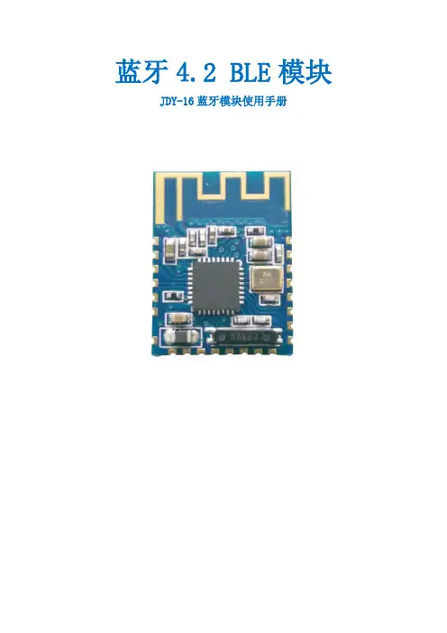
ZX-D29单模测试套装使用手册版本:V1.0日期:2023/02/10目录目录1ZX-D29测试套装介绍 (2)1.1概述 (2)1.2底板引脚示意图 (3)2ZX-D29测试步骤 (4)2.1AT指令测试 (4)2.2APP/微信小程序测试 (5)2.2.1、微信小程序测试 (5)2.2.2、安卓BLE APP测试 (7)2.2.3、苹果BLE APP测试 (8)3联系我们 (10)1.1概述ZX-D29测试套装是为了方便客户测试而提供的一套测试工具,工具包含(一根microUSB数据线+一个蓝牙模块带底板+USB转串口板)。
如下图:蓝牙模块带底板USB转串口板1.2底板引脚示意图蓝牙模块带底板引脚说明:STATE:连接状态脚,未连接时低电平输出,连接后高电平输出(可悬空)RXD:UART输入口TXD:UART输出口GND:电源地VCC:电源脚,输入电压范围 3.2-6VKEY:按键脚,低电平短按断开连接,长按3秒恢复出厂设置(可悬空)蓝牙模块USB转串口板RXD<--------->TXDTXD<--------->RXDVCC<--------->3V3GND<--------->GNDSTATE<--------->悬空KEY<--------->悬空注意:串口交叉连接2.1AT指令测试1)、将USB转串口板通过USB线连接到电脑,若设备管理器的端口未识别到串口需安装串口驱动。
驱动链接:/data/CH340G_USB.zip2)、打开”智兴微串口调试助手”软件,默认波特率为9600,右侧为AT指令区,可直接点数字发送,若使用其他串口工具时,指令结尾需要加上一个enter回车键(包含\r\n 回车换行)-且只能加一个回车键。
智兴微串口链接:/data/uart_tool.zip 例如:点右侧第一条”AT”指令发送,串口接收区将会返回”OK”应答2.2APP/微信小程序测试2.2.1、微信小程序测试1)、微信小程序二维码图片,或微信搜索小程序名”蓝牙串口透传”2)、微信小程序搜索连接操作步骤3)、微信小程序与蓝牙模块数据收发2.2.2、安卓BLE APP测试1)、下载安卓”蓝牙BLE助手安卓.apk”APP进行安装链接:/data/android_ble_tool.apk2)、APP搜索连接3)、APP与蓝牙模块数据收发2.2.3、苹果BLE APP测试1)、苹果应用商店app store下载APP”LightBlue”2)、苹果APP搜索连接3)、苹果APP与蓝牙模块数据收发ZX-D29单模测试套装使用手册深圳市智兴微科技有限公司10 深圳市智兴微科技有限公司官方官网:样品购买:公司地址:深圳市宝安区福永街道兴围锦灏大厦1912。
Blackfin Debugger Release 09.2023Blackfin DebuggerTRACE32 Online HelpTRACE32 DirectoryTRACE32 IndexTRACE32 Documents ......................................................................................................................ICD In-Circuit Debugger ................................................................................................................Processor Architecture Manuals ..............................................................................................Blackfin ....................................................................................................................................Blackfin Debugger (1)Introduction (4)Brief Overview of Documents for New Users4 Demo and Start-up Scripts5 Location of Debug Connector5Warning (5)Quick Start JTAG (6)Troubleshooting (8)SYStem.Up Errors8FAQ (8)Configuration (9)System Overview9Blackfin specific SYStem Commands (10)SYStem.CONFIG Configure debugger according to target topology10 Daisy-Chain Example13 TapStates14 SYStem.CONFIG.CORE Assign core to TRACE32 instance15 SYStem.CPU CPU type selection16 SYStem.JtagClock JTAG clock selection17 SYStem.LOCK Lock and tristate the debug port17 SYStem.MemAccess Real-time memory access (non-intrusive)18 SYStem.Mode System mode selection19 SYStem.Option.IMASKASM Interrupt disable19 SYStem.Option.IMASKHLL Interrupt disable20Breakpoints (21)Software Breakpoints21 On-chip Breakpoints21 Breakpoint in ROM21Example for Breakpoints22 Memory Classes (23)CPU specific TrOnchip Commands (24)JTAG Connector (25)Blackfin DebuggerVersion 10-Oct-2023 IntroductionThis document describes the processor specific settings and features for the Blackfin Embedded Media Processor. TRACE32-ICD supports all Blackfin devices which are equipped with the JT AG debug interface.Please keep in mind that only the Processor Architecture Manual (the document you are reading at the moment) is CPU specific, while all other parts of the online help are generic for all CPUs supported by Lauterbach. So if there are questions related to the CPU, the Processor Architecture Manual should be your first choice.If some of the described functions, options, signals or connections in this Processor Architecture Manual are only valid for a single CPU the name is added in brackets.Brief Overview of Documents for New UsersArchitecture-independent information:•“Training Basic Debugging” (training_debugger.pdf): Get familiar with the basic features of a TRACE32 debugger.•“T32Start” (app_t32start.pdf): T32Start assists you in starting TRACE32 PowerView instances for different configurations of the debugger. T32Start is only available for Windows.•“General Commands” (general_ref_<x>.pdf): Alphabetic list of debug commands.Architecture-specific information:•“Processor Architecture Manuals”: These manuals describe commands that are specific for the processor architecture supported by your Debug Cable. T o access the manual for your processorarchitecture, proceed as follows:-Choose Help menu > Processor Architecture Manual.•“OS Awareness Manuals” (rtos_<os>.pdf): TRACE32 PowerView can be extended for operating system-aware debugging. The appropriate OS Awareness manual informs you how to enable theOS-aware debugging.Demo and Start-up ScriptsLauterbach provides ready-to-run start-up scripts for known Blackfin based hardware.To search for PRACTICE scripts, do one of the following in TRACE32 PowerView:•Type at the command line: WELCOME.SCRIPTS•or choose File menu > Search for Script.Y ou can now search the demo folder and its subdirectories for PRACTICE start-up scripts(*.cmm) and other demo software.Y ou can also manually navigate in the ~~/demo/blackfin/ subfolder of the system directory ofTRACE32.Location of Debug ConnectorLocate the debug connector on your target board as close as possible to the processor to minimize the capacitive influence of the trace length and cross coupling of noise onto the JT AG signals. WarningSignal LevelThe debugger output voltage follows the target voltage level. It supports a voltage range of 0.4…5.2V. ESD ProtectionNOTE:T o prevent debugger and target from damage it is recommended to connect ordisconnect the debug cable only while the target power is OFF.Recommendation for the software start:•Disconnect the debug cable from the target while the target power is off.•Connect the host system, the TRACE32 hardware and the debug cable.•Start the TRACE32 software.•Connect the debug cable to the target.•Switch the target power ON.Power down:•Switch off the target power.•Disconnect the debug cable from the target.Quick Start JTAGStarting up the debugger is done as follows:1.Select the device prompt B: for the ICD Debugger, if the device prompt is not active after the TRACE32 software was started.2.Select the CPU type to load the CPU specific settings.3.Enter debug mode:This command resets the CPU and enters debug mode. After the execution of this command access to the registers and to memory is possible. Before performing the first access to external SDRAM or FLASH the External Bus Interface Unit (EBIU) must be configured.4.The following command sequence is for the BF537 processor and configures the SDRAM controller with default values that were derived for maximum flexibility. They work for a system clock frequency between 54MHz and 133MHz.In the example a ST M29W320DB flash device is used in 16-bit mode. All four memory banks and CLKOUT are enabled.B:SYStem.CPU BF537SYStem.Up; configure SDRAM controllerData.Set 0xFFC00A1sLONG 0x0091998D Data.Set 0xFFC00A14 %WORD 0x0025Data.Set 0xFFC00A1C %WORD 0x03A0; EBIU_SDGCTL ; EBIU_SDBCTL ; EBIU_SDRRC; enable all flash memory banks and clock outData.Set 0xFFC00A00 %WORD 0x00FF; EBIU_AMGCTL; ST M29W320DB flash device in 16-bit modeFLASH.Create 1. 0x20000000--0x20003FFF 0x4000 AM29LV100 Word FLASH.Create 1. 0x20004000--0x20007FFF 0x2000 AM29LV100 Word FLASH.Create 1. 0x20008000--0x2000FFFF 0x8000 AM29LV100 Word FLASH.Create 1. 0x20010000--0x203FFFFF 0x10000 AM29LV100 Word5.Load the program.Data.LOAD.Elf demo.dxe; The file demo.dxe is in ELF format The option of the Data.LOAD command depends on the file format generated by the compiler. A detailed description of the Data.LOAD command is given in the “General Commands Reference”. The start-up sequence can be automated using the programming language PRACTICE. A typical start sequence is shown below. This sequence can be written to a PRACTICE script file (*.cmm, ASCII format) and executed with the command DO<file>.B::; Select the ICD device promptWinClear; Delete all windowsSYStem.CPU BF537; select the processorSYStem.Up; Reset the target and enter debug modeData.Load.Elf sieve.dxe; Load the applicationRegister.Set PC main; Set the PC to function mainList.Mix; Open disassembly window *) Register.view; Open register window *) PER.view; Open window with peripheral register *) Break.Set sieve; Set breakpoint to function sieveBreak.Set 0x1000 /p; Set on-chip breakpoint to address 1000; Refer to the restrictions in; On-chip Breakpoints.*) These commands open windows on the screen. The window position can be specified with the WinPOS command.TroubleshootingSYStem.Up ErrorsThe SYStem.Up command is the first command of a debug session where communication with the target is required. If you receive error messages while executing this command this may have the following reasons.All The target has no power.All There are additional loads or capacities on the JTAG lines.All The JTAG clock is too fast.FAQPlease refer to https:///kb.Configuration System OverviewBlackfin specific SYStem CommandsSYStem.CONFIG Configure debugger according to target topologyThe four parameters IRPRE, IRPOST , DRPRE, DRPOST are required to inform the debugger about the T AP controller position in the JT AG chain, if there is more than one core in the JT AG chain (e.g. ARM + DSP). The information is required before the debugger can be activated e.g. by a SYStem.Up . See Daisy-chain Example .For some CPU selections (SYStem.CPU ) the above setting might be automatically included, since the required system configuration of these CPUs is known.T riState has to be used if several debuggers (“via separate cables”) are connected to a common JT AG port at the same time in order to ensure that always only one debugger drives the signal lines. T APState and TCKLevel define the T AP state and TCK level which is selected when the debugger switches to tristate mode. Please note: nTRST must have a pull-up resistor on the target, TCK can have a pull-up or pull-down resistor, other trigger inputs need to be kept in inactive state.Format:SYStem.CONFIG <parameter> <number_or_address>SYStem.MultiCore <parameter> <number_or_address> (deprecated)<parameter>:CORE <core><parameter>:(JTAG):DRPRE <bits>DRPOST <bits>IRPRE <bits>IRPOST <bits>DAPDRPOST <bits>DAPDRPRE <bits>DAPIRPOST <bits>DAPIRPRE <bits>TAPState <state>TCKLevel <level>TriState [ON | OFF ]Slave [ON | OFF ]DEBUGPORTTYPE [JTAG | SWD ]SWDPIDLEHIGH [ON | OFF ]SWDPTargetSel <value>CORE For multicore debugging one TRACE32 PowerView GUI has to be startedper core. To bundle several cores in one processor as required by thesystem this command has to be used to define core and processorcoordinates within the system topology.Further information can be found in SYStem.CONFIG.CORE.… DRPOST <bits>Defines the TAP position in a JT AG scan chain. Number of TAPs in theJTAG chain between the TDI signal and the TAP you are describing. InBYPASS mode, each TAP contributes one data register bit. See possibleTAP types and example below.Default: 0.… DRPRE <bits>Defines the TAP position in a JT AG scan chain. Number of TAPs in theJTAG chain between the TAP you are describing and the TDO signal. InBYPASS mode, each TAP contributes one data register bit. See possibleTAP types and example below.Default: 0.… IRPOST <bits>Defines the TAP position in a JT AG scan chain. Number of InstructionRegister (IR) bits of all TAPs in the JT AG chain between TDI signal andthe TAP you are describing. See possible T AP types and example below.Default: 0.… IRPRE <bits>Defines the TAP position in a JT AG scan chain. Number of InstructionRegister (IR) bits of all TAPs in the JTAG chain between the T AP you aredescribing and the TDO signal. See possible TAP types and examplebelow.Default: 0.TAPState(default: 7 = Select-DR-Scan) This is the state of the TAP controller whenthe debugger switches to tristate mode. All states of the JTAG T APcontroller are selectable.TCKLevel (default: 0) Level of TCK signal when all debuggers are tristated. TriState(default: OFF) If several debuggers share the same debug port, thisoption is required. The debugger switches to tristate mode after eachdebug port access. Then other debuggers can access the port. JT AG:This option must be used, if the JTAG line of multiple debug boxes areconnected by a JTAG joiner adapter to access a single JTAG chain. Slave(default: OFF) If more than one debugger share the same debug port, allexcept one must have this option active.JTAG: Only one debugger - the “master” - is allowed to control the signalsnTRST and nSRST (nRESET).DEBUGPORTTYPE [JTAG | SWD]It specifies the used debug port type “JT AG”, “SWD”. It assumes the selected type is supported by the target.Default: JT AG.SWDPIdleHigh [ON | OFF]Keep SWDIO line high when idle. Only for Serialwire Debug mode. Usually the debugger will pull the SWDIO data line low, when no operation is in progress, so while the clock on the SWCLK line is stopped (kept low).Y ou can configure the debugger to pull the SWDIO data linehigh, when no operation is in progress by usingSYStem.CONFIG SWDPIdleHigh ONDefault: OFF.SWDPTargetSel<value>Device address in case of a multidrop serial wire debug port.Default: none set (any address accepted).Daisy-Chain ExampleBelow, configuration for core C.Instruction register length of •Core A: 3 bit •Core B: 5 bit •Core D: 6 bitSYStem.CONFIG.IRPRE 6.; IR Core D SYStem.CONFIG.IRPOST 8.; IR Core A + B SYStem.CONFIG.DRPRE 1.; DR Core D SYStem.CONFIG.DRPOST 2.; DR Core A + BSYStem.CONFIG.CORE 0. 1.; Target Core C is Core 0 in Chip 1Core A Core B Core CCore D TDOTDI Chip 0Chip 1TapStates0Exit2-DR1Exit1-DR2Shift-DR3Pause-DR4Select-IR-Scan5Update-DR6Capture-DR7Select-DR-Scan8Exit2-IR9Exit1-IR10Shift-IR11Pause-IR12Run-Test/Idle13Update-IR14Capture-IR15Test-Logic-ResetSYStem.CONFIG.CORE Assign core to TRACE32 instance Format:SYStem.CONFIG.CORE<core_index><chip_index>SYStem.MultiCore.CORE<core_index><chip_index> (deprecated) <chip_index>:1 (i)<core_index>:1…kDefault core_index: depends on the CPU, usually 1. for generic chipsDefault chip_index: derived from CORE= parameter of the configuration file (config.t32). The COREparameter is defined according to the start order of the GUI in T32Start with ascending values.T o provide proper interaction between different parts of the debugger, the systems topology must bemapped to the debugger’s topology model. The debugger model abstracts chips and sub cores of these chips. Every GUI must be connect to one unused core entry in the debugger topology model. Once the SYStem.CPU is selected, a generic chip or non-generic chip is created at the default chip_index.Non-generic ChipsNon-generic chips have a fixed number of sub cores, each with a fixed CPU type.Initially, all GUIs are configured with different chip_index values. Therefore, you have to assign thecore_index and the chip_index for every core. Usually, the debugger does not need further information to access cores in non-generic chips, once the setup is correct.Generic ChipsGeneric chips can accommodate an arbitrary amount of sub-cores. The debugger still needs information how to connect to the individual cores e.g. by setting the JT AG chain coordinates.Start-up ProcessThe debug system must not have an invalid state where a GUI is connected to a wrong core type of a non-generic chip, two GUIs are connected to the same coordinate or a GUI is not connected to a core. The initial state of the system is valid since every new GUI uses a new chip_index according to its CORE= parameter of the configuration file (config.t32). If the system contains fewer chips than initially assumed, the chips must be merged by calling SYStem.CONFIG.CORE.SYStem.CPU CPU type selection Format:SYStem.CPU <cpu><cpu>:BF531 | BF532 | BF533 | BF534…Default selection: BF534.Selects the CPU type.SYStem.JtagClock JT AG clock selection Format:SYStem.JtagClock [<frequency>]SYStem.BdmClock<frequency>(deprecated)Default frequency: 1MHz.Selects the JT AG port frequency (TCK). Any frequency up to 50MHz can be entered, it will be generated by the debuggers internal PLL.For CPUs which come up with very low clock speeds it might be necessary to slow down the JT AGfrequency. After initialization of the CPUs PLL the JT AG clock can be increased.SYStem.LOCK Lock and tristate the debug port Format:SYStem.LOCK [ON | OFF]Default: OFF.If the system is locked, no access to the debug port will be performed by the debugger. While locked, the debug connector of the debugger is tristated. The main intention of the SYStem.LOCK command is to give debug access to another tool.SYStem.MemAccess Real-time memory access (non-intrusive) Format:SYStem.MemAccess Denied | StopAndGo | BTCBTC“BTC” allows a non-intrusive memory access while the core is running, if aBackground T elemetry Channel (BTC) is defined in your application. Anyinformation on how to create such a channel can be found in AnalogDevices’ VisualDSP++ user’s manual. The JT AG clock speed should be asfast as possible to get good performanceDenied Real-time memory access during program execution to target is disabled.StopAndGo Temporarily halts the core(s) to perform the memory access. Each stoptakes some time depending on the speed of the JT AG port, the number ofthe assigned cores, and the operations that should be performed.SYStem.Mode System mode selectionFormat:SYStem.Mode <mode>SYStem.Attach (alias for SYStem.Mode Attach)SYStem.Down (alias for SYStem.Mode Down)SYStem.Up (alias for SYStem.Mode Up)<mode>:DownGoAttachUpDown Disables the debugger.Go Resets the target with debug mode enabled and prepares the CPU fordebug mode entry. After this command the CPU is in the system.upmode and running. Now, the processor can be stopped with the breakcommand or if a break condition occurs.Attach User program remains running (no reset) and the debug interface isinitialized.Up Resets the target and sets the CPU to debug mode. After execution ofthis command the CPU is stopped and prepared for debugging.StandBy Not supported.NoDebug Not supported.SYStem.Option.IMASKASM Interrupt disable Format:SYStem.Option.IMASKASM [ON | OFF]Mask interrupts during assembler single steps. Useful to prevent interrupt disturbance during assembler single stepping.SYStem.Option.IMASKHLL Interrupt disable Format:SYStem.Option.IMASKHLL [ON | OFF]Mask interrupts during HLL single steps. Useful to prevent interrupt disturbance during HLL single stepping.BreakpointsThere are two types of breakpoints available: software breakpoints and on-chip breakpoints. Software BreakpointsSoftware breakpoints are the default breakpoints. A special breakcode is patched to memory so it only can be used in RAM or FLASH areas.There is no restriction in the number of software breakpoints.On-chip BreakpointsThe Blackfin processor has a total of six instruction and two data on-chip breakpoints.A pair of two breakpoints may be further grouped together to form a range breakpoint. A range breakpointcan be including or excluding. In the first case the core is stopped if an address in the range is detected, in the second case the core is stopped when an address outside of the range is observed.Breakpoint in ROMWith the command MAP.BOnchip<range> it is possible to inform the debugger about ROM(FLASH,EPROM) address ranges in target. If a breakpoint is set within the specified address range the debugger uses automatically the available on-chip breakpoints.Example for BreakpointsAssume you have a target with FLASH from 0x20000000 to 0x200FFFFF and RAM from 0x0 to 0x1000000. The command to configure TRACE32 correctly for this configuration is: Map.BOnchip 0x20000000--0x200FFFFFThe following breakpoint combinations are possible.Software breakpoints:Break.Set 0x0 /Program; Software Breakpoint 1Break.Set 0x1000 /Program; Software Breakpoint 2On-chip breakpoints:Break.Set 0x20000100 /Program; On-chip Breakpoint 1Break.Set 0x2000ff00 /Program; On-chip Breakpoint 2Memory ClassesThe following memory classes are available: Memory Class DescriptionP ProgramD DataCPU specific TrOnchip CommandsThe TrOnchip command group is not available for the Blackfin debugger.JTAG ConnectorSignal Pin Pin SignalGND12EMU-N/C34GNDVDDIO56TMSN/C78TCKN/C910TRST-N/C1112TDIGND1314TDOJTAG Connector Signal Description CPU Signal TMS JTAG-TMS,TMSoutput of debuggerTDI TDI JTAG-TDI,output of debuggerTCK TCK JTAG-TCK,output of debugger/TRST /TRST JTAG-TRST,output of debuggerTDO TDO JTAG-TDO,input for debugger/EMU JTAG Emulation Flag /EMUVDDIO VDDIO This pin is used by the debugger to sense the targetI/O voltage and to set the drive levels accordingly. Ifthe sensed voltage level is too low (e.g. target has nopower) the debugger powers down its drivers toprevent the target from damage.。
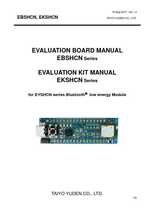
EVALUATION BOARD MANUALEBSHCN SeriesEVALUATION KIT MANUALEKSHCN Seriesfor EYSHCN series BluetoothⓇlow energy ModuleIntroductionThis evaluation board is applicable for Taiyo Yuden’s Bluetooth®low energy module, EYSHCN Series.Mounted moduleEYSHCN Series (9.6mm x 12.9mm x 2.0mm_MAX)Nordic nRF52832 / ARM® Cortex™-M4F 32 bit processor49-pin Land Grid Array / 30GPIOs / SWD- Basic Module -Taiyo Yuden writes SoftDevice to this product.The user can develop unique application for the module.Serial UART interface and power supply are possiblewith one USB cable. And this board has the SWDconnector terminal for software development.EBSHCN SeriesUSBEvaluation board circuit schematicPlease cut these 6 lines on the boardif you want to separate U1 and U2.Evaluation board layout1) All pin headers are 2.54mm pitch. And distance between CN3 and CN4 is 15.24mm . 2) CN3,4,5,6,8, C4,6,10-12, L1, R5-7,9,10, SB1-7, TP1 are not mounted (N.M.). 3) D1 (LED): 3.3V Indicator 4) D2 (LED): UART TX Indicator 5) D3 (LED): UART RX Indicator6) SW1 (Push button): Module Reset (active low)Silkscreen Printing(for CN4: GPIOs, SWDand DC powersupplyCN7: RF Connector U.FL-R-SMT (HIROSE)CN9: NFCPin DescriptionsHow to useIt is very easy just to tie this board to the PC with a USB cable. It is not necessary to change the setting of the board. The power supply of the module supplies by default 3.3V from 3V3OUT of FT232RQ.For software developmentNordic-DK and Use caseNordic-DK/eng/Products/Bluetooth-Smart-Bluetooth-low-energy/nRF52-DKminiUSBSWDEBSHCN SeriesCN1 supports the connection of the 10 pin Nordic-nRF52DKNordicMaster control paneletc.nRF51-DongleMEMO1) Current measurmentTo measure the current, please cut the shorting 1pin and 2 pin of CN6. And connect an ampere-meter between the pins of connector CN6 to monitor the current directly.2) About the power supply of the moduleWhen you use external power supply, please supply power from 15 and 16pin of CN3. On this configuration, please cut the short circuit 1pin and 2pin of CN5 in order to separate 3V3OUT of FT232RQ.3) USB to serial UART interfaceIt needs to install driver of FT232RQ to use USB for UART interface. The drivers are available on FTDI website./Drivers/D2XX.htmIn addition, by the application development, please assign GPIO as follows.4) Size and Coordinate information。

桂林NEC西安分公司 2011年7月日电通信有限公司西安分公司-设备设置手册系列目1. 简录述 ...................................................................................................................... 3 2. 系统要求和硬件连接 ............................................................................................. 4 3. LCT 连接和登录 ..................................................................................................... 4 4. 设置步骤 ................................................................................................................. 6 iPasolink 设置可以支持 E1,STM-1,以太网业务单独或混合传输。
......... 6 1- 设备配置(Equipment Configuration) ............................................................... 9 2-射频配置(Radio Configuration) ........................................................................ 12 3-网管设置(Network Management) ..................................................................... 15 4-预置-Modem 设置 ............................................................................................. 16 5-预置-以太网功能设置 (ETH function) ........................................................... 17 7-预置-时钟同步设置 .......................................................................................... 25 8-维护-设备日期时间设置 .................................................................................. 26 6. 其他常用菜单 ....................................................................................................... 27 6.1 测量收发信电平 ............................................................................................. 27 6.2 当前\历史性能数据监测 ............................................................................... 27 6.3 环回操作 ........................................................................................................ 29 6.4 设备硬\软启动 ............................................................................................... 30 6.5 其他功能 ......................................................................................................... 30 1)菜单说明: ..................................................................................................... 32 2日电通信有限公司西安分公司-设备设置手册系列1. 简述iPASOLINK 200型微波设备是集成TDM交换、 分组交换及微波光纤特性于一体的数字微 波系统,是汇聚下一代分组IP微波高集成化产品。
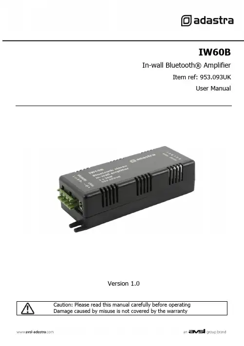
IW60BIn-wall Bluetooth® AmplifierItem ref: 953.093UKUser ManualVersion 1.0Caution: Please read this manual carefully before operatingDamage caused by misuse is not covered by the warrantyIntroductionThank you for choosing the Adastra IW60B in-wall amplifier for your discreet audio installation. This unit is designed to power wall or ceiling mounted speakers and receive audio via Bluetooth. Please read this manual to gain the best results from your product and avoid damage through misuse.SAFETY SYMBOL AND MESSAGE CONVENTIONSCAUTIONRISK OF ELECTRIC SHOCK DO NOT OPENAVISRISQUE DE CHOC ELECTRIQUE NE PASOUVRIRThis symbol indicates that dangerous voltage constituting a risk of electric shock ispresent within this unitThis symbol indicates that there are important operating and maintenance instructions inthe literature accompanying this unit.WarningTo prevent the risk of fire or electric shock, do not expose any components to rain or moisture.If liquids are spilled on the casing, stop using immediately, allow unit to dry out and have checked by qualified personnel before further use. Avoid impact, extreme pressure or heavy vibration to the case. No user serviceable parts inside – Do not open the case – refer all servicing to qualified service personnel.Safety•Check for correct mains voltage before connecting the power adaptor•Use only the power adaptor provided or an identical replacementPlacement•The IW60B can be installed in a ceiling or stud wall to power flush or surface mount speakers •The IW60B can also be surface mounted if necessary•Ensure adequate ventilation for cooling and keep away from combustible material or moisture •Ensure that the IW60B is within Bluetooth connection range of the sending deviceCleaning•Use a soft cloth with a neutral detergent to clean the housing as required•Use a vacuum cleaner to clear apertures and controls of any dust or debris build-ups•Do not use solvents for cleaning the unitConnectionsInstallationLocate the IW60B in the ceiling, wall or on the surface required. Tabs at each end of the housing can be used for securing with screws.Connect speakers using the supplied wires or equivalent by connecting “+” and “-” on the speaker to the relevant connection on the IW60B. The speaker connections are via screw terminals on a Euroblock, which can be removed for easy access whilst making connections.Important: Ensure that the load is no lower than 4Ω for each output.(e.g. 2 x 4Ω speakers… or… 2 pairs of 8Ω speakers wired in parallel)Ensure that the speakers can handle 30W from each output.If the IW60B is to be used with a wired audio line level input (instead of Bluetooth), connect this to the Euroblock terminals labelled “AUX IN” as shown on the Connections diagram above.Left positive connection (Lef t+) should be connected to “L”Right positive connection (Right+) should be c onnected to “R”Both negative connections (Left- and Right-) should be connected to “G”(G is the terminal for Ground connection – common for both Left and Right signals)Likewise, the Bluetooth or Aux input can be relayed to further IW60B or other amplifiers by connecting a line level output from the Euroblock terminals labelled “AUX OUT”AUX IN and AUX OUT connections should be made using shielded stereo audio cable and not speaker cable.OperationWhen powered up, the IW60B will be open for Bluetooth pairing.(a small LED will flash inside the housing)Ensure that only the first IW60B in an AUX OUT-IN daisy chain is powered up initially.This will ensure that all of the amps in the daisy chain receive the same audio.Search available Bluetooth devices on your smart phone or other sending device for a device with Bluetooth ID “IW60B-****” (where **** is a unique ID number for each unit)Select to pair and connect with this ID (rename if required on Android)When paired and connected, set the volume low on the smart phone or other sending device and play a track to check the sound through the speakersPower down the IW60B when not in use and isolate from the mains if not used for long periods of time.SpecificationsPower supply 12Vdc, 2000mA (adaptor included)Bluetooth version 4.0Output : rms @ 4Ω 2 x 30WMinimum impedance 4Ω per outputSpeaker outputs L-/L+/R-/R+ screw terminals (Euroblock)Auxiliary input L/G/R screw terminals (Euroblock)Auxillary output L/G/R screw terminals (Euroblock)Dimensions 124 x 40 x 27mmWeight 60g (excluding power adaptor)Disposal:The “Crossed Wheelie Bin” symbol on the product means that the product is classed as Electrical orElectronic equipment and should not be disposed with other household or commercial waste at the end of its useful life.The goods must be disposed of according to your local council guidelines.Errors and omissions excepted.。

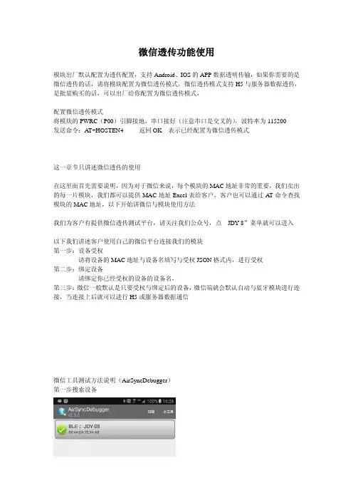
微信透传功能使用模块出厂默认配置为透传配置,支持Android、IOS的APP数据透明传输,如果你需要的是微信透传的话,请将模块配置为微信透传模式,微信透传模式支持H5与服务器数据透传,是批量购买的话,可以出厂给你配置为微信透传模式,配置微信透传模式将模块的PWRC(P00)引脚接地,串口接好(注意串口是交叉的),波特率为115200发送命令:AT+HOSTEN4 返回OK 表示已经配置为微信透传模式这一章节只讲述微信透传的使用在这里面首先需要说明,因为对于微信来说,每个模块的MAC地址非常的重要,我们卖出的每一片模块,我们都可以提供MAC地址Excel表给客户,客户也可以通过AT命令查找模块的MAC地址,以下开始讲微信与模块使用方法我们为客户有提供微信透传测试平台,请关注我们公众号,点“JDY-8”菜单就可以进入以下我们讲述客户使用自己的微信平台连接我们的模块第一步:设备受权请将设备的MAC地址与设备名填写与受权JSON格式内,进行受权第二步:绑定设备请绑定你已经受权的设备的设备名,第三步:微信一般默认是只要受权与绑定后的设备,微信端就会默认自动与蓝牙模块进行连接,当连接上后就可以进行H5或服务器数据通信微信工具测试方法说明(AirSyncDebugger)第一步搜索设备第二步选择AirSync协议第三步选择手动测试第四步:通过以上步骤表示已经通过微信连接第五步:你点一下那下一步进入以下界面,收发数据以上界面可以向模块发数据,就是相当微信给蓝牙模块发数据第6步:接收数据,也就是模块发给微信的数据查看日志里面可以看到模块发给微信的数据,红色框里面就是微信接收到模块的数据,是3131323233 这个数据我可以随便发的,。

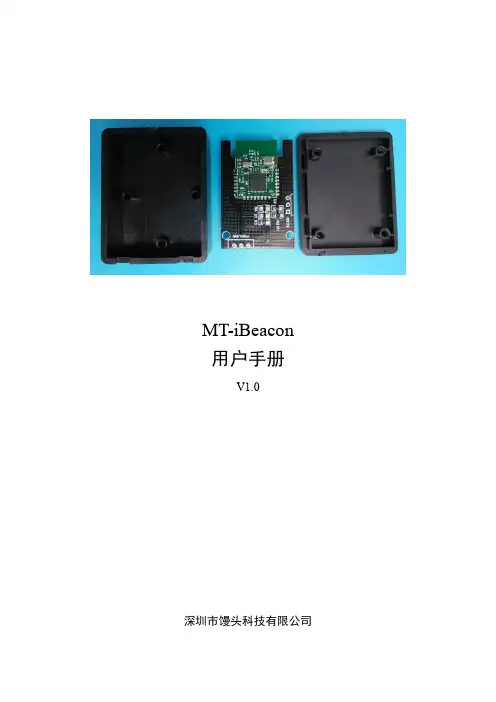
MT-iBeacon用户手册V1.0深圳市馒头科技有限公司版本更新记录目录第1章参数设置 (4)第2章测距功能 (16)第1章参数设置1. 从App Store中下载LightBlue应用到iPhone手机上,安装并打开,点击左下角Central,使手机蓝牙工作在主机模式,开始搜索附近的iBeacon设备(从机设备),即可搜索到由深圳市馒头科技倾力推出的室内定位利器——MT-iBeacon。
2. 点击MT-iBeacon图标连接上设备进行相应的设置。
可以在服务发现里面看到,设备信息,电量信息以及服务UUID。
3. 设备信息展示,此服务用于查看设备的相关信息。
4. 查询设备电量。
此服务用于查询设备的剩余电量,如图所示为剩余100%的电量。
5. 服务UUID。
进入服务UUID,可以看到总共有7个服务,这7个服务的功能见下表1-1 服务功能表。
表1-1 服务功能表图1-1 设置UUID图1-2 设置major图1-3 设置minor图1-4 设置MeasuredPower图1-5 设置发射功率图1-6 设置广播间隔图1-7 设置LED状态第2章测距功能1. 从App Store中下载Locate iB应用到iPhone手机上,安装并打开,可以看到界面如下图。
2. 点击Locate iBeacons按钮,进入下一级菜单,搜索当前可连接的iBeacon设备。
3. 测距校准。
1) 点击Visible iBeacon进入下级菜单,屏幕上有显示Major、Minor、RSSI、Accuracy等信息,下面有两个按钮,Distance——测距,Calibrate——校准。
点击Calibrate进行校准。
2) 根据提示,需要将手机放在离iBeacon 1米处的位置,然后点击,并且保持30s~60s的时间,才能完成校准。
3) 校准中。
4) 校准完成!4. 测距。
校准完成后,回到上一级菜单,点击Distance开始测距。
ozone j-link debugger使用方法Ozone J-Link Debugger 是一种用于调试嵌入式系统的工具,支持多种不同的调试接口和芯片架构。
以下是使用 Ozone J-Link Debugger 的基本方法:1. 下载和安装Ozone J-Link Debugger:访问Segger 官方网站,并下载 Ozone J-Link Debugger 的最新版本。
安装程序将会指导您完成安装过程。
2. 连接目标设备和调试器:将 J-Link 调试器通过 USB 线缆连接到您的开发主机上。
确保您的目标设备也用正确的方式连接到调试器上,这可能需要使用适配器或者正确连接调试接口。
3. 打开 Ozone J-Link Debugger:在安装完成后,您可以在开始菜单或者桌面上找到 Ozone J-Link Debugger,并启动它。
4. 配置目标设备:在 Ozone J-Link Debugger 中,选择"Project" 菜单,并点击 "Options"。
在打开的对话框中,选择合适的目标设备和调试接口。
5. 配置调试连接:在 "Options" 对话框中选择 "Debug" 选项卡,并选择正确的调试器。
您可以指定速度和其他选项来优化连接设置。
6. 配置符号文件:在 "Options" 对话框中选择 "Code" 选项卡,并选择适当的符号文件。
这样可以帮助 Ozone J-Link Debugger 解析和显示源代码。
7. 启动调试会话:点击 Ozone J-Link Debugger 主界面的"Connect" 按钮,Ozone 将尝试与目标设备建立连接。
如果连接成功,您将会看到一些调试和运行控制按钮变为可用状态。
8. 运行和调试程序:在成功连接后,您可以使用 Ozone J-Link Debugger 的各种功能来运行和调试您的程序。
SKRCommunication Debugger for RobotINSTRUCTION MANUALCommunication DebuggerModule* ........................................................ 1 unit Communication Cable 3m .......................1 unit Ref. 0029626AC Adapter .................................................... 1 unit Ref. 0028084USB A/B Cable ............................................1 unit Ref. 0021042*Download the Robot Control software, available inEU USPacking ListThe following items are included:This manual corresponds to the following references:SKR-A2FeaturesPower Supply ConnectorUSB-B ConnectorGreen LED (JBC Device Activity)Green LED (PLC Activity)SKR facilities the integration of the following JBC Devices in automated soldering processes:- UCR - Control Unit for Robot (serial communication RS-232*)- SFR - Solder Feeder for Robot (serial communication RS-232*)- CLMR/CLMRP - Tip Cleaner for Robot (on/off switch input*)*See corresponding “Communication Protocol” at /jbcsoftware.html.360 mm80 mm100 mm130 mm130 mmpara manuales - color gris200 mmConnection ModesSKR allows two connection modes, the Control Mode and the Sniffer Mode . In both modes, the SKR and a PC are needed. PC must have the Robot Control previously installed (download at /jbcsoftware.html ).- Control Mode : This mode is used to command/get answered communications frames, which are sent between the PC and the JBC Device.- Sniffer Mode : This mode is used to intercept the communication frames sent/answered between the Robot/PLC and the JBC Device. This mode also facilitates the debugging of the Robot Control software by Frame decoding and visualization in real-time.Assembly: Control Mode1. Connect the PC and SKR using the USB A/B Cable.2. Connect the JBC Device and SKR using the Communications Cable.3. Connect SKR to the mains connection with the power supply cable. Blue LED indicates that the connection to the mains is established.4. The Push Button allows switching on/off the JBC Device by pushing it.When communications frames between PC and JBC Device are sent/answered, then the green LEDs will flash.JBCRobot Control SoftwareUCRControl Unit for RobotSKRCommunication Debugger for Roboteither4Assembly: Sniffer Mode1.Disconnect the Communications Cable from the JBC Device and connect it to SKR’s Communications Connector (male). 2. Connect the JBC Device and SKR using the Communications Cable included.3. Connect de PC and SKR using the USB A/B Cable.4. Connect SKR to the main connection with the power supply cable. Blue LED indicates that the connection to the main is established.When communications frames between PC and JBC Device are sent/answered, then the green LEDs will flash.For more information about the Robot Control software, download its manual at /jbcsoftware.html.SFRSolder Feeder for RobotUCRControl Unit for RobotPLC / RobotJBCRobot Control SoftwareSKRCommunication Debugger for Roboteither550 mm60 mm80 mm100 mm130 mm 130 mmpara manuales - color gris200 mm- Before carrying out maintenance, always allow the equipment to cool down.- Periodically check all cables and connections.- Replace any defective or damaged parts. Use original JBC spare parts only.- Repairs should only be performed by JBC and authorized technical service.Maintenance- Do not use the device for any other purpose.- The main cable must be plugged into approved bases. Make sure that it is properly grounded before use. When unplugging it, hold the plug, not the wire.- Be sure that the power supply is disconnected before changing any spare parts.- Be careful with the fumes produced when soldering.- Keep your workplace clean and tidy. Wear appropriate protection glasses and gloves when working to avoid personal injury.SafetyIt is imperative to follow safety guidelines to prevent electricshock, injury, fire or explosion.6Notes750 mm60 mm80 mm100 mm130 mm 130 mmpara manuales - color gris200 mmThis product should not be thrown in the garbage.In accordance with the European directive 2012/19/EU, electronic equipment at the end of its life must be collected and returned to an authorized recycling facility.of defective parts and labour.Warranty does not cover product wear or misuse. In order for the warranty to be valid, equipment must be returned, postage paid, to the dealer where it was purchased.0021922-200123SpecificationsSKRCommunication Debugger for Robot Ref. SKR-A - AC Adapter: Input Voltage Range: 100-240V ~ 50/60Hz IMax. Input Current: 2A Output Voltage: 24VMax. Output Current: 2A - Connections: USB connector type B Power connectorCommunications connector (male)Communications connector (female)- Total Net Weight: 505 g / 1.11 lb- Total Package Dimensions / Weight: 246 x 184 x 42 mm / 567 g (L x W x H) 9.69 x 7.24 x 1.65 / 1.25 lb Complies with CE standards.ESD safe.。
TABLE OF CONTENTSChapter 1. R elease Overview (1)1.1. Product Overview (1)1.2. Release Components (1)1.3. Supported Platforms and Operating Systems (1)Chapter 2. N ew or Modified Features (3)2.1. What's New in Release 2017 (3)Chapter 3. T roubleshooting Tips and Known Limitations (4)3.1. Debugging Issues (4)Chapter 4. C ontact Information (5)Welcome to Release 2017 of the PGDBG® debugger for x86-compatible processor-based workstations, servers, and clusters running versions of Linux, Apple macOS, or Microsoft Windows operating systems. This document describes late-breaking information not included in the current printing of the PGI Debugger User's Guide.1.1. Product OverviewPGDBG is licensed software available from The Portland Group. You must agree to an End-User License Agreement when you install the software.PGDBG supports debugging programs running on local and remote systems.Local debuggingIf you want to debug a program running on the system where you have launched PGDBG, you are doing local debugging and you need license keys on that local system.Remote debuggingIf you want to debug a program running on a system other than the one on which PGDBG is launched, you are doing remote debugging and you need license keys on both the local and the remote systems.1.2. Release ComponentsRelease 2017 includes the multi-thread graphical debugger for debugging applications.1.3. Supported Platforms and Operating SystemsPGDBG is supported on six platforms.Support for 32-bit development was deprecated in PGI 2016 and will no longer be available as of the PGI2017 release. PGI 2017 will only be available for 64-bit operating systems and will not include the ability todebug 32-bit applications on either 32- or 64-bit operating systems.Release Overview‣64-bit Linux – supported on 64-bit Linux operating systems running on a 64-bit x86 compatible processor.‣64-bit macOS – supported on 64-bit Apple macOS operating systems running on a 64-bit Intel processor-based Macintosh computer.‣64-bit Windows – supported on 64-bit Microsoft Windows operating systems running on a 64-bit x86-compatible processor.This section provides information about the new or modified features of Release 2017 of the PGI Debugger.2.1. What's New in Release 2017A number of problems are corrected in every release. Refer to /support/ release_tprs.htm for a complete and up-to-date table of technical problem reports (TPRs) fixed in recent releases of the PGI compilers and tools. This table contains a summary description of each problem as well as the version in which it was fixed.This section contains information about known limitations, documentation errors, and corrections.For up-to-date information about the state of the current release, refer to the frequently asked questions (FAQ) section at: /support/index.htm.3.1. Debugging IssuesThe following are known debugging issues across platforms:‣Debugging of PGI Unified Binaries™, that is, 64-bit programs built with more than one -tp option, is not fully supported. The names of some subprograms are modified during compilation, and PGDBG does not translate these names back to the names used in theapplication source code.For detailed information on how to debug PGI Unified Binary files, refer to/support/tool.htm.‣The debugger is not currently supported on OS X version 10.12 (Sierra).‣There is a known issue when debugging on OS X 10.11 (El Capitan); the debugger will generate warning messages when running to a breakpoint. These warning messages do not affect the ability of the debugger to debug your application and will be addressed in a future release.‣When debugging on a Windows 10 system, you may notice that the debugger captures extra "Worker" threads whether or not your application is multi-threaded. These threads are from the Windows 10 thread pool; the loader is taking advantage of multiple cores to load DLLs and initializes the application faster. When you are debugging a multi-threaded application and want to switch control between your program's threads, use the "threads" command to determine that thread's ID in the debugger.You can contact PGI at:20400 NW Amberwood Drive Suite 100Beaverton, OR 97006Or electronically using any of the following means:Fax: +1-503-682-2637Sales: ****************WWW: The PGI User Forum is monitored by members of the PGI engineering and support teams as well as other PGI customers. The forum newsgroups may contain answers to commonly asked questions. Log in to the PGI website to access the forum:/userforum/index.phpMany questions and problems can be resolved by following instructions and the information available at our frequently asked questions (FAQ) site:/support/faq.htmSubmit technical support requests through the online form at:https:///support/support_request.phpPGI documentation is available at /resources/docs.htm.NoticeALL NVIDIA DESIGN SPECIFICATIONS, REFERENCE BOARDS, FILES, DRAWINGS, DIAGNOSTICS, LISTS, AND OTHER DOCUMENTS (TOGETHER AND SEPARATELY, "MATERIALS") ARE BEING PROVIDED "AS IS." NVIDIA MAKES NO WARRANTIES, EXPRESSED, IMPLIED, STATUTORY, OR OTHERWISE WITH RESPECT TO THE MATERIALS, AND EXPRESSLY DISCLAIMS ALL IMPLIED WARRANTIES OF NONINFRINGEMENT, MERCHANTABILITY, AND FITNESS FOR A PARTICULAR PURPOSE.Information furnished is believed to be accurate and reliable. However, NVIDIA Corporation assumes no responsibility for the consequences of use of such information or for any infringement of patents or other rights of third parties that may result from its use. No license is granted by implication of otherwise under any patent rights of NVIDIA Corporation. Specifications mentioned in this publication are subject to change without notice. This publication supersedes and replaces all other information previously supplied. NVIDIA Corporation products are not authorized as critical components in life support devices or systems without express written approval of NVIDIA Corporation. TrademarksPGI Workstation, PGI Server, PGI Accelerator, PGF95, PGF90, PGFORTRAN, and PGI Unified Binary are trademarks; and PGI, PGHPF, PGF77, PGCC, PGC++, PGI Visual Fortran, PVF, PGI CDK, Cluster Development Kit, PGPROF, PGDBG, and The Portland Group are registered trademarks of NVIDIA Corporation in the U.S. and other countries. Other company and product names may be trademarks of the respective companies with which they are associated.Copyright© 2013–2017 NVIDIA Corporation. All rights reserved.。
微信蓝牙外设协议Project BlueShadowV1.0.3Tencent Confidential文档变更日志目录概要...................................................... 错误!未定义书签。
整体架构............................................... 错误!未定义书签。
主要功能............................................... 错误!未定义书签。
蓝牙BLE模拟成流................................ 错误!未定义书签。
协议...................................................... 错误!未定义书签。
1绑定........................................................................................................错误!未定义书签。
扫码绑定............................................................................................错误!未定义书签。
蓝牙扫描绑定....................................................................................错误!未定义书签。
2扫描和连接............................................................................................错误!未定义书签。
3 流 ...........................................................................................................错误!未定义书签。
微信蓝牙外设协议beta 微信蓝牙外设协议beta协议双方:甲方:(公司名称/个人姓名)_______________________地址:___________________________联系电话:____________________身份证号:________________________邮箱:________________________乙方:微信(腾讯公司)地址:深圳市南山区腾讯大厦身份证号:________________________ 邮箱:________________________鉴于甲方拥有开发微信蓝牙外设的技术和资源,而乙方拥有微信平台,双方本着平等、自愿、互信的原则,达成以下协议:第一条协议内容1.甲方承诺为乙方提供蓝牙外设的接口定义和开发文档,并确保其技术在一定范围内的稳定性和可靠性。
2.甲乙双方确立合作期限至合作项目开发结束。
3.各方同意遵守中国相关法律法规,不得利用微信蓝牙外设进行非法活动和侵犯他人的合法权益等行为。
4.本协议的条款、附属协议及所有修改、补充协议,将共同构成协议主体,对各方具有效力。
第二条权利义务1.甲方的权利和义务:a.按照乙方的要求,在约定时间内提供接口定义和开发文档,确保其技术的稳定性和可靠性。
b.拥有自主开发微信蓝牙外设的权利,并对开发过程中产生的技术、数据等享有全部的知识产权。
c.保证开发过程中不存在抄袭、侵犯他人知识产权等行为,否则应承担相应的法律责任。
d.保证开发的蓝牙外设能够稳定运行,对由于技术问题等造成的损失,承担相应的法律责任。
2.乙方的权利和义务:a.根据甲方提供的技术开发接口,开展相关开发工作,并与甲方保持紧密的沟通,确保合作进度和项目顺利完成。
b.使用微信平台为甲方开发的蓝牙外设提供必要的技术支持和服务。
c.保证开发过程中不存在泄漏甲方专有技术的行为,否则应承担相应法律责任。
d.甲方开发出的蓝牙外设按照乙方的要求发布上线,并承担公示运营所需的相关法律责任。