CVA2404T中文资料
- 格式:pdf
- 大小:50.12 KB
- 文档页数:3

CCTV各种设备参数CCTV各种设备参数目录CCTV各种设备参数 (1)1.HUS (6)1.1中心管理服务器HUS-VMS (6)1.2网络存储系统HUS-NVR-5100A (7)1.3视频存储磁盘阵列HUS-NVR-EC16 (9)1.4中心管理服务器HUS-XACT100 (11)1.5中心管理服务器HUS-XPRO-MAS(4.1.0) (13)1.6中心管理扩展服务器HUS-XPRO-SLA(4.1.0) (16)1.7中心管理容灾备份系统HUS-XPRO-RPK(本地支持)(4.1.0) (17)1.8中心管理容灾备份系统HUS-XPRO-RDB(异地支持)(4.1.0) (20)1.9中心管理服务器HUS-XTRE-MAS(4.1.0) (23)1.10中心管理容灾备份系统HUS-XTRE-RPK(本地支持)(4.1.0) (26)1.11中心管理服务器HUS-XACT100(4.1.0) (30)1.12中心管理服务器HUS-XACT100S(4.1.0) (33)1.13中心管理服务器HUS-XACT50S(4.1.0) (37)1.14网络存储系统HUS-NVR-5100A(4.1.0) (40)1.15视频存储磁盘阵列HUS-NVR-EC16(4.1.0) (42)1.16网络存储系统HUS-IPS (45)1.17流媒体服务器HUS-IPS-STM (45)1.18IPSAN主柜:HUS-IPS-5100S (46)1.19IPSAN扩展柜:HUS-IPS-EC16S (47)1.20IPSAN主柜:HUS-IPS-5100D (48)1.21IPSAN扩展柜:HUS-IPS-EC16D (49)2.视频编解码器 (50)2.1视频编码器HVR-9000 (50)2.2视频解码器HUS-D4 (52)2.3视频编码器HUSS-E4 (53)2.4视频编码器HUSS-E4V (55)2.5视频编码器HUSS-E1 (56)2.6视频解码器HUSS-D1 (57)2.7单路高清视频解码器HD-NDE-1H11 (58)2.8四路高清视频解码器HD-NDE-4H11 (59)2.9数字视频编码器HUSS-E2X (61)2.10数字视频编码器HUSS-E4X (63)2.11数字视频编码器HUSS-E8X (66)3.IP摄像机 (69)3.1网络半球摄像机HIVDC-100P (69)3.2室内半球网络摄像机HIDC-0100 (70)3.3防暴半球网络摄像机HIVDC-0105 (72)3.4百万像素网络半球摄像机HD3MDIP (75)3.5日夜转换网络固定摄像机HICC-100P/HICC-100PT (77)3.6网络枪式摄像机HICC-0100 (78)3.7百万像素网络固定摄像机HICC-130P (80)3.826倍户外全天候高性能网络快球摄像机HSD-261P-NET (82)3.936倍户外全天候宽动态网络快球摄像机HSD-361PW-NET (84)4.Pioneer系统摄像机 (86)4.1百万像素室外防暴半球网络摄像机HIVDC-P-0105 (86)4.2百万像素室内半球网络摄像机HIDC-P-0100-43 (88)4.3百万像素室内半球网络摄像机HIDC-P-0100V (90)4.4全帧速高清室内半球网络摄像机HIDC-P-1100 (93)4.5百万像素网络摄像机HICC-P-0100 (95)4.6全帧速高清网络摄像机HICC-P-1100 (97)4.723倍室外网络快球摄像机HISD-P-0231 (100)4.836倍室外宽动态网络快球摄像机HISD-P-0361W (102)5.IP高清摄像机(2011.08新发布) (106)5.1720p高清宽动态网络枪型摄像机HICC-1300W (106)5.2720p高清网络半球型摄像机HIDC-1300V (108)5.3720p高清网络半球型摄像机HIDC-1300W (110)5.4720p高清网络半球型摄像机HIVDC-1300W (112)5.5720p高清网络高速球型摄像机HISD-1181W (114)5.61080p高清网络枪型摄像机HICC-2300 (117)5.71080p高清网络枪型摄像机HICC-2300T (119)5.81080p高清网络半球型摄像机HIDC-2300V (121)5.91080p高清网络半球型摄像机HIVDC-2300V (123)5.101080p高清网络高速球型摄像机HISD-2201W (126)5.11720P高清网络枪型摄像机HICC-1100 (128)5.12720P高清真实日夜转换网络枪型摄像机HICC-1100T (130)5.13720P高清室内网络半球型摄像机HIDC-1100PV (133)5.14720P高清真实日夜转换室内网络半球型摄像机HIDC-1100PTV (135)5.15720P高清网络半球型摄像机HIVDC-1105PV (138)5.16720P高清真实日夜转换网络半球型摄像机HIVDC-1105PTV (140)6.模拟半球摄像机 (143)6.1电梯专用半球摄像机HDC-505P-25 (143)6.2高分辨率彩色半球摄像机HDC-505PV (144)6.3电梯专用摄像机HDC-890P-36 (145)6.4半球摄像机HDC-790P-36/60 (146)6.5半球摄像机HDC-690P-36/60 (147)6.6半球摄像机HDC-890PV (148)6.7半球摄像机HDC-895PV (150)6.8半球摄像机HDC-795PV (151)6.9宽动态防暴半球摄像机HVD-890PV (152)6.10宽动态防暴半球摄像机HVD-890PT (153)6.11宽动态防暴半球摄像机HVD-890PI (154)6.12宽动态红外半球摄像机HVD-890PVIA-E (156)6.13电梯专用半球摄像机HDC-690P-25 (157)6.14室内日夜型半球摄像机HDC-690PV (158)6.15600线半球摄像机HDC-6605PV (160)6.16650线半球摄像机HDC-8655PV (161)6.17650线真实日夜转换半球摄像机HDC-8655PTV (163)6.18650线真实日夜转换防暴红外半球摄像机HDC-8655PTV (164)6.19650线真实日夜转换宽动态红外半球摄像机HDC-8655PTV (166)6.20电梯半球摄像机HDC-6605P-28 (168)7.模拟枪式固定摄像机 (170)7.1摄像机VCC-320 (170)7.2强光抑制摄像机HCC-685PT (170)7.3高分辨率日夜转换摄像机HCC-690P (171)7.4彩色固定摄像机HCC-645P (172)7.5彩色固定摄像机HCC-745P (173)7.6高分辨率日夜转换摄像机HCC-745PTW (175)7.7日夜转换固定摄像机HCC-795P (176)7.8日夜转换固定摄像机HCC-795PT (177)7.9日夜转换固定摄像机HCS-895X (177)7.10日夜转换固定摄像机HCD-895X (178)7.11600线真实日夜转换枪型摄像机HCC-6605PT (179)7.12650线枪型摄像机HCC-8655P (180)7.13650线真实日夜转换枪型摄像机HCC-8655PT (182)7.14650线真实日夜转换防暴红外枪型摄像机HCC-8655PTVI (183)7.15650线真实日夜转换宽动态枪型摄像机HCC-8655PTW (185)7.16650线日夜转换宽动态枪型摄像机HCC-8655PW (186)7.17700线真实日夜转换宽动态枪型摄像机HCC-8705PTW (188)7.18摄像机HCC-248 (189)7.191/2”CCD高分辨率彩色摄像机HCC-290P-E (191)7.201/2”CCD高分辨率彩色摄像机HCC-295P (192)7.21650线超高分辨率摄像机HCC-960P-VR (193)7.22650线超高分辨率摄像机HCC-965P-VR (195)7.23650线超高分辨率摄像机HCC-960PT-VR (196)7.24650线超高分辨率摄像机HCC-965PT-VR (197)7.2525倍日夜转换宽动态一体化摄像机HZC-252P-VR (198)7.2636倍日夜转换宽动态一体化摄像机HZC-363P-VR (200)8.模拟快球摄像机 (202)8.1日夜型快球摄像机HSDN-352PXE (202)8.2快球摄像机HSDN-251PS (203)8.3日夜型快球摄像机HSDC-251PXE (204)8.425x宽动态快球摄像机HSDC-252PA-E (205)8.536x宽动态快球摄像机HSDC-363PA-E (207)8.6室外一体化快球HSD-261P (209)8.7室外一体化快球HSD-261PW (210)8.8室外一体化快球HSD-361P (212)8.9室外一体化快球HSD-361PW (213)9.矩阵系统 (215)9.1Maxpro-NET矩阵系统 (215)9.2MegaPIT通道切换装置HS10PIT (219)9.3VB矩阵系统 (220)9.4VideoBolX CPU控制模块 (222)9.5视频输入模块 (222)9.6视频输出模块 (223)9.7协议转换器PIT (223)9.8报警输入输出模块 (224)9.9数据扩展器 (225)9.10设备控制配置程序(HVBCFG) (225)9.11图形控制软件(HVBGUI) (225)9.12网络服务器软件(HVBNET) (226)10.键盘 (227)10.1HJC5000矩阵控制键盘 (227)11.硬盘录像机 (229)11.116通道D1全实实嵌入式硬盘录像机HD-16DVR-D (229)11.216通道硬盘录像机HD-16DVR-7016 (231)11.3HD-JC-010键盘——DCS操控设备 (232)11.4HD-NDE-4010 4通道视频解码器——视频输出设备 (233)12.智能分析编码器 (234)12.1智能分析编码器HV AE-0100 (234)12.2智能分析编码器HV AE-0400 (235)1. HUS1.1中心管理服务器HUS-VMSHUS-VMS是系统核心服务器,主要包含数据中心管理、报警事件管理、视频流管理、预案编程管理等。
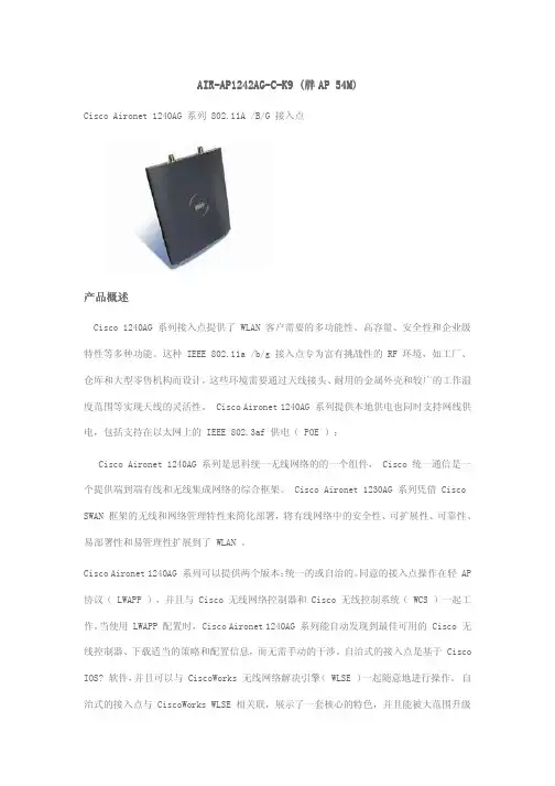
AIR AIR--AP1242AG AP1242AG--C -K9 (K9 (胖胖AP 54M)AP 54M)Cisco Aironet 1240AG 系列 802.11A /B/G 接入点产品概述产品概述Cisco 1240AG 系列接入点提供了 WLAN 客户需要的多功能性、高容量、安全性和企业级特性等多种功能。
这种 IEEE 802.11a /b/g 接入点专为富有挑战性的 RF 环境,如工厂、仓库和大型零售机构而设计,这些环境需要通过天线接头、耐用的金属外壳和较广的工作温度范围等实现天线的灵活性。
Cisco Aironet 1240AG 系列提供本地供电也同时支持网线供电,包括支持在以太网上的 IEEE 802.3af 供电( POE );Cisco Aironet 1240AG 系列是思科统一无线网络的的一个组件, Cisco 统一通信是一个提供端到端有线和无线集成网络的综合框架。
Cisco Aironet 1230AG 系列凭借 Cisco SWAN 框架的无线和网络管理特性来简化部署,将有线网络中的安全性、可扩展性、可靠性、易部署性和易管理性扩展到了 WLAN 。
Cisco Aironet 1240AG 系列可以提供两个版本:统一的或自治的。
同意的接入点操作在轻 AP 协议( LWAPP ),并且与 Cisco 无线网络控制器和 Cisco 无线控制系统( WCS )一起工作。
当使用 LWAPP 配置时, Cisco Aironet 1240AG 系列能自动发现到最佳可用的 Cisco 无线控制器、下载适当的策略和配置信息,而无需手动的干涉。
自治式的接入点是基于 Cisco IOS? 软件,并且可以与 CiscoWorks 无线网络解决引擎( WLSE )一起随意地进行操作。
自治式的接入点与 CiscoWorks WLSE 相关联,展示了一套核心的特色,并且能被大范围升级到充分有利的优势,便于作为 Cisco 统一无线网络必要的发展条件。
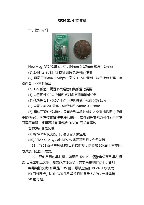
RF2401中文资料一、模块介绍NewMsg_RF2401B (尺寸:34mm X 17mm 板厚:1mm)(1) 2.4Ghz 全球开放ISM 频段免许可证使用(2) 最高工作速率1Mbps,高效GFSK调制,抗干扰能力强,特别适合工业控制场合(3) 125 频道,满足多点通信和跳频通信需要(4) 内置硬件CRC 检错和点对多点通信地址控制(5) 低功耗1.9 - 3.6V 工作,待机模式下状态仅为1uA(6) 内置2.4Ghz 天线,体积小巧 34mm X 17mm(7) 模块可软件设地址,只有收到本机地址时才会输出数据(提供中断指示),可直接接各种单片机使用,软件编程非常方便(8) 内置专门稳压电路,使用各种电源包括DC/DC 开关电源均有很好的通信效果(9) 标准DIP间距接口,便于嵌入式应用(10)RFModule-Quick-DEV 快速开发系统,含开发板(11)与51系列单片机P0口连接时候,需要加10K的上拉电阻,与其余口连接不需要。
(12)其他系列的单片机,如果是5V的,请参考该系列单片机IO 口输出电流大小,如果超过10mA,需要串联电阻分压,否则容易烧毁模块! 如果是3.3V的,可以直接和RF2401模块的IO口线连接。
比如AVR系列单片机如果是5V的,一般串接2K的电阻。
二、接口电路说明:(1)VCC脚接电压范围为 1.9V~3.6V之间,不能在这个区间之外,超过3.6V将会烧毁模块。
推荐电压3.3V左右。
(2)除电源VCC和接地端,其余脚都可以直接和普通的5V单片机IO口直接相连,无需电平转换。
当然对3V左右的单片机更加适用了。
(3)硬件上面没有SPI的单片机也可以控制本模块,用普通单片机IO口模拟SPI不需要单片机真正的串口介入,只需要普通的单片机IO口就可以了,当然用串口也可以了。
(4)6脚,12脚为接地脚,需要和母板的逻辑地连接起来(5)排针间距为100mil,标准DIP插针,如果需要其他封装接口,比如密脚插针,或者其他形式的接口,可以联系我们定做。
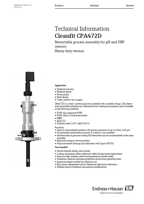
Products Solutions Services TI00403C/07/EN/13.1371227170Technical InformationCleanfit CPA472DRetractable process assembly for pH and ORPsensorsHeavy duty versionApplication•Chemical industry•Biodiesel plants•Power plants•Plant design•Tanks, process vats or pipesCPA472D is a robust, universal process assembly with a modular design. This heavy-duty retractable assembly can withstand harsh working environments and is availablein the following materials:•PVDF and conductive PVDF•PVDF, Alloy C22electrode holder•PEEK•Alloy C22•Stainless steel 1.4571 (AISI 316 Ti)Functions•Move to measurement position with process pressures of up to 10 bar (145 psi)•No pneumatic positioning in process if a sensor is not installed•Gel electrodes or pressure-overlay KCl electrodes can be accommodated in the sameassembly•Electrode rinsing in service position•Fully automated cleaning and calibration with Topcal CPC310Your benefits•Service-friendly design saves money•Locking mechanism offers additional safety during sensor replacement•Pressure-tight stainless steel housing enhances system safety•Maximum chemical resistance properties ensure long operating times•Immersion depth suitable for industrial use•Easy sensor replacement allows Memosens laboratory calibration•Flexible choice of material and practical modificationsCleanfit CPA472D2Endress+HauserFunction and system designFunctionWith the retractable assembly Cleanfit CPA472D you can realize reliable pH and ORP measurements. The retractable assembly is designed as a chemically resistant assembly for the chemical industry, process engineering and plant construction. Without interrupting the process you can perform the following manual or pneumatic operations for the electrode:•separate from the process and move into the rinse chamber •rinse with water or cleaning solution •keep wet during operation pauses •dismount •sterilize •or calibrateThe modular assembly is especially designed for applications with aggressive chemicals, hightemperatures and pressures up to 10 bar. Therefore the assembly housing (A) is made of stainless steel. The parts in contact with medium like the rinse chamber (PVDF) are installed between the structural housing parts (B) with machine screws. This ensures the dimensional stability.The assembly Cleanfit CPA472D is available in PEEK, PVDF, conductive PVDF, Alloy C22 and stainless steel 1.4571 (AISI 316 Ti). It has only three modules in contact with medium: Rinse chamber (C), electrode holder (E) and raised face (D). Thanks to the modular design you can combine materials as required for your application. The assembly can be used for temperatures up to 140 °C (284 °F) and pressures up to 6 bar (87psi). Please see the pressure and temperature diagram.The novel electrode holder (4) supports an easy installation of the retractable pipe (7).You have the choice of two immersion depths with gel and KCl electrodes:•the standard version (immersion depth up to 146 mm (5.75 "), applicable with 225 mm gel electrodes, 360mm gel electrodes with adapter or 360 mm KCl electrodes) or•the long version (immersion depth up to 280 mm (7.87 "), applicable with 360 mm gel electrodes). The following process connections are available:•DN 50 / DN 80 / ANSI 2" / JIS for tanks•DN 50/DN 80 for flow assembly pipes with sight glass assembly •G 1¼ with union nut for metal versionsCleanfit CPA472DEndress+Hauser 3Safety stopThe pneumatic retractable assembly CPA472D is fitted with an integrated safety stop mechanism (patented). This mechanism prevents the assembly from entering the process if the electrode is not installed but the compressed air supply is connected.The safety stop mechanism is based on the air channels and works as follows:The electrode is not installed and the command is given to "Move to measuring position":Pressure cannot build up since the compressed air enters the upper section of the electrode holder via the air channels and escapes via the retraction pipe. This is signalled by a loud noise.The electrode is installed and the command is given to "Move to measuring position":The electrode closes the air channels and seals off the chamber above the electrode thread. The upper part of the cylinder is filled with compressed air. Pressure builds and the electrode holder enters the process.This means that an electrode must be installed in the assembly before the assembly can move to the measuring position.A Stainless steel housing, screwed 3Compressed air "Measurement"B Rinse chamber armoring 4Electrode holder (head) with guidance for installation of the retractable pipeC Rinse chamber 5ElectrodeD Raising face 6Splash protection capE Electrode holder 7Retractable pipe 8Limit switch "Service"1Compressed air "Service"9Stop lock bolt2Rinse connection10Limit switch "Measurement"Cleanfit CPA472D4Endress+HauserInternal sealInternal seal- position of the sealsMeasuring system without controlMeasuring system without control (example)12Cleanfit assembly with pH/ORP sensor Special measuring cable 34Transmitter Liquiline M CM42 or Transmitter Mycom S CPM153Cleanfit CPA472DEndress+Hauser 5Measuring system with pneumatical controlMeasuring system with pneumatic control12345678pH/ORP sensor Assembly CleanfitTransmitter Mycom CPM153Special measuring cableCommunication and extension cables Power supply Mycom Power supply CPG310Control unit CPG3109101112131415Canisters for cleaning and buffer solutions Superheated steam/water/cleaning solutions (optional)Rinse blockRinse water valve Power/signal cable Air hoses MediumCleanfit CPA472D6Endress+HauserInstallationInstallation instructionsPermitted orientations depending on the sensor usedThe assembly is designed for installation in pipes with nominal diameters of DN 80 or larger. To install it in pipes with the nominal diameter DN 50, please use the flow assembly with integrated sight glass (see "Accessories")Installation examples with recommended installation angle (glass electrodes)A TankB Flow assembly DN 50/80C Horizontal pipe minimum DN 80DAscending pipe minimum DN 80Pneumatic connection for automatic operationRequirements:•air pressure of 5 to 6 bar (72.5 to 87 psi)•air must be filtered (40μm) and be free of water and oil •no continuous air consumption•minimum nominal diameter of the air lines: 4mm (0.16 ").NOTICEIf the air pressure can increase to above 6 bar (87 psi) (including any short pressure surges) the assembly can get damaged.‣Install a pressure-reducing valve upstream.‣We recommend you also use a pneumatic throttle for lower pressures. This results in a smootherassembly operation. Endress+Hauser offers such a throttle as an accessory (see chapter "Accessories").A Glass electrode:Installation angle of at least 15° from the horizontal BISFET pH-sensor Tophit:No restrictions, recommended 0 to 180°Cleanfit CPA472DEndress+Hauser 7Rinse water connectionThe rinse chamber allows you to clean the electrode with water or cleaning solution with a pressure of 2 to max. 6 bar (30 to max. 87 psi). When using water, you have to install a check valve and a filter (100 μm) at the inlet side. When you operate the assembly with pneumatic actuation and use acleaning solution, you have to install the chemically resistant ON/OFF valve (see "Accessories"). Install an outlet valve at the outlet side of the rinse chamber (see "Accessories").If the water pressure can increase to above 6 bar (87 psi) (including any short pressure surges) the assembly can get damaged.‣Install a pressure-reducing valve upstreamConnect the rinse connections to the in-house facilities via ball valves. If you do not use the rinse function, please leave the dummy plug installed.EnvironmentAmbient temperatureAmbient temperature not below 0 °C (32 °F).The maximum permissible temperature for electric limit position switches (NAMUR type) is 90°C (194°F).ProcessProcess temperature range 0 to 140 °C (32 to 284 °F)Process pressure range0 to max. 4bar (0 to max. 58 psi) overpressure for manual actuation 0 to 10 bar (0 to 145 psi) overpressure for pneumatic actuationPressure temperature diagramPressure temperature diagramCleanfit CPA472D8Endress+HauserMechanical constructionDimensionsAssembly version: long, for gel sensors A Length when extendedB Required mounting clearanceX364/366 mm (14.3/14.4") depending on flange sizeAssembly version: standard, for KCl sensors A Length when extendedB Required mounting clearanceX229/231 mm (9.02/9.09") depending on flange sizeCleanfit CPA472DEndress+Hauser 9Process connectionsProcess connections 1Flange DN 50 / DN 80 / ANSI 2" / JIS IS10K50A 2Internal thread G1¼For 425 mm gel sensors a special version with extra large immersion depth of 378 mm (14.9") is available. Order no. 71220488 / C-PA100525-40Assembly version: standard, for gel sensors A Length when extendedB Required mounting clearanceX229/231 mm (9.02/9.09") depending on flange sizeConnection A B C (standard) C (long)DN 50165/6.50125/4.92145/5.71280/11.0DN 80200/7.87160/6.30143/5.63278/10.94ANSI 2"152.4/6.00120.7/4.75145/5.71280/11.0JIS IS10K50A 155/6.10120/4.72147/5.79282/11.10G 1¼51/2.01---152/5.98287/11.30Dimensions in mm/inchCleanfit CPA472D10Endress+HauserSensorsWeight Depending on the material: 7.5 to 12.0 kg (16.54 to 26.46 lbs)MaterialsRinse connections2 x G¼ (internal) or 2 x NPT ¼" (internal) or2 x pipe 8 x 60 Swagelok as nozzle Limit position switchesThe position of the input resp. the output may be different from the figure. Please, refer to the marks at the limit position switch: "1" is the input (in), "2" is the output (out).Standard version Gel sensors, ISFET KCl sensors225 mm 360 mm Long version Gel sensors, ISFET 360 mmIn contact with medium:Electrode holder Rinse chamber and raised face SealsPEEK, PVDF, conductive PVDF, Alloy C22, stainless steel 1.4571 (AISI 316 Ti)PEEK, PVDF, conductive PVDF, Alloy C22, stainless steel 1.4571 (AISI 316 Ti)EPDM/FPM (Viton)/FFKM (Kalrez ®)Not in contact with medium:Housing SealsLimit position switches (NAMUR-type)Stainless steel 1.4404 (AISI 316 L)FPMFront surface PBT, cable PVC Handle/protection capPVCPneumatic:3/2 way valve; thread M 12 x 1;connection for hoses with OD = 6 mm (0.24")Electric:inductive (NAMUR type); cable length: 10 m (32.8 ft);housing material: stainless steel; thread M 12 x 1;nominal voltage: 8 V0II 1G EEx ia IIC T6; switching distance: 2 mm, flushLimit position switches, left:pneumatic (1=compressed air inlet,2=compressed air outlet) right:electric (NAMUR)Cleanfit CPA472DEndress+Hauser 11Pneumatic connections (depending on version)Pneumatic connections for automatic assembly actuationThe assembly Cleanfit CPA472D is operated with an air pressure of 5 to 6 bar (72.5 to 87 psi). The air must be filtered (40 μm) and free from water and oil. There is no continuous pressure demand. The air lines must have a minimum nominal diameter of 4 mm.NOTICEIf the air pressure can increase to above 6 bar (87 psi) (including any short pressure surges) the assembly can get damaged.‣Install a pressure-reducing valve upstream.‣We recommend you also use a pneumatic throttle for lower pressures. This results in a smootherassembly operation..Certificates and approvalsLimit switches The inductive limit switches meet the requirements of DIN EN 60 947-5-6 (NAMUR).Inspection certificateInspection certificate 3.1 acc. to EN 10204 on demand.1Compressed air for "service"3Limit switch "service"2Compressed air for "measurement"4Limit switch "measurement"Cleanfit CPA472D12Endress+HauserOrdering informationOrder codeEnter the following address in your browser to access the product page:/cpa472d 1.2.Click "Configure this product".3.The configurator opens in a separate window. You can now configure your device and receive the complete order code that applies for the device.4.Afterwards, export the order code as a PDF or Excel file. To do so, click the appropriate button at the top of the page.Product structureDrive type and limit contact switchesA Manual without limit contact switchesB Pneumatic without limit contact switchesC Pneumatic with 2 pneumatic limit contact switchesD Pneumatic with 2 electric Ex limit contact switchesEPneumatic with 1 electric Ex limit contact switch, position "Measuring"Assembly version, locking3Internal seal, service position4Internal seal, service position + measuring positionElectrode typeA For gel electrodes / ISFET sensors, 225 mmB For gel electrodes / ISFET sensors, 360 mm CFor liquid KCl electrodes, 360 mmImmersion depth1max 146 mm (5.75")2max 280 mm (11.02")Assembly material (in contact with medium)B PEEKC PVDFD PVDF, conductiveE PVDF, electrode holder Alloy C22H Stainless steel 1.4571; 316Ti JAlloy C22 incl. 3.1Seal material (in contact with medium)1EPDM 2FPM Viton ®3FFKM KALREZ ®Process connectionD DN 50 flange (acc. to EN 1092), stainless steelE DN 80 flange (acc. to EN 1092), stainless steelF 2" ANSI flange, stainless steelG Thread G1¼ internal (only with materials H/J)J Flange JIS IS10K50AYSpecial version acc. to customer specificationRinse connection1Without rinse connection3With rinse fitting 2 x G ¼ internal thread 4With rinse fitting 2 x NPT ¼" internal thread 5With rinse fitting 2 x pipe 8x60 mm Swagelok CPA472D-complete order codeCleanfit CPA472DEndress+Hauser 13Scope of deliveryThe scope of delivery comprises:•Cleanfit CPA472D assembly (ordered version)•Operating Instructions (English)Cleanfit CPA472D14Endress+HauserAccessoriesProcess adapterBuilt-in adapter DN 25•Stainless steel 1.4404•"Straight" version - Order No.: 51500328•"Inclined" version - Order No.: 51500327Build-in adapter A Build-in adapter, straight B Build-in adapter, inclinedCBuild-in adapter, CPA472D installedCleanfit CPA472DEndress+Hauser 15Welded fitting DN 50 (70 mm), inclined, material: 1.4571 (AISI 316 Ti);•order no. 71098682Welded fitting 1Flange DN 50 / PN16Dummy plug for G1¼ process connection,•Stainless steel 1.4435 (AISI 316L), FKM (Viton ®) seal, G1¼ internal thread; order no. 51502800Dummy plug for G¼ rinse connection,•SS 1.4404 (AISI 316L); order no. 50092264Anti-twist deviceAnti-twist device•Anti-twist device for CPA472D•Screw (5): stainless steel1.4404 (AISI 316 L)•Plate (3): PA 6 G black•Star-knob screw (1): thermoplast black and stainless steel 1.4305 (AISI 303)•Sleeves (2 and 3): PVC black •Order no. 71224451Anti-twist device 1Star-knob screw 2Distance sleeve 3Sleeve 4Plate 5ScrewCleanfit CPA472D16Endress+HauserWater filter and pressure reducerFilter set CPC310•Water filter (dirt trap) 100μm, complete, incl. angle bracket;•Order no. 71031661Pressure reducer kit•Complete, incl. manometer and angle bracket;•Order no. 51505755Hose nozzle•Hose nozzles for rinse connections G¼, DN 12,PVDF, 2 pieces;order no. 50090491Rinse chamber valve•Rinse chamber input valve, pneumatically ON - OFF, PVDF with bellows, connection G¼,(on request)Limit switchesSet of pneumatic limit position switches (2 pieces);•order no. 51502874Set of electric limit position switches, Ex and non-Ex (2 pieces);•order no. 51502873Pneumatic throttlePneumatic throttle for the reduction of the assembly moving speed,•G1/8 threaded connection •order no. 50036864Cleanfit CPA472DEndress+Hauser 17Sensors Glass electrodesOrbisint CPS11/CPS11D•pH sensor for process applications•Optional SIL version for connection to SIL approved transmitters •With dirt-repellent PTFE diaphragm•Ordering per product structure (--> Online configurator, /cps11 or /cps11d)•Technical Information TI00028C/07/ENOrbisint CPS12/CPS12D•ORP electrode for process applications •With dirt-repellent PTFE diaphragm•Ordering per product structure (--> Online configurator, /cps12 or /cps12d)•Technical Information TI00367C/07/ENCeraliquid CPS41/CPS41D •pH sensor•With ceramics diaphragm and liquid KCl electrolyte•Ordering per product structure (--> Online configurator, /cps41 or /cps41d)•Technical Information TI00079C/07/ENCeraliquid CPS42/CPS42D •ORP electrode•With ceramics diaphragm and liquid KCl electrolyte•Ordering per product structure (--> Online configurator, /cps42 or /cps42d)•Technical Information TI00373C/07/ENCeragel CPS71/CPS71D •pH sensor•With double chamber reference system and integrated bridge electrolyte•Ordering per product structure (--> Online configurator, /cps71 or /cps71d)•Technical Information TI00245C/07/ENCeragel CPS72/CPS72D •ORP electrode•With double chamber reference system and integrated bridge electrolyte•Ordering per product structure (--> Online configurator, /cps72 or /cps72d)•Technical Information TI00374C/07/ENOrbipore CPS91/CPS91D •pH sensor•With open aperture for media with high dirt load•Ordering per product structure (--> Online configurator, /cps91 or /cps91d)•Technical Information TI00375C/07/ENOrbipore CPS92/CPS92D •ORP sensor•With open aperture for media with high dirt load•Ordering per product structure (--> Online configurator, /cps92 or /cps92d)•Technical Information TI00435C/07/EN ISFET sensorsTophit CPS471/CPS471D•Sterilizable and autoclavable ISFET sensor for food and pharmaceuticals, process technology, •water treatment and biotechnology;•Ordering per product structure (--> Online configurator, /cps471 or /cps471d)•Technical Information TI283C/07/ENCleanfit CPA472D18Endress+HauserTophit CPS441/CPS441D•Sterilizable ISFET sensor for media with low conductivity, with liquid KCl electrolyte;•Ordering per product structure (--> Online configurator, /cps441 or /cps441d)•Technical Information TI352C/07/ENTophit CPS491/CPS491D•ISFET sensor with open aperture for media with high dirt load;•Ordering per product structure (--> Online configurator, /cps491 or /cps491d)•Technical Information TI377C/07/ENCableCPK9 measuring cable•For sensors with TOP68 plug-in head, for high-temperature and high-pressure applications, IP 68•Ordering acc. to product structure, see Technical Information (TI00118C/07/EN)CPK1 measuring cable•For pH/ORP electrodes with GSA plug-in head•Ordering acc. to product structure, see Technical Information (TI00118C/07/EN)CPK12 special measuring cable•For pH/ORP glass electrodes and ISFET sensors with TOP68 plug-in head•Ordering acc. to product structure, see Technical Information (TI00118C/07/EN)CYK10 Memosens data cable•For digital sensors with Memosens technologypH, redox, oxygen (amperometric), chlorine, conductivity (conductive)•Ordering acc. to product structure (-> online configurator, /cyk10)TransmitterLiquiline CM44x/CM44xR•Multiple-channel transmitter for the connection of digital sensors with Memosens technology •Field device or DIN rail device•Power supply: 100 to 230 V AC, 24 V AC/DC •Universally upgradeable •SD card slot•Ordering per product structure (--> Online configurator on product page)•Technical Information TI00444C/07/EN (CM44x) or TI01112C/07/EN (CM44xR)Liquiline CM42•Modular two-wire transmitter, stainless steel or plastic, field or panel instrument •Various Ex approvals (ATEX, FM, CSA, Nepsi, TIIS)•HART, PROFIBUS or FOUNDATION Fieldbus available•Ordering acc. to product structure, see Technical Information (TI381C/07/en)Liquisys CPM223/253•Transmitter for pH and ORP, field or panel-mounted housing •HART or PROFIBUS available•Ordering acc. to product structure, see Technical Information (TI194C/07/en)Mycom CPM153•Transmitter for pH and ORP, one or two channel version, Ex or non-Ex •HART or PROFIBUS available•Ordering acc. to product structure, see Technical Information (TI233C/07/en)Measuring, cleaning and calibration systemsTopcal CPC310•Fully automatic measuring, cleaning and calibration system; Ex or non-Ex •In-situ cleaning and calibration, automatic sensor monitoring•Ordering acc. to product structure, Technical Information TI404C/07/en Topclean CPC30•Fully automatic measuring and cleaning system; Ex or non-Ex •In-situ cleaning, automatic sensor monitoring•Ordering acc. to product structure, see Technical Information TI235C/07/enCleanfit CPA472DEndress+Hauser19。
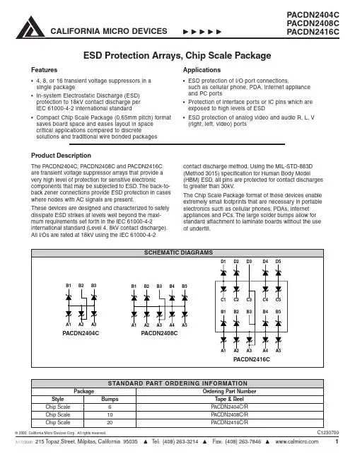
ESD Protection Arrays, Chip Scale PackageFeatures•4, 8, or 16 transient voltage suppressors in asingle package•In-system Electrostatic Discharge (ESD)protection to 18kV contact discharge perIEC 61000-4-2 international standard•Compact Chip Scale Package (0.65mm pitch) format saves board space and eases layout in space critical applications compared to discretesolutions and traditional wire bonded packagesProduct DescriptionThe PACDN2404C, PACDN2408C and PACDN2416C are transient voltage suppressor arrays that provide a very high level of protection for sensitive electronic components that may be subjected to ESD. The back-to-back zener connections provide ESD protection in cases where nodes with AC signals are present.These devices are designed and characterized to safely dissipate ESD strikes at levels well beyond the maxi-mum requirements set forth in the IEC 61000-4-2 international standard (Level 4, 8kV contact discharge). All I/Os are rated at 18kV using the IEC 61000-4-2Applications•ESD protection of I/O port connections,such as cellular phone, PDA, internet applianceand PC ports•Protection of interface ports or IC pins which are exposed to high levels of ESD•ESD protection of analog video and audio R, L, V (right, left, video) portscontact discharge method. Using the MIL-STD-883D (Method 3015) specification for Human Body Model (HBM) ESD, all pins are protected for contact discharges to greater than 30kV.The Chip Scale Package format of these devices enable extremely small footprints that are necessary in portable electronics such as cellular phones, PDAs, internet appliances and PCs. The large solder bumps allow for standard attachment to laminate boards without the use of underfill.*ESD applied between channel pin and ground, one at a time. All other channels are open. This parameter is guaranteed by design and characterizationTypical Solder Reflow Thermal Profile (No Clean Flux)Time (s)T e m p e r a t u r e (oC )Package DiagramsPin OrientationComponents are symmetrical, and do not require orientation to pin-1 found in conventional semiconductors. The part may be rotated 180° without affecting operation.0.65PACDN2404CPACDN2408CPACDN2416Cmmmm。
S P E C I F I C A T I O N24C02/24C04/24C08/24C16Version 1.0Two-wire Serial EEPROM2K bits (256 X 8) / 4K bits (512 X 8) / 8K bits (1024 X 8) / 16K bits (2048 X 8)▉FeaturesThe 24C02/24C04/24C08/24C16 provides 2048/4096/8192/16384 bits of serial electrically erasable and programmable read-only memory (EEPROM) organized as 256/512/1024/2048 words of 8 bits each. The device is optimized for use in many industrial and commercial applications wherelow-power and low-voltage operation are essential. The 24C02/24C04/24C08/24C16 is available in space-saving 8-lead PDIP, 8-lead SOP, and 8-lead TSSOP packages and is accessed via a two-wire serial interface.▉Pin ConfigurationTwo-wire Serial EEPROM2K bits (256 X 8) / 4K bits (512 X 8) / 8K bits (1024 X 8) / 16K bits (2048 X 8)▉Pin DescriptionsTwo-wire Serial EEPROM2K bits (256 X 8) / 4K bits (512 X 8) / 8K bits (1024 X 8) / 16K bits (2048 X 8)▉Pin Descriptions24C02, 2K SERIAL EEPROM: Internally organized with 32 pages of 8 bytes each, the 2K requires an 8-bit data word address for random word addressing.24C04, 4K SERIAL EEPROM: Internally organized with 32 pages of 16 bytes each, the 4K requires a 9-bit data word address for random word addressing.24C08, 8K SERIAL EEPROM: Internally organized with 64 pages of 16 bytes each, the 8K requires a 10-bit data word address for random word addressing.24C16, 16K SERIAL EEPROM: Internally organized with 128 pages of 16 bytes each, the 16K requires an 11-bit data word address for random word addressing.▉Device OperationTwo-wire Serial EEPROM 2K bits (256 X 8) / 4K bits (512 X 8) / 8K bits (1024 X 8) / 16K bits (2048 X 8)Two-wire Serial EEPROM2K bits (256 X 8) / 4K bits (512 X 8) / 8K bits (1024 X 8) / 16K bits (2048 X 8) The 2K, 4K, 8K and 16K EEPROM devices all require an 8-bit device address word following a start condition to enable the chip for a read or write operation (see to Figure 4 on page 7).The device address word consists of a mandatory "1", "0" sequence for the first four most significant bits as shown. This is common to all the Serial EEPROM devices.The next 3 bits are the A2, A1 and A0 device address bits for the 2K EEPROM. These 3 bits must compare to their corresponding hardwired input pins.The 4K EEPROM only uses the A2 and A1 device address bits with the third bit being a memory page address bit. The two device address bits must compare to their corresponding hardwired input pins. The A0 pin is no connect.The 8K EEPROM only uses the A2 device address bit with the next 2 bits being for memory page addressing. The A2 bit must compare to its corresponding hard-wired input pin. The A1 and A0 pins are no connect.The 16K does not use any device address bits but instead the 3 bits are used for memory page addressing. These page addressing bits on the 4K, 8K and 16K devices should be considered the most significant bits of the data word address which follows. The A0, A1 and A2 pins are no connect.The eighth bit of the device address is the read/write operation select bit. A read operation is initiated if this bit is high and a write operation is initiated if this bit is low.Upon a compare of the device address, the EEPROM will output a "0". If a compare is not made, the chip will return to a standby state.▉Write OperationsTwo-wire Serial EEPROM2K bits (256 X 8) / 4K bits (512 X 8) / 8K bits (1024 X 8) / 16K bits (2048 X 8) Read operations are initiated the same way as write operations with the exception that the read/write select bit in the device address word is set to "1". There are three read operations: current address read,random address read and sequential read.CURRENT ADDRESS READ: The internal data word address counter maintains the last address accessed during the last read or write operation, incremented by one. This address stays valid between operations as long as the chip power is maintained. The address "roll over" during read is from the last byte of the last memory page to the first byte of the first page. The address "roll over" during write is from the last byte of the current page to the first byte of the same page.Once the device address with the read/write select bit set to "1" is clocked in and acknowledged by the EEPROM, the current address data word is serially clocked out. The microcontroller does not respond with an input "0" but does generate a following stop condition (see Figure 7 on page 8).RANDOM READ: A random read requires a "dummy" byte write sequence to load in the data word address. Once the device address word and data word address are clocked in and acknowledged by the EEPROM, the microcontroller must generate another start condition. The microcontroller now initiates a current address read by sending a device address with the read/write select bit high. The EEPROM acknowledges the device address and serially clocks out the data word. The microcontroller does not respond with a "0" but does generate a following stop condition (see Figure 8 on page 8). SEQUENTIAL READ: Sequential reads are initiated by either a current address read or a randomTwo-wire Serial EEPROM 2K bits (256 X 8) / 4K bits (512 X 8) / 8K bits (1024 X 8) / 16K bits (2048 X 8)Two-wire Serial EEPROM2K bits (256 X 8) / 4K bits (512 X 8) / 8K bits (1024 X 8) / 16K bits (2048 X 8)l Absolute Maximum Stress RatingsDC Supply Voltage . . . . . . . . . . . . . . . . .-0.3V to +6.5V Input / Output Voltage . . . . . . . .GND-0.3V to V CC+0.3V Operating Ambient Temperature . . . . . -40℃to +85℃Storage Temperature . . . . . . . . . . . . -65℃to +150℃l CommentsStresses above those listed under "Absolute Maximum Ratings" may cause permanent damage to this device. These are stress ratings only. Functional operation of this device at these or any other conditions above those indicated in the operational sections of this specification is not implied or intended. Exposure to the absolute maximum rating conditions for extended periods may affect device reliability.Two-wire Serial EEPROM2K bits (256 X 8) / 4K bits (512 X 8) / 8K bits (1024 X 8) / 16K bits (2048 X 8)▉DC Electrical CharacteristicsApplicable over recommended operating range from TA = 25 ℃, f = 1.0 MHz, VCC = +1.8V Parameter Symbol Min. Typ. Max. Unit ConditionCI/O - - 8 pF VI/O = 0V Input/Output Capacitance(SDA)Input Capacitance (A0, A1,CIN - - 8 pF VIN = 0V A2, SCL)▉AC Electrical CharacteristicsTwo-wire Serial EEPROM2K bits (256 X 8) / 4K bits (512 X 8) / 8K bits (1024 X 8) / 16K bits (2048 X 8) Figure 10: SCL: Serial Clock, SDA: Serial Data I/OTwo-wire Serial EEPROM2K bits (256 X 8) / 4K bits (512 X 8) / 8K bits (1024 X 8) / 16K bits (2048 X 8)▉Write Cycle Timing。
氮封阀参数表全文共四篇示例,供读者参考第一篇示例:氮封阀参数表氮封阀是一种常用的工业阀门,常用于氮气介质的控制和封闭。
氮封阀有多种型号和规格,根据不同的工作压力、介质和温度要求,可以选择合适的氮封阀来实现准确的控制和封闭作用。
下面是一份关于氮封阀参数表的详细介绍,包括常用型号、规格、工作压力、介质和温度范围等信息。
型号:NFV-001规格:DN50-DN800工作压力:10-40 bar介质:氮气温度范围:-40℃至+80℃适用领域:化工、石油、天然气等工业领域特点:耐高压、耐腐蚀、稳定性好介质:氮气、氧气混合气体特点:快速开关、防爆防火、可靠性高特点:耐低温、密封性好、操作便捷以上是关于氮封阀参数表的简要介绍,氮封阀作为重要的工业阀门,广泛应用于各种工业领域,其性能参数和规格需根据具体需求进行选择,确保其可靠性和安全性。
希望以上信息对您有所帮助,如有需要,可咨询专业的氮封阀厂家或供应商获取更多详细信息。
第二篇示例:氮封阀是一种用于液体或气体管道系统中的关键部件,用以控制氮气的流动和压力,确保管道系统的安全运行。
氮封阀参数表是用来记录氮封阀的各项参数和性能指标的表格,能够帮助工程师和操作人员了解氮封阀的规格和特性,以便进行正确的操作和维护。
一份完整的氮封阀参数表通常包括以下几个部分:1. 阀门型号:记录氮封阀的型号,以便进行准确的识别和对照。
2. 材质:记录氮封阀的主要构成材料,通常包括阀体、阀盖、密封件等部件的材质。
3. 压力等级:记录氮封阀能够承受的最大压力等级,以确保在工作过程中不发生泄漏或爆破等安全问题。
4. 连接方式:记录氮封阀的连接方式,包括法兰连接、螺纹连接等,以便进行正确的安装和联接。
5. 公称直径:记录氮封阀的公称直径,以确定其适用于何种管道系统。
6. 操作方式:记录氮封阀的操作方式,包括手动操作、电动操作、气动操作等,以便确定操作方式和控制方式。
7. 流体介质:记录氮封阀适用的流体介质,以确保其能够稳定工作并具有良好的密封性。

AMS2404D化学镀镍(中文)化学镀镍1. 范围 1.1. 目的这个规格说明涵盖在不同材料上度化学镍的工艺要求。
1.2.应用这种材料过去常被用作提供统一的构造形状,去提高抵抗防腐蚀性,或改善它的可焊性,但它的作用不仅仅局限在这些应用上,这种材料已被用做服务于 1000°F(540℃)尽管它的抗腐蚀作用会随着服务的温度增加而消弱。
1.3.分类这种规格的电镀分类如下:等级一. 除了氢脆化的减除,不进行电镀加热处理。
等级二. 加热处理在 450°F(232℃)或者以上,使材料变坚硬。
等级三. 加热处理在 375°F(191℃)去核实非热处理合金的粘附性。
等级四. 加热处理在 250°F(121℃)去核实热处理合金的粘附性。
1.3.1 除非有细节的规定,一般采用等级一。
1.4.安全或危险材料:当描述和被引用的材料,方法,应用和步骤在这个规格中也许会涉及使用危险材料。
这个规格没有指明在这种使用中会涉及到危险。
这是使用者的责任去确保和熟悉危险材料的安全和正当使用,以及采取必要预防措施确保参与人员的健康和安全。
2.应用文件:下面出版的版本是这个指定范围类规格下的一部分,引用的最新版本在购买订单之日起生效。
2.1.ASTM 出版: ASTM B 117:盐沫测试装置。
ASTM B 487:在横截面下用显微镜测量金属和氧化层厚度。
ASTM B 499:通过磁性法测量膜厚度,无磁性膜在磁性金属上。
ASTM B 568:通过 X 射线的光谱学去测量膜的厚度。
ASTM B 571:金属膜的粘附性。
ASTM B636:螺旋状镀金属膜的内部压力测试。
ASTM748:通过显微镜扫描横截面测量金属膜的厚度。
ASTM764:对不同镍材料进行逐个表层的厚度测试(STEP 测试)。
ASTM384: 材料显微硬度测试。
ASTM519:电镀过程和飞机维修化学中,机械氢脆化测试。

PD-T8831 TrustedTrusted 40 Channel Analogue FTA Non-Incendive Product OverviewThe Trusted® 40 Channel Analogue Input Field Termination Assembly (FTA) Non-Incendive T8831 is designed to act as the main interface between a non-incendive field device in a hazardous area generating an analogue signal and the Trusted TMR Analogue Input Module T8431. Features:•40 input channels per FTA.•Industry standard field device connections (2-wire).•Limited power for connection to non-incendive field wiring.•Standard DIN rail compatibility.•Simple installation and connection.•24 Vdc operation.•Fused field power supply per channel.•On-board Light Emitting Diode (LED) indication field power supply integrity.Trusted PD-T8831Page intentionally left blankPREFACEIn no event will Rockwell Automation be responsible or liable for indirect or consequential damages resulting from the use or application of this equipment. The examples given in this manual are included solely for illustrative purposes. Because of the many variables and requirements related to any particular installation, Rockwell Automation does not assume responsibility or reliability for actual use based on the examples and diagrams.No patent liability is assumed by Rockwell Automation, with respect to use of information, circuits, equipment, or software described in this manual.All trademarks are acknowledged.DISCLAIMERIt is not intended that the information in this publication covers every possible detail about the construction, operation, or maintenance of a control system installation. You should also refer to your own local (or supplied) system safety manual, installation and operator/maintenance manuals.REVISION AND UPDATING POLICYThis document is based on information available at the time of its publication. The document contents are subject to change from time to time. The latest versions of the manuals are available at the Rockwell Automation Literature Library under "Product Information" information "Critical Process Control & Safety Systems".TRUSTED RELEASEThis technical manual applies to Trusted Release: 3.6.1.LATEST PRODUCT INFORMATIONFor the latest information about this product review the Product Notifications and Technical Notes issued by technical support. Product Notifications and product support are available at the Rockwell Automation Support Centre atAt the Search Knowledgebase tab select the option "By Product" then scroll down and select the Trusted product.Some of the Answer ID’s in the Knowledge Base require a TechConnect Support Contract. For more information about TechConnect Support Contract Access Level and Features please click on the following link:https:///app/answers/detail/a_id/50871This will get you to the login page where you must enter your login details.IMPORTANT A login is required to access the link. If you do not have an account then you can create one using the "Sign Up" link at the top right of the web page.DOCUMENTATION FEEDBACKYour comments help us to write better user documentation. If you discover an error, or have a suggestion on how to make this publication better, send your comment to our technical support group at SCOPEThis manual specifies the maintenance requirements and describes the procedures to assist troubleshooting and maintenance of a Trusted system. WHO SHOULD USE THIS MANUALThis manual is for plant maintenance personnel who are experienced in the operation and maintenance of electronic equipment and are trained to work with safety systems. SYMBOLSIn this manual we will use these notices to tell you about safety considerations.SHOCK HAZARD: Identifies an electrical shock hazard. If a warning label is fitted, it can be on or inside the equipment.WARNING: Identifies information about practices or circumstances that can cause an explosion in a hazardous environment, which can cause injury or death, property damage or economic loss.ATTENTION: Identifies information about practices or circumstances that can cause injury or death.CAUTION: Identifies information about practices or circumstances that can cause property damage or economic loss.BURN HAZARD: Identifies where a surface can reach dangerous temperatures. If a warning label is fitted, it can be on or inside the equipment.This symbol identifies items which must be thought about and put in place when designing and assembling a Trusted controller for use in a Safety Instrumented Function (SIF). It appears extensively in the Trusted Safety Manual.IMPORTANTIdentifies information that is critical for successful application and understanding of the product.NOTE Provides key information about the product or service.TIP Tips give helpful information about using or setting up the equipment.WARNINGS AND CAUTIONSWARNING: EXPLOSION RISKDo not connect or disconnect equipment while the circuit is live or unless the area is known to be free of ignitable concentrations or equivalentAVERTISSEMENT - RISQUE D’EXPLOSIONNe pas connecter ou déconnecter l’équipement alors qu’il est sous tension, sauf si l’environnement est exempt de concentrations inflammables ou équivalenteMAINTENANCEMaintenance must be carried out only by qualified personnel. Failure to follow these instructions may result in personal injury.CAUTION: RADIO FREQUENCY INTERFERENCEMost electronic equipment is influenced by Radio Frequency Interference. Caution should be exercised with regard to the use of portable communications equipment around such equipment. Signs should be posted in the vicinity of the equipment cautioning against the use of portable communications equipment.CAUTION:The module PCBs contains static sensitive components. Static handling precautions must be observed. DO NOT touch exposed connector pins or attempt to dismantle a module.ISSUE RECORDIssue Date Comments6 Sep 05 Format7 Jun 16 Rebranded and updated to incorporate IEEE standards with correction oftypographical errors and also standardise the Relative Humidity Rangeand Operating Temperature statements in the Specification Section.Page intentionally left blankTrusted 40 Channel Analogue FTA Non-Incendive Table of Contents Table of Contents1.Description (3)2.Installation (5)3.Associated Cable Selection (7)4.Assembly Pinout Connections (9)4.1. PWR TB1 Connections (9)4.2. TB3 (Auxiliary Input) (9)4.3. TB2 (Field Terminals) (9)4.4. SK1 (11)5.Specifications (14)Table of Contents Trusted 40 Channel Analogue FTA Non-IncendivePage intentionally left blank1.DescriptionFigure 1 T8831 LayoutThe Trusted 40 Channel Analogue Input FTA Non-Incendive T8831 provides termination for a maximum of 40 input channels from various types of field devices which generate an analogue input. Figure 2 below shows the configuration of a single channel.Figure 2 Single Channel SchematicThe supply for the field is derived from dual 24 Vdc feeds which are ‘commoned’ via diodes on the FTA. Indication of the presence of the power supply is provided by a green LED. The supply is then fed to each channel.The supply voltage to the field is fed via the 145 Ω resistor. This effectively limits the current in the field loop allowing inputs from non-incendive field devices located in hazardous areas. The voltage developed across the 250 Ω resistor due to the incoming analogue signal from the field device is fed directly to the analogue input module.The cable linking the 40 channels on the input module to the FTA is terminated at the 96-way socket SK1. The dual dc field power supplies are connected to the FTA via a 5-way terminal block PWR TB. The input signals from the field (40-off) are connected by 2-wire arrangements terminated on 12-off 3-way terminal blocks and 2-off 2-way.2.InstallationTrusted 40 Channel Analogue Input FTA Non-Incendive T8831 is designed to be mounted on either of the TS32 or TS35 DIN rails in the horizontal or vertical positions as required.Page intentionally left blank3.Associated Cable SelectionRefer to the product descriptions detailed below: PD-TC000 Trusted Power CablesPD-TC200 Trusted I/O Companion Slot Cables PD-TC500 Trusted I/O SmartSlot CablesPage intentionally left blank4.Assembly Pinout Connections4.1.PWR TB1 ConnectionsPin Service1 24 V-A2 24 V-B3 0 V4 0 V5 24 V(auxiliary supply for use when required)Table 1 PWR TB1 Connections4.2.TB3 (Auxiliary Input)Pin Service1 Chan 0 (not configured)2 Chan 41(not configured)Table 2 TB3 (Auxiliary Input) Connections4.3.TB2 (Field Terminals)Pin Service Pin Service1 Chan 1 24 Vdc field supply2 Chan 1 signal from field3 Chan 2 24 Vdc field supply 4 Chan 2 signal from field5 Chan 3 24 Vdc field supply6 Chan 3 signal from field7 Chan 4 24 Vdc field supply 8 Chan 4 signal from field9 Chan 5 24 Vdc field supply 10 Chan 5 signal from field11 Chan 6 24 Vdc field supply 12 Chan 6 signal from field 13 Chan 7 24 Vdc field supply 14 Chan 7 signal from field 15 Chan 8 24 Vdc field supply 16 Chan 8 signal from field 17 Chan 9 24 Vdc field supply 18 Chan 9 signal from field 19 Chan 10 24 Vdc field supply 20 Chan 10 signal from field 21 Chan 11 24 Vdc field supply 22 Chan 11 signal from field 23 Chan 12 24 Vdc field supply 24 Chan 12 signal from field 25 Chan 13 24 Vdc field supply 26 Chan 13 signal from field 27 Chan 14 24 Vdc field supply 28 Chan 14 signal from field 29 Chan 15 24 Vdc field supply 30 Chan 15 signal from field 31 Chan 16 24 Vdc field supply 32 Chan 16 signal from field 33 Chan 17 24 Vdc field supply 34 Chan 17 signal from field 35 Chan 18 24 Vdc field supply 36 Chan 18 signal from field 37 Chan 19 24 Vdc field supply 38 Chan 19 signal from field 39 Chan 20 24 Vdc field supply 40 Chan 20 signal from field 41 Chan 21 24 Vdc field supply 42 Chan 21 signal from field 43 Chan 22 24 Vdc field supply 44 Chan 22 signal from field 45 Chan 23 24 Vdc field supply 46 Chan 23 signal from field 47 Chan 24 24 Vdc field supply 48 Chan 24 signal from field 49 Chan 25 24 Vdc field supply 50 Chan 25 signal from field 51 Chan 26 24 Vdc field supply 52 Chan 26 signal from field 53 Chan 27 24 Vdc field supply 54 Chan 27 signal from field 55 Chan 28 24 Vdc field supply 56 Chan 28 signal from field 57 Chan 29 24 Vdc field supply 58 Chan 29 signal from field59 Chan 30 24 Vdc field supply 60 Chan 30 signal from field61 Chan 31 24 Vdc field supply 62 Chan 31 signal from field63 Chan 32 24 Vdc field supply 64 Chan 32 signal from field65 Chan 33 24 Vdc field supply 66 Chan 33 signal from field67 Chan 34 24 Vdc field supply 68 Chan 34 signal from field69 Chan 35 24 Vdc field supply 70 Chan 35 signal from field71 Chan 36 24 Vdc field supply 72 Chan 36 signal from field73 Chan 37 24 Vdc field supply 74 Chan 37 signal from field75 Chan 38 24 Vdc field supply 76 Chan 38 signal from field77 Chan 39 24 Vdc field supply 78 Chan 39 signal from field79 Chan 40 24 Vdc field supply 80 Chan 40 signal from fieldTable 3 TB2 (Field Terminals) Connections4.4.SK1C B A1 SmartSlot Link C SmartSlot Link B SmartSlot Link A23 Chan 28 (+) Chan 14 (+) Chan 0 (+)4 Chan 28 (+) Chan 14 (+) Chan 0 (+)5 Chan 29 (+) Chan 15 (+) Chan 1 (+)6 Chan 29 (+) Chan 15 (+) Chan 1 (+)7 Chan 30 (+) Chan 16 (+) Chan 2 (+)8 Chan 30(+) Chan 16 (+) Chan 2 (+)9 0 V 0 V 0 V10 Chan 31 (+) Chan 17 (+) Chan 3 (+)C B A11 Chan 31 (+) Chan 17 (+) Chan 3 (+)12 Chan 32 (+) Chan 18 (+) Chan 4 (+)13 Chan 32 (+) Chan 18 (+) Chan 4 (+)14 Chan 33 (+) Chan 19 (+) Chan 5 (+)15 Chan 33 (+) Chan 19 (+) Chan 5 (+)16 Chan 34 (+) Chan 20 (+) Chan 6 (+)17 Chan 34 (+) Chan 20 (+) Chan 6 (+)18 Chan 35 (+) Chan 21 (+) Chan 7 (+)19 Chan35 (+) Chan 21 (+) Chan 7 (+)20 0 V 0 V 0 V21 Chan 36 (+) Chan 22 (+) Chan 8 (+)22 Chan 36 (+) Chan 22 (+) Chan 8 (+)23 Chan 37 (+) Chan 23 (+) Chan 9 (+)24 Chan 37 (+) Chan 23 (+) Chan 9 (+)25 Chan 38 (+) Chan 24 (+) Chan 10 (+)26 Chan 38 (+) Chan 24 (+) Chan 10 (+)27 Chan 39 (+) Chan 25 (+) Chan 11 (+)28 Chan 39 (+) Chan 25 (+) Chan 11 (+)29 Chan 40 (+) Chan 26 (+) Chan 12 (+)30 Chan 40 (+) Chan 26 (+) Chan 12 (+)31 Chan 41 (+) Chan 27 (+) Chan 13 (+)32 Chan 41 (+) Chan 27 (+) Chan 13 (+)Table 4 SK1 ConnectionsPage intentionally left blank5.SpecificationsVoltage Range 18 Vdc to 32 Vdc81 mAMaximum Normal Output Current I sc(Field Supply)32 V as voltage range aboveMaximum Normal Output Voltage V oc(Field Supply)Maximum External Capacitance C a 5 μF for methane0.3 μF for groups A and Bin accordance with AANSI/ISA 12.12.01-2000Maximum External Inductance L a10 mH for methane or group Bin accordance with AANSI/ISA 12.12.01-2000 Operating Temperature 0 °C to +60 °C (+32 °F to +140 °F)Non-operating Temperature -25 °C to +70 °C (-13 °F to +158 °F)10 % – 95 %, non-condensingRelative Humidity range(operating, storage and transport)Environmental Specifications Refer to Document 552517 DimensionsHeight 111 mm (4.4 in)Width 335 mm (13.2 in)Depth 51 mm (2 in)Weight 900 g (2 lb)。
CAT24C 161/162(16K),CAT24C081 /082(8K) CAT24C041/042(4K),CAT24C021/022(2K)I2C串行CMOS E2PROM,精确的复位控制器和看门狗定时器控制电路特性•数据线上的看门狗定时器(仅对CAT24Cxxl)籲可编程复位门槛电平籲高数据传送速率为400KHz和I2C总线兼容•至6V的工作电压•低功耗CMOS工艺籲16字节页写缓冲区籲片内防误擦除写保护籲高低电平复位信号输出——精确的电源电压监视器——可选择5V、和3V的复位门槛电平•100万次擦写周期•数据保存可长达100年•8脚DIP或SOIC封装•商业级、工业级和汽车温度范围概述CAT24Cxxx是集E2PROM存储器,复位微控制器和看门狗定时器三种流行功能与一体的芯片。
CAT24C161/162 (16K),CAT24C081/082 (8K),CAT24C041/042 (4K)和CAT24C021/022 (2K)以I2C是串行CMOS E2PROM器件。
釆用CMOS工艺大降低了器件的功耗。
CAT24Cxxx 另一特点是16字节的页写缓冲区,提供8脚DIP和SOIC封装。
CAT24Cxxx的复位功能和看门狗定时器功能保证系统出现故障的时候能给CPU —个复位信号。
CAT24Cxxx的2脚输出低电平复位信号,7脚输出高电平复位信号。
CAT24Cxxl看狗溢出信号从SDA脚输出。
CAT24Cxx2不具备看门狗功能。
绝对最大参数工作温度:-55°C〜125°C贮存温度:-65°C〜15°C各管脚承受对地电压:〜Vcc+ VCC对地电压范围:〜最大功耗:管脚焊接温度(10S): 300 °C输出短路电流:100mA管脚配置]V C C ]RESET方框图表一直流操作特性Vcc=+ 〜+符号参数最小典型最大单位测试条件Icc供电电压3mA F scl=100KHzI Sb停止40u A Vcc=50u A Vcc=5 Ili输入漏电流2u A V m=0 或Vcc Ilo输出漏电流10u A V m=0 或Vcc Vil输入低电平-1VVih输入高电平7Vcc+vVol输出低电平v I ol=3 mA, Vcc=表二分布电容T A=25°C,f=, Vcc=5V符号测试项最大单位条件Ci/o I/O (SDA 脚)8pf C F o=0VCin I (SLC 脚)6pf C m=0V读写周期范围上电时序管脚介绍WP:写保护将该管脚接Vcc,E2PRON就实现写保护(只读)。
Product Construction:Conductor:• Fully annealed tinned copper perASTM B-33• Fully annealed solid bare copper perASTM B-3, (C2754, C2755)Insulation:• Premium-grade, coIor-coded S-R PVCper UL 1061Jacket:• PVC, gray• Temperature Range: –20°C to +80°CApplications:• Public address systems• Intercoms• Remote control circuits• Suggested voltage rating: 300 voltsCompliances:• NEC Article 800 Type CM (UL: 75°C)• UL Style 2464 (UL: 80°C 300V)• CSA CMG (CSA: 60°C)• Designed to meet UL 70,000 BTU VerticalTray Flame Test• Passes CSA CMG Flame TestPackaging:• Please contact Customer Service forpackaging and color options*Capacitance between conductorsProduct Construction: Conductor:• 24 AWG fully annealed stranded tinnedcopper per ASTM B-33 Insulation:• Premium-grade, coIor-coded S-R PVCper UL 1061• Color Code: See charts below Jacket:• PVC, gray• Temperature Range: –20°C to +80°C Applications:• Public address systems• Intercoms• Internal telephones• Remote control circuits• Suitable for EIA RS-232 applications • Suggested voltage rating: 300 volts Features:• Easy to terminate• Excellent electrical properties• Tinned conductors provide excellentcorrosion resistance• Assists soldering applications Compliances:• NEC Article 800 Type CM (UL: 75°C)• UL Style 2464 (UL: 80°C, 300V)• UL Style 2576 (UL: 80˚C, 150V)• CSA CMG (CSA: 60°C)• Designed to meet UL 70,000 BTU Vertical Tray Flame Test• Passes CSA CMG Flame Test Packaging:• Please contact Customer Service forpackaging and color optionsProduct Construction:Conductor:• 22 AWG fully annealed, stranded tinnedcopper per ASTM B-33Insulation:• Premium-grade, coIor-coded S-R PVCper UL 1061• Color Code: See charts belowJacket:• PVC, gray• Temperature Range: –20°C to +80˚CApplications:• Public address systems• Intercoms• Internal telephones• Remote control circuits• Suitable for EIA RS-232 applications• Suggested voltage rating: 300 voltsFeatures:• Easy to terminate• Excellent electrical properties• Tinned conductors provide excellentcorrosion resistance• Assists soldering applicationsCompliances:• NEC Article 800 Type CM (UL: 75°C)• UL Style 2464 (UL: 80°C, 300V)• UL Style 2576 (UL: 80˚C, 150V)• CSA CMG (CSA 80°C)• Designed to meet UL 70,000 BTU VerticalTray Flame Test• Passes CSA CMG Flame TestPackaging:• Please contact Customer Service forpackaging and color options†CM-CSA CMG OnlyProduct Construction:Conductor:• 20 or 18 AWG fully annealed stranded,tinned copper per ASTM B-33Insulation:• Premium-grade, coIor-coded PVC perUL 1007• Color Code: See charts belowJacket:• PVC, gray• Temperature Range: –20˚C to +80°CApplications:• Public address systems• Intercoms• Internal telephones• Remote control circuits• Suitable for EIA RS-232 applications• Suggested voltage rating: 300 voltsCompliances:• NEC Article 800 Type CM (UL: 75°C)• UL Style 2464 (UL: 80°C, 300V)• UL Style 2576 (UL: 80˚C, 150V)• CSA CMG (CSA: 60°C)• Designed to meet UL 70,000 BTU VerticalTray Flame Test• Passes CSA CMG Flame TestPackaging:• Please contact Customer Service forpackaging and color options†CM (UL) c(UL), CSA CMG OnlyProduct Construction:Conductor:• 16 thru 12 AWG fully annealed strandedtinned copper per ASTM B-33Insulation:• Premium-grade, coIor-coded PVC• Color Code: See chart belowJacket:• PVC, gray• Temperature Range: –20°C to +80°CApplications:• Public address systems• Intercoms• Internal telephones• Remote control circuits• Suitable for EIA RS-232 applications• Suggested voltage rating: 300 voltsCompliances:• NEC Article 725 Type CL3 (UL: 75°C)• NEC Article 800 Type CM (UL: 75°C)• UL Style 2464 (UL: 80°C, 300V)• UL Style 2587 (UL: 90°C, 600V)• CSA CMG (CSA: 60°C)• Designed to meet UL 70,000 BTU VerticalTray Flame Test• Passes CSA CMG Flame TestPackaging:• Please contact Customer Service forpackaging and color options†CL3, UL2587, CSA CMH OnlyProduct Construction: Conductor:• 22 thru 18 fully annealed stranded tinnedcopper per ASTM B-33Insulation:• Premium-grade, coIor-coded PVC (18 AWG), S-R PVC (22 AWG)• Color Code: See chart belowJacket:• PVC, gray• Temperature Range: –20°C to +80°C Applications:• TV antenna rotor control• Satellite actuator control• Public address systems• Suggested voltage rating: 300 volts Features:• Tinned copper conductors provide excellent corrosion resistance• Assists with soldering applications Compliances:• NEC Article 800 Type CM (UL: 75°C)• UL Style 2464 (UL: 80°C, 300V)• CSA CMG (CSA: 60°C)• Designed to meet UL 70,000 BTU VerticalTray Flame Test• Passes CSA CMG Flame Test Packaging:• Please contact Customer Service forpackaging and color options。
10-port sector antenna, 2x 694–960 and 8x 1695–2690 MHz, 65°HPBW, 5x RET with manual override. Bands cascaded SRET.Integrated Internal Remote Electrical Tilt (RET), with independent control of electrical tilt withmanual override on all arraysAll Internal RET actuators are connected in “Cascaded SRET” configurationOBSOLETEThis product was discontinued on: March 31, 2021Replaced By:RV4-65D-R510-port sector antenna, 2x 694–960 and 8x 1695–2690 MHz, 65° HPBW, 5x RET with manual overrideGeneral SpecificationsAntenna Type SectorBand MultibandGrounding Type RF connector inner conductor and body grounded to reflector andmounting bracketPerformance Note Outdoor usage | Wind loading figures are validated by wind tunnelmeasurements described in white paper WP-112534-ENRadome Material Fiberglass, UV resistantRadiator Material Low loss circuit boardReflector Material AluminumRF Connector Interface7-16 DIN FemaleRF Connector Location BottomRF Connector Quantity, high band8RF Connector Quantity, low band2RF Connector Quantity, total10Remote Electrical Tilt (RET) InformationRET Hardware CommRET v1RET Interface8-pin DIN Female | 8-pin DIN MaleRET Interface, quantity 1 female | 1 maleInput Voltage10–30 VdcHigh band (4) | Low band (1)14Page ofPage of 24Internal RETHigh band (4) | Low band (1)Power Consumption, idle state, maximum 1 W Power Consumption, normal conditions, maximum 8 WProtocol3GPP/AISG 2.0 (Single RET)DimensionsWidth 350 mm | 13.78 in Depth 208 mm | 8.189 in Length2533 mm | 99.724 in Net Weight, without mounting kit39.7 kg | 87.523 lbArray LayoutElectrical SpecificationsImpedance50 ohmOperating Frequency Band 1695 – 2690 MHz | 694 – 960 MHz Polarization±45°Total Input Power, maximum1,000 W @ 50 °CElectrical SpecificationsFrequency Band, MHz 694–798790–894890–9601695–18801850–19901920–22002300–2690Gain, dBi1616.616.916.816.917.21869686663626361Beamwidth, Horizontal,degrees69686663626361Beamwidth, Vertical, degrees9.98.78.18.37.77.16Beam Tilt, degrees0–100–100–100–100–100–100–10 USLS (First Lobe), dB18181818181818Null Fill, dB-22-22-22-22-22-22-22Front-to-Back Ratio at 180°,dB31343332393738Isolation, Cross Polarization,dB28282830303030 Isolation, Inter-band, dB30303030303030VSWR | Return loss, dB 1.5 | 14.0 1.5 | 14.0 1.5 | 14.0 1.5 | 14.0 1.5 | 14.0 1.5 | 14.0 1.5 | 14.0 PIM, 3rd Order, 2 x 20 W, dBc-150-150-150-150-150-150-150Input Power per Port at 50°C,maximum, watts300300300250250250250 Electrical Specifications, BASTAFrequency Band, MHz694–798790–894890–9601695–18801850–19901920–22002300–2690 Gain by all Beam Tilts,average, dBi15.816.416.816.316.616.917.6Gain by all Beam TiltsTolerance, dB±0.4±0.3±0.2±0.5±0.4±0.4±0.5Gain by Beam Tilt, average, dBi 0 ° | 15.95 ° | 15.810 ° | 15.80 ° | 16.45 ° | 16.410 ° | 16.40 ° | 16.75 ° | 16.710 ° | 16.80 ° | 16.35 ° | 16.310 ° | 16.40 ° | 16.65 ° | 16.610 ° | 16.70 ° | 16.95 ° | 17.010 ° | 16.90 ° | 17.65 ° | 17.610 ° | 17.4Beamwidth, HorizontalTolerance, degrees±1.3±0.7±1.4±2.3±1.8±2.7±5.2Beamwidth, VerticalTolerance, degrees±0.7±0.5±0.3±0.5±0.3±0.5±0.4USLS, beampeak to 20° abovebeampeak, dB18181818181818Front-to-Back Total Power at180° ± 30°, dB26272726292729CPR at Boresight, dB16181717211918CPR at Sector, dB12131613121210Mechanical SpecificationsWind Loading @ Velocity, frontal445.0 N @ 150 km/h (100.0 lbf @ 150 km/h)Wind Loading @ Velocity, lateral379.0 N @ 150 km/h (85.2 lbf @ 150 km/h)Wind Loading @ Velocity, maximum942.0 N @ 150 km/h (211.8 lbf @ 150 km/h)Page of34Wind Loading @ Velocity, rear472.0 N @ 150 km/h (106.1 lbf @ 150 km/h) Wind Speed, maximum241 km/h (150 mph)Packaging and WeightsWidth, packed436 mm | 17.165 inDepth, packed320 mm | 12.598 inLength, packed2720 mm | 107.087 inWeight, gross63.2 kg | 139.332 lbRegulatory Compliance/CertificationsAgency ClassificationCE Compliant with the relevant CE product directivesCHINA-ROHS Above maximum concentration valueISO 9001:2015Designed, manufactured and/or distributed under this quality management system ROHS Compliant/ExemptedUK-ROHSCompliant/ExemptedIncluded ProductsT-029-GL-E-2–Adjustable Tilt Pipe Mounting Kit for 2.0"-4.5" (50-115mm) OD round members for panelantennas. Includes 2 clamp sets.* FootnotesPerformance Note Severe environmental conditions may degrade optimum performancePage of44。
PA2404 DatasheetRev.022.4 GHz Linearized Power AmplifierIntroductionThe PA2404 is a two-stage linearized power amplifier optimized for 802.11b/g wireless LAN (WLAN) applications in the 2.4 GHz band. While the device is designed to operate from a single 3.3V supply, it does allow for separate control of the first and second stages, allowing the user to choose the optimum balance between output power/efficiency and linearity for a particular application. The device features 23 dB of gain and delivers up to +27 dBm of output power.The device is sold in a Pb-free QFN package to make automated assembly simple. Its small size makes the device an ideal solution for radios built in small form factors.Applications• IEEE 802.11b DSSS WLAN • IEEE 802.11g OFDM WLAN • HomeRF ™• 2.4 GHz Cordless Phones • 2.4 GHz ISM RadiosFeatures• 2.4 to 2.5 GHz Operating Range • 23 dB Gain• 802.11b ACPR compliant up to +25 dBm • 40% PAE at Pout=+25 dBm• 3% EVM at Pout=+20 dBm with 54 Mbps OFDM signal• 22% PAE at Pout=+20 dBm • On-chip power detector • +3.3V Single Supply • Pb-free QFN PackagePin Configuration1 N/C 9 Det Out2 RF In 10 RF Out3 N/C 11 RF Out4 N/C 12 Vcc 25 N/C 13 N/C6 Vctrl 1 14 Vcc 17 Vctrl 2 15 N/C8 Det Ref 16 Vcc bJump Pin = Internal jumper, leave pin isolated.SpecificationsAbsolute Maximum RatingsVcc1, Vcc2, Vctrl 1, Vctrl 2 -0.5V to +4.5VRF Input Power +10 dBmOperating Temperature Range -40°C to +85°C *Pout = +25 dBmJunction Temperature +150°CStorage Temperature Range -65°C to +125°CTotal Power Dissipation, TA = +70°C 1.3 WSoldering Conditions 250°C peak for 20 seconds* Assumes adequate air circulation around PWB.DC Electrical CharacteristicsPARAMETER CONDITIONS MINTYPMAXUNITS Supply VoltagesVcc1 3.03.33.6Volts Vcc2 3.03.33.6Volts Vctrl 1 R1=300ohm(see app note) 3.0 VoltsVctrl 2 R2=300ohm(see app note) 3.0 VoltsSupply CurrentsIcc1 + Icc2 Quiescent (no RF)Pout = +20 dBmPout = +25 dBm 100160280mAIctrl 1 2 mAIctrl 2 2 mAThermal ResistanceTheta j-cPout=25dBm 67 °C/W Case Temperature Tc At Tj=150°CPout=20dBm Pout=25dBm 11490°C°CAC Electrical CharacteristicsPARAMETER CONDITIONSMINTYPMAXUNITS RF Frequency Range (Note 1) 2.4 2.5 GHzPower Gain Vcc1 & Vcc2 = 3.3V,Pout = +23 dBm23 dBGain Variation over supply voltage Vcc1 & Vcc2 = 3.0V to 3.6V ±0.5 dB Saturated Output Power Pin = +3 dBm 27 dBm Input Return Loss -10 dB Output Return Loss -10 dB Total Current at Pout=25dBm 11Mbps CCK 280 mA 1st side lobe at Pout=25dBm 11Mbps CCK -30 dBc 2nd side lobe at Pout=25dBm 11Mbps CCK -50 dBc Total Current at Pout=20dBm 64QAM/54Mbps 160 mA EVM at Pout=20dBm 64QAM/54Mbps 3.0 % Note: Operation outside this range is possible, but not guaranteedTest Data & DiagramsSmall Signal Gain (S21), Reversed Isolation (S12)Input Return Loss (S11), Output Return Loss (S22)(Vcc 1 & 2 = 3.3V, Vctrl 1 & 2 = 3.0V, Icc1+Icc2= 90mA)S21S11S22S12 Power Sweep CurveP1dB=27.5dBm, Maximum Efficiency=42.4%(Vcc 1 & 2 = 3.3V, Vctrl 1 & 2 = 3.0V)Note: EVM data are without system correction.11b ACPR Spectrum (Freq=2.452GHz, Vcc=3.3V, Vctrl=3.0V)11b ACPR at Pout=23dBm11b ACPR at Pout=25dBm11g ACPR Spectrum (Freq=2.452GHz, Vcc=3.3V, Vctrl=3.0V)11g ACPR at Pout=21dBm11g ACPR at Pout=23dBmEVM Data with 54Mbps 64QAM OFDM(Freq = 2.437GHz, Vcc =3.3V, Vctrl = 3.0V)Note: All information provided is subjected to change without prior notice.Soldering InformationConvection orIR/Convection Average ramp-up rate (217 °C to Peak) 3 °C/second max.Preheat temperature 175(±25) °C 60-180 secondsTemperature maintained above 217 °C 60-150 secondsTime within 5 °C of actual peak temperature 20-40 secondsPeak temperature range 250 +0/-5 °CRamp-down rate 6 °C/second max.Time 25 °C to peak temperature 8 minutes max.Ordering and Packing Information PA2404-TR-1 Packing in tape & reel, 1k/reel PA2404-TR-3 Packing in tape & reel, 3k/reel。
YKA2404MC/ YKA2404MD 细分驱动器特点◆低噪音、平稳性极好◆高性能、低价格◆设有12/8档等角度恒力矩细分,最高200细分,使运转平滑,分辨率提高◆采用独特的控制电路,有效的降低了噪音,增加了转动平稳性◆最高反应频率可达200Kpps◆步进脉冲停止超过100ms时,线圈电流自动减半,减小了许多场合的电机过热◆双极恒流斩波方式,使得相同的电机可以输出更大的速度和功率◆光电隔离信号输入/输出◆驱动电流从0.1A/相到4.0A/相连续可调◆可以驱动任何4.0A相电流以下两相混合式步进电机◆单电源输入,电压范围:DC12-40V◆出错保护:――过热保护――过流、电压过低保护◆体积小巧YKA2404MC(D)是一款经济、小巧的步进驱动器,体积为25x136x92 mm3。
典型应用雕刻机、激光打标机、激光内雕机概述YKA2404MC(D)是等角度恒力矩细分型高性能步进驱动器,驱动电压DC12-40V,采用单电源供电。
适配电流在4.0A以下,外径42-86mm的各种型号的二相混合式步进电机。
该驱动器内部采用双极恒流斩波方式,使电机噪音减小,电机运行更平稳;驱动电源电压的增加使得电机的高速性能和驱动能力大为提高;而步进脉冲停止超过100ms时,线圈电流自动减半,使驱动器的发热可减少50%,也使得电机的发热减少。
用户在脉冲频率不高的时候使用低速高细分,使步进电机运转精度提高,最高可达200细分,振动减小,噪声降低。
电器规格说明最小值典型值最大值供电电压(VDC)12 跟用户要求有关40 峰值输出电流(A)0.1 跟用户要求有关 4.0 逻辑输入电流(mA)15步进脉冲响应频率(KHz)- - 200 脉冲低电平时间(uS) 2.5 - -工作电流设定示意图功能设定示意图输入信号波形时序图驱动器信号示意图驱动器接线示意图安装尺寸(单位:mm)采用侧面安装,散热效果较好YKA2404MC细分设定表细分数 1 2 4 5 8 10 20 25 40 50 100 200 200 200 200 200 D6 ON OFF ON OFF ON OFF ON OFF ON OFF ON OFF ON OFF ON OFF D5 ON ON OFF OFF ON ON OFF OFF ON ON OFF OFF ON ON OFF OFF D4 ON ON ON ON OFF OFF OFF OFF ON ON ON ON OFF OFF OFF OFF D3 ON ON ON ON ON ON ON ON OFF OFF OFF OFF OFF OFF OFF OFFD2 ON,双脉冲:PU为正向步进脉冲信号,DR为反向步进脉冲信号。