MAX6333UR24D3中文资料
- 格式:pdf
- 大小:146.36 KB
- 文档页数:6


MAX3222/MAX3232/MAX3237/MAX32413.0V至5.5V、低功耗、1Mbps、真RS-232收发器,使用四只0.1µF外部电容________________________________________________________________Maxim Integrated Products119-0273; Rev 7; 1/07MegaBaud和UCSP是Maxim Integrated Products, Inc.的商标。
本页已使用福昕阅读器进行编辑。
M A X 3222/M A X 3232/M A X 3237/M A X 32413.0V至5.5V、低功耗、1Mbps、真RS-232收发器,使用四只0.1µF外部电容2_______________________________________________________________________________________ABSOLUTE MAXIMUM RATINGSELECTRICAL CHARACTERISTICS(V CC = +3.0V to +5.5V, C1–C4 = 0.1µF (Note 2), T A = T MIN to T MAX , unless otherwise noted. Typical values are at T A = +25°C.)Stresses beyond those listed under “Absolute Maximum Ratings” may cause permanent damage to the device. These are stress ratings only, and functional operation of the device at these or any other conditions beyond those indicated in the operational sections of the specifications is not implied. Exposure to absolute maximum rating conditions for extended periods may affect device reliability.Note 1:V+ and V- can have a maximum magnitude of 7V, but their absolute difference cannot exceed 13V.V CC ...........................................................................-0.3V to +6V V+ (Note 1)...............................................................-0.3V to +7V V- (Note 1)................................................................+0.3V to -7V V+ + V- (Note 1)...................................................................+13V Input VoltagesT_IN, SHDN , EN ...................................................-0.3V to +6V MBAUD...................................................-0.3V to (V CC + 0.3V)R_IN.................................................................................±25V Output VoltagesT_OUT...........................................................................±13.2V R_OUT....................................................-0.3V to (V CC + 0.3V)Short-Circuit DurationT_OUT....................................................................ContinuousContinuous Power Dissipation (T A = +70°C)16-Pin TSSOP (derate 6.7mW/°C above +70°C).............533mW 16-Pin Narrow SO (derate 8.70mW/°C above +70°C)....696mW 16-Pin Wide SO (derate 9.52mW/°C above +70°C)........762mW 16-Pin Plastic DIP (derate 10.53mW/°C above +70°C)...842mW 18-Pin SO (derate 9.52mW/°C above +70°C)..............762mW 18-Pin Plastic DIP (derate 11.11mW/°C above +70°C)..889mW 20-Pin SSOP (derate 7.00mW/°C above +70°C).........559mW 20-Pin TSSOP (derate 8.0mW/°C above +70°C).............640mW 28-Pin TSSOP (derate 8.7mW/°C above +70°C).............696mW 28-Pin SSOP (derate 9.52mW/°C above +70°C).........762mW 28-Pin SO (derate 12.50mW/°C above +70°C).....................1W Operating Temperature RangesMAX32_ _C_ _.....................................................0°C to +70°C MAX32_ _E_ _ .................................................-40°C to +85°C Storage Temperature Range.............................-65°C to +150°C Lead Temperature (soldering, 10s).................................+300°CMAX3222/MAX3232/MAX3237/MAX32413.0V至5.5V、低功耗、1Mbps、真RS-232收发器,使用四只0.1µF外部电容_______________________________________________________________________________________3TIMING CHARACTERISTICS—MAX3222/MAX3232/MAX3241(V CC = +3.0V to +5.5V, C1–C4 = 0.1µF (Note 2), T A = T MIN to T MAX , unless otherwise noted. Typical values are at T A = +25°C.)ELECTRICAL CHARACTERISTICS (continued)(V CC = +3.0V to +5.5V, C1–C4 = 0.1µF (Note 2), T A = T MIN to T MAX , unless otherwise noted. Typical values are at T A = +25°C.)M A X 3222/M A X 3232/M A X 3237/M A X 32413.0V至5.5V、低功耗、1Mbps、真RS-232收发器,使用四只0.1µF外部电容4________________________________________________________________________________________________________________________________________________________________典型工作特性(V CC = +3.3V, 235kbps data rate, 0.1µF capacitors, all transmitters loaded with 3k Ω, T A = +25°C, unless otherwise noted.)-6-5-4-3-2-101234560MAX3222/MAX3232TRANSMITTER OUTPUT VOLTAGEvs. LOAD CAPACITANCELOAD CAPACITANCE (pF)T R A N S M I T T E R O U T P U T V O L T A G E (V )20003000100040005000246810121416182022150MAX3222/MAX3232SLEW RATEvs. LOAD CAPACITANCELOAD CAPACITANCE (pF)S L E W R A T E (V /µs )20003000100040005000510152025303540MAX3222/MAX3232SUPPLY CURRENT vs. LOAD CAPACITANCEWHEN TRANSMITTING DATALOAD CAPACITANCE (pF)S U P P L Y C U R R E N T (m A )20003000100040005000TIMING CHARACTERISTICS—MAX3237(V CC = +3.0V to +5.5V, C1–C4 = 0.1µF (Note 2), T A = T MIN to T MAX , unless otherwise noted. Typical values are at T A = +25°C.)Note 2:MAX3222/MAX3232/MAX3241: C1–C4 = 0.1µF tested at 3.3V ±10%; C1 = 0.047µF, C2–C4 = 0.33µF tested at 5.0V ±10%.MAX3237: C1–C4 = 0.1µF tested at 3.3V ±5%; C1–C4 = 0.22µF tested at 3.3V ±10%; C1 = 0.047µF, C2–C4 = 0.33µF tested at 5.0V ±10%.Note 3:Transmitter input hysteresis is typically 250mV.MAX3222/MAX3232/MAX3237/MAX32413.0V至5.5V、低功耗、1Mbps、真RS-232收发器,使用四只0.1µF外部电容_______________________________________________________________________________________5-7.5-5.0-2.502.55.07.50MAX3241TRANSMITTER OUTPUT VOLTAGEvs. LOAD CAPACITANCELOAD CAPACITANCE (pF)T R A N S M I T T E R O U T P U T V O L T A G E (V )2000300010004000500046810121416182022240MAX3241SLEW RATEvs. LOAD CAPACITANCELOAD CAPACITANCE (pF)S L E W R A T E (V /µs )20003000100040005000510152025303545400MAX3241SUPPLY CURRENT vs. LOADCAPACITANCE WHEN TRANSMITTING DATALOAD CAPACITANCE (pF)S U P P L Y C U R R E N T (m A )20003000100040005000-7.5-5.0-2.502.55.07.50MAX3237TRANSMITTER OUTPUT VOLTAGE vs. LOAD CAPACITANCE (MBAUD = GND)LOAD CAPACITANCE (pF)T R A N S M I T T E R O U T P U T V O L T A G E (V )200030001000400050000102030504060700MAX3237SLEW RATE vs. LOAD CAPACITANCE(MBAUD = V CC )LOAD CAPACITANCE (pF)S L E W R A T E (V /µs )500100015002000-7.5-5.0-2.502.55.07.50MAX3237TRANSMITTER OUTPUT VOLTAGE vs. LOAD CAPACITANCE (MBAUD = V CC )LOAD CAPACITANCE (pF)T R A N S M I T T E R O U T P U T V O L T A G E (V )5001000150020001020304050600MAX3237SUPPLY CURRENT vs.LOAD CAPACITANCE (MBAUD = GND)LOAD CAPACITANCE (pF)S U P P L Y C U R R E N T (m A )200030001000400050000246810120MAX3237SLEW RATE vs. LOAD CAPACITANCE(MBAUD = GND)LOAD CAPACITANCE (pF)S L E W R A T E (V /µs )2000300010004000500010302040506070MAX3237SKEW vs. LOAD CAPACITANCE(t PLH - t PHL )LOAD CAPACITANCE (pF)1000150050020002500____________________________________________________________________典型工作特性(续)(V CC = +3.3V, 235kbps data rate, 0.1µF capacitors, all transmitters loaded with 3k Ω, T A = +25°C, unless otherwise noted.)M A X 3222/M A X 3232/M A X 3237/M A X 32413.0V至5.5V、低功耗、1Mbps、真RS-232收发器,使用四只0.1µF外部电容6_________________________________________________________________________________________________________________________________________________________________引脚说明MAX3222/MAX3232/MAX3237/MAX32413.0V至5.5V、低功耗、1Mbps、真RS-232收发器,使用四只0.1µF外部电容_______________________________________________________________________________________7_______________________________详细说明双电荷泵电压转换器MAX3222/MAX3232/MAX3237/MAX3241的内部电源由两路稳压型电荷泵组成,只要输入电压(V CC )在3.0V至5.5V范围以内,即可提供+5.5V (倍压电荷泵)和-5.5V (反相电荷泵)输出电压。


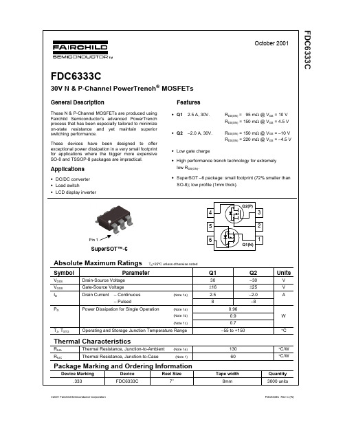
________________General DescriptionThe MAX3222/MAX3232/MAX3237/MAX3241 trans-ceivers have a proprietary low-dropout transmitter out-put stage enabling true RS-232 performance from a 3.0V to 5.5V supply with a dual charge pump. The devices require only four small 0.1µF external charge-pump capacitors. The MAX3222, MAX3232, and MAX3241 are guaranteed to run at data rates of 120kbps while maintaining RS-232 output levels. The MAX3237 is guaranteed to run at data rates of 250kbps in the normal operating mode and 1Mbps in the MegaBaud™ operating mode, while maintaining RS-232output levels.The MAX3222/MAX3232 have 2 receivers and 2 drivers. The MAX3222 features a 1µA shutdown mode that reduces power consumption and extends battery life in portable systems. Its receivers remain active in shutdown mode, allowing external devices such as modems to be monitored using only 1µA supply cur-rent. The MAX3222 and MAX3232 are pin, package,and functionally compatible with the industry-standard MAX242 and MAX232, respectively.The MAX3241 is a complete serial port (3 drivers/5 receivers) designed for notebook and subnotebook computers. The MAX3237 (5 drivers/3 receivers) is ideal for fast modem applications. Both these devices feature a shutdown mode in which all receivers can remain active while using only 1µA supply current. Receivers R1(MAX3237/MAX3241) and R2 (MAX3241) have extra out-puts in addition to their standard outputs. These extra outputs are always active, allowing external devices such as a modem to be monitored without forward bias-ing the protection diodes in circuitry that may have V CC completely removed.The MAX3222, MAX3237, and MAX3241 are available in space-saving TSSOP and SSOP packages.________________________ApplicationsNotebook, Subnotebook, and Palmtop Computers High-Speed ModemsHand-Held Equipment Peripherals Printers3.0V to 5.5V , Low-Power , up to 1Mbps, T rue RS-232Transceivers Using Four 0.1µF External CapacitorsMegaBaud and UCSP are trademarks of Maxim Integrated Products, Inc.Typical Operating Circuits appear at end of data sheet.MAX3222/MAX3232/ MAX3237/MAX3241捷多邦,您值得信赖的PCB打样专家!3.0V to 5.5V , Low-Power , up to 1Mbps, T rue RS-232Transceivers Using Four 0.1µF External CapacitorsABSOLUTE MAXIMUM RATINGSELECTRICAL CHARACTERISTICS(V CC = +3.0V to +5.5V, C1–C4 = 0.1µF (Note 2), T A = T MIN to T MAX , unless otherwise noted. Typical values are at T A = +25°C.)Stresses beyond those listed under “Absolute Maximum Ratings” may cause permanent damage to the device. These are stress ratings only, and functional operation of the device at these or any other conditions beyond those indicated in the operational sections of the specifications is not implied. Exposure to absolute maximum rating conditions for extended periods may affect device reliability.Note 1:V+ and V- can have a maximum magnitude of 7V, but their absolute difference cannot exceed 13V.V CC ...........................................................................-0.3V to +6V V+ (Note 1)...............................................................-0.3V to +7V V- (Note 1)................................................................+0.3V to -7V V+ + V- (Note 1)...................................................................+13V Input VoltagesT_IN, SHDN , EN ...................................................-0.3V to +6V MBAUD...................................................-0.3V to (V CC + 0.3V)R_IN.................................................................................±25V Output VoltagesT_OUT...........................................................................±13.2V R_OUT....................................................-0.3V to (V CC + 0.3V)Short-Circuit DurationT_OUT....................................................................ContinuousContinuous Power Dissipation (T A = +70°C)16-Pin TSSOP (derate 6.7mW/°C above +70°C).............533mW 16-Pin Narrow SO (derate 8.70mW/°C above +70°C)....696mW 16-Pin Wide SO (derate 9.52mW/°C above +70°C)........762mW 16-Pin Plastic DIP (derate 10.53mW/°C above +70°C)...842mW 18-Pin SO (derate 9.52mW/°C above +70°C)..............762mW 18-Pin Plastic DIP (derate 11.11mW/°C above +70°C)..889mW 20-Pin SSOP (derate 7.00mW/°C above +70°C).........559mW 20-Pin TSSOP (derate 8.0mW/°C above +70°C).............640mW 28-Pin TSSOP (derate 8.7mW/°C above +70°C).............696mW 28-Pin SSOP (derate 9.52mW/°C above +70°C).........762mW 28-Pin SO (derate 12.50mW/°C above +70°C).....................1W Operating Temperature RangesMAX32_ _C_ _.....................................................0°C to +70°C MAX32_ _E_ _ .................................................-40°C to +85°C Storage Temperature Range.............................-65°C to +150°C Lead Temperature (soldering, 10s).................................+300°CMAX3222/MAX3232/MAX3237/MAX32413.0V to 5.5V , Low-Power , up to 1Mbps, T rue RS-232Transceivers Using Four 0.1µF External CapacitorsTIMING CHARACTERISTICS—MAX3222/MAX3232/MAX3241(V CC = +3.0V to +5.5V, C1–C4 = 0.1µF (Note 2), T A = T MIN to T MAX , unless otherwise noted. Typical values are at T A = +25°C.)ELECTRICAL CHARACTERISTICS (continued)(V CC = +3.0V to +5.5V, C1–C4 = 0.1µF (Note 2), T A = T MIN to T MAX , unless otherwise noted. Typical values are at T A = +25°C.)MAX3222/MAX3232/MAX3237/MAX32413.0V to 5.5V , Low-Power , up to 1Mbps, T rue RS-232Transceivers Using Four 0.1µF External Capacitors__________________________________________Typical Operating Characteristics(V CC = +3.3V, 235kbps data rate, 0.1µF capacitors, all transmitters loaded with 3k Ω, T A = +25°C, unless otherwise noted.)-6-5-4-3-2-101234560MAX3222/MAX3232TRANSMITTER OUTPUT VOLTAGEvs. LOAD CAPACITANCELOAD CAPACITANCE (pF)T R A N S M I T T E R O U T P U T V O L T A G E (V )20003000100040005000246810121416182022150MAX3222/MAX3232SLEW RATEvs. LOAD CAPACITANCELOAD CAPACITANCE (pF)S L E W R A T E (V /µs )20003000100040005000510152025303540MAX3222/MAX3232SUPPLY CURRENT vs. LOAD CAPACITANCEWHEN TRANSMITTING DATALOAD CAPACITANCE (pF)S U P P L Y C U R R E N T (m A )20003000100040005000TIMING CHARACTERISTICS—MAX3237(V CC = +3.0V to +5.5V, C1–C4 = 0.1µF (Note 2), T A = T MIN to T MAX , unless otherwise noted. Typical values are at T A = +25°C.)Note 2:MAX3222/MAX3232/MAX3241: C1–C4 = 0.1µF tested at 3.3V ±10%; C1 = 0.047µF, C2–C4 = 0.33µF tested at 5.0V ±10%.MAX3237: C1–C4 = 0.1µF tested at 3.3V ±5%; C1–C4 = 0.22µF tested at 3.3V ±10%; C1 = 0.047µF, C2–C4 = 0.33µF tested at 5.0V ±10%.Note 3:Transmitter input hysteresis is typically 250mV.MAX3222/MAX3232/MAX3237/MAX32413.0V to 5.5V , Low-Power , up to 1Mbps, T rue RS-232Transceivers Using Four 0.1µF External Capacitors-7.5-5.0-2.502.55.07.50MAX3241TRANSMITTER OUTPUT VOLTAGEvs. LOAD CAPACITANCELOAD CAPACITANCE (pF)T R A N S M I T T E R O U T P U T V O L T A G E (V )2000300010004000500046810121416182022240MAX3241SLEW RATEvs. LOAD CAPACITANCELOAD CAPACITANCE (pF)S L E W R A T E (V /µs )20003000100040005000510152025303545400MAX3241SUPPLY CURRENT vs. LOADCAPACITANCE WHEN TRANSMITTING DATALOAD CAPACITANCE (pF)S U P P L Y C U R R E N T (m A )20003000100040005000-7.5-5.0-2.502.55.07.50MAX3237TRANSMITTER OUTPUT VOLTAGE vs. LOAD CAPACITANCE (MBAUD = GND)LOAD CAPACITANCE (pF)T R A N S M I T T E R O U T P U T V O L T A G E (V )200030001000400050000102030504060700MAX3237SLEW RATE vs. LOAD CAPACITANCE(MBAUD = V CC )LOAD CAPACITANCE (pF)S L E W R A T E (V /µs )500100015002000-7.5-5.0-2.502.55.07.50MAX3237TRANSMITTER OUTPUT VOLTAGE vs. LOAD CAPACITANCE (MBAUD = V CC )LOAD CAPACITANCE (pF)T R A N S M I T T E R O U T P U T V O L T A G E (V )5001000150020001020304050600MAX3237SUPPLY CURRENT vs.LOAD CAPACITANCE (MBAUD = GND)LOAD CAPACITANCE (pF)S U P P L Y C U R R E N T(m A )200030001000400050000246810120MAX3237SLEW RATE vs. LOAD CAPACITANCE(MBAUD = GND)LOAD CAPACITANCE (pF)S L E W R A T E (V /µs )2000300010004000500010302040506070MAX3237SKEW vs. LOAD CAPACITANCE(t PLH - t PHL )LOAD CAPACITANCE (pF)1000150050020002500_____________________________Typical Operating Characteristics (continued)(V CC = +3.3V, 235kbps data rate, 0.1µF capacitors, all transmitters loaded with 3k Ω, T A = +25°C, unless otherwise noted.)MAX3222/MAX3232/MAX3237/MAX32413.0V to 5.5V , Low-Power , up to 1Mbps, T rue RS-232Transceivers Using Four 0.1µF External Capacitors______________________________________________________________Pin DescriptionMAX3222/MAX3232/MAX3237/MAX32413.0V to 5.5V , Low-Power , up to 1Mbps, T rue RS-232Transceivers Using Four 0.1µF External Capacitors_______________Detailed DescriptionDual Charge-Pump Voltage ConverterThe MAX3222/MAX3232/MAX3237/MAX3241’s internal power supply consists of a regulated dual charge pump that provides output voltages of +5.5V (doubling charge pump) and -5.5V (inverting charge pump), regardless of the input voltage (V CC ) over the 3.0V to 5.5V range. The charge pumps operate in a discontinuous mode; if the output voltages are less than 5.5V, the charge pumps are enabled, and if the output voltages exceed 5.5V, the charge pumps are disabled. Each charge pump requires a flying capacitor (C1, C2) and a reservoir capacitor (C3, C4) to generate the V+ and V- supplies.RS-232 TransmittersThe transmitters are inverting level translators that con-vert CMOS-logic levels to 5.0V EIA/TIA-232 levels.The MAX3222/MAX3232/MAX3241 transmitters guaran-tee a 120kbps data rate with worst-case loads of 3k Ωin parallel with 1000pF, providing compatibility with PC-to-PC communication software (such as LapLink™).Typically, these three devices can operate at data rates of 235kbps. Transmitters can be paralleled to drive multi-ple receivers or mice.The MAX3222/MAX3237/MAX3241’s output stage is turned off (high impedance) when the device is in shut-down mode. When the power is off, the MAX3222/MAX3232/MAX3237/MAX3241 permit the outputs to be driven up to ±12V.The transmitter inputs do not have pullup resistors.Connect unused inputs to GND or V CC .MAX3237 MegaBaud OperationIn normal operating mode (MBAUD = GND ), the MAX3237 transmitters guarantee a 250kbps data rate with worst-case loads of 3k Ωin parallel with 1000pF.This provides compatibility with PC-to-PC communica-tion software, such as Laplink.For higher speed serial communications, the MAX3237features MegaBaud operation. In MegaBaud operating mode (MBAUD = V CC ), the MAX3237 transmitters guar-antee a 1Mbps data rate with worst-case loads of 3k Ωin parallel with 250pF for 3.0V < V CC < 4.5V. For 5V ±10%operation, the MAX3237 transmitters guarantee a 1Mbps data rate into worst-case loads of 3k Ωin parallel with 1000pF.Figure 1. Slew-Rate Test CircuitsLapLink is a trademark of Traveling Software, Inc.MAX3222/MAX3232/MAX3237/MAX32413.0V to 5.5V , Low-Power , up to 1Mbps, T rue RS-232Transceivers Using Four 0.1µF External CapacitorsRS-232 ReceiversThe receivers convert RS-232 signals to CMOS-logic out-put levels. The MAX3222/MAX3237/MAX3241 receivers have inverting three-state outputs. In shutdown, the receivers can be active or inactive (Table 1).The complementary outputs on the MAX3237 (R1OUTB)and the MAX3241 (R1OUTB, R2OUTB) are always active,regardless of the state of EN or SHDN . This allows for Ring Indicator applications without forward biasing other devices connected to the receiver outputs. This is ideal for systems where V CC is set to 0V in shutdown to accommodate peripherals, such as UARTs (Figure 2).MAX3222/MAX3237/MAX3241Shutdown ModeSupply current falls to less than 1µA in shutdown mode (SHDN = low). When shut down, the device’s charge pumps are turned off, V+ is pulled down to V CC , V- is pulled to ground, and the transmitter outputs are dis-abled (high impedance). The time required to exit shut-down is typically 100µs, as shown in Figure 3. Connect SHDN to V CC if the shutdown mode is not used. SHDN has no effect on R_OUT or R_OUTB.MAX3222/MAX3237/MAX3241Enable ControlThe inverting receiver outputs (R_OUT) are put into a high-impedance state when EN is high. The complemen-tary outputs R1OUTB and R2OUTB are always active,regardless of the state of EN and SHDN (Table 1). EN has no effect on T_OUT.__________Applications InformationCapacitor SelectionThe capacitor type used for C1–C4 is not critical for proper operation; polarized or nonpolarized capacitors can be used. The charge pump requires 0.1µF capaci-tors for 3.3V operation. For other supply voltages, refer to Table 2 for required capacitor values. Do not use values lower than those listed in Table 2. Increasing the capaci-tor values (e.g., by a factor of 2) reduces ripple on the transmitter outputs and slightly reduces power consump-tion. C2, C3, and C4 can be increased without changing C1’s value. However, do not increase C1 without also increasing the values of C2, C3, and C4, to maintain the proper ratios (C1 to the other capacitors).When using the minimum required capacitor values,make sure the capacitor value does not degrade exces-sively with temperature. If in doubt, use capacitors with a higher nominal value. The capacitor’s equivalent series resistance (ESR), which usually rises at low tempera-tures, influences the amount of ripple on V+ and V-.Figure 2. Detection of RS-232 Activity when the UART and Interface are Shut Down; Comparison of MAX3237/MAX3241(b) with Previous Transceivers (a).MAX3222/MAX3232/MAX3237/MAX32413.0V to 5.5V , Low-Power , up to 1Mbps, T rue RS-232Transceivers Using Four 0.1µF External CapacitorsPower-Supply DecouplingIn most circumstances, a 0.1µF bypass capacitor is adequate. In applications that are sensitive to power-supply noise, decouple V CC to ground with a capacitor of the same value as charge-pump capacitor C1. Connect bypass capacitors as close to the IC as possible.Operation Down to 2.7VTransmitter outputs will meet EIA/TIA-562 levels of ±3.7V with supply voltages as low as 2.7V.Transmitter Outputs whenExiting ShutdownFigure 3 shows two transmitter outputs when exiting shutdown mode. As they become active, the two trans-mitter outputs are shown going to opposite RS-232 lev-els (one transmitter input is high, the other is low).Each transmitter is loaded with 3k Ωin parallel with 2500pF. The transmitter outputs display no ringing or undesirable transients as they come out of shutdown.Note that the transmitters are enabled only when the magnitude of V- exceeds approximately 3V.Mouse DriveabilityThe MAX3241 has been specifically designed to power serial mice while operating from low-voltage power sup-plies. It has been tested with leading mouse brands from manufacturers such as Microsoft and Logitech. The MAX3241 successfully drove all serial mice tested and met their respective current and voltage requirements.Figure 4a shows the transmitter output voltages under increasing load current at 3.0V. Figure 4b shows a typical mouse connection using the MAX3241.CC = 3.3V C1–C4 = 0.1µF50µs/divFigure 3. Transmitter Outputs when Exiting Shutdown or Powering UpMAX3222/MAX3232/MAX3237/MAX32413.0V to 5.5V , Low-Power , up to 1Mbps, T rue RS-232Transceivers Using Four 0.1µF External CapacitorsFigure 4b. Mouse Driver Test CircuitFigure 4a. MAX3241 Transmitter Output Voltage vs. Load Current per TransmitterMAX3222/MAX3232/MAX3237/MAX32413.0V to 5.5V, Low-Power, up to 1Mbps, T rue RS-232Transceivers Using Four 0.1µF External CapacitorsHigh Data RatesThe MAX3222/MAX3232/MAX3241 maintain the RS-232±5.0V minimum transmitter output voltage even at highdata rates. Figure 5 shows a transmitter loopback testcircuit. Figure 6 shows a loopback test result at120kbps, and Figure 7 shows the same test at 235kbps.For Figure 6, all transmitters were driven simultaneouslyat 120kbps into RS-232 loads in parallel with 1000pF.For Figure 7, a single transmitter was driven at 235kbps,and all transmitters were loaded with an RS-232 receiverin parallel with 1000pF.The MAX3237 maintains the RS-232 ±5.0V minimumtransmitter output voltage at data rates up to 1Mbps.Figure 8 shows a loopback test result at 1Mbps withMBAUD = V CC. For Figure 8, all transmitters wereloaded with an RS-232 receiver in parallel with 250pF.CC = 3.3V5µs/divFigure 5. Loopback Test CircuitFigure 6. MAX3241 Loopback Test Result at 120kbpsCC = 3.3V2µs/divFigure 7. MAX3241 Loopback Test Result at 235kbps0V +5V 0V -5V +5V 0VT_INT_OUT = R_IN5kR_OUT150pF200ns/divCC = 3.3VFigure 8. MAX3237 Loopback Test Result at 1000kbps(MBAUD = V CC)MAX3222/MAX3232/MAX3237/MAX32413.0V to 5.5V , Low-Power , up to 1Mbps, T rue RS-232Transceivers Using Four 0.1µF External Capacitors__________________________________________________Typical Operating CircuitsInterconnection with 3V and 5V LogicThe MAX3222/MAX3232/MAX3237/MAX3241 can directly interface with various 5V logic families, includ-ing ACT and HCT CMOS. See Table 3 for more informa-tion on possible combinations of interconnections.Table 3. Logic-Family Compatibility with Various Supply VoltagesMAX3222/MAX3232/MAX3237/MAX3241MAX3222/MAX3232/MAX3237/MAX3241 3.0V to 5.5V, Low-Power, up to 1Mbps, T rue RS-232Transceivers Using Four 0.1µF External Capacitors_____________________________________Typical Operating Circuits (continued)MAX3222/MAX3232/MAX3237/MAX32413.0V to 5.5V, Low-Power, up to 1Mbps, T rue RS-232 Transceivers Using Four 0.1µF External Capacitors_____________________________________________Pin Configurations (continued)3.0V to 5.5V , Low-Power , up to 1Mbps, T rue RS-232Transceivers Using Four 0.1µF External Capacitors______3V-Powered EIA/TIA-232 and EIA/TIA-562 Transceivers from MaximOrdering Information (continued)*Dice are tested at T A = +25°C, DC parameters only.+Denotes lead-free package.MAX3222/MAX3232/MAX3237/MAX32413.0V to 5.5V , Low-Power , up to 1Mbps, T rue RS-232Transceivers Using Four 0.1µF External Capacitors___________________Chip Topography___________________Chip InformationT1INT2IN 0.127"(3.225mm)0.087"(2.209mm)R2OUTR2IN T2OUTV CCV+C1+SHDNENC1- C2+C2-V-MAX3222TRANSISTOR COUNT: 339SUBSTRATE CONNECTED TO GNDMAX3222/MAX3232/MAX3237/MAX32413.0V to 5.5V , Low-Power , up to 1Mbps, T rue RS-232Transceivers Using Four 0.1µF External CapacitorsPackage Information(The package drawing(s) in this data sheet may not reflect the most current specifications. For the latest package outline information,go to /packages .)Revision HistoryPages changed at Rev 7: 1, 15, 16, 17MAX3222/MAX3232/MAX3237/MAX3241Maxim Integrated 160 Rio Robles, San Jose, CA 95134 USA 1-408-601-1000Maxim cannot assume responsibility for use of any circuitry other than circuitry entirely embodied in a Maxim product. No circuit patent licenses are implied. Maxim reserves the right to change the circuitry and specifications without notice at any time. The parametric values (min and max limits) shown in the Electrical Characteristics table are guaranteed. Other parametric values quoted in this data sheet are provided for guidance.©2007 Maxim IntegratedThe Maxim logo and Maxim Integrated are trademarks of Maxim Integrated Products, Inc.。


描述MP24833 是 55V,3A白光 LED 驱动器适用于降压,反相升/降压和升压应用。
它具有 3A输出电流在较宽的输入电压范围内具有优异的负载和线性调整。
电流模式能提供快速的瞬态响应和环路稳定性设计。
故障保护包括热关断,逐周期峰值电流限制,开弦保护和输出短路保护。
MP24833 采用模拟和PWM调光复用一个控制引脚。
单独的输入参考接地引脚可以直接使能芯片或者调光控制为正的负功率转换。
MP24833需要最少的标准外部元件和采用SOIC8E 封装。
特点•3A 最大输出电流•独特的升降压操作 (降压-升压模式)•宽输入电压范围:4.5V~55V(降压模式)•0.19Ω 内部功率MOSFET开关•开关频率:200KHz•模拟和PWM调光•0.198V 参考电压•6μA 关断模式•无LED最小数量•稳定低ESR陶瓷输出电容器•逐周期过流保护•热关断保护•开弦保护•输出短路保护•封装: SOIC8E应用•常规 LED 照明•LCD背光板•笔记本电脑•汽车内部照明•便携式多媒体播放器•便携式 GPS 设备For MPS green status, please visit MPS website under Quality Assurance.“MPS” and “The Future of Analog IC Technology” are Registered Trademarks of Monolithic Power Systems, Inc.MP24833A, 55V3白光LED驱动器The Future of Analog IC Technology绝对最大额定值 (1)供应电压 V DD - V SS .............................................. 60V V SW - V SS ......................................-0.3V to V IN + 0.3V V BST .............................................................V SW + 6V V EN/Dim - V INGND ..........................................-0.3Vto+6V V INGND - V SS ............................................-0.3V to 60V 其他引脚 - V SS ….....................................-0.3V to +6V 连续功率耗散(T A= +25°C) (2)SOIC8E..............................................................2.5W 结温……………………....................................150°C 铅温度………………….....................................260°C 贮存温度……………..................-65°C to +150°C推荐的操作条件 (3)供应电压 V DD - V SS ..................................4.5V to 55VJ C热阻 (4) θJA θJCSOIC-8 EP ..............................50 ......10...°C/W备注:1) 超过绝对最大额定值可能会损坏芯片.2) 最大允许功率耗散是一个函数的最大结温T J (MAX), 结到环境热阻 θJA , 和 环境温度 T A . 在任何环境温度的最大允许连续功率耗散计算由P D (MAX) = (T J (MAX)-T A )/θJA . 超过最大允许功耗 会导致过高的模具温度, 同时芯片将进入热关断.对内部热关断电路造成永久性的损坏.3) 芯片不能保证在推荐的工作条件以外的情况下正常工作. 4) 测试是在 JESD51-7, 4-layer PCB.定购信息引脚配置4.5V V IN 55V5) 保证所设计的.典型性能特征性能波形测试在评估板的设计示例部分. V IN = 36V, I LED = 1A, 7个WLEDs 串联, L = 68µH, T A = 25°C, 降压应用,除非另有说明.典型的性能特征(续)性能波形测试在评估板的设计示例部分. V IN = 24V, I LED = 1A, 7个WLEDs 串联, L = 68µH, T A = 25°C, 降压升压应用, 考阅 INGND, 除非另有说明.引脚功能功能方框图图1: 功能框图操作MP24833是一个电流型调节器,误差放大器 (EA) 的输出电压与峰值电感电流成正比。


__________________________________________Typical Operating Characteristics(V CC = +3.3V, 235kbps data rate, 0.1µF capacitors, all transmitters loaded with 3k Ω, T A = +25°C, unless otherwise noted.)TIMING CHARACTERISTICS—MAX3237(V CC = +3.0V to +5.5V, C1–C4 = 0.1µF (Note 2), T A = T MIN to T MAX , unless otherwise noted. Typical values are at T A = +25°C.)Note 2:MAX3222/MAX3232/MAX3241: C1–C4 = 0.1µF tested at 3.3V ±10%; C1 = 0.047µF, C2–C4 = 0.33µF tested at 5.0V ±10%.MAX3237: C1–C4 = 0.1µF tested at 3.3V ±5%; C1–C4 = 0.22µF tested at 3.3V ±10%; C1 = 0.047µF, C2–C4 = 0.33µF tested at 5.0V ±10%.Note 3:Transmitter input hysteresis is typically 250mV.-6-5-4-3-2-101234560MAX3222/MAX3232TRANSMITTER OUTPUT VOLTAGEvs. LOAD CAPACITANCELOAD CAPACITANCE (pF)T R A N S M I T T E R O U T P U T V O L T A G E (V )20003000100040005000246810121416182022150MAX3222/MAX3232SLEW RATEvs. LOAD CAPACITANCELOAD CAPACITANCE (pF)S L E W R A T E (V /μs )20003000100040005000510152025303540MAX3222/MAX3232SUPPLY CURRENT vs. LOAD CAPACITANCEWHEN TRANSMITTING DATALOAD CAPACITANCE (pF)S U P P L Y C U R R E N T (m A )20003000100040005000MAX3222/MAX3232/MAX3237/MAX32413.0V to 5.5V, Low-Power, up to 1Mbps, True RS-232 Transceivers Using Four 0.1µF External CapacitorsFigure 4a. MAX3241 Transmitter Output Voltage vs. Load Current per Transmitter3.0V to 5.5V , Low-Power, up to 1Mbps, True RS-232Transceivers Using Four 0.1µF External CapacitorsMAX3222/MAX3232/MAX3237/MAX3241CC = 3.3V5μs/divFigure 5. Loopback Test CircuitHigh Data RatesThe MAX3222/MAX3232/MAX3241 maintain the RS-232±5.0V minimum transmitter output voltage even at high data rates. Figure 5 shows a transmitter loopb ack test circuit. Figure 6 shows a loopb ack test result at 120kbps, and Figure 7 shows the same test at 235kbps. For Figure 6, all transmitters were driven simultaneously at 120kb ps into RS-232 loads in parallel with 1000pF. For Figure 7, a single transmitter was driven at 235kbps, and all transmitters were loaded with an RS-232 receiver in parallel with 1000pF.The MAX3237 maintains the RS-232 ±5.0V minimum transmitter output voltage at data rates up to 1Mb ps. Figure 8 shows a loopb ack test result at 1Mb ps with MBAUD = V CC . For Figure 8, all transmitters were loaded with an RS-232 receiver in parallel with 250pF.fdzfdfbbFigure 6. MAX3241 Loopback Test Result at 120kbpsCC = 3.3V2μs/divFigure 7. MAX3241 Loopback Test Result at 235kbps0V +5V 0V -5V +5V 0VT_INT_OUT = R_IN 5k R_OUT 150pF200ns/divCC = 3.3VFigure 8. MAX3237 Loopback Test Result at 1000kbps (MBAUD = V CC )___________________Chip Topography___________________Chip InformationT1INT2IN 0.087"(2.209mm)R2OUTR2IN T2OUT R1OUTR1INT1OUTV CCV+C1+ENC1-C2+C2-V-GNDTRANSISTOR COUNT: 339SUBSTRATE CONNECTED TO GNDMAX3222/MAX3232/MAX3237/MAX3241 3.0V to 5.5V, Low-Power, up to 1Mbps, True RS-232Transceivers Using Four 0.1µF External Capacitors。

三极管知识简介概述半导体三极管也称为晶体三极管,可以说它是电子电路中最重要的器件。
它最主要的功能是电流放大和开关作用。
三极管顾名思义具有三个电极。
二极管是由一个PN结构成的,而三极管由两个PN结构成,共用的一个电极成为三极管的基极(用字母b表示)。
其他的两个电极成为集电极(用字母c表示)和发射极(用字母e表示)。
由于不同的组合方式,形成了一种是NPN型的三极管,另一种是PNP型的三极管。
三极管的种类很多,并且不同型号各有不同的用途。
三极管大都是塑料封装或金属封装,常见三极管的外观,有一个箭头的电极是发射极,箭头朝外的是NPN型三极管,而箭头朝内的是PNP型。
实际上箭头所指的方向是电流的方向。
电子制作中常用的三极管有90××系列,包括低频小功率硅管9013(NPN)、9012(PNP),低噪声管9014(NPN),高频小功率管9018(NPN)等。
它们的型号一般都标在塑壳上,而样子都一样,都是TO-92标准封装。
在老式的电子产品中还能见到3DG6(低频小功率硅管)、3AX31(低频小功率锗管)等,它们的型号也都印在金属的外壳上。
我国生产的晶体管有一套命名规则,电子工程技术人员和电子爱好者应该了解三极管符号的含义。
符号的第一部分“3”表示三极管。
符号的第二部分表示器件的材料和结构:A——PNP型锗材料;B——NPN型锗材料;C——PNP型硅材料;D——NPN型硅材料。
符号的第三部分表示功能:U——光电管;K——开关管;X——低频小功率管;G——高频小功率管;D——低频大功率管;A——高频大功率管。
另外,3DJ型为场效应管,BT打头的表示半导体特殊元件。
三极管最基本的作用是放大作用,它可以把微弱的电信号变成一定强度的信号,当然这种转换仍然遵循能量守恒,它只是把电源的能量转换成信号的能量罢了。
三极管有一个重要参数就是电流放大系数 b。
当三极管的基极上加一个微小的电流时,在集电极上可以得到一个是注入电流b 倍的电流,即集电极电流。


Quad SP6330-SP6332- SP6334 Quad Power Supervisory Circuit Family is a family of microprocessor reset supervisory circuits with multiple reset voltages. The family provides low voltage monitoring ability for up-to four supplies with two precision factory-set thresholds and two user defined custom thresholds. These circuits perform a single function: if any of the input supply voltages drops below its associated threshold, reset outputs are asserted. The SP6330, SP6332, and SP6334 are packaged in an 8-pin TSOT package. All devices are fully specified over -40o C to +85o C temperature range.50ms, 100ms, 200ms and 400ms ■ Watch Dog Input Functionality -- WDI ■ Manual Reset Input (Active Low) -- MRIB ■ 8 Pin TSOT packageDESCRIPTIONAvailable in Lead Free PackagingAVAILABLE PINOUTSTYPICAL APPLICATION CIRCUITTerminal Voltage (with respect to GND)V1, V2..................................................... -0.3 to +6V Open-Drain RSTB .......................................-0.3 to +6V CMOS RST, RSTB, ..................... -0.3 to (V1+0.3V) Input Current/OutputCurrent..................................,,........................20mA V3, V4, MRIB, WDI ........................-0.3 to (V1+0.3V)ABSOLUTE MAXIMUM RATINGSOperating TemperatureRange ...............................................-40°C to +85 °C Storage TemperatureRange...............................................-65°C to 150°C Thermal Resistance O JA .............................134°C/WThese are stress ratings only and functional operation of the device at these ratings or any other above those indicated in the operation sections of the specifications below is not implied. Exposure to absolute maximum rating conditions for extended periods of time may affect reliability and cause permanent damage to the device.Representative Samples AvailableELECTRICAL CHARACTERISTICSPIN DESCRIPTIONThe SP6330, SP6332, and SP6334 include a low-voltage precision bandgap reference, four precision comparators, an oscillator, a digital counter chain, a logic control block, trimmed resistor divider chains and additional supporting circuitry. The family is designed to supervise up to 4 independent supply voltages. V1 and V2 supply inputs have their resistor dividers on the chip. Their trip thresholds are factory trimmed. V3 and V4 inputs allow user to customizeBlock Diagramtwo additional supply thresholds to be monitored by means of external resistor dividers. The devices also feature manual reset and watchdog functionalities.As these devices do not have watchdog outputs, the watchdog timer is serviced internally during the watchdog timeout period when WDI is left unconnected. The watchdog functionality can be disabled by leaving the WDI input floating.RSTB (RST)GND MRIBFigure 1: Functionality of a SP63XX family member with manual reset and watchdog capabilities but without WDOB output.• V1 > Vth1, V2 > Vth2 , V3 > Vth3 and V4 > Vth4 (all supplies over their corresponding thresholds)---> RSTB is de-asserted after reset timeout period (Trp).• MRIB goes to “LOW” to force “Reset” ----> RSTB is asserted immediately.• WDI does not make any transition during watchdog timeout period (Twd) ---->RSTB is asserted for a duration of reset timeout period (Trp).• One of the supplies drops below its corresponding threshold (in this case V3)---->RSTB is asserted immediately.V1V2V3V4MRIB WDIV1RSTBResetB Timeout DelayWatchdog Timeout Period10020030040050085 80 70 60 50 40 30 20 10 0 -10 -20 -30 -40D e g CRe s e t T i m e o u t ( m S e c )Reset Timeout vs. TemperatureResetTimeout Delay Vs. TemperatureReset Good(400ms Reset)V1 and V2 Glitch RejectionV3 and V4 Glitch RejectionPACKAGE: 8 PIN TSOTPart Naming NomenclatureSP63NN - Th1 - Th2 - TOPT33 -- Quad Sp, CMOS RSTB34 -- Quad Sp, MR, WDI, CMOS RST35 -- Quad Sp, CMOS RST36 -- Triple Sp, WDI, PF, OD RSTB37 -- Triple Sp, WDI, PF, CMOS RSTB38 -- Triple Sp, WDI, PF, CMOS RST39 -- Triple Sp, MR, WDI, OD RSTB - WDOB40 -- Dual Sp, WDI, OD RSTB - WDOB41 -- Triple Sp, WDI, PF, CMOS RSTB - WDOB42 -- Dual Sp, WDI, CMOS RSTB - WDOBIJKLMModelTemperature RangePackage TypesSP6330EK1-L-X-X-X...........................................-40°C to +85°C.................................Lead Free 8-Pin TSOT SP6330EK1-L-X-X-X/TR......................................-40°C to +85°C.................................Lead Free 8-Pin TSOT SP6332EK1-L-X-X-X............................................-40°C to +85°C.................................Lead Free 8-Pin TSOT SP6332EK1-L-X-X-X/TR......................................-40°C to +85°C.................................Lead Free 8-Pi n TSOT SP6334EK1-L-X-X-X............................................-40°C to +85°C.................................Lead Free 8-Pin TSOT SP6334EK1-L-X-X-X/TR......................................-40°C to +85°C.................................Lead Free 8-Pi n TSOT Available in lead free packaging only. /TR = Tape and Reel Pack quantity 2,500 forTSOT-8Contact Factory for availability of particular voltage threshold and reset timeout options. Note that the Ordering Information denoting those options corresponds to the Part Naming Nomenclature shown on the previous page.Ordering example: SP6330EK1-L-W-G-C/TR == W -- 2.925V for Voltage Threshold 1; G -- 1.575V for Voltage Threshold 2; and C -- 200ms reset timeout.ORDERING INFORMATIONSipex Corporation Headquarters and Sales Office233 South Hillview Drive Milpitas, CA 95035 TEL: (408) 934-7500 FAX: (408) 935-7600Sipex Corporation reserves the right to make changes to any products described herein. Sipex does not assume any liability arising out of the application or use of any product or circuit described herein; neither does it convey any license under its patent rights nor the rights of others.。

接线图8引脚塑料DIP (N )包装"~.特点 四象限乘法 低成本8引脚封装 完整的,无需外部元件 激光微调精度和稳定性 总误差在满量程的2% 差分高阻抗X 和Y 输入 高阻抗单位增益求和输入 激光微调10伏标定参考值 应用 ! 乘法,除法,磨边调制/解调,相位检测 压控放大器/衰减器/过滤器 产品说明 该AD633是一个功能完整的四象限模拟乘法器。
它包括高阻抗,差动X 和Y 输入和一个高阻抗求和输入(Z 轴)。
低阻抗输出电压是由一个嵌入式齐纳二极管提供了一个标称10 V 全面。
该AD633是提供在价格适中的8引脚塑料DIP 和SOIC 封装这些功能的第一款产品。
该AD633是激光校准,满量程的2%保证总精度。
非线性度为Y 输入通常小于%,并提到了输出噪声通常在10 Hz至10 kHz 的带宽小于100μVRMS 。
1 MHz 带宽,20 V/μs 压摆率,并且驱动容性负载的能力,使AD633有用在各种各样的应用中,简单性和成本是关键问题。
"该AD633的通用性不是由它的简单性大打折扣。
其Z 输入提供对输出缓冲放大器,使用户能够总结的两个或更多个乘法器的输出,增加乘法器的增益,其输出电压转换为电流,并配置各种应用。
该AD633是在一个8引脚塑料DIP 封装(N )和8引脚SOIC (R )。
它被指定为工作在0°C 至+70°C 商业级温度范围(十级)或-40°C 至+85°C 工业级温度范围(A 级)。
8引脚塑料SOIC (SO-8)封装 产品亮点1,AD633是在提供了一个完整的四象限乘法器 低成本的8引脚塑料封装。
其结果是一种产品,是成本效益和易于应用。
2,无需外部元件或昂贵的用户校准是 以应用AD633必需的。
3,整体建设和激光校准使脱 副稳定可靠。
4,高(10M Ω)输入电阻使信号源负载可以忽略不计。
5,电源电压范围可以从± V 至±18 V 的 /内部标定电压是由一个稳定的齐纳二极管产生的;乘法器精度基本上是供应不区分大小写。

PC-6333 多功能模入模出接口卡技术说明书1.概述:PC-6333 多功能模入模出接口卡适用于具有ISA 总线的PC系列微机,具有很好的兼容性,CPU从目前广泛使用的64位处理器直到早期的16位处理器均可适用,操作系统可选用经典的MS-DOS,目前流行的 Windows 系列,高稳定性的Unix等多种操作系统以及专业数据采集分析系统 LabVIEW 等软件环境。
在硬件的安装上也非常简单,使用时只需将接口卡插入机内任何一个ISA总线插槽中,信号电缆从机箱外部直接接入。
也可插入我所研制的PC 扩展箱内使用。
本卡可广泛应用于工业过程控制系统以及实验室数据采集系统。
PC-6333 多功能模入模出接口卡安装使用方便,程序编制简单。
其模入模出及I/O信号均由卡上的37芯D 型插头与外部信号源及设备连接。
对于模入部分,用户可根据实际需要选择单端或双端输入方式。
对于模出部分,用户可根据控制对象的需要选择电压或电流输出方式以及不同的量程。
本卡上的A/D、D/A 转换均为12位,同时还备有6路数字量输入和6 路数字量输出接口,三路16位字长的计数/定时器,以及1Mhz 的基准时钟。
本卡的A/D 转换启动方式可以选用程序触发、定时器自动触发、外同步触发等方式,转换状态可以用程序查询,也可以用中断方式通知CPU读取转换结果。
2. 主要技术参数:2.1 模入部分:2.1.1 输入通道数:单端16路;* ( 标*为出厂标准状态,下同 )双端8路2.1.2 输入信号范围:0V~10V*;-5V~+5V2.1.3 输入阻抗:≥ 10MΩ2.1.4 A/D转换分辨率:12位2.1.5 A/D转换速度:10μS2.1.6 A/D启动方式:程序启动/定时触发启动/外触发启动2.1.7 A/D转换结束识别:程序查询/中断方式2.1.8 A/D转换非线性误差:±1LSB2.1.9 A/D转换输出码制:单极性原码*/双极性偏移码2.1.10 系统综合误差:≤ 0.1% F.S2.2 模出部分:2.2.1 输出通道数:1路2.2.2 输出范围:电压方式:0~5V;0~10V*;-5V~+5V;-2.5V~+2.5V电流方式:0~10mA;4~20mA2.2.3 输出阻抗:≤ 2Ω ( 电压方式 )2.2.4 D/A转换器件:DAC12102.2.5 D/A转换分辨率:12位2.2.6 D/A转换输入码制:二进制原码 ( 单极性输出方式时 ) *二进制偏移码 ( 双极性电压输出方式时 )2.2.7 D/A转换综合建立时间:≤ 2μS2.2.8 D/A转换综合误差:电压方式:≤ 0.1% F.S电流方式:≤ 0.5% F.S2.2.9 电压输出方式负载电流:≤ 5mA2.2.10 电流输出方式负载电阻范围:使用机内+12V电源时:0~250Ω外加+24V电源时:0~750Ω2.3 数字量输入输出部分:2.3.1 DI:6路/DO:6路;TTL电平2.3.2 16位字长计数/定时器:3路,用户可外接使用一路计数/定时通道2.3.3 基准时钟:1MHz,占空比50%2.4 电源功耗:+ 5V(±10%) ≤ 500mA+12V(±10%) ≤ 100mA ( D/A 4~20mA输出,并使用机内电源时 )- 5V(±10%) ≤ 10mA-12V(±10%) ≤ 50mA2.5 使用环境要求:工作温度:10℃~40℃相对湿度: 40%~80%存贮温度:-55℃~+85℃2.6 外型尺寸:( 不含档板 )长×高=185.5mm×106.7 mm ( 7.3英寸×4.2英寸 )3. 工作原理:PC-6333模入模出接口卡主要由模数转换电路、数模转换电路、数字量输入输出电路,接口控制逻辑电路构成。

使用说明书USER MANUAL安全注意事项注意∶为防电击,请勿打开机盖(或后盖)。
本机内部无使用者可以维修的部件。
请委托有资格的技术人员进行维修。
注意∶为了完全切断本机的电源,请从墙上插座中拔出插头。
电源插头用于 完全中断机器的电源供应。
本说明书内容如有更新,恕不另行通知.若您使用的产品功能与说明书不一致时,请以产品为准!特点每个细节都是High-End级的设计。
4片美国BB公司传奇的R-2R芯片PCM1704U-J, 每通道2片,全平衡设计, 最大程度发挥芯片性能!顶级数字滤波芯片SM5847。
USB使用XMOS第二代16核处理器XU216, 支持到原生DSD512和32位768kHz!时钟系统使用2颗美国ACCUSILICON超低相噪晶振。
使用AL TERA的高速CPLD对时钟进行处理,降低JITTER。
支持LVDS电平的I2S传输(使用HDMI接口),可以最低JITTER地传输数字音频!内置低时钟抖动VCXO和PLL, 支持接入外部时钟!使用彩色液晶显示屏和新开发的用户界面,全功能遥控。
使用7颗美国TI的OPA1612顶级运放。
大量使用发烧级元器件,高精度、低温漂和电阻和电容。
专门开发的低噪声分立元件电源稳压电路。
由英国Noratel制造的定制低噪声灌封环形变压器。
全铝合金CNC外壳, 电源和主板分仓设计, 有效隔绝电源干扰。
目录安全注意事项 (1)特点 (2)目录 (3)技术参数 (5)关于遥控器 (6)部件介绍......................................................................................7~8主机前面. (7)主机背面 (8)显示界面和操作介绍................................................................9-12恢复出厂设置/保修条款. (13)Table of contentSafety notes (14)Features (15)Specification (16)Remote Control (17)Functions..................................................................................................................................18~19 Main unit front (18)Main unit back (19)Operation Instructions.................................................................................................20-23 Factory Reset/Warranty Terms. (24)技术参数输入方式 B /光纤/同轴/I2S/ AES(EBU) 输出方式 ......................................................................................................单端线路/平衡线路 THD+N ............................................................................................................................0.001% 动态范围 ...........................................................................................................................112dB 信噪比 ..............................................................................................................................112dB USB传输方式 ............................................................................................................... 异步传输 USB兼容性 ...............................................................Windows 7 / 8 / 8.1 / 10, Mac OSX, Linux 位深 B / I2S 1bit,16~32bit 光纤/同轴/AES(EBU) 1bit,16~24bit 采样率 B / I2S PCM 44.1~768kHzDSD 2.8224~22.5792MHz 光纤/同轴/AES(EBU) PCM 44.1~192kHz 消耗功率 ..............................................................................................................................10W 待机功耗 ...........................................................................................................................<0.8W 体积 ...................................................................................................280X240X51mm(WxHxD)重量 ..................................................................................................................................3.96kg如果遥控器距离本机很近时操作仍无效,请用新电池更换。

General DescriptionThe MAX6332/MAX6333/MAX6334 microprocessor (µP)supervisory circuits monitor the power supplies in 1.8V to 3.3V µP and digital systems. They increase circuit reliability and reduce cost by eliminating external com-ponents and adjustments.These devices perform a single function: they assert a reset signal whenever the V CC supply voltage declines below a preset threshold, keeping it asserted for a pre-set timeout period after V CC has risen above the reset threshold. The only difference among the three devices is their output. The MAX6333 (push/pull) and MAX6334(open-drain) have an active-low RESET output, while the MAX6332 (push/pull) has an active-high RESET out-put. The MAX6332/MAX6333 are guaranteed to be in the correct state for V CC down to 0.7V. The MAX6334 is guaranteed to be in the correct state for V CC down to 1.0V.The reset comparator in these ICs is designed to ignore fast transients on V CC . Reset thresholds are factory-trimmable between 1.6V and 2.5V, in approximately 100mV increments. There are 15 standard versions available (2,500 piece minimum-order quantity); con-tact the factory for availability of nonstandard versions (10,000 piece minimum-order quantity). For space-criti-cal applications, the MAX6332/MAX6333/MAX6334come packaged in a 3-pin SOT23.ApplicationsPentium II™ Computers Computers ControllersIntelligent InstrumentsCritical µP/µC Power Monitoring Portable/Battery-Powered Equipment AutomotiveFeatures♦Ultra-Low 0.7V Operating Supply Voltage♦Low 3.3µA Supply Current♦Precision Monitoring of 1.8V and 2.5V Power-Supply Voltages ♦Reset Thresholds Available from 1.6V to 2.5V,in Approximately 100mV Increments ♦Fully Specified over Temperature♦Three Power-On Reset Pulse Widths Available (1ms min, 20ms min, 100ms min)♦Low Cost♦Three Available Output Structures: Push/Pull RESET , Push/Pull RESET, Open-Drain RESET ♦Guaranteed RESET/RESET Valid to V CC = 0.7V (MAX6332/MAX6333)♦Power-Supply Transient Immunity ♦No External Components ♦3-Pin SOT23 Package♦Pin Compatible with MAX809/MAX810 and MAX6326/MAX6327/MAX6328MAX6332/MAX6333/MAX63343-Pin, Ultra-Low-Voltage, Low-PowerµP Reset Circuits________________________________________________________________Maxim Integrated Products119-1411; Rev 2; 12/05Ordering Information* These devices are available in factory-set V CC reset thresh-olds from 1.6V to 2.5V, in approximately 0.1V increments.Choose the desired reset threshold suffix from Table 1 and insert it in the blanks following “UR” in the part number.Factory-programmed reset timeout periods are also available.Insert the number corresponding to the desired nominal reset timeout period (1 = 1ms min, 2 = 20ms min, 3 = 100ms min) in the blank following “D” in the part number. There are 15 stan-dard versions with a required order increment of 2500 pieces.Sample stock is generally held on the standard versions only (see Selector Guide). Contact the factory for availability of non-standard versions (required order increment is 10,000 pieces).All devices available in tape-and-reel only.Devices are available in both leaded and lead-free packaging.Specify lead-free by replacing “-T” with “+T” when ordering.Typical Operating Circuit and Pin Configuration appear at end of data sheet.Selector Guide appears at end of data sheet.Pentium II is a trademark of Intel Corp.For pricing, delivery, and ordering information,please contact Maxim/Dallas Direct!at 1-888-629-4642, or visit Maxim’s website at .M A X 6332/M A X 6333/M A X 63343-Pin, Ultra-Low-Voltage, Low-Power µP Reset Circuits 2_______________________________________________________________________________________ABSOLUTE MAXIMUM RATINGSELECTRICAL CHARACTERISTICS(V CC = full range, T A = -40°C to +125°C, unless otherwise noted. Typical values are at T A = +25°C and V CC = 3V, reset not assert-Stresses beyond those listed under “Absolute Maximum Ratings” may cause permanent damage to the device. These are stress ratings only, and functional operation of the device at these or any other conditions beyond those indicated in the operational sections of the specifications is not implied. Exposure to absolute maximum rating conditions for extended periods may affect device reliability.Terminal Voltage (with respect to GND)V CC ......................................................................-0.3V to +6V Push/Pull RESET, RESET .......................-0.3V to (V CC + 0.3V)Open-Drain RESET ..............................................-0.3V to +6V Input Current (V CC ).............................................................20mA Output Current (RESET, RESET ).........................................20mAContinuous Power Dissipation (T A = +70°C)SOT23-3 (derate 4mW/°C above +70°C)....................320mW Operating Temperature Range .........................-40°C to +125°C Storage Temperature Range.............................-65°C to +160°C Lead Temperature (soldering, 10s).................................+300°C3-Pin, Ultra-Low-Voltage, Low-PowerµP Reset Circuits_______________________________________________________________________________________32.02.62.23.03.63.83.43.24.0-602.4-40-202.820406080100SUPPLY CURRENT vs. TEMPERATURETEMPERATURE (°C)I C C (µA )0.9500.9900.9701.0001.0301.0401.0201.0101.050-60-400.980-2000.96020406080100NORMALIZED RESET TIMEOUT PERIODvs. TEMPERATURETEMPERATURE (°C)N O R M A L I Z E D R E S E T T I M E O U T P E R I O D1020-20403070605080-600-4020406080100V CCFALLING PROPAGATION DELAYvs. TEMPERATURETEMPERATURE (°C)P R O P A G A T I O N D E L A Y (µs )10010001002004003005006000.1110MAXIMUM TRANSIENT DURATION vs. RESET COMPARATOR OVERDRIVERESET COMPARATOR OVERDRIVE (mV)M A X I M U M T R A N S I E N T D U R A T I O N (µs )402080601001201401600.5 1.0 1.250.75 1.5 1.75 2.0 2.25 2.5OUTPUT VOLTAGE HIGH vs. SUPPLY VOLTAGEV CC (V)O U T P U T V O L T A G E H I G H (V C C - V O H ) (m V )20103060705040800.5 1.00 1.50 2.00 2.50 3.00OUTPUT VOLTAGE LOW vs. SUPPLY VOLTAGEV CC (V)O U T P U T V O L T A G E L O W (m V )Typical Operating Characteristics(Reset not asserted, T A = +25°C, unless otherwise noted.)MAX6332/MAX6333/MAX6334Pin DescriptionM A X 6332/M A X 6333/M A X 63343-Pin, Ultra-Low-Voltage, Low-Power µP Reset Circuits 4_____________________________________________________________________________________________________Applications InformationInterfacing to µPs with BidirectionalReset PinsSince the RESET output on the MAX6334 is open-drain,this device interfaces easily with µPs that have bidirec-tional reset pins, such as the Motorola 68HC11.Connecting the µP supervisor’s RESET output directly to the microcontroller’s (µC’s) RESET pin with a single pull-up resistor allows either device to assert reset (Figure 1).Negative-Going V CC TransientsIn addition to issuing a reset to the µP during power-up,power-down, and brownout conditions, these devices are relatively immune to short-duration, negative-going V CC transients (glitches). The Typical Operating Characteristics show the Maximum Transient Duration vs. Reset Comparator Overdrive graph. The graph shows the maxi-mum pulse width that a negative-going V CC transient may typically have without issuing a reset signal. As the ampli-tude of the transient increases, the maximum allowable pulse width decreases.Ensuring a Valid Reset OutputDown to V CC = 0When V CC falls below 1V and approaches the minimum operating voltage of 0.7V, push/pull-structured reset sinking (or sourcing) capabilities decrease drastically.High-impedance CMOS-logic inputs connected to the RESET pin can drift to indeterminate voltages. This does not present a problem in most cases, since most µPs and circuitry do not operate at V CC below 1V. For the MAX6333, where RESET must be valid down to 0,adding a pull-down resistor between RESET and GND removes stray leakage currents, holding RESET low (Figure 2a). The pull-down resistor value is not critical;100k Ωis large enough not to load RESET and small enough to pull it low. For the MAX6332, where RESET must be valid to V CC = 0, a 100k Ωpull-up resistor between RESET and V CC will hold RESET high when V CC falls below 0.7V (Figure 2b).Since the MAX6334 has an open-drain, active-low out-put, it typically uses a pull-up resistor. With this device,RESET will most likely not maintain an active condition,but will drift to a non-active level due to the pull-up resistor and the reduced sinking capability of the open-drain device. Therefore, this device is not recommend-ed for applications where the RESET pin is required to be valid down to V CC = 0.* Factory-trimmed reset thresholds are available in approximately 100mV increments, with a ±1.8% room-temperature variance.Table 1. Factory-Trimmed Reset Thresholds*Figure 1. Interfacing to µPs with Bidirectional Reset PinsFigure 2. Ensuring Reset Valid Down to V CC = 03-Pin, Ultra-Low-Voltage, Low-PowerµP Reset Circuits_______________________________________________________________________________________5MAX6332/MAX6333/MAX6334Pin ConfigurationSelector Guide (Standard Versions *)Typical Operating Circuit* Sample stock is generally held on all standard versions.M A X 6332/M A X 6333/M A X 63343-Pin, Ultra-Low-Voltage, Low-Power µP Reset Circuits Maxim cannot assume responsibility for use of any circuitry other than circuitry entirely embodied in a Maxim product. No circuit patent licenses are implied. Maxim reserves the right to change the circuitry and specifications without notice at any time.6_____________________Maxim Integrated Products, 120 San Gabriel Drive, Sunnyvale, CA 94086 408-737-7600©2005 Maxim Integrated ProductsPrinted USAis a registered trademark of Maxim Integrated Products, Inc.TRANSISTOR COUNT:505Chip InformationPackage Information(The package drawing(s) in this data sheet may not reflect the most current specifications. For the latest package outline information,go to /packages .)。
General DescriptionThe MAX6332/MAX6333/MAX6334 microprocessor (µP)supervisory circuits monitor the power supplies in 1.8V to 3.3V µP and digital systems. They increase circuit reliability and reduce cost by eliminating external com-ponents and adjustments.These devices perform a single function: they assert a reset signal whenever the V CC supply voltage declines below a preset threshold, keeping it asserted for a pre-set timeout period after V CC has risen above the reset threshold. The only difference among the three devices is their output. The MAX6333 (push/pull) and MAX6334(open-drain) have an active-low RESET output, while the MAX6332 (push/pull) has an active-high RESET out-put. The MAX6332/MAX6333 are guaranteed to be in the correct state for V CC down to 0.7V. The MAX6334 is guaranteed to be in the correct state for V CC down to 1.0V.The reset comparator in these ICs is designed to ignore fast transients on V CC . Reset thresholds are factory-trimmable between 1.6V and 2.5V, in approximately 100mV increments. There are 15 standard versions available (2,500 piece minimum-order quantity); con-tact the factory for availability of nonstandard versions (10,000 piece minimum-order quantity). For space-criti-cal applications, the MAX6332/MAX6333/MAX6334come packaged in a 3-pin SOT23.ApplicationsPentium II™ Computers Computers ControllersIntelligent InstrumentsCritical µP/µC Power Monitoring Portable/Battery-Powered Equipment AutomotiveFeatures♦Ultra-Low 0.7V Operating Supply Voltage♦Low 3.3µA Supply Current♦Precision Monitoring of 1.8V and 2.5V Power-Supply Voltages ♦Reset Thresholds Available from 1.6V to 2.5V,in Approximately 100mV Increments ♦Fully Specified over Temperature♦Three Power-On Reset Pulse Widths Available (1ms min, 20ms min, 100ms min)♦Low Cost♦Three Available Output Structures: Push/Pull RESET , Push/Pull RESET, Open-Drain RESET ♦Guaranteed RESET/RESET Valid to V CC = 0.7V (MAX6332/MAX6333)♦Power-Supply Transient Immunity ♦No External Components ♦3-Pin SOT23 Package♦Pin Compatible with MAX809/MAX810 and MAX6326/MAX6327/MAX6328MAX6332/MAX6333/MAX63343-Pin, Ultra-Low-Voltage, Low-PowerµP Reset Circuits________________________________________________________________Maxim Integrated Products119-1411; Rev 2; 12/05Ordering Information* These devices are available in factory-set V CC reset thresh-olds from 1.6V to 2.5V, in approximately 0.1V increments.Choose the desired reset threshold suffix from Table 1 and insert it in the blanks following “UR” in the part number.Factory-programmed reset timeout periods are also available.Insert the number corresponding to the desired nominal reset timeout period (1 = 1ms min, 2 = 20ms min, 3 = 100ms min) in the blank following “D” in the part number. There are 15 stan-dard versions with a required order increment of 2500 pieces.Sample stock is generally held on the standard versions only (see Selector Guide). Contact the factory for availability of non-standard versions (required order increment is 10,000 pieces).All devices available in tape-and-reel only.Devices are available in both leaded and lead-free packaging.Specify lead-free by replacing “-T” with “+T” when ordering.Typical Operating Circuit and Pin Configuration appear at end of data sheet.Selector Guide appears at end of data sheet.Pentium II is a trademark of Intel Corp.For pricing, delivery, and ordering information,please contact Maxim/Dallas Direct!at 1-888-629-4642, or visit Maxim’s website at .M A X 6332/M A X 6333/M A X 63343-Pin, Ultra-Low-Voltage, Low-Power µP Reset Circuits 2_______________________________________________________________________________________ABSOLUTE MAXIMUM RATINGSELECTRICAL CHARACTERISTICS(V CC = full range, T A = -40°C to +125°C, unless otherwise noted. Typical values are at T A = +25°C and V CC = 3V, reset not assert-Stresses beyond those listed under “Absolute Maximum Ratings” may cause permanent damage to the device. These are stress ratings only, and functional operation of the device at these or any other conditions beyond those indicated in the operational sections of the specifications is not implied. Exposure to absolute maximum rating conditions for extended periods may affect device reliability.Terminal Voltage (with respect to GND)V CC ......................................................................-0.3V to +6V Push/Pull RESET, RESET .......................-0.3V to (V CC + 0.3V)Open-Drain RESET ..............................................-0.3V to +6V Input Current (V CC ).............................................................20mA Output Current (RESET, RESET ).........................................20mAContinuous Power Dissipation (T A = +70°C)SOT23-3 (derate 4mW/°C above +70°C)....................320mW Operating Temperature Range .........................-40°C to +125°C Storage Temperature Range.............................-65°C to +160°C Lead Temperature (soldering, 10s).................................+300°C3-Pin, Ultra-Low-Voltage, Low-PowerµP Reset Circuits_______________________________________________________________________________________32.02.62.23.03.63.83.43.24.0-602.4-40-202.820406080100SUPPLY CURRENT vs. TEMPERATURETEMPERATURE (°C)I C C (µA )0.9500.9900.9701.0001.0301.0401.0201.0101.050-60-400.980-2000.96020406080100NORMALIZED RESET TIMEOUT PERIODvs. TEMPERATURETEMPERATURE (°C)N O R M A L I Z E D R E S E T T I M E O U T P E R I O D1020-20403070605080-600-4020406080100V CCFALLING PROPAGATION DELAYvs. TEMPERATURETEMPERATURE (°C)P R O P A G A T I O N D E L A Y (µs )10010001002004003005006000.1110MAXIMUM TRANSIENT DURATION vs. RESET COMPARATOR OVERDRIVERESET COMPARATOR OVERDRIVE (mV)M A X I M U M T R A N S I E N T D U R A T I O N (µs )402080601001201401600.5 1.0 1.250.75 1.5 1.75 2.0 2.25 2.5OUTPUT VOLTAGE HIGH vs. SUPPLY VOLTAGEV CC (V)O U T P U T V O L T A G E H I G H (V C C - V O H ) (m V )20103060705040800.5 1.00 1.50 2.00 2.50 3.00OUTPUT VOLTAGE LOW vs. SUPPLY VOLTAGEV CC (V)O U T P U T V O L T A G E L O W (m V )Typical Operating Characteristics(Reset not asserted, T A = +25°C, unless otherwise noted.)MAX6332/MAX6333/MAX6334Pin DescriptionM A X 6332/M A X 6333/M A X 63343-Pin, Ultra-Low-Voltage, Low-Power µP Reset Circuits 4_____________________________________________________________________________________________________Applications InformationInterfacing to µPs with BidirectionalReset PinsSince the RESET output on the MAX6334 is open-drain,this device interfaces easily with µPs that have bidirec-tional reset pins, such as the Motorola 68HC11.Connecting the µP supervisor’s RESET output directly to the microcontroller’s (µC’s) RESET pin with a single pull-up resistor allows either device to assert reset (Figure 1).Negative-Going V CC TransientsIn addition to issuing a reset to the µP during power-up,power-down, and brownout conditions, these devices are relatively immune to short-duration, negative-going V CC transients (glitches). The Typical Operating Characteristics show the Maximum Transient Duration vs. Reset Comparator Overdrive graph. The graph shows the maxi-mum pulse width that a negative-going V CC transient may typically have without issuing a reset signal. As the ampli-tude of the transient increases, the maximum allowable pulse width decreases.Ensuring a Valid Reset OutputDown to V CC = 0When V CC falls below 1V and approaches the minimum operating voltage of 0.7V, push/pull-structured reset sinking (or sourcing) capabilities decrease drastically.High-impedance CMOS-logic inputs connected to the RESET pin can drift to indeterminate voltages. This does not present a problem in most cases, since most µPs and circuitry do not operate at V CC below 1V. For the MAX6333, where RESET must be valid down to 0,adding a pull-down resistor between RESET and GND removes stray leakage currents, holding RESET low (Figure 2a). The pull-down resistor value is not critical;100k Ωis large enough not to load RESET and small enough to pull it low. For the MAX6332, where RESET must be valid to V CC = 0, a 100k Ωpull-up resistor between RESET and V CC will hold RESET high when V CC falls below 0.7V (Figure 2b).Since the MAX6334 has an open-drain, active-low out-put, it typically uses a pull-up resistor. With this device,RESET will most likely not maintain an active condition,but will drift to a non-active level due to the pull-up resistor and the reduced sinking capability of the open-drain device. Therefore, this device is not recommend-ed for applications where the RESET pin is required to be valid down to V CC = 0.* Factory-trimmed reset thresholds are available in approximately 100mV increments, with a ±1.8% room-temperature variance.Table 1. Factory-Trimmed Reset Thresholds*Figure 1. Interfacing to µPs with Bidirectional Reset PinsFigure 2. Ensuring Reset Valid Down to V CC = 03-Pin, Ultra-Low-Voltage, Low-PowerµP Reset Circuits_______________________________________________________________________________________5MAX6332/MAX6333/MAX6334Pin ConfigurationSelector Guide (Standard Versions *)Typical Operating Circuit* Sample stock is generally held on all standard versions.M A X 6332/M A X 6333/M A X 63343-Pin, Ultra-Low-Voltage, Low-Power µP Reset Circuits Maxim cannot assume responsibility for use of any circuitry other than circuitry entirely embodied in a Maxim product. No circuit patent licenses are implied. Maxim reserves the right to change the circuitry and specifications without notice at any time.6_____________________Maxim Integrated Products, 120 San Gabriel Drive, Sunnyvale, CA 94086 408-737-7600©2005 Maxim Integrated ProductsPrinted USAis a registered trademark of Maxim Integrated Products, Inc.TRANSISTOR COUNT:505Chip InformationPackage Information(The package drawing(s) in this data sheet may not reflect the most current specifications. For the latest package outline information,go to /packages .)。