MAX4378HASD中文资料
- 格式:pdf
- 大小:192.37 KB
- 文档页数:9

MAX4376/MAX4377/MAX4378 高边电流检测
该MAX4376/MAX4377/MAX4378 单,双和四精度高边电流检测放大器节省空间的封装。
它们的特点是缓冲电压输出,消除了对增益设置电阻
器的需要,并为今天的笔记本电脑,蜂窝电话的理想,并在目前的监测是至
关重要的其他系统。
这些精密设备提供三种固定增益为20,50 版本,和100
高边电流监测,特别是在电池供电系统非常有用,因为它不干扰地面
道路的电池充电器。
输入共模范围0 至+28 V 的电源电压是独立的,并确保电流检测反馈仍然是可行的,即使在连接到一个深度放电的电池组。
满量程电流值可以设置通过选择合适的电压增益和外部检测电阻。
这
种能力提供了集成性和灵活性高的水平,在一个简单和紧凑电流检测的解决
方案。
该MAX4376/MAX4377/MAX4378 工作在电源电压范围为+3 V 至+28 V,画出每个放大器的供应1mA 的电流,并在整个-40 度 C 汽车级温度范围内工作至+125 度 C 这些器件具有广泛的2MHz 的带宽,使它们成为内部电池充电器控制回路使用。
缓冲的输出驱动高达输出电流为2mA 成以地为参考的负载。
在MAX4376 可在一个很小的5 引脚SOT23 封装。
该
MAX4377/MAX4378 是节省空间的8 引脚μMAX®和14 引脚TSSOP 封装。


高频信号发生器_______________概述MAX038是一种只需极少外围电路就能实现高 频、高精度输出三角波、锯齿波、正弦波、方波 和脉冲波的精密高频函数发生器芯片。
内部提供 的2.5V 基准电压和一个外接电阻和电容可以控制 输出频率范围在0.1Hz 到20MHz 。
占空比可在较大 的范围内由一个±2.3V的线性信号控制变化,便 于进行脉冲宽度调制和产生锯齿波。
频率调整和 频率扫描可以用同样的方式实现。
占空比和频率 控制是独立的。
通过设置2个TTL 逻辑地址引脚合适的逻辑电 平,能设定正弦波,方波或三角波的输出。
所有 波形的输出都是峰-峰值为±2VP -P 的信号。
低阻 抗输出能力可以达到±20mA。
____________________________性能o 频率调节范围:0.1Hz 到20MHzo 三角波, 锯齿波, 正弦波, 方波和脉冲波 o 频率和占空比独立可调 o 频率扫描范围:350:1 o 可控占空比:15%到85% o 低阻抗输出缓冲器: 0.1Ω o 低失真正弦波: 0.75% o 低温度漂移: 200ppm/°C______________型号信息TTL 逻辑地址引脚SYNC 从内部振荡器输出占 空比固定为50%的信号,不受其它波占空比的影 响,从而同步系统中其它振荡器。
内部振荡器 允许被连接着相位检波器输入端(PDI )的外部 TTL 时钟同步。
型号 MAX038CPP MAX038CWP MAX038C/D MAX038EPP MAX038EWP工作温度 0°C 到 +70°C 0°C 到 +70°C 0°C 到 +70°C -40°C 到 +85°C -40°C 到 +85°C引脚--封装 20 Plastic DIP 20 SO Dice* 20 Plastic DIP 20 SO.__________________应用精密函数信号发生器 压控振荡器 频率调制器*Contact factory for dice specifications.__________________引脚图脉宽调制器 锁相环 频率合成器FSK 发生器(正弦波和方波)________________________________________________________________ Maxim Integrated Products1For free samples & the latest literature: , or phone 1-800-998-8800. For small orders, phone 408-737-7600 ext. 3468MAX038高频信号发生器图1. 内部结构及基本工作电路_______________ 详细说明MAX038是一种高频函数信号发生器,它可以使 用最少的外部元件而产生低失真正弦波,三角波, 锯齿波,方波(脉冲波)。


General DescriptionThe MAX4238/MAX4239 are low-noise, low-drift, ultra-high precision amplifiers that offer near-zero DC offset and drift through the use of patented autocorrelating zeroing techniques. This method constantly measures and compensates the input offset, eliminating drift over time and temperature and the effect of 1/f noise. Both devices feature Rail-to-Rail ®outputs, operate from a single 2.7V to 5.5V supply, and consume only 600µA.An active-low shutdown mode decreases supply cur-rent to 0.1µA.The MAX4238 is unity-gain stable with a gain-band-width product of 1MHz, while the decompensated MAX4239 is stable with A V ≥10V/V and a GBWP of 6.5MHz. The MAX4238/MAX4239 are available in 8-pin narrow SO and 6-pin SOT23 packages.ApplicationsThermocouples Strain Gauges Electronic Scales Medical Instrumentation Instrumentation AmplifiersFeatureso Ultra-Low, 0.1µV Offset Voltage2.0µV (max) at +25°C2.5µV (max) at -40°C to +85°C3.5µV (max) at -40°C to +125°C o Low 10nV/o C Drifto Specified over the -40o C to +125o C Automotive Temperature Range o Low Noise: 1.5µV P-P from DC to 10Hz o 150dB A VOL , 140dB PSRR, 140dB CMRR o High Gain-Bandwidth Product1MHz (MAX4238)6.5MHz (MAX4239)o 0.1µA Shutdown Mode o Rail-to-Rail Output (R L = 1k Ω)o Low 600µA Supply Current o Ground-Sensing Inputo Single 2.7V to 5.5V Supply Voltage Rangeo Available in a Space-Saving 6-Pin SOT23 PackageMAX4238/MAX4239Ultra-Low Offset/Drift, Low-Noise,Precision SOT23 Amplifiers________________________________________________________________Maxim Integrated Products1Typical Application Circuit19-2424; Rev 1; 12/02For pricing, delivery, and ordering information,please contact Maxim/Dallas Direct!at 1-888-629-4642, or visit Maxim’s website at .Pin Configurations appear at end of data sheet.Rail-to-Rail is a registered trademark of Nippon Motorola, Ltd.Ordering InformationM A X 4238/M A X 4239Ultra-Low Offset/Drift, Low-Noise, Precision SOT23 Amplifiers 2_______________________________________________________________________________________ABSOLUTE MAXIMUM RATINGSELECTRICAL CHARACTERISTICS(2.7V ≤V CC ≤5.5V, V CM = GND = 0V, V OUT = V CC /2, R L = 10k Ωconnected to V CC /2, SHDN = V CC , T A = +25°C ,Stresses beyond those listed under “Absolute Maximum Ratings” may cause permanent damage to the device. These are stress ratings only, and functional operation of the device at these or any other conditions beyond those indicated in the operational sections of the specifications is not implied. Exposure to absolute maximum rating conditions for extended periods may affect device reliability.Power-Supply Voltage (V CC to GND).......................................6V All Other Pins.................................(GND - 0.3V) to (V CC + 0.3V)Output Short-Circuit Duration(OUT shorted to V CC or GND)...............................Continuous Continuous Power Dissipation (T A = +70°C)6-Pin Plastic SOT23 (derate 9.1mW/°C above +70°C).727mW 8-Pin Plastic SO (derate 5.88mW/°C above +70°C).....471mWOperating Temperature Range..........................-40°C to +125°C Junction Temperature......................................................+150°C Storage Temperature Range..............................-65°C to +150°C Lead Temperature (soldering, 10s).................................+300°CMAX4238/MAX4239Ultra-Low Offset/Drift, Low-Noise,Precision SOT23 Amplifiers_______________________________________________________________________________________3ELECTRICAL CHARACTERISTICS (continued)(2.7V ≤V CC ≤5.5V, V CM = GND = 0V, V OUT = V CC /2, R L = 10k Ωconnected to V CC /2, SHDN = V CC , T A = +25°C , unless otherwise noted.)M A X 4238/M A X 4239Ultra-Low Offset/Drift, Low-Noise, Precision SOT23 Amplifiers 4_______________________________________________________________________________________ELECTRICAL CHARACTERISTICS(2.7V ≤V CC ≤5.5V, V CM = GND = 0V, V OUT = V CC /2, R L = 10k Ωconnected to V CC /2, SHDN = V CC , T A = -40°C to +125°C , unless other-wise noted.) (Note 5)testing. Devices are screened during production testing to eliminate defective units.Note 2:IN+ and IN- are gates to CMOS transistors with typical input bias current of 1pA. CMOS leakage is so small that it isimpractical to test and guarantee in production. Devices are screened during production testing to eliminate defective units.Note 3:Leakage does not include leakage through feedback resistors.Note 4:Overload recovery time is the time required for the device to recover from saturation when the output has beendriven to either rail.Note 5:Specifications are 100% tested at T A = +25°C, unless otherwise noted. Limits over temperature are guaranteed by design.MAX4238/MAX4239Ultra-Low Offset/Drift, Low-Noise,Precision SOT23 Amplifiers_______________________________________________________________________________________5Typical Operating Characteristics(V CC = 5V, V CM = 0V, R L = 10k Ωconnected to V CC /2, SHDN = V CC , T A = +25°C, unless otherwise noted.)MAX4239GAIN AND PHASE vs. FREQUENCY (T A = +25°C)FREQUENCY (Hz)G A I N A N D P H A S E (d B /D E G R E E S )1M100k10k1k-160-140-120-100-80-60-40-20020406080-1800.1k10MMAX4238GAIN AND PHASE vs. FREQUENCY (T A = -40°C)FREQUENCY (Hz)G A I N A N D P H A S E (d B /D E G R E E S )1M100k10k1k-160-140-120-100-80-60-40-20020406080-1800.1k10MMAX4238GAIN AND PHASE vs. FREQUENCY (T A = +25°C)FREQUENCY (Hz)G A I N A N D P H A S E (d B /D E G R E E S )1M100k10k1k-160-140-120-100-80-60-40-20020406080-1800.1k10MOUTPUT LOW VOLTAGE vs. OUTPUT SINK CURRENTSINK CURRENT (mA)O U T P U T L O W V O L T A G E (V )151050.050.100.150.200.250.350.300020OUTPUT HIGH VOLTAGE vs. OUTPUT SOURCE CURRENTSOURCE CURRENT (mA)O U T P U T H I G H V O L T A G E(V )151050.050.100.150.200.250.300020OFFSET VOLTAGEvs. COMMON-MODE VOLTAGECOMMON-MODE VOLTAGE (V)O F F S E T V O L T A G E (µV )2.71.80.9-0.20.20.4-0.43.6OFFSET VOLTAGE vs. SUPPLY VOLTAGESUPPLY VOLTAGE (V)O F F S E T V O L T A G E (µV )4.84.13.4-0.200.20.4-0.42.75.5INPUT OFFSET DISTRIBUTIONOFFSET VOLTAGE (µV)P E R C E N T A G E O F U N I T S (%)1.51.20.90.60.30-0.3-0.6-0.9-1.2-1.510203040500MAX4238GAIN AND PHASE vs. FREQUENCY (T A = +125°C)FREQUENCY (Hz)G A I N A N D P H A S E (d B /D E G R E E S )1M100k10k1k-160-140-120-100-80-60-40-20020406080-1800.1k10MM A X 4238/M A X 4239Ultra-Low Offset/Drift, Low-Noise, Precision SOT23 Amplifiers 6_______________________________________________________________________________________Typical Operating Characteristics (continued)(V CC = 5V, V CM = 0V, R L = 10k Ωconnected to V CC /2, SHDN = V CC , T A = +25°C, unless otherwise noted.)COMMON-MODE REJECTION RATIOvs. FREQUENCYFREQUENCY (kHz)C M R R (d B )100100.11-140-120-100-80-60-40-2000.011000-160POWER-SUPPLY REJECTION RATIOvs. FREQUENCYM A X 4238/39 t o c 13FREQUENCY (kHz)P S R R (d B )100100.11-140-120-100-80-60-40-200-1600.011000MAX4239GAIN AND PHASE vs. FREQUENCY (T A = -40°C)FREQUENCY (Hz)G A I N A N D P H A S E (d B /D E G R E E S )1M100k10k1k-160-140-120-100-80-60-40-20020406080-1800.1k10MMAX4239SMALL-SIGNAL TRANSIENT RESPONSEMAX4238/39 toc17A V = 10V/V R L = 2k ΩC L = 100pF10µs/divOUTIN500mV/div50mV/divMAX4238LARGE-SIGNAL TRANSIENT RESPONSEMAX4238/39 toc15A V = 1V/V R L = 2k ΩC L = 100pF10µs/divOUT IN 1V/div1V/divMAX4239GAIN AND PHASE vs. FREQUENCY (T A = +125°C)FREQUENCY (Hz)G A I N A N D P H A S E (d B /D E G R E E S )1M100k10k1k-160-140-120-100-80-60-40-20020406080-1800.1k10MOVERVOLTAGE RECOVERY TIMEMAX4238/39 toc18A V = 100V/V R L = 10k ΩV CC = 2.5V V EE = -2.5V400µs/divOUT IN1V/div50mV/divMAX4238SMALL-SIGNAL TRANSIENT RESPONSEMAX4238/39 toc16A V = 1V/V R L = 2k ΩC L = 100pF10µs/divOUT 50mV/divIN50mV/divSUPPLY CURRENT vs. SUPPLY VOLTAGESUPPLY VOLTAGE (V)S U P P L Y C U R R E N T (µA )432120030040050060010005Detailed DescriptionThe MAX4238/MAX4239 are high-precision amplifiers that have less than 2.5µV of input-referred offset and low 1/f noise. These characteristics are achieved through a patented autozeroing technique that samples and cancels the input offset and noise of the amplifier.The pseudorandom clock frequency varies from 10kHz to 15kHz, reducing intermodulation distortion present in chopper-stabilized amplifiers.Offset Error SourcesTo achieve very low offset, several sources of error common to autozero-type amplifiers need to be consid-ered. The first contributor is the settling of the samplingcapacitor. This type of error is independent of input-source impedance, or the size of the external gain-set-ting resistors. Maxim uses a patented design technique to avoid large changes in the voltage on the sampling capacitor to reduce settling time errors.The second error contributor, which is present in both autozero and chopper-type amplifiers, is the charge injection from the switches. The charge injection appears as current spikes at the input, and combined with the impedance seen at the amplifier ’s input, con-tributes to input offset voltage. Minimize this feedthrough by reducing the size of the gain-setting resistors and the input-source impedance. A capacitor in parallel with the feedback resistor reduces the amount of clock feedthrough to the output by limiting the closed-loop bandwidth of the device.The design of the MAX4238/MAX4239 minimizes the effects of settling and charge injection to allow specifi-cation of an input offset voltage of 0.1µV (typ) and less than 2.5µV over temperature (-40°C to +85°C).1/f Noise1/f noise, inherent in all semiconductor devices, is inversely proportional to frequency. 1/f noise increases 3dB/octave and dominates amplifier noise at lower fre-quencies. This noise appears as a constantly changing voltage in series with any signal being measured. The MAX4238/MAX4239 treat 1/f noise as a slow varying offset error, inherently canceling the 1/f noise.MAX4238/MAX4239Ultra-Low Offset/Drift, Low-Noise,Precision SOT23 Amplifiers_______________________________________________________________________________________7Typical Operating Characteristics (continued)(V CC = 5V, V CM = 0V, R L = 10k Ωconnected to V CC /2, SHDN = V CC , T A = +25°C, unless otherwise noted.)SHUTDOWN WAVEFORMMAX4238/39 toc20R L = 10k ΩC L = 100pF10µs/divOUT2V/div1V/divSHDNDC TO 10Hz NOISEMAX4238/39 toc19V CC = 2.5V V EE = -2.5V1s/divOUT 2µV/divM A X 4238/M A X 4239Output Overload RecoveryAutozeroing amplifiers typically require a substantial amount of time to recover from an output overload. This is due to the time it takes for the null amplifier to correct the main amplifier to a valid output. The MAX4238/MAX4239 require only 3.3ms to recover from an output overload (see El ectrical Characteristics and Typical Operating Characteristics ).ShutdownThe MAX4238/MAX4239 feature a low-power (0.1µA)shutdown mode. When SHDN is pulled low, the clock stops and the device output enters a high-impedance state. Connect SHDN to V CC for normal operation.Applications InformationMinimum and Maximum GainConfigurationsThe MAX4238 is a unity-gain stable amplifier with a gain-bandwidth product (GBWP) of 1MHz. The MAX4239 is decompensated for a GBWP of 6.5MHz and is stable with a gain of 10V/V. Unlike conventional operational ampli-fiers, the MAX4238/MAX4239 have a maximum gain specification. To maintain stability, set the gain of the MAX4238 between A V = 1000V/V to 1V/V, and set the gain of the MAX4239 between A V = 6700V/V and 10V/V.ADC Buffer AmplifierThe low offset, fast settling time, and 1/f noise cancella-tion of the MAX4238/MAX4239 make these devices ideal for ADC buffers. The MAX4238/MAX4239 are well suited for low-speed, high-accuracy applications such as strain gauges (see Typical Application Circuit ).Error Budget ExampleWhen using the MAX4238/MAX4239 as an ADC buffer,the temperature drift should be taken into account when determining the maximum input signal. With a typical off-set drift of 10nV/°C, the drift over a 10°C range is 100nV.Setting this equal to 1/2LSB in a 16-bit system yields a full-scale range of 13mV. With a single 2.7V supply, an acceptable closed-loop gain is A V = 200. This provides sufficient gain while maintaining headroom.Chip InformationTRANSISTOR COUNT: 821PROCESS: BiCMOSUltra-Low Offset/Drift, Low-Noise, Precision SOT23 Amplifiers 8_______________________________________________________________________________________MAX4238/MAX4239Ultra-Low Offset/Drift, Low-Noise,Precision SOT23 Amplifiers_______________________________________________________________________________________9Package Information(The package drawing(s) in this data sheet may not reflect the most current specifications. For the latest package outline information,go to /packages .)M A X 4238/M A X 4239Ultra-Low Offset/Drift, Low-Noise, Precision SOT23 Amplifiers Maxim cannot assume responsibil ity for use of any circuitry other than circuitry entirel y embodied in a Maxim product. No circuit patent l icenses are implied. Maxim reserves the right to change the circuitry and specifications without notice at any time.10____________________Maxim Integrated Products, 120 San Gabriel Drive, Sunnyvale, CA 94086 408-737-7600©2002 Maxim Integrated ProductsPrinted USAis a registered trademark of Maxim Integrated Products.Package Information (continued)(The package drawing(s) in this data sheet may not reflect the most current specifications. For the latest package outline information,go to /packages .)。

MAX038芯片中文资料及在波形发生器中的应用(1)简介:波形发生器的应用范围很广。
在分析检测设备、超声设备、医疗设备及通讯设备中广泛应用。
函数发生器作为信号激励源,其参数精度是设计时应考虑的重要因素 ...波形发生器的应用范围很广。
在分析检测设备、超声设备、医疗设备及通讯设备中广泛应用。
函数发生器作为信号激励源,其参数精度是设计时应考虑的重要因素。
常用的波形产生电路有RC震荡电路、LC震荡电路、文氏震荡电路以及由555芯片构成的震荡电路等,但这些震荡电路由于核心芯片、选频及限幅元件特性的限制,在幅频精度方面或多或少的存在着不稳定或实现电路复杂等情况。
如果需要实现波形变换、幅频大小调整以及提高幅频的稳定度,设计的外围电路将会变得更为复杂。
由MAX038设计组成的波形产生电路能够输出幅频精度很高且易于调整的波形信号,在电路参数要求苛刻的工作场合能够得到较好的应用。
1 芯片功能介绍1.1 MAX038芯片的性能特点MAX038CPP芯片采用20引脚DIP封装,引脚图如图1所示。
各引脚功能简述如下:REF:芯片内部2.5 V参考电压输出;GND:模拟地;A1,A0:输出波形选择,TTL/CMOS兼容;COSC:内部震荡器外接电容;FADJ,DADJ:输出频率、占空比调节;IIN:震荡频率控制器电流输入;PDI,PDO:内部鉴相器输入、输出;SYNC:同步信号输出,允许内部震荡器与外电路同步;DGND,DV+:内部数字电路电源;V+,V-:MAX038电源(+5 V,-5 V);OUT:波形输出端。
MAX038芯片附加少许外围电路就能够产生三角波、锯齿波、正弦波、方波、矩形脉冲波形。
该芯片具有如下的功能特点:(1)输出频率范围:0.1~20 MHz,最高可达40 MHz:(2)输出波形占空比(15%~85%)独立可调,占空比可由DADJ端调整,如果DADJ 端接地,则输出占空比为50%;(3)具有低输出阻抗的输出缓冲器,输出阻抗的典型值为0.1 Ω;(4)备有TTL兼容的独立同步信号SYNC(方波输出,固定占空比为50%),方便组建频率合成器系统;(5)低温度漂移。

For free samples & the latest literature: , or phone 1-800-998-8800.For small orders, phone 1-800-835-8769.General DescriptionThe MAX4370 is a circuit-breaker IC designed to offer protection in hot-swap applications using Maxim’s DualSpeed/BiLevel™ detection. This controller,designed to reside either on the backplane or on the removable card, is used to protect a system from start-up damage when a card or board is inserted into a rack with the main system power supply turned on. The card’s discharged filter capacitors provide a low impedance that can momentarily cause the main power supply to collapse. The MAX4370 prevents this start-up condition by providing inrush current regulation during a programmable start-up period, allowing the system to stabilize safely. In addition, two on-chip comparators provide DualSpeed/BiLevel short-circuit protection and overcurrent protection during normal operation.The MAX4370 provides protection for a +3V to +12V single supply. An internal charge pump generates the controlled gate drive for an external N-channel MOS -FET power switch. The MAX4370 latches the switch off after a fault condition until an external reset signal clears the device. Other features include a status pin to indicate a fault condition, an adjustable overcurrent response time, and a power-on reset comparator.The MAX4370 is specified for the extended-industrial temperature range (-40°C to +85°C) and is available in an 8-pin SO package.ApplicationsHot Board InsertionSolid-State Circuit BreakerFeatureso DualSpeed/BiLevel Protection During Normal Operation o Inrush Current Regulated at Start-Up o Resides Either on the Backplane or on the Removable Card o Programmable Start-Up Period and Response Time o Allows Safe Board Insertion and Removal from Live Backplane o Protection for +3V to +12V Single Supplies o Latched Off After Fault Condition o Status Output Pino Internal Charge Pump Generates Gate Drive for External N-Channel MOSFETMAX4370Current-Regulating Hot-Swap Controller withDualSpeed/BiLevel Fault Protection________________________________________________________________Maxim Integrated Products1Typical Operating Circuit19-1472; Rev 0; 4/99Ordering InformationPin Configuration appears at end of data sheet.M A X 4370Current-Regulating Hot-Swap Controller with DualSpeed/BiLevel Fault Protection 2_______________________________________________________________________________________ABSOLUTE MAXIMUM RATINGSELECTRICAL CHARACTERISTICS(V IN = +2.7V to +13.2V, T A = -40°C to +85°C, unless otherwise noted. Typical values are at V IN = +5V and T A = +25°C.) (Note 2)Stresses beyond those listed under “Absolute Maximum Ratings” may cause permanent damage to the device. These are stress rating s only, and functional operation of the device at these or any other conditions beyond those indicated in the operational sections of the specificatio ns is not implied. Exposure to absolute maximum rating conditions for extended periods may affect device reliability.Note 1:ON can be pulled below ground. Limiting the current to 2mA ensures that this pin is never lower than about -0.8V.V IN to GND...........................................................................+15V STAT to GND..........................................................-0.3V to +14V GATE to GND ..............................................-0.3V to (V IN + 8.5V)ON to GND (Note 1).................................................-1V to +14V CSPD to GND.............-0.3V to the lower of (V IN + 0.3V) or +12V VSEN, CTIM to GND....................................-0.3V to (V IN + 0.3V) Current into ON...................................................................±2mACurrent into Any Other Pin................................................±50mA Continuous Power Dissipation (T A = +70°C)SO (derate 5.9mW/°C above +70°C)...........................471mW Operating Temperature Range ...........................-40°C to +85°C Storage Temperature Range.............................-65°C to +150°C Lead Temperature (soldering, 10sec)............................+300°CMAX4370Current-Regulating Hot-Swap Controller withDualSpeed/BiLevel Fault Protection_______________________________________________________________________________________3ELECTRICAL CHARACTERISTICS (continued)(V IN = +2.7V to +13.2V, T A = -40°C to +85°C, unless otherwise noted. Typical values are at V IN = +5V and T A = +25°C.) (Note 2)Note 2:All devices are 100% tested at T A = +25°C. All temperature limits are guaranteed by design.Note 3:The start-up period (t START ) is the time during which the slow comparator is ignored and the device acts as a current limiterby regulating the sense current with the fast comparator. It is measured from ON rising above 0.6V to STAT rising.Note 4:The current available at GATE is a function of V GATE (see Typical Operating Characteristics.)M A X 4370Current-Regulating Hot-Swap Controller with DualSpeed/BiLevel Fault Protection 4_______________________________________________________________________________________Typical Operating Characteristics(Circuit of Figure 7, V IN = 5V, R SENSE = 100m Ω, M1 = FDS6670A, C BOARD = 470µF, C GATE = 0, R S = 0, T A = +25°C, unless other-wise noted.)00.30.20.10.50.40.90.80.70.61.02468101214SUPPLY CURRENT vs. INPUT VOLTAGEV IN (V)S U P P L Y C U R R E N T (m A )-40-1510356085SUPPLY CURRENT vs. TEMPERATURETEMPERATURE (°C)00.30.20.10.50.40.90.80.70.61.0S U P P L Y C U R R E N T (m A )49.049.649.449.250.049.850.850.650.450.251.002468101214SLOW COMPARATOR THRESHOLDvs. INPUT VOLTAGEV IN (V)V S C , T H (m V )2001004003006005007001101001000FAST COMPARATOR RESPONSE TIMEvs. OVERDRIVE VOLTAGEV OD (mV)t F C D (n s )182019222123241820192221232406824101214SLOW COMPARATORRESPONSE TIME vs. INPUT VOLTAGEV IN (V)t C S P D (µs )t C S P D (m s)190196194192200198108206204202210FAST COMPARATOR THRESHOLDvs. INPUT VOLTAGEV F C , T H (m V )02468101214V IN (V)400430420410450440490480470460500-40-2020406080100FAST COMPARATOR RESPONSE TIMEvs. TEMPERATURETEMPERATURE (°C)t F C D (n s )2502703102903303504268101214START-UP TIME vs. INPUT VOLTAGEV IN (V)t S T A R T (µs )252731293335t S T A R T (m s )MAX4370Current-Regulating Hot-Swap Controller withDualSpeed/BiLevel Fault Protection_______________________________________________________________________________________506040208010012008624101214161820GATE CHARGE CURRENT vs. GATE VOLTAGEV GATE (V)I G A T E (µA )502510075125150-40-1035-156085GATE CHARGE CURRENT vs. TEMPERATURETEMPERATURE (°C)I G A T E (µA )5151020254268101214GATE VOLTAGE vs. INPUT VOLTAGEV IN (V)V G A T E (V )01005015030035025020040004681021214161820GATE DISCHARGE CURRENTvs. GATE VOLTAGEV GATE (V)I G A T E (µA)C BOARD = 0, R SENSE = 100m Ω,C TIM = 10nF, C GATE = 0V OUT (2V/div)V GATE (2V/div)ON 100µs/divSTART-UP TIME (C BOARD = 0)MAX4370-1610050200150350300250400GATE DISCHARGE CURRENTvs. TEMPERATURETEMPERATURE (°C)I G A T E (µA)C BOARD = 470µF, R SENSE = 100m Ω,C TIM = 10nF, C GATE= 0I LOAD (1A/div)V OUT (2V/div)V GATE (2V/div)ON 500µs/divSTART-UP TIME (C BOARD = 470µF)MAX4370-15C BOARD = 470µF, R SENSE = 100m Ω,C GATE= 22nF, C TIM = 10nF, R S = 0I LOAD (1A/div)V OUT (2V/div)V GATE (2V/div)ON 1ms/divSTART-UP TIME(EXTERNAL C GATE = 22nF, C BOARD = 470µF)MAX4370-17C BOARD = 470µF, R SENSE = 100m Ω,C GATE = 0I LOAD (1A/div)V OUT (2V/div)V GATE (2V/div)0A50µs/divTURN-OFF TIME (C BOARD = 470µF)MAX4370-18ON0VTypical Operating Characteristics (continued)(Circuit of Figure 7, V IN = 5V, R SENSE = 100m Ω, M1 = FDS6670A, C BOARD = 470µF, C GATE = 0, R S = 0, T A = +25°C, unless other-wise noted.)M A X 4370Current-Regulating Hot-Swap Controller with DualSpeed/BiLevel Fault Protection 6_______________________________________________________________________________________Typical Operating Characteristics (continued)(Circuit of Figure 7, V IN = 5V, R SENSE = 100m Ω, M1 = FDS6670A, C BOARD = 470µF, C GATE = 0, R S = 0, T A = +25°C, unless other-wise noted.)C BOARD = 0, R SENSE = 100m Ω,C GATE = 0, R S = 0I LOAD(1A/div)V OUT(2V/div)V GATE (2V/div)050µs/divTURN-OFF TIME (C BOARD = 0)MAX4370-19ONA0VC BOARD = 470µF, R SENSE = 100m Ω,C GATE = 22nF, R S = 0ILOAD (1A/div)V OUT (2V/div)V GATE (2V/div)0A0V200µs/divTURN-OFF TIME(EXTERNAL C GATE = 22nF, C BOARD = 470µF)MAX4370-20ON 0.010.11101001000TIME TO CHARGE GATEvs. C GATEC GATE (nF)T I M E T O C H A R G E G A T E (m s )10000.0010.0110.1100100.010.11101001000TIME TO DISCHARGE GATEvs. C GATEC GATE (nF)T I M E T O D I S C H A R G E G A T E (m s )10000.00110.10.01101000.5950.5970.6010.5990.6030.60504268101214ON COMPARATOR THRESHOLDvs. INPUT VOLTAGEV IN (V)O N C O M P A R A T O R T H R E S H O L D D (V )0.59500.60000.59750.60500.60250.60750.6100-403560-151085ON COMPARATOR THRESHOLDvs. TEMPERATURETEMPERATURE (°C)O N C O M P A R A T O R T H R E S H O L D (V )R I S I N GF A L L I NG 2.302.402.352.502.452.552.60-403560-151085UVLO THRESHOLD VOLTAGEvs. TEMPERATURETEMPERATURE (°C)U V L O T H R E S H O L D (V )140145150155160UVLO DELAY vs. TEMPERATURETEMPERATURE (°C)U V L O D E L A Y (m s )-403560-151085MAX4370Current-Regulating Hot-Swap Controller withDualSpeed/BiLevel Fault Protection_______________________________________________________________________________________7Pin DescriptionPIN Supply Voltage Input. Connect to 2.7V to 13.2V.V IN 1FUNCTIONNAME Current-Sense Resistor Voltage Input. R SENSE is connected from V IN to VSEN.VSEN 2GroundGND 4Gate Drive Output. Connect to gate of external N-channel MOSFET.GATE 3Start-Up Timer Setting. Leave floating or connect the timing capacitor from CTIM to GND. See Start-Up Timing Capacitor section.CTIM 6ON Comparator Input. Connect high for normal operation; connect low to force the MOSFET off. Comparator threshold V TH,ON = 0.6V allows for precise control over shutdown feature. Pulse ON low for at least 20µs,then high to restart after a fault.ON8Status Output—open drain. High indicates start-up completed with no fault. See Table 1.STAT 7Slow Comparator Speed Setting. Leave floating or connect the timing capacitor from CSPD to GND. See Slow Comparator Response Time section.CSPD 5Figure 1. Functional DiagramM A X 4370Current-Regulating Hot-Swap Controller with DualSpeed/BiLevel Fault Protection 8_______________________________________________________________________________________Detailed DescriptionThe MAX4370 is a circuit-breaker IC designed for hot-swap applications where a card or board is to be inserted into a rack with the main system power supply turned on. Normally, when a card is plugged into a live backplane, the card is discharged filter capacitors pro-vide a low impedance, which can momentarily cause the main power supply to collapse. The MAX4370 is designed to reside either in the backplane or in the removable card to provide inrush-current limiting and short-circuit protection. This is achieved using a charge pump as gate drive for an external N-channel MOSFET,an external current-sense resistor, and two on-chip comparators. Figure 1 shows the device’s functional diagram.The slow comparator response time and the start-up timer can be adjusted with external capacitors. The tim-ing components are optional; without them the part is set to its nominal values, as shown in the Electrical Characteristics.Start-Up PeriodCTIM sets the start-up period. This mode starts when the power is first applied to V IN if ON is connected to V IN , or at the rising edge of ON. In addition, the voltage at V IN must be above the undervoltage lockout for 150ms (see Undervoltage Lockout ).During start-up, the slow comparator is disabled and current limiting is provided two different ways:1)Slow ramping of the current to the load by controlling the external MOSFET gate voltage.2)Limiting the current to the load by regulating the volt-age across the external current-sense resistor.Unlike other circuit-breaker ICs, the MAX4370 hot-swap controller regulates the current to a preset level instead of completely turning off if an overcurrent occurs during start-up.In start-up mode, the gate drive current is limited to 100µA and decreases with the increase of the gate voltage (see Typical Operating Characteristics ). This allows the MAX4370 to slowly enhance the MOSFET. If the fast comparator detects an overcurrent, the gate voltage is momentarily discharged with a fixed 80µA current until the load current through the sense resistor (R SENSE ) decreases below its threshold point. This effectively regulates the turn-on current during start-up.Figure 2 shows the start-up waveforms. STAT goes high at the end of the start-up period if no fault condi-tion is present.Normal Operation (DualSpeed/BiLevel)In normal operation (after the start-up period has expired), protection is provided by turning off the exter-nal MOSFET when a fault condition is encountered.DualSpeed/BiLevel fault protection incorporates two comparators with different thresholds and response times to monitor the load current:1)Slow Comparator. This comparator has an externally set response time (20µs to seconds) and a fixed 50mV threshold voltage. The slow comparator ignores low-amplitude momentary current glitches.After an extended overcurrent condition, a fault is detected and the MOSFET gate is discharged.2)Fast Comparator. This comparator has a fixed response time and a higher 200mV threshold volt -age. The fast comparator turns off the MOSFET immediately after it detects a large amplitude event such as a short circuit.In each case, when a fault is encountered, the status pin (STAT) goes low and the MAX4370 stays latched off. Figure 3 shows the waveforms after a fault condi -tion.Figure 2. Start-Up WaveformsMAX4370Current-Regulating Hot-Swap Controller withDualSpeed/BiLevel Fault Protection_______________________________________________________________________________________9Slow ComparatorThe slow comparator is disabled at start-up while the external MOSFET is turning on. This allows the part to ignore the higher-than-normal inrush current charging the board capacitors (C BOARD ) when a card is first plugged in.If the slow comparator detects an overload current while in normal operation (after start-up is completed),it turns off the external MOSFET by discharging the gate capacitance with a 200µA current. The slow com-parator threshold is set at 50mV and has a default delay of 20µs (CSPD floating), allowing it to ignore power-supply glitches and noise. The response time can be lengthened with an external capacitor at CSPD (Figure 8).If the overcurrent condition is not continuous, the dura-tion above the threshold minus the duration below it must be greater than 20µs (or the external programmed value) for the device to trip. When the current is above the threshold, CSPD is charged with a 6µA current source; when the current is below the threshold, CSPD is discharged with a 6µA current source. A fault is detected when CSPD is charged to the trip point of 1.2V. A pulsing current with a duty cycle greater than50% (i.e., > 50% of the time the current is above the threshold level) will be considered a fault condition even if it is never higher than the threshold for more than the slow comparator’s set response time.Once the fault condition is detected, the STAT pin goes low and the device goes into latched mode. The GATE voltage discharge rate depends on the gate capaci-tance and the external capacitance at GATE.Fast ComparatorThe fast comparator behaves differently according to the operating mode. During start-up, the fast compara-tor is part of a simple current regulator. When the sensed current is above the threshold (V FC,TH =200mV), the gate is discharged with a 80µA current source. When the sensed current drops below the threshold, the charge pump turns on again. The sensed current will rise and fall near the threshold due to the fast comparator and charge-pump propagation delay.The gate voltage will be roughly saw-tooth shaped, and the load current will present a 20% ripple. The ripple can be reduced by adding a capacitor from GATE to GND. Once C BOARD is completely charged, the load current drops to its normal operating levels. If the sensed current is still high after the start-up timer expires, the MOSFET gate is discharged completely.In normal operation (after start-up), the fast comparator is used as an emergency off switch. If the load current reaches the fast comparator threshold, the device immediately forces the MOSFET off completely by dis-charging the GATE with a 200µA current. This can occur in the event of a serious current overload or a dead short. Given a 1000pF gate capacitance and 12V gate voltage, the MOSFET will be off in less than 60µs.Any additional capacitance connected between GATE and GND to slow down the turn-on time also increases the turn-off time.Latched Mode and ResetThe MOSFET driver of the MAX4370 stays latched off after a fault condition until it is reset by a negative-going pulse on the ON pin. Pulse ON low for 20µs (min), then high to restart after a fault. During start-up, a negative-going edge on ON will force the device to turn off the MOSFET and place the device in latched mode.Keep ON low for 20µs (min) to restart.Figure 3. Response to a Fault ConditionM A X 4370Current-Regulating Hot-Swap Controller with DualSpeed/BiLevel Fault Protection 10______________________________________________________________________________________Status OutputThe status output is an open-drain output that goes low when the part is:1)in start-up2)forced off (on = GND)3)in an overcurrent condition, or 4)latched off.STAT is high only if the part is in normal mode and no faults are present (Table 1). Figure 4 shows the STAT timing diagram.Over/Undervoltage LockoutsThe undervoltage lockout prevents the MAX4370 from turning on the external MOSFET until the input voltage at V IN exceeds the lockout threshold (2.25V min) for at least 150ms. The undervoltage lockout protects the external MOSFET from insufficient gate drive voltage.The 150ms timeout ensures that the board is fully plugged into the backplane and that V IN is stable.Voltage transients at V IN with voltages below the UVLO will reset the device and initiate a start-up sequence.The device also features a gate overvoltage lockout that prevents the device from restarting after a fault condition if the discharge has not been completed.V GATE must be discharged to below 0.1V before restarting. Since the MAX4370 does not monitor the output voltage, a start-up sequence can be initiated while the board capacitance is still charged.Gate Overvoltage ProtectionNewer-generation MOSFETs have an absolute maxi -mum rating of ±8V for the gate-to-source voltage (V GS ).To protect these MOSFETs, the MAX4370 limits the gate-to-drain (V GD ) to +7.5V with an internal zener diode. No protection is provided for negative V GD . If GATE can be discharged to GND faster than the output voltage, an external small-signal protection diode (D1)can be used, as shown in Figure 5.Table 1. Status Output Truth TableFigure 4. Status Output (STAT) Timing DiagramFigure 5. External Gate-Source ProtectionX = Don’t care分销商库存信息:MAXIMMAX4370ESA+MAX4370ESA+T。


For pricing, delivery, and ordering information,please contact Maxim/Dallas Direct!at 1-888-629-4642, or visit Maxim’s website at .General DescriptionThe MAX481, MAX483, MAX485, MAX487–MAX491, and MAX1487 are low-power transceivers for RS-485 and RS-422 communication. Each part contains one driver and one receiver. The MAX483, MAX487, MAX488, and MAX489feature reduced slew-rate drivers that minimize EMI and reduce reflections caused by improperly terminated cables,thus allowing error-free data transmission up to 250kbps.The driver slew rates of the MAX481, MAX485, MAX490,MAX491, and MAX1487 are not limited, allowing them to transmit up to 2.5Mbps.These transceivers draw between 120µA and 500µA of supply current when unloaded or fully loaded with disabled drivers. Additionally, the MAX481, MAX483, and MAX487have a low-current shutdown mode in which they consume only 0.1µA. All parts operate from a single 5V supply.Drivers are short-circuit current limited and are protected against excessive power dissipation by thermal shutdown circuitry that places the driver outputs into a high-imped-ance state. The receiver input has a fail-safe feature that guarantees a logic-high output if the input is open circuit.The MAX487 and MAX1487 feature quarter-unit-load receiver input impedance, allowing up to 128 MAX487/MAX1487 transceivers on the bus. Full-duplex communi-cations are obtained using the MAX488–MAX491, while the MAX481, MAX483, MAX485, MAX487, and MAX1487are designed for half-duplex applications.________________________ApplicationsLow-Power RS-485 Transceivers Low-Power RS-422 Transceivers Level TranslatorsTransceivers for EMI-Sensitive Applications Industrial-Control Local Area Networks__Next Generation Device Features♦For Fault-Tolerant ApplicationsMAX3430: ±80V Fault-Protected, Fail-Safe, 1/4Unit Load, +3.3V, RS-485 TransceiverMAX3440E–MAX3444E: ±15kV ESD-Protected,±60V Fault-Protected, 10Mbps, Fail-Safe, RS-485/J1708 Transceivers♦For Space-Constrained ApplicationsMAX3460–MAX3464: +5V, Fail-Safe, 20Mbps,Profibus RS-485/RS-422 TransceiversMAX3362: +3.3V, High-Speed, RS-485/RS-422Transceiver in a SOT23 PackageMAX3280E–MAX3284E: ±15kV ESD-Protected,52Mbps, +3V to +5.5V, SOT23, RS-485/RS-422,True Fail-Safe ReceiversMAX3293/MAX3294/MAX3295: 20Mbps, +3.3V,SOT23, RS-855/RS-422 Transmitters ♦For Multiple Transceiver ApplicationsMAX3030E–MAX3033E: ±15kV ESD-Protected,+3.3V, Quad RS-422 Transmitters ♦For Fail-Safe ApplicationsMAX3080–MAX3089: Fail-Safe, High-Speed (10Mbps), Slew-Rate-Limited RS-485/RS-422Transceivers♦For Low-Voltage ApplicationsMAX3483E/MAX3485E/MAX3486E/MAX3488E/MAX3490E/MAX3491E: +3.3V Powered, ±15kV ESD-Protected, 12Mbps, Slew-Rate-Limited,True RS-485/RS-422 TransceiversMAX481/MAX483/MAX485/MAX487–MAX491/MAX1487Low-Power, Slew-Rate-Limited RS-485/RS-422 Transceivers______________________________________________________________Selection Table19-0122; Rev 8; 10/03Ordering Information appears at end of data sheet.M A X 481/M A X 483/M A X 485/M A X 487–M A X 491/M A X 1487Low-Power, Slew-Rate-Limited RS-485/RS-422 Transceivers 2_______________________________________________________________________________________ABSOLUTE MAXIMUM RATINGSSupply Voltage (V CC ).............................................................12V Control Input Voltage (RE , DE)...................-0.5V to (V CC + 0.5V)Driver Input Voltage (DI).............................-0.5V to (V CC + 0.5V)Driver Output Voltage (A, B)...................................-8V to +12.5V Receiver Input Voltage (A, B).................................-8V to +12.5V Receiver Output Voltage (RO).....................-0.5V to (V CC +0.5V)Continuous Power Dissipation (T A = +70°C)8-Pin Plastic DIP (derate 9.09mW/°C above +70°C)....727mW 14-Pin Plastic DIP (derate 10.00mW/°C above +70°C)..800mW 8-Pin SO (derate 5.88mW/°C above +70°C).................471mW14-Pin SO (derate 8.33mW/°C above +70°C)...............667mW 8-Pin µMAX (derate 4.1mW/°C above +70°C)..............830mW 8-Pin CERDIP (derate 8.00mW/°C above +70°C).........640mW 14-Pin CERDIP (derate 9.09mW/°C above +70°C).......727mW Operating Temperature RangesMAX4_ _C_ _/MAX1487C_ A...............................0°C to +70°C MAX4__E_ _/MAX1487E_ A.............................-40°C to +85°C MAX4__MJ_/MAX1487MJA...........................-55°C to +125°C Storage Temperature Range.............................-65°C to +160°C Lead Temperature (soldering, 10sec).............................+300°CDC ELECTRICAL CHARACTERISTICS(V CC = 5V ±5%, T A = T MIN to T MAX , unless otherwise noted.) (Notes 1, 2)Stresses beyond those listed under “Absolute Maximum Ratings” may cause permanent damage to the device. These are stress ratings only, and functional operation of the device at these or any other conditions beyond those indicated in the operational sections of the specifications is not implied. Exposure to absolute maximum rating conditions for extended periods may affect device reliability.V V IN = -7VV IN = 12V V IN = -7V V IN = 12V Input Current (A, B)I IN2V TH k Ω48-7V ≤V CM ≤12V, MAX487/MAX1487R INReceiver Input Resistance -7V ≤V CM ≤12V, all devices except MAX487/MAX1487R = 27Ω(RS-485), Figure 40.4V ≤V O ≤2.4VR = 50Ω(RS-422)I O = 4mA, V ID = -200mV I O = -4mA, V ID = 200mV V CM = 0V-7V ≤V CM ≤12V DE, DI, RE DE, DI, RE MAX487/MAX1487,DE = 0V, V CC = 0V or 5.25VDE, DI, RE R = 27Ωor 50Ω, Figure 4R = 27Ωor 50Ω, Figure 4R = 27Ωor 50Ω, Figure 4DE = 0V;V CC = 0V or 5.25V,all devices except MAX487/MAX1487CONDITIONSk Ω12µA ±1I OZRThree-State (high impedance)Output Current at ReceiverV 0.4V OL Receiver Output Low Voltage 3.5V OH Receiver Output High Voltage mV 70∆V TH Receiver Input Hysteresis V -0.20.2Receiver Differential Threshold Voltage-0.2mA 0.25mA-0.81.01.55V OD2Differential Driver Output (with load)V 2V 5V OD1Differential Driver Output (no load)µA±2I IN1Input CurrentV 0.8V IL Input Low Voltage V 2.0V IH Input High Voltage V 0.2∆V OD Change in Magnitude of Driver Common-Mode Output Voltage for Complementary Output States V 0.2∆V OD Change in Magnitude of Driver Differential Output Voltage for Complementary Output States V 3V OC Driver Common-Mode Output VoltageUNITS MINTYPMAX SYMBOL PARAMETERMAX481/MAX483/MAX485/MAX487–MAX491/MAX1487Low-Power, Slew-Rate-Limited RS-485/RS-422 Transceivers_______________________________________________________________________________________3SWITCHING CHARACTERISTICS—MAX481/MAX485, MAX490/MAX491, MAX1487(V CC = 5V ±5%, T A = T MIN to T MAX , unless otherwise noted.) (Notes 1, 2)DC ELECTRICAL CHARACTERISTICS (continued)(V CC = 5V ±5%, T A = T MIN to T MAX , unless otherwise noted.) (Notes 1, 2)ns 103060t PHLDriver Rise or Fall Time Figures 6 and 8, R DIFF = 54Ω, C L1= C L2= 100pF ns MAX490M, MAX491M MAX490C/E, MAX491C/E2090150MAX481, MAX485, MAX1487MAX490M, MAX491MMAX490C/E, MAX491C/E MAX481, MAX485, MAX1487Figures 6 and 8, R DIFF = 54Ω,C L1= C L2= 100pF MAX481 (Note 5)Figures 5 and 11, C RL = 15pF, S2 closedFigures 5 and 11, C RL = 15pF, S1 closed Figures 5 and 11, C RL = 15pF, S2 closed Figures 5 and 11, C RL = 15pF, S1 closed Figures 6 and 10, R DIFF = 54Ω,C L1= C L2= 100pFFigures 6 and 8,R DIFF = 54Ω,C L1= C L2= 100pF Figures 6 and 10,R DIFF = 54Ω,C L1= C L2= 100pF CONDITIONS ns 510t SKEW ns50200600t SHDNTime to ShutdownMbps 2.5f MAX Maximum Data Rate ns 2050t HZ Receiver Disable Time from High ns 103060t PLH 2050t LZ Receiver Disable Time from Low ns 2050t ZH Driver Input to Output Receiver Enable to Output High ns 2050t ZL Receiver Enable to Output Low 2090200ns ns 134070t HZ t SKD Driver Disable Time from High |t PLH - t PHL |DifferentialReceiver Skewns 4070t LZ Driver Disable Time from Low ns 4070t ZL Driver Enable to Output Low 31540ns51525ns 31540t R , t F 2090200Driver Output Skew to Output t PLH , t PHL Receiver Input to Output4070t ZH Driver Enable to Output High UNITS MIN TYP MAX SYMBOL PARAMETERFigures 7 and 9, C L = 100pF, S2 closed Figures 7 and 9, C L = 100pF, S1 closed Figures 7 and 9, C L = 15pF, S1 closed Figures 7 and 9, C L = 15pF, S2 closedM A X 481/M A X 483/M A X 485/M A X 487–M A X 491/M A X 1487Low-Power, Slew-Rate-Limited RS-485/RS-422 Transceivers 4_______________________________________________________________________________________SWITCHING CHARACTERISTICS—MAX483, MAX487/MAX488/MAX489(V CC = 5V ±5%, T A = T MIN to T MAX , unless otherwise noted.) (Notes 1, 2)SWITCHING CHARACTERISTICS—MAX481/MAX485, MAX490/MAX491, MAX1487 (continued)(V CC = 5V ±5%, T A = T MIN to T MAX , unless otherwise noted.) (Notes 1, 2)3001000Figures 7 and 9, C L = 100pF, S2 closed Figures 7 and 9, C L = 100pF, S1 closed Figures 5 and 11, C L = 15pF, S2 closed,A - B = 2VCONDITIONSns 40100t ZH(SHDN)Driver Enable from Shutdown toOutput High (MAX481)nsFigures 5 and 11, C L = 15pF, S1 closed,B - A = 2Vt ZL(SHDN)Receiver Enable from Shutdownto Output Low (MAX481)ns 40100t ZL(SHDN)Driver Enable from Shutdown toOutput Low (MAX481)ns 3001000t ZH(SHDN)Receiver Enable from Shutdownto Output High (MAX481)UNITS MINTYP MAX SYMBOLPARAMETERt PLH t SKEW Figures 6 and 8, R DIFF = 54Ω,C L1= C L2= 100pFt PHL Figures 6 and 8, R DIFF = 54Ω,C L1= C L2= 100pFDriver Input to Output Driver Output Skew to Output ns 100800ns ns 2000MAX483/MAX487, Figures 7 and 9,C L = 100pF, S2 closedt ZH(SHDN)Driver Enable from Shutdown to Output High2502000ns2500MAX483/MAX487, Figures 5 and 11,C L = 15pF, S1 closedt ZL(SHDN)Receiver Enable from Shutdown to Output Lowns 2500MAX483/MAX487, Figures 5 and 11,C L = 15pF, S2 closedt ZH(SHDN)Receiver Enable from Shutdown to Output Highns 2000MAX483/MAX487, Figures 7 and 9,C L = 100pF, S1 closedt ZL(SHDN)Driver Enable from Shutdown to Output Lowns 50200600MAX483/MAX487 (Note 5) t SHDN Time to Shutdownt PHL t PLH , t PHL < 50% of data period Figures 5 and 11, C RL = 15pF, S2 closed Figures 5 and 11, C RL = 15pF, S1 closed Figures 5 and 11, C RL = 15pF, S2 closed Figures 5 and 11, C RL = 15pF, S1 closed Figures 7 and 9, C L = 15pF, S2 closed Figures 6 and 10, R DIFF = 54Ω,C L1= C L2= 100pFFigures 7 and 9, C L = 15pF, S1 closed Figures 7 and 9, C L = 100pF, S1 closed Figures 7 and 9, C L = 100pF, S2 closed CONDITIONSkbps 250f MAX 2508002000Maximum Data Rate ns 2050t HZ Receiver Disable Time from High ns 25080020002050t LZ Receiver Disable Time from Low ns 2050t ZH Receiver Enable to Output High ns 2050t ZL Receiver Enable to Output Low ns ns 1003003000t HZ t SKD Driver Disable Time from High I t PLH - t PHL I DifferentialReceiver SkewFigures 6 and 10, R DIFF = 54Ω,C L1= C L2= 100pFns 3003000t LZ Driver Disable Time from Low ns 2502000t ZL Driver Enable to Output Low ns Figures 6 and 8, R DIFF = 54Ω,C L1= C L2= 100pFns 2502000t R , t F 2502000Driver Rise or Fall Time ns t PLH Receiver Input to Output2502000t ZH Driver Enable to Output High UNITS MIN TYP MAX SYMBOL PARAMETERMAX481/MAX483/MAX485/MAX487–MAX491/MAX1487Low-Power, Slew-Rate-Limited RS-485/RS-422 Transceivers_______________________________________________________________________________________530002.5OUTPUT CURRENT vs.RECEIVER OUTPUT LOW VOLTAGE525M A X 481-01OUTPUT LOW VOLTAGE (V)O U T P U T C U R R E N T (m A )1.515100.51.02.0203540450.90.1-50-252575RECEIVER OUTPUT LOW VOLTAGE vs.TEMPERATURE0.30.7TEMPERATURE (°C)O U T P U TL O W V O L T A G E (V )500.50.80.20.60.40100125-20-41.5 2.0 3.0 5.0OUTPUT CURRENT vs.RECEIVER OUTPUT HIGH VOLTAGE-8-16M A X 481-02OUTPUT HIGH VOLTAGE (V)O U T P U T C U R R E N T (m A )2.5 4.0-12-18-6-14-10-203.54.5 4.83.2-50-252575RECEIVER OUTPUT HIGH VOLTAGE vs.TEMPERATURE3.64.4TEMPERATURE (°C)O U T P UT H I G H V O L T A G E (V )0504.04.63.44.23.83.01001259000 1.0 3.0 4.5DRIVER OUTPUT CURRENT vs.DIFFERENTIAL OUTPUT VOLTAGE1070M A X 481-05DIFFERENTIAL OUTPUT VOLTAGE (V)O U T P U T C U R R E N T (m A )2.0 4.05030806040200.5 1.5 2.53.5 2.31.5-50-2525125DRIVER DIFFERENTIAL OUTPUT VOLTAGEvs. TEMPERATURE1.72.1TEMPERATURE (°C)D I F FE R E N T I A L O U T P U T V O L T A G E (V )751.92.21.62.01.8100502.4__________________________________________Typical Operating Characteristics(V CC = 5V, T A = +25°C, unless otherwise noted.)NOTES FOR ELECTRICAL/SWITCHING CHARACTERISTICSNote 1:All currents into device pins are positive; all currents out of device pins are negative. All voltages are referenced to deviceground unless otherwise specified.Note 2:All typical specifications are given for V CC = 5V and T A = +25°C.Note 3:Supply current specification is valid for loaded transmitters when DE = 0V.Note 4:Applies to peak current. See Typical Operating Characteristics.Note 5:The MAX481/MAX483/MAX487 are put into shutdown by bringing RE high and DE low. If the inputs are in this state for lessthan 50ns, the parts are guaranteed not to enter shutdown. If the inputs are in this state for at least 600ns, the parts are guaranteed to have entered shutdown. See Low-Power Shutdown Mode section.M A X 481/M A X 483/M A X 485/M A X 487–M A X 491/M A X 1487Low-Power, Slew-Rate-Limited RS-485/RS-422 Transceivers 6___________________________________________________________________________________________________________________Typical Operating Characteristics (continued)(V CC = 5V, T A = +25°C, unless otherwise noted.)120008OUTPUT CURRENT vs.DRIVER OUTPUT LOW VOLTAGE20100M A X 481-07OUTPUT LOW VOLTAGE (V)O U T P U T C U R R E N T (m A )6604024801012140-1200-7-5-15OUTPUT CURRENT vs.DRIVER OUTPUT HIGH VOLTAGE-20-80M A X 481-08OUTPUT HIGH VOLTAGE (V)O U T P U T C U R R E N T (m A )-31-603-6-4-2024-100-40100-40-60-2040100120MAX1487SUPPLY CURRENT vs. TEMPERATURE300TEMPERATURE (°C)S U P P L Y C U R R E N T (µA )20608050020060040000140100-50-2550100MAX481/MAX485/MAX490/MAX491SUPPLY CURRENT vs. TEMPERATURE300TEMPERATURE (°C)S U P P L Y C U R R E N T (µA )257550020060040000125100-50-2550100MAX483/MAX487–MAX489SUPPLY CURRENT vs. TEMPERATURE300TEMPERATURE (°C)S U P P L Y C U R R E N T (µA )257550020060040000125MAX481/MAX483/MAX485/MAX487–MAX491/MAX1487Low-Power, Slew-Rate-Limited RS-485/RS-422 Transceivers_______________________________________________________________________________________7______________________________________________________________Pin DescriptionFigure 1. MAX481/MAX483/MAX485/MAX487/MAX1487 Pin Configuration and Typical Operating CircuitM A X 481/M A X 483/M A X 485/M A X 487–M A X 491/M A X 1487__________Applications InformationThe MAX481/MAX483/MAX485/MAX487–MAX491 and MAX1487 are low-power transceivers for RS-485 and RS-422 communications. The MAX481, MAX485, MAX490,MAX491, and MAX1487 can transmit and receive at data rates up to 2.5Mbps, while the MAX483, MAX487,MAX488, and MAX489 are specified for data rates up to 250kbps. The MAX488–MAX491 are full-duplex trans-ceivers while the MAX481, MAX483, MAX485, MAX487,and MAX1487 are half-duplex. In addition, Driver Enable (DE) and Receiver Enable (RE) pins are included on the MAX481, MAX483, MAX485, MAX487, MAX489,MAX491, and MAX1487. When disabled, the driver and receiver outputs are high impedance.MAX487/MAX1487:128 Transceivers on the BusThe 48k Ω, 1/4-unit-load receiver input impedance of the MAX487 and MAX1487 allows up to 128 transceivers on a bus, compared to the 1-unit load (12k Ωinput impedance) of standard RS-485 drivers (32 trans-ceivers maximum). Any combination of MAX487/MAX1487 and other RS-485 transceivers with a total of 32 unit loads or less can be put on the bus. The MAX481/MAX483/MAX485 and MAX488–MAX491 have standard 12k ΩReceiver Input impedance.Low-Power, Slew-Rate-Limited RS-485/RS-422 Transceivers 8_______________________________________________________________________________________Figure 2. MAX488/MAX490 Pin Configuration and Typical Operating CircuitFigure 3. MAX489/MAX491 Pin Configuration and Typical Operating CircuitMAX483/MAX487/MAX488/MAX489:Reduced EMI and ReflectionsThe MAX483 and MAX487–MAX489 are slew-rate limit-ed, minimizing EMI and reducing reflections caused by improperly terminated cables. Figure 12 shows the dri-ver output waveform and its Fourier analysis of a 150kHz signal transmitted by a MAX481, MAX485,MAX490, MAX491, or MAX1487. High-frequency har-monics with large amplitudes are evident. Figure 13shows the same information displayed for a MAX483,MAX487, MAX488, or MAX489 transmitting under the same conditions. Figure 13’s high-frequency harmonics have much lower amplitudes, and the potential for EMI is significantly reduced.MAX481/MAX483/MAX485/MAX487–MAX491/MAX1487Low-Power, Slew-Rate-Limited RS-485/RS-422 Transceivers_______________________________________________________________________________________9_________________________________________________________________Test CircuitsFigure 4. Driver DC Test Load Figure 5. Receiver Timing Test LoadFigure 6. Driver/Receiver Timing Test Circuit Figure 7. Driver Timing Test LoadM A X 481/M A X 483/M A X 485/M A X 487–M A X 491/M A X 1487Low-Power, Slew-Rate-Limited RS-485/RS-422 Transceivers 10_______________________________________________________Switching Waveforms_________________Function Tables (MAX481/MAX483/MAX485/MAX487/MAX1487)Figure 8. Driver Propagation DelaysFigure 9. Driver Enable and Disable Times (except MAX488 and MAX490)Figure 10. Receiver Propagation DelaysFigure 11. Receiver Enable and Disable Times (except MAX488and MAX490)Table 1. TransmittingTable 2. ReceivingLow-Power Shutdown Mode (MAX481/MAX483/MAX487)A low-power shutdown mode is initiated by bringing both RE high and DE low. The devices will not shut down unless both the driver and receiver are disabled.In shutdown, the devices typically draw only 0.1µA of supply current.RE and DE may be driven simultaneously; the parts are guaranteed not to enter shutdown if RE is high and DE is low for less than 50ns. If the inputs are in this state for at least 600ns, the parts are guaranteed to enter shutdown.For the MAX481, MAX483, and MAX487, the t ZH and t ZL enable times assume the part was not in the low-power shutdown state (the MAX485/MAX488–MAX491and MAX1487 can not be shut down). The t ZH(SHDN)and t ZL(SHDN)enable times assume the parts were shut down (see Electrical Characteristics ).It takes the drivers and receivers longer to become enabled from the low-power shutdown state (t ZH(SHDN ), t ZL(SHDN)) than from the operating mode (t ZH , t ZL ). (The parts are in operating mode if the –R —E –,DE inputs equal a logical 0,1 or 1,1 or 0, 0.)Driver Output ProtectionExcessive output current and power dissipation caused by faults or by bus contention are prevented by two mechanisms. A foldback current limit on the output stage provides immediate protection against short cir-cuits over the whole common-mode voltage range (see Typical Operating Characteristics ). In addition, a ther-mal shutdown circuit forces the driver outputs into a high-impedance state if the die temperature rises excessively.Propagation DelayMany digital encoding schemes depend on the differ-ence between the driver and receiver propagation delay times. Typical propagation delays are shown in Figures 15–18 using Figure 14’s test circuit.The difference in receiver delay times, | t PLH - t PHL |, is typically under 13ns for the MAX481, MAX485,MAX490, MAX491, and MAX1487 and is typically less than 100ns for the MAX483 and MAX487–MAX489.The driver skew times are typically 5ns (10ns max) for the MAX481, MAX485, MAX490, MAX491, and MAX1487, and are typically 100ns (800ns max) for the MAX483 and MAX487–MAX489.MAX481/MAX483/MAX485/MAX487–MAX491/MAX1487Low-Power, Slew-Rate-Limited RS-485/RS-422 Transceivers______________________________________________________________________________________1110dB/div0Hz5MHz500kHz/div10dB/div0Hz5MHz500kHz/divFigure 12. Driver Output Waveform and FFT Plot of MAX481/MAX485/MAX490/MAX491/MAX1487 Transmitting a 150kHz SignalFigure 13. Driver Output Waveform and FFT Plot of MAX483/MAX487–MAX489 Transmitting a 150kHz SignalM A X 481/M A X 483/M A X 485/M A X 487–M A X 491/M A X 1487Low-Power, Slew-Rate-Limited RS-485/RS-422 Transceivers 12______________________________________________________________________________________V CC = 5V T A = +25°CV CC = 5V T A = +25°CV CC = 5V T A = +25°CV CC = 5V T A = +25°CFigure 14. Receiver Propagation Delay Test CircuitFigure 15. MAX481/MAX485/MAX490/MAX491/MAX1487Receiver t PHLFigure 16. MAX481/MAX485/MAX490/MAX491/MAX1487Receiver t PLHPHL Figure 18. MAX483, MAX487–MAX489 Receiver t PLHLine Length vs. Data RateThe RS-485/RS-422 standard covers line lengths up to 4000 feet. For line lengths greater than 4000 feet, see Figure 23.Figures 19 and 20 show the system differential voltage for the parts driving 4000 feet of 26AWG twisted-pair wire at 110kHz into 120Ωloads.Typical ApplicationsThe MAX481, MAX483, MAX485, MAX487–MAX491, and MAX1487 transceivers are designed for bidirectional data communications on multipoint bus transmission lines.Figures 21 and 22 show typical network applications circuits. These parts can also be used as line repeaters, with cable lengths longer than 4000 feet, as shown in Figure 23.To minimize reflections, the line should be terminated at both ends in its characteristic impedance, and stub lengths off the main line should be kept as short as possi-ble. The slew-rate-limited MAX483 and MAX487–MAX489are more tolerant of imperfect termination.MAX481/MAX483/MAX485/MAX487–MAX491/MAX1487Low-Power, Slew-Rate-Limited RS-485/RS-422 Transceivers______________________________________________________________________________________13DIV Y -V ZRO5V 0V1V0V -1V5V 0V2µs/divFigure 19. MAX481/MAX485/MAX490/MAX491/MAX1487 System Differential Voltage at 110kHz Driving 4000ft of Cable Figure 20. MAX483, MAX487–MAX489 System Differential Voltage at 110kHz Driving 4000ft of CableFigure 21. MAX481/MAX483/MAX485/MAX487/MAX1487 Typical Half-Duplex RS-485 NetworkM A X 481/M A X 483/M A X 485/M A X 487–M A X 491/M A X 1487Low-Power, Slew-Rate-Limited RS-485/RS-422 Transceivers 14______________________________________________________________________________________Figure 22. MAX488–MAX491 Full-Duplex RS-485 NetworkFigure 23. Line Repeater for MAX488–MAX491Isolated RS-485For isolated RS-485 applications, see the MAX253 and MAX1480 data sheets.MAX481/MAX483/MAX485/MAX487–MAX491/MAX1487Low-Power, Slew-Rate-Limited RS-485/RS-422 Transceivers______________________________________________________________________________________15_______________Ordering Information_________________Chip TopographiesMAX481/MAX483/MAX485/MAX487/MAX1487N.C. RO 0.054"(1.372mm)0.080"(2.032mm)DE DIGND B N.C.V CCARE * Contact factory for dice specifications.__Ordering Information (continued)M A X 481/M A X 483/M A X 485/M A X 487–M A X 491/M A X 1487Low-Power, Slew-Rate-Limited RS-485/RS-422 Transceivers 16______________________________________________________________________________________TRANSISTOR COUNT: 248SUBSTRATE CONNECTED TO GNDMAX488/MAX490B RO 0.054"(1.372mm)0.080"(2.032mm)N.C. DIGND Z A V CCYN.C._____________________________________________Chip Topographies (continued)MAX489/MAX491B RO 0.054"(1.372mm)0.080"(2.032mm)DE DIGND Z A V CCYREMAX481/MAX483/MAX485/MAX487–MAX491/MAX1487Low-Power, Slew-Rate-Limited RS-485/RS-422 Transceivers______________________________________________________________________________________17Package Information(The package drawing(s) in this data sheet may not reflect the most current specifications. For the latest package outline information go to /packages .)S O I C N .E P SM A X 481/M A X 483/M A X 485/M A X 487–M A X 491/M A X 1487Low-Power, Slew-Rate-Limited RS-485/RS-422 Transceivers 18______________________________________________________________________________________Package Information (continued)(The package drawing(s) in this data sheet may not reflect the most current specifications. For the latest package outline information go to /packages .)MAX481/MAX483/MAX485/MAX487–MAX491Low-Power, Slew-Rate-Limited RS-485/RS-422 TransceiversMaxim cannot assume responsibility for use of any circuitry other than circuitry entirely embodied in a Maxim product. No circuit patent licenses are implied. Maxim reserves the right to change the circuitry and specifications without notice at any time.Maxim Integrated Products, 120 San Gabriel Drive, Sunnyvale, CA 94086 408-737-7600 ____________________19©2003 Maxim Integrated ProductsPrinted USAis a registered trademark of Maxim Integrated Products.M A X 481/M A X 483/M A X 485/M A X 487–M A X 491/M A X 1487P D I P N .E PSPackage Information (continued)(The package drawing(s) in this data sheet may not reflect the most current specifications. For the latest package outline information go to /packages .)。


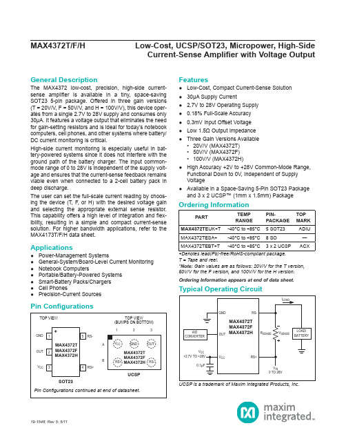
General DescriptionThe MAX4372 low-cost, precision, high-side current-sense amplifier is available in a tiny, space-saving SOT23 5-pin package. Offered in three gain versions (T = 20V/V, F = 50V/V, and H = 100V/V), this device oper-ates from a single 2.7V to 28V supply and consumes only 30μA. It features a voltage output that eliminates the need for gain-setting resistors and is ideal for today’s notebook computers, cell phones, and other systems where battery/ DC current monitoring is critical.High-side current monitoring is especially useful in bat-tery-powered systems since it does not interfere with the ground path of the battery charger. The input common-mode range of 0 to 28V is independent of the supply volt-age and ensures that the current-sense feedback remains viable even when connected to a 2-cell battery pack in deep discharge.The user can set the full-scale current reading by choos-ing the device (T, F, or H) with the desired voltage gain and selecting the appropriate external sense resistor. This capability offers a high level of integration and flex-ibility, resulting in a simple and compact current-sense solution. For higher bandwidth applications, refer to the MAX4173T/F/H data sheet.Applications●Power-Management Systems●General-System/Board-Level Current Monitoring●Notebook Computers●Portable/Battery-Powered Systems●Smart-Battery Packs/Chargers●Cell Phones●Precision-Current Sources Features●Low-Cost, Compact Current-Sense Solution●30μA Supply Current● 2.7V to 28V Operating Supply●0.18% Full-Scale Accuracy●0.3mV Input Offset Voltage●Low 1.5Ω Output Impedance●Three Gain Versions Available• 20V/V (MAX4372T)• 50V/V (MAX4372F)• 100V/V (MAX4372H)●High Accuracy +2V to +28V Common-Mode Range,Functional Down to 0V, Independent of SupplyVoltage●Available in a Space-Saving 5-Pin SOT23 Packageand 3 x 2 UCSP™ (1mm x 1.5mm) Package Ordering Information appears at end of data sheet.UCSP is a trademark of Maxim Integrated Products, Inc.19-1548; Rev 5; 5/11+Denotes lead(Pb)-free/RoHS-compliant package.T = Tape and reel.*Note: Gain values are as follows: 20V/V for the T version,50V/V for the F version, and 100V/V for the H version. Current-Sense Amplifier with Voltage OutputPin ConfigurationsOrdering InformationPARTTEMPRANGEPIN-PACKAGETOPMARK MAX4372T EUK+T-40°C to +85°C 5 SOT23ADIU MAX4372TESA+-40°C to +85°C8 SO—MAX4372TEBT+T-40°C to +85°C 3 x 2 UCSP ACXV CC , RS+, RS- to GND .........................................-0.3V to +30V OUT to GND ..........................................................-0.3V to +15V Differential Input Voltage (V RS+ - V RS-) .............................±0.3V Current into Any Pin .........................................................±10mA Continuous Power Dissipation (T A = +70°C)5-Pin SOT23 (derate 3.9mW/°C above +70°C) .......312.6mW 8-Pin SO (derate 7.4mW/°C above +70°C) ..............588.2mW 3 x 2 UCSP (derate 3.4mW/°C above +70°C) .........273.2mWOperating Temperature Range ...........................-40°C to +85°C Storage Temperature Range ............................-65°C to +150°C Lead Temperature (soldering, 10s) .................................+300°C Soldering Temperature (reflow) .......................................+260°C(V RS+ = 0 to 28V, V CC = 2.7V to 28V, V SENSE = 0V, R LOAD = 1MΩ, T A = T MIN to T MAX , unless otherwise noted. Typical values are at T A = +25°C.) (Note 1)Current-Sense Amplifier with Voltage OutputAbsolute Maximum RatingsStresses beyond those listed under “Absolute Maximum Ratings” may cause permanent damage to the device. These are stress ratings only, and functional operation of the device at these or any other conditions beyond those indicated in the operational sections of the specifications is not implied. Exposure to absolute maximum rating conditions for extended periods may affect device reliability.Electrical CharacteristicsPARAMETERSYMBOL CONDITIONSMIN TYPMAX UNITS Operating Voltage Range (Note 2)V CC 2.728V Common-Mode Input Range (Note 3)V CMR 028V Common-Mode Rejection CMR V RS+ > 2V85dB Supply Current I CC V RS+ > 2V, V SENSE = 5mV 3060μA Leakage CurrentI RS+, I RS-V CC = 0V, V RS+ = 28V 0.051.2μAInput Bias CurrentI RS+V RS+ > 2V 01μAV RS+ ≤ 2V -25+2I RS-V RS+ > 2V 02V RS+ ≤ 2V-50+2Full-Scale Sense Voltage (Note 4)V SENSEGain = 20V/V or 50V/V 150mV Gain = 100V/V 100Input Offset Voltage (Note 5)V OST A = +25°CV CC = V RS+ = 12V MAX4372_ESA 0.3±0.8mVMAX4372_EUK, _EBT 0.3±1.3T A = T MIN to T MAX V CC = V RS+ = 12VMAX4372_ESA ±1.1MAX4372_EUK, _EBT±1.9Full-Scale Accuracy (Note 5)V SENSE = 100mV, V CC = 12V,V RS+ = 12V, T A = +25°C (Note 7)±0.18±3%Total OUT Voltage Error (Note 6)V SENSE = 100mV, V CC = 12V,V RS+ = 12V (Note 7)±6V SENSE = 100mV, V CC = 28V,V RS+ = 28V (Note 7)±0.15±7V SENSE = 100mV, V CC = 12V,V RS+ = 0.1V (Note 7)±1±28V SENSE = 6.25mV, V CC = 12V,V RS+ = 12V (Note 8)±0.15(V RS+ = 0 to 28V, V CC = 2.7V to 28V, V SENSE = 0V, R LOAD = 1MΩ, T A = T MIN to T MAX , unless otherwise noted. Typical values are at T A = +25°C.) (Note 1)Note 1: All devices are 100% production tested at T A = +25°C. All temperature limits are guaranteed by design.Note 2: Guaranteed by PSR test.Note 3: Guaranteed by OUT voltage error test.Note 4: Output voltage is internally clamped not to exceed 12V.Note 5: V OS is extrapolated from the gain accuracy tests.Note 6: Total OUT voltage error is the sum of gain and offset voltage errors.Note 7: Measured at I OUT = -500μA (R LOAD = 4kΩ for gain = 20V/V, R LOAD = 10kΩ for gain = 50V/V, R LOAD = 20kΩ for gain = 100V/V).Note 8: 6.25mV = 1/16 of 100mV full-scale voltage (C/16).Note 9: The device does not reverse phase when overdriven.Current-Sense Amplifier with Voltage OutputElectrical Characteristics (continued)PARAMETERSYMBOL CONDITIONSMINTYP MAXUNITSOUT Low Voltage(MAX4372T, MAX4372F)V OLV CC = 2.7V,V SENSE = -10mV, V RS+ = 28V I OUT = 10μA 2.6mVI OUT = 100μA 965OUT Low Voltage (MAX4372H)V OLV CC = 2.7V,V SENSE = -10mV, V RS+ = 12VI OUT = 10μA 2.6mVI OUT = 100μA965OUT High VoltageV CC - V OHV CC = 2.7V, I OUT = -500μA, V SENSE = 250mV, V RS+ = 28V0.10.25V-3dB Bandwidth BWV RS+ = 12V,V CC = 12V,C LOAD = 10pFV SENSE = 20mV,gain = 20V/V275kHzV SENSE = 20mV,gain = 50V/V 200V SENSE = 20mV,gain = 100V/V 110V SENSE = 6.25mV50GainMAX4372T20V/VMAX4372F 50MAX4372H100Gain AccuracyV SENSE = 20mV to 100mV, V R S + = 12V T A = +25°C ±0.25±2.5%T A = -40°C to +85°C ±5.5OUT Settling Time to 1% of Final ValueGain = 20V/V, V CC = 12V, V RS+ = 12V, C LOAD = 10pFV SENSE = 6.25mV to 100mV20µsV SENSE = 100mV to 6.25mV20Capacitive-Load Stability No sustained oscillations1000pF OUT Output Resistance R OUT V SENSE = 100mV 1.5ΩPower-Supply Rejection PSRV OUT = 2V, V RS+ > 2V7585dB Power-Up Time to 1% of Final ValueV CC = 12V, V RS+ = 12V,V SENSE = 100mV, C LOAD = 10pF 0.5ms Saturation Recovery Time (Note 9)V CC = 12V, V RS+ = 12V, C LOAD = 10pF0.1ms(V CC = 12V, V RS+ = 12V, V SENSE = 100mV, T A = +25°C, unless otherwise noted.)Current-Sense Amplifier with Voltage OutputTypical Operating Characteristics25.027.530.032.535.0SUPPLY CURRENT vs. SUPPLY VOLTAGESUPPLY VOLTAGE (V)S U P P L Y C U R R E N T (µA )121648202428-1.2-0.8-1.0-0.2-0.4-0.60.40.200.6010515202530TOTAL OUTPUT ERROR vs. SUPPLY VOLTAGESUPPLY VOLTAGE (V)O U T P U T E R R O R (%)00.20.40.60.81.01.21.41.610515202530TOTAL OUTPUT ERROR vs. COMMON-MODE VOLTAGECOMMON-MODE VOLTAGE (V)O U T P U T E R R O R (%)510152025303540-401060-153585SUPPLY CURRENT vs. TEMPERATURETEMPERATURE (°C)S U P P L Y C U R R E N T (µA )-1.0-0.50.501.01.5010050150200250300TOTAL OUTPUT ERROR vs. V SENSEV SENSE (mV)O U T P U T E R R O R (%)-1.0-0.9-0.8-0.7-0.6-0.5-0.4-0.3-0.2-0.10GAIN ACCURACY vs. TEMPERATURETEMPERATURE (°C)G A I N A C C U R A C Y (%)-401060-15358528.029.028.530.029.531.531.030.532.0SUPPLY CURRENTvs. COMMON-MODE VOLTAGECOMMON-MODE VOLTAGE (V)S U P P L Y C U R R E N T (µA )-45-90100100k10k 1k POWER-SUPPLY REJECTIONvs. FREQUENCY-75-85-55-65-40-70-80-50-60M A X 4372T t o c 06FREQUENCY (Hz)P S R (d B )-1.0-0.8-0.6-0.4-0.200.20.40.60.81.0-401060-153585TOTAL OUTPUT ERROR vs. TEMPERATURETEMPERATURE (°C)T O T A L O U T P U T E R R O R (%)(V CC = 12V, V RS+ = 12V, V SENSE = 100mV, T A = +25°C, unless otherwise noted.)Current-Sense Amplifier with Voltage OutputTypical Operating Characteristics (continued)V OUTV SENSE600mV200mV30mV10mV MAX4372TSMALL-SIGNAL TRANSIENT RESPONSEMAX4372T toc1020µs/div V OUTV SENSE1V3V50mV 150mV MAX4372TLARGE-SIGNAL TRANSIENT RESPONSEMAX4372T toc1320µs/divV OUTV SENSE 010V0100mV MAX4372HLARGE-SIGNAL TRANSIENT RESPONSE20µs/divMAX4372T toc15V OUTV SENSE2.5V7.5V50mV 150mVMAX4372FLARGE-SIGNAL TRANSIENT RESPONSE20µs/divMAX4372T toc143-81k100k10k1MSMALL-SIGNAL GAIN vs. FREQUENCY-7FREQUENCY (Hz)G A I N (d B)-6-5-4-3-2-1012V OUTV SENSE 1.5V0.5V30mV 10mVMAX4372FSMALL-SIGNAL TRANSIENT RESPONSEMAX4372T toc1120µs/div V OUTV SENSE 3V1V30mV10mV MAX4372HSMALL-SIGNAL TRANSIENT RESPONSEMAX4372T toc1220µs/divDetailed DescriptionThe MAX4372 high-side current-sense amplifier features a 0 to 28V input common-mode range that is indepen-dent of supply voltage. This feature allows the monitoring of current flow out of a battery in deep discharge, and also enables high-side current sensing at voltages far in excess of the supply voltage (V CC).Current flows through the sense resistor, generating a sense voltage (Figure 1. Functional Diagram). Since A1’s inverting input is high impedance, the voltage on the negative terminal equals V IN - V SENSE. A1 forces its positive terminal to match its negative terminal; therefore, the voltage across R G1 (V IN - V1-) equals V SENSE. This creates a current to flow through R G1 equal to V SENSE/ R G1. The transistor and current mirror amplify the current by a factor of β. This makes the current flowing out of the current mirror equal to:I M = β V SENSE/R G1A2’s positive terminal presents high impedance, so this current flows through R GD, with the following result:V2+ = R GD β x V SENSE/R G1R1 and R2 set the closed-loop gain for A2, which ampli-fies V2+, yielding:V OUT = R GD x β x V SENSE/R G1 (1 + R2/R1)The gain of the device equals:OUT SEN G1SE RGD x (1 + R2/R1)V V/Rβ=Applications Information Recommended Component ValuesThe MAX4372 operates over a wide variety of current ranges with different sense resistors. Table 1 lists com-mon resistor values for typical operation of the MAX4372.Choosing R SENSEGiven the gain and maximum load current, select R SENSE such that V OUT does not exceed V CC - 0.25V or 10V. To measure lower currents more accurately, use a high value for R SENSE. A higher value develops a higher sense volt-age, which overcomes offset voltage errors of the internal current amplifier.In applications monitoring very high current, ensure R SENSE is able to dissipate its own I2R losses. If the resistor’s rated power dissipation is exceeded, its value may drift or it may fail altogether, causing a differential voltage across the terminals in excess of the absolute maximum ratings.Figure 1. Functional DiagramCurrent-Sense Amplifier with Voltage OutputPin/Bump DescriptionPIN BUMPNAME FUNCTIONSOT23SO UCSP13A2GND Ground24A3OUT Output Voltage. V OUT is proportional to the magnitude of V SENSE (V RS+ - V RS-).31A1V CC Supply Voltage. Use at least a 0.1μF capacitor to decouple V CC from fast transients.48B1RS+Power Connection to the External Sense Resistor56B3RS-Load-Side Connection to the External Sense Resistor —2, 5, 7—N.C.No Connection. Not internally connected.Using a PC Board Trace as R SENSEIf the cost of R SENSE is an issue and accuracy is not criti-cal, use the alternative solution shown in Figure 2. This solution uses copper PC board traces to create a sense resistor. The resistivity of a 0.1in wide trace of 2oz copper is about 30mΩ/ft. The resistance temperature coefficient of copper is fairly high (approximately 0.4%/°C), so sys-tems that experience a wide temperature variance must compensate for this effect. In addition, self-heating intro-duces a nonlinearity error. Do not exceed the maximum power dissipation of the copper trace.For example, the MAX4372T (with a maximum load cur-rent of 10A and an R SENSE of 5mΩ) creates a full-scale V SENSE of 50mV that yields a maximum V OUT of 1V. R SENSE, in this case, requires about 2in of 0.1in wide copper trace.UCSP Applications InformationFor the latest application details on UCSP construction, dimensions, tape carrier information, printed circuit board techniques, bump-pad layout, and recommended reflow temperature profile, as well as the latest information on reliability testing results, go to the Maxim’s website at /ucsp to find the Application Note: UCSP—A Wafer-Level Chip-Scale Package.Figure 2. Connections Showing Use of PC BoardTable 1. Recommended Component ValuesCurrent-Sense Amplifier with Voltage OutputFULL-SCALE LOAD CURRENT,I LOAD (A)CURRENT-SENSERESISTOR,R SENSE (mΩ)GAIN(V/V)FULL-SCALE OUTPUTVOLTAGE (FULL-SCALEV SENSE = 100mV),V OUT (V)0.1100020 2.0 50 5.0 10010.0110020 2.0 50 5.0 10010.052020 2.0 50 5.0 10010.0101020 2.0 50 5.0 10010.0Current-Sense Amplifier with Voltage Output Ordering Information (continued)Pin Configurations (continued)PARTTEMPRANGEPIN-PACKAGETOPMARKMAX4372F EUK+T-40°C to +85°C 5 SOT23ADIV MAX4372FESA+-40°C to +85°C8 SO—MAX4372FEBT+T-40°C to +85°C 3 x 2 UCSP ACX MAX4372H EUK+T-40°C to +85°C 5 SOT23ADIW MAX4372HESA+-40°C to +85°C8 SO—MAX4372HEBT+T-40°C to +85°C 3 x 2 UCSP ACZChip InformationPROCESS: BiCMOS+Denotes lead(Pb)-free/RoHS-compliant package. T = Tape and reel.Current-Sense Amplifier with Voltage Output Package InformationFor the latest package outline information and land patterns (footprints), go to /packages. Note that a “+”, “#”, or “-” in the package code indicates RoHS status only. Package drawings may show a different suffix character, but the drawing pertains to the package regardless of RoHS status.PACKAGE TYPE PACKAGE CODE OUTLINE ND PATTERN NO.5 SOT23U5+121-005790-01748 SO S8+221-004190-00965 UCSP B6+221-0097—Note: MAX4372_EBT uses package code B6-2.Current-Sense Amplifier with Voltage Output Package Information (continued)For the latest package outline information and land patterns (footprints), go to /packages. Note that a “+”, “#”, or “-” in the package code indicates RoHS status only. Package drawings may show a different suffix character, but the drawing pertains to the package regardless of RoHS status.Current-Sense Amplifier with Voltage Output Package Information (continued)For the latest package outline information and land patterns (footprints), go to /packages. Note that a “+”, “#”, or “-” in the package code indicates RoHS status only. Package drawings may show a different suffix character, but the drawing pertains to the package regardless of RoHS status. Maxim Integrated │11Maxim Integrated cannot assume responsibility for use of any circuitry other than circuitry entirely embodied in a Maxim Integrated product. No circuit patent licenses are implied. Maxim Integrated reserves the right to change the circuitry and specifications without notice at any time. The parametric values (min and max limits) shown in the Electrical Characteristics table are guaranteed. Other parametric values quoted in this data sheet are provided for guidance.Maxim Integrated and the Maxim Integrated logo are trademarks of Maxim Integrated Products, Inc.Current-Sense Amplifier with Voltage Output© 2011 Maxim Integrated Products, Inc. │ 12Revision HistoryREVISIONNUMBERREVISION DATE DESCRIPTION PAGES CHANGED 47/09Updated feature in accordance with actual performance of the product 155/11Updated V RST conditions to synchronize with tested material and addedlead-free designation 1–3, 8For pricing, delivery, and ordering information, please contact Maxim Direct at 1-888-629-4642, or visit Maxim Integrated’s website at .。


MAX518—串行8位D/A芯片
Maxim公司生产的MAX518芯片是一种采用二线串行接口的8位D/A转换芯片,采用单5V供电,具有两路8位模拟量输出口。
MAX518是8位电压输出型数摸转换器,采用fc的双总线串行接口,支持多个设备的通信,内部有精密输出缓冲源,支持双极性工作方式,工作电源电压为5V,由两片DAC集成,具有两路输出。
MAX518的两块DAC均由电源电压提供参考源,无需外部接入。
数据传输速率可高达400Kbit/s。
引脚如图1所示。
图1:MAX518封装图
MAX518引脚功能如下:
D/OUT0、D/OUTl为数/模转换的电压输出;
ADO、AD1为地址输入端,用于设置器件的从动地址;
SOL为串行时钟输入,SDA为串行数据输入。
MAX518的D/A转换数据通过SCL和SDA串行输入,芯片内部把输入数据中地址位与ADO、AD1所表示的地址比较,如符合则把数据存放在8位数据缓冲寄存器中,然后经过D/A转换电路和运放分别从OUT0、OUT1输出0~5V 的电压信号。
应用原理如图2所示:
图2:应用原理图
MAX5 18与PIC的接口为二线制,MAX5 18芯片与PlC16F877接口时,仅需两个引脚,可以直接与PlC16F877的SOL和SDA相连。
如果考虑抗干扰问题,可以采用光电隔离的方法消除干扰。
若ADO、AD1接地,则表示该芯片的地址为00,可以根据需要最多同时连接4片(不同地址)MAX518芯片。

高端电流检测放大器性能分析 MAX4372 MAX4173 MAX4080文章发布人:gxy 共193人阅读文字大小:[ 大中小 ] 文字背景色:在讨论器件功能时,检流放大器可以看作一个输入级浮空的仪表/差分放大器。
这意味着即使器件采用VCC=3.3V或5V单电源供电,在输入共模电压远高于电源电压的条件下,器件仍然能够正常放大差分输入信号。
检流放大器的共模电压可以很高,例如可以高达28V(MAX4372和MAX4173)或76V(MAX4080和MAX4081)。
检流放大器的这一特性使其非常适合高端电流检测应用,这类应用往往需要对高压侧检流电阻两端的微小电压进行放大,并馈入到低压ADC或低压模拟控制环路进行处理。
这种情况下,通常需要在信号源端(例如检流电阻两端)对电流检测信号进行滤波。
可以采用差分滤波器(图1)滤除负载电流和检流电压的“毛刺”,也可以采用共模滤波器(图2)以增强在出现共模电压尖峰或瞬时过压时的ESD 保护能力。
合理选择元件构建滤波器,如果元件选择不当,则会引入一些无法预知的失调电压和增益误差,降低电路性能。
滤波器的选择MAX4173检流放大器如图3所示,该器件的检流电阻可直接连接到芯片的RS+和RS-端。
器件内部的运算放大器将检流电阻两端的差分电压恢复成RG1两端的差分电压,即ILOAD×RSENSE=VSENSE=IRG1×RG1。
然后,内部电流镜对电流IRG1进行电平转换和放大,产生输出电流IRGD。
MAX4173的内部电路中RGD=12kΩ,而RG1=6kΩ。
因此,由于RGD和RG1为片上电阻,实际阻值会因不同的半导体工艺而产生多达±30%的差异。
但是,因为最终增益精度取决于RGD和RG1的比例,所以可以很好地控制增益,并在生产过程中灵活调整。
构建差分/共模滤波器(如图1和图2所示)时,需要在检流电阻的RSENSE+和RSENSE-端与器件的RS+和RS-引脚之间接入串联电阻,此时相当于改变了芯片的RG1和RG2。

MAX4376/MAX4377/MAX4378Single/Dual/Quad, High-Side Current-SenseAmplifiers with Internal Gain________________________________________________________________Maxim Integrated Products119-1781; Rev 3; 5/04General DescriptionThe MAX4376/MAX4377/MAX4378 single, dual, and quad precision high-side current-sense amplifiers are available in space-saving packages. They feature buffered voltage outputs that eliminate the need for gain-setting resistors and are ideal for today’s notebook computers, cell phones, and other systems where cur-rent monitoring is critical. These precision devices are offered in three fixed-gain versions of 20, 50, and 100:GAIN SUFFIX 20T 50F 100 HFor example, MAX4376TAUK is a single high-side amplifier with a gain of 20.High-side current monitoring is especially useful in bat-tery-powered systems since it does not interfere with the ground path of the battery charger. The input com-mon-mode range of 0 to +28V is independent of the supply voltage and ensures that the current-sense feedback remains viable even when connected to a battery pack in deep discharge.The full-scale current reading can be set by choosing the appropriate voltage gain and external-sense resis-tor. This capability offers a high level of integration and flexibility, resulting in a simple and compact current-sense solution.The MAX4376/MAX4377/MAX4378 operate over a sup-ply voltage range of +3V to +28V, draw 1mA of supply current per amplifier, and operate over the full automo-tive temperature range of -40°C to +125°C. These devices have a wide bandwidth of 2MHz, making them suitable for use inside battery-charger control loops.The buffered outputs drive up to 2mA of output current into a ground-referenced load.The MAX4376 is available in a tiny 5-pin SOT23 pack-age. The MAX4377/MAX4378 are available in space-saving 8-pin µMAX and 14-pin TSSOP packages,respectively.ApplicationsFeatureso Low-Cost, Single/Dual/Quad, High-Side Current-Sense Amplifierso ±0.5% Typical Full-Scale Accuracy o +3V to +28V Supply OperationoAdjustable Current-Sense Capability with External Sense Resistoro Buffered Output Voltage with 2mA Drive o 1mA (typ) Supply Currento 2.0MHz Bandwidth (Gain = +20V/V)o Automotive Temperature Range (-40°C to +125°C)o Full 0 to 28V Common-Mode Range, Independent of Supply Voltageo Three Gain Versions Available+20V/V (MAX437_T)+50V/V (MAX437_F)+100V/V (MAX437_H)o Available in Space-Saving 5-Pin SOT23 (Single), 8-Pin µMAX (Dual), and 14-Pin TSSOP (Quad)Ordering Information continued at end of data sheet.Ordering InformationNotebook Computers Current-Limited Power SuppliesFuel Gauges in PCGeneral-System/Board-Level Current Monitoring Battery ChargersPortable/Battery-Powered Systems Cell PhonesSmart Battery Packages Automotive Current Detect Power Management SystemsPA Bias ControlPin ConfigurationsFor pricing, delivery, and ordering information,please contact Maxim/Dallas Direct!at 1-888-629-4642, or visit Maxim’s website at .M A X 4376/M A X 4377/M A X 4378Single/Dual/Quad, High-Side Current-Sense Amplifiers with Internal GainABSOLUTE MAXIMUM RATINGSELECTRICAL CHARACTERISTICS(V RS+= 0 to 28V, V SENSE = (V RS+- V RS-) = 0V, V CC = +3.0V to +28V, R L = ∞, T A = T MIN to T MAX,unless otherwise noted. Typical values are at T A = 25°C.) (Note 1)Stresses beyond those listed under “Absolute Maximum Ratings” may cause permanent damage to the device. These are stress ratings only, and functional operation of the device at these or any other conditions beyond those indicated in the operational sections of the specifications is not implied. Exposure to absolute maximum rating conditions for extended periods may affect device reliability.V CC , RS+, RS- to GND...........................................-0.3V to +30V OUT to GND...............................................-0.3V to (V CC + 0.3V) Differential Input Voltage (V RS+- V RS- ).................................±8V Output Short Circuit to V CC ........................................Continuous Output Short Circuit to GND.....................................................1s Current into Any Pin..........................................................±20mA Continuous Power Dissipation (T A = +70°C)5-Pin SOT23 (derate 7.1mW/°C above +70°C)............571mW 8-Pin µMAX (derate 4.5mW/°C above +70°C).............362mW 8-Pin SO (derate 5.88mW/°C above +70°C)................471mW14-Pin SO (derate 8.33mW/°C above +70°C)..............667mW 14-Pin TSSOP (derate 9.1mW/°C above +70°C).........727mW Operating Temperature Range .........................-40°C to +125°C Junction Temperature......................................................+150°C Storage Temperature Range.............................-65°C to +150°C Lead Temperature (soldering, 10s).................................+300°CMAX4376/MAX4377/MAX4378Single/Dual/Quad, High-Side Current-SenseAmplifiers with Internal Gain_______________________________________________________________________________________3ELECTRICAL CHARACTERISTICS (continued)(V RS+= 0 to 28V, V SENSE = (V RS+- V RS-) = 0V, V CC = +3.0V to +28V, R L = ∞, T A = T MIN to T MAX,unless otherwise noted. Typical values are at T A = 25°C.) (Note 1)Note 4:V SENSE such that V OUT is in saturation.M A X 4376/M A X 4377/M A X 4378Single/Dual/Quad, High-Side Current-Sense Amplifiers with Internal Gain 4_______________________________________________________________________________________0.500.650.600.550.700.750.800.850.900.951.00010515202530SUPPLY CURRENT (PER AMPLIFIER)vs. SUPPLY VOLTAGESUPPLY VOLTAGE (V)S U P P L Y C U R R E N T (m A )0.40.20.80.61.21.01.4-50025-255075100125SUPPLY CURRENT (PER AMPLIFIER)vs. TEMPERATURETEMPERATURE (°C)S U P P L Y C U R R E N T (m A )-1.0-0.8-0.6-0.4-0.20.00.20.40.60.81.01.20510********TOTAL OUTPUT ERRORvs. SUPPLY VOLTAGE (V SENSE= 100mV)SUPPLY VOLTAGE (V)T O T A L O U T P U T E R R O R (%)-1-20123456TOTAL OUTPUT ERRORvs. SUPPLY VOLTAGE (V SENSE = 6.25mV)T O T A L O U T P U T E R R O R (%)-4-3010515202530SUPPLY VOLTAGE (V)-1.0-0.4-0.6-0.8-0.200.20.40.60.81.0010*********TOTAL OUTPUT ERROR vs. COMMON-MODE VOLTAGECOMMON-MODE VOLTAGE (V)T O T A L O U T P U T E R R O R (%)-2.0-1.0-1.50-0.51.51.00.52.0GAIN ACCURACY vs. TEMPERATURETEMPERATURE (°C)G A I N A C C U R A C Y (%)-50-25255075100125Typical Operating Characteristics(V CC = V RS+ = 12V, V SENSE = 100mV, T A = +25°C.)-1.0-0.6-0.8-0.2-0.40.200.40.80.61.0-50025-255075100125150TOTAL OUTPUT ERROR vs. TEMPERATURETEMPERATURE (°C)T O T A L O U T P U T E R R O R (%)MAX4376/MAX4377/MAX4378Single/Dual/Quad, High-Side Current-SenseAmplifiers with Internal Gain_______________________________________________________________________________________5Typical Operating Characteristics (continued)(V CC = V RS+ = 12V, V SENSE = 100mV, T A = +25°C.)2µs/divMAX4376FSMALL-SIGNAL TRANSIENT RESPONSE(V SENSE = 95mV TO 100mV)IN 5mV/divOUT 100mV/div95mV100mV 5V4.75VC L = 15pF R L = 2.5k Ω2µs/divMAX4376HSMALL-SIGNAL TRANSIENT RESPONSE(V SENSE = 95mV to 100mV)IN 5mV/divOUT 200mV/div95mV100mV 10V9.5VC L = 15pF R L = 5k Ω2µs/div MAX4376TLARGE-SIGNAL TRANSIENT RESPONSE(V SENSE = 6mV to 100mV)IN 45mV/divOUT 500mV/div6mV 100mV 2V0.120VC L = 15pF R L = 1k Ω-20-121435TOTAL OUTPUT ERRORvs. FULL-SCALE SENSE VOLTAGEV SENSE (mV)T O T A L O U T P U T E R R O R (%)501001502002µs/divMAX4376TSMALL-SIGNAL TRANSIENT RESPONSE(V SENSE = 95mV TO 100mV)IN 5mV/divOUT 50mV/div95mV100mV 2.0V1.9VC L = 15pF R L =1k Ω2µs/divMAX4376FLARGE-SIGNAL TRANSIENT RESPONSE(V SENSE = 6mV to 100mV)IN 45mV/divOUT 2V/div6mV100mV 5V0.3VC L = 15pF R L = 2.5k ΩM A X 4376/M A X 4377/M A X 4378Single/Dual/Quad, High-Side Current-Sense Amplifiers with Internal Gain 6_______________________________________________________________________________________2µs/divMAX4376HLARGE-SIGNAL TRANSIENT RESPONSE(V SENSE = 6mV to 100mV)IN 45mV/divOUT 3V/div6mV 100mV10V0.6V1.E+041.E+071.E+061.E+05SMALL-SIGNAL GAIN vs. FREQUENCY15535254520104030FREQUENCY (Hz)G A I N (d B )TIME (500ns)OVERDRIVE RESPONSEAV = +20V/VIN200mV/divOUT 2V/div350mV750mVV OH7VMAX4376/7/8 toc16010050200150350300250400OUTPUT LOW vs. TEMPERATURETEMPERATURE (°C)O U T P U T L O W (m V )-50-25255075100125Typical Operating Characteristics (continued)(V CC = V RS+ = 12V, V SENSE = 100mV, T A = +25°C.)MAX4376/MAX4377/MAX4378Single/Dual/Quad, High-Side Current-SenseAmplifiers with Internal Gain_______________________________________________________________________________________7Detailed DescriptionThe MAX4376/MAX4377/MAX4378 high-side current-sense amplifiers feature a 0 to +28V input common-mode range that is independent of supply voltage. This feature allows the monitoring of current out of a battery in deep discharge and also enables high-side current sensing at voltages greater than the supply voltage (V CC ).The MAX4376/MAX4377/MAX4378 operate as follows:current from the source flows through R SENSE to the load (Figure 1). Since the internal sense amplifier ’s inverting input has high impedance, negligible current flows through RG2 (neglecting the input bias current).Therefore, the sense amplifier ’s inverting-input voltage equals V SOURCE - (I LOAD )(R SENSE ).The amplifier ’s open-loop gain forces its noninverting input to the same voltage as the inverting input.Therefore, the drop across RG1 equals (I LOAD )(R SENSE ). Since I RG1flows through RG1, I RG1=(I LOAD )(R SENSE )/RG1. The internal current mirror multi-plies I RG1by a current gain factor, β, to give I RGD = βx I RG1. Solving I RGD = βx (I LOAD )(R SENSE )/RG1.Therefore:V OUT = βx (RGD/RG1)(R SENSE x I LOAD ) x amp gain where amp gain is 2, 5, or 10.The part ’s gain equals (βx RGD / RG1) x amp gain.Therefore:V OUT = (GAIN)(R SENSE )(I LOAD )where GAIN = 20 for MAX437_T.GAIN = 50 for MAX437_F.GAIN = 100 for MAX437_H.the appropriate gain version of the MAX4376/MAX4377/MAX4378.Applications InformationRecommended Component ValuesThe MAX4376/MAX4377/MAX4378 sense a wide variety of currents with different sense resistor values. Table 1lists common resistor values for typical operation of the MAX4376/MAX4377/MAX4378.Choosing R SENSETo measure lower currents more accurately, use a high value for R SENSE . The high value develops a higher sense voltage that reduces offset voltage errors of the internal op amp.I n applications monitoring very high currents, R SENSE must be able to dissipate the I 2R losses. If the resistor ’s rated power dissipation is exceeded, its value may drift or it may fail altogether, causing a differential voltage across the terminals in excess of the absolute maxi-mum ratings.If I SENSE has a large high-frequency component, mini-mize the inductance of R SENSE . Wire-wound resistors have the highest inductance, metal-film resistors are somewhat better, and low-inductance metal-film resis-tors are best suited for these applications.Bidirectional Current-Sense AmplifierSystems such as laptop computers and other devices that have internal charge circuitry require a precise bidirectional current-sense amplifier to monitor accu-rately the battery ’s current regardless of polarity. Figure 2 shows the MAX4377 used as a bidirectional currentPin DescriptionM A X 4376/M A X 4377/M A X 4378Single/Dual/Quad, High-Side Current-Sense Amplifiers with Internal Gain 8_______________________________________________________________________________________Current Source CircuitFigure 3 shows a block diagram using the MAX4376with a switching regulator to make a current source.Figure 2. Bidirectional Current MonitorSingle/Dual/Quad, High-Side Current-SenseAmplifiers with Internal GainMAX4376/MAX4377/MAX4378Maxim cannot assume re sponsibility for use of any circuitry othe r than circuitry e ntire ly e mbodie d in a Maxim product. No circuit pate nt lice nse s are implied. Maxim reserves the right to change the circuitry and specifications without notice at any time.9_____________________Maxim Integrated Products, 120 San Gabriel Drive, Sunnyvale, CA 94086 408-737-7600©2004 Maxim Integrated ProductsPrinted USAis a registered trademark of Maxim Integrated Products.Typical Operating CircuitOrdering Information (continued)Chip InformationMAX4376_ TRANSISTOR COUNT: 162MAX4377_ TRANSISTOR COUNT: 324MAX4378_ TRANSISTOR COUNT: 648PROCESS: BiCMOS。