欧姆龙液位开关说明书
- 格式:doc
- 大小:1.24 MB
- 文档页数:56
1MC-510目录快速测量方法 (2)安全注意事项 (3)商品构成 (6)体温的基本常识 (8)测量方法 (9)电池更换方法 (17)有疑问时 (18)显示出错时 ................20保养与保管 ................22规格 ..........................23咨询 .. (24)产品保证书 (25)保修卡 .......................26非常感谢您购买欧姆龙速测体温宝,为了正确使 ⏹用本产品,请务必在使用之前阅读本产品说明书。
为了安全正确地使用本产品,请阅读并充分理解 ⏹本说明书中的“安全注意事项”。
敬请经常把说明书放在身边以便查阅。
⏹本说明书兼作产品质量保证书,故请妥善保管勿 ⏹丢失。
快速测量方法3说明书中所表示的警告记号和警告图例,其目的 ⏹是为了使您能够安全、正确地使用本产品,并防止对您及他人造成伤害。
警告记号、图例及其含义如下:⏹※ 所谓物品损坏是指有关房屋、家产及家畜、宠物的损害。
安全注意事项45建议• 当您把所测体温告诉医生时,请说明您是用耳式体温计进行测量的。
• 请不要用于人体耳部以外的体温测量。
• 请不要强行碰撞、摔落、踩踏和摇动本体。
•请勿在测量过程中在体温计附近使用移动电话。
• 请勿拆卸、修理和改造本体。
• 本产品不防水。
请注意不要让液体(酒精、水滴、热水等)进入本体内部。
6☆ 探测器保护罩是消耗品,使用完结后请购买新的探测器保护罩。
☆ 探测器保护罩脏污破损时,请更换探测器保护罩,因为表面的脏污和破损会影响测量精度。
78体温的基本常识测量腋下和舌下的体温易受外界温度、汗水和唾液等的影响,所以较之所测的温度偏低,而测量耳温可更好地反映脑部温度,快速测得正确的体温值。
为了正确判断发烧的状态,请了解正常情况下家庭成员的耳温。
耳温和腋下温度分布了解家庭成员正常状态时耳温。
耳温与腋下温度存在差异,通过正常状态时耳部与腋下的「温度差」可以大致比较出发烧时的「温度差」。
外贴式液位开关隔爆型安装使用说明书(201405A)陕西声科电子中国西安高新技术产业开发区©本说明书的版权和最终解释权归声科电子有限公司所用。
目录1.使用说明 (1)2.仪表保修及服务范围 (1)3.仪表技术性能 (2)4.开箱检验及注意事项 (2)4.1 开箱检验 (2)4.2 注意事项 (3)5.仪表各部件 (3)6.仪表安装 (4)6.1 超声波探头的安装 (4)6.2 仪表主机安装 (8)6.3仪表的安装方式 (11)7.仪表电气连接 (12)7.1 仪表电气连接图 (12)7.2 仪表供电 (12)8. 仪表设置及使用 (13)8.1 仪表参数设置人机接口说明 (13)8.2 仪表操作目录树 (14)8.3 仪表运行界面示意 (15)8.4 仪表校准操作 (16)8.5仪表校准操作图示 (16)9.外贴式液位开关选型表 (19)10.仪表适用范围 (20)11.性能指标 (20)12.仪表故障处理 (21)1、使用说明本说明书全面阐述了外贴式液位开关的安装、操作及使用方法。
通过本说明书,用户可以顺利的完成对外贴式液位开关的安装、使用及维护工作。
本说明书的编制是以外贴式液位开关的安装、操作步骤为顺序,详细介绍了您在安装、使用仪表的每个环节需要完成的工作及注意事项。
在您安装、使用该仪表之前,请详细阅读本说明书。
2、仪表保修及服务范围自发货之日算起,仪表主机保修期为一年,仪表修理及维护的保修期为半年,此保修仅限于原始购买者及或声科电子指定经销商的仪表使用用户,而不适用于任何声科电子认为因错误使用,改造、疏忽或因事故及非正常情况下使用而导致损坏的仪表。
对于在保修范围内的送回声科电子的有故障的仪表,声科电子提供免费维修。
要获得保修服务,请联系声科售后服务部并附上故障说明,经本公司许可后,将仪表寄往声科售后服务部。
如果仪表已过质保期或声科电子确认仪表故障是由于错误使用、改造、疏忽、事故及非正常条件下使用导致的,声科电子将依据外贴式液位开关维修收费标准提供维修费用预算,并在得到认可后进行维修。


CJ SeriesEtherNet/IP™ Connection GuideOMRON CorporationZW-series Displacement SensorP536-E1-01About Intellectual Property Right and TrademarksMicrosoft product screen shots reprinted with permission from Microsoft Corporation.Windows is a registered trademark of Microsoft Corporation in the USA and other countries. ODVA and EtherNet/IP™ are trademarks of ODVA.Ethernet is a registered trademark of the Xerox Corporation.Company names and product names in this document are the trademarks or registered trademarks of their respective companies.Table of Contents1.Related Manuals (1)2.Terms and Definitions (2)3.Remarks (3)4.Overview (5)5.Applicable Devices and Support Software (6)5.1.Applicable Devices (6)5.2.Device Configuration (7)6.EtherNet/IP Connection Procedure (9)6.1.EtherNet/IP Communications Settings (9)6.2.Work Flow (12)6.3.Setting Up the Displacement Sensor (13)6.4.Setting Up the PLC (21)6.5.Checking the EtherNet/IP Communications (44)7.Initialization Method (49)7.1.Initializing the PLC (49)7.2.Initializing the Displacement Sensor (50)8.Revision History (51)1. Related Manuals1. Related ManualsThe table below lists the manuals related to this document.To ensure system safety, make sure to always read and heed the information provided in all Safety Precautions, Precautions for Safe Use, and Precaution for Correct Use of manuals for each device which is used in the system.Cat. No. Model Manual nameCJ-series CJ2 CPU Unit Hardware User's Manual W472 CJ2H-CPU6[]-EIPCJ2H-CPU6[]CJ2M-CPU[][]CJ-series CJ2 CPU Unit Software User's Manual W473 CJ2H-CPU6[]-EIPCJ2H-CPU6[]CJ2M-CPU[][]EtherNet/IP™ Unit Operation Manual W465 CJ1W-EIP21CJ2H-CPU6[]-EIPCJ2M-CPU3[]W446 - CX-Programmer Operation ManualZ332 ZW-CE1[] ZW Series Displacement Sensor (Confocal Fiber Type)User's Manual2. Terms and Definitions2. Terms and DefinitionsTerm Explanation and DefinitionTag data link A function that enables cyclic tag data exchanges on an EtherNet/IPnetwork between PLCs or between PLCs and with other devices withoutusing a user program in the PLCs.Tag A tag is a unit that is used to exchange data with tag data links. Data isexchanged between the local network variables and remote networkvariables specified in the tags or between specified I/O memory areas.Tag set When a connection is established, from 1 to 8 tags (including Controllerstatus) is configured as a tag set. Each tag set represents the data thatis linked for a tag data link connection.Connection A connection is used to exchange data as a unit within which datasynchronicity is maintained.Thus, data synchronicity is maintained for all the data exchanged for thetags in one data set.Originator and Target To perform tag data links, one node requests the opening of acommunications line called "connection" to perform tag data links.The node that requests opening the connection is called "originator",and the node that receives the request is called "target".Node With EtherNet/IP network, 1 node is 1 EtherNet/IP port.Tag data link parameter The tag data link parameter is the setting data to perform the tag data link. It includes the data to set tags, tag sets, and connections.EDS file A file that contains the I/O points of EtherNet/IP devices and the parameters that can be set via EtherNet/IP.3. Remarks(1) Understand the specifications of devices which are used in the system. Allow somemargin for ratings and performance. Provide safety measures, such as installing safetycircuit in order to ensure safety and minimize risks of abnormal occurrence.(2) To ensure system safety, always read and heed the information provided in all SafetyPrecautions, Precautions for Safe Use, and Precaution for Correct Use of manuals foreach device used in the system.(3) The users are encouraged to confirm the standards and regulations that the system mustconform to.(4) It is prohibited to copy, to reproduce, and to distribute a part of or whole part of thisdocument without the permission of OMRON Corporation.(5) This document provides the latest information as of April 2013. The information on thismanual is subject to change without notice for improvement.The following notation is used in this document.Precautions for Safe UsePrecautions on what to do and what not to do to ensure safe usage of the product.Precautions for Correct UsePrecautions on what to do and what not to do to ensure proper operation and performance.Additional InformationAdditional information to read as required.This information is provided to increase understanding or make operation easier.4. Overview4. OverviewThis document describes the procedure to connect the Displacement Sensor (ZW series) of OMRON Corporation (hereinafter referred to as OMRON) with CJ-series ProgrammableController + Ethernet/IP Unit (hereinafter referred to as the PLC ), and the procedure to check their connection.Refer to Section 6. Connection Procedure to understand the setting method and key points to connect the devices via EtherNet I/P.In this document, CJ-series EtherNet/IP Unit and the built-in EtherNet/IP port of CJ-series CJ2 CPU Unit are collectively called as the "EtherNet/IP Unit".5. Applicable Devices and Support Software5.1. Applicable DevicesThe applicable devices are as follows:Manufacturer Name ModelOMRON CJ2 CPU Unit CJ2[]-CPU[][]OMRON EtherNet/IPUnit CJ1W-EIP21CJ2H-CPU6[]-EIPCJ2M-CPU3[]OMRON ConfocalFiberTypeDisplacement Sensor Controller ZW-CE1[] ZW-CE1[]TOMRON SensorHead ZW-S[][]Additional InformationAs applicable devices above, the devices with the models and versions listed in Section 5.2.are actually used in this document to describe the procedure for connecting devices and checking the connection.You cannot use devices with versions lower than the versions listed in Section 5.2.To use the above devices with versions not listed in Section 5.2 or versions higher than those listed in Section 5.2, check the differences in the specifications by referring to the manuals before operating the devices.Additional InformationThis document describes the procedure to establish the network connection. Except for the connection procedure, it does not provide information on operation, installation or wiring method. It also does not describe the functionality or operation of the devices. Refer to the manuals or contact your OMRON representative.5.2. Device ConfigurationThe hardware components to reproduce the connection procedure of this document are as follows:CJ2M-CPU32(Built-in EtherNet/IP port)Personal computer(CX-One installed)ZW-S40Calibration ROMPrecautions for Correct UseUpdate the CX-Programmer and Network Configurator to the versions specified in this section or higher versions using the auto update function.If a version not specified in this section is used, the procedures described in Section 6 and subsequent sections may not be applicable. In that case, use the equivalent procedures described in the CX-Programmer Operation Manual (Cat. No. W446) and Network Configurator Online Help.5. Applicable Devices and Support SoftwareAdditional InformationThe system configuration in this document uses USB for the connection between the personal computer and PLC. When installing the USB driver, please refer to A-5 Installing the USB Driver in the CJ-series CJ2 CPU Unit Hardware User's Manual (Cat. No. W472).6. EtherNet/IP Connection ProcedureThis section explains the procedure for connecting the Displacement Sensor to the PLC via EtherNet/IP.6.1. EtherNet/IP Communications SettingsThe settings shown in the table below are used to explain the procedure for connecting the PLC.This document explains the procedure for setting up the PLC and Displacement Sensor from the factory default setting. For the initialization, refer to Section 7 Initialization Method.6.1.1. SettingsThe settings of the PLC (EtherNet/IP Unit) and the Displacement Sensor are as follows:PLC (EtherNet/IP Unit)(node 1) Displacement Sensor(node 2)Unit number 0 -Node address 1 2IP address 192.168.250.1 192.168.250.2Subnet mask 255.255.255.0 255.255.255.0 (default)MEMLNK (Memory link function) - EIP(EtherNet/IP)6.1.2. Tag Data Link AllocationThe tag data link allocation of the Displacement Sensor is as follows:Output areaInput areaD10000D10011(PLC → DisplacementSensor) 24 bytesD10100D10127(Displacement Sensor →PLC) 56 bytes•Output area (PLC → Displacement Sensor) Bit15 14 13 12 11 10 9 87 6 54 3 21DescriptionD10000SYNC EXE D10001 ERCLR Control input *1(2 words)D10002LIGHT OFF RESET1 TMNG1 D10003 ZEROCLR_T4ZEROCLR_T3ZEROCLR_T2ZERO CLR_T1ZERO1_T4ZERO1_T3ZERO1 _T2 ZERO1_T1 Control input *2(2 words)D10004D10005Control input *3(2 words) D10006D10007Command code (2 words)- D10008Command parameter 1 CommandD10009Command parameter 2 parameters D10010D10011Command parameter 3(Up to 4 words)*1: Sensor head common control signal*2: Sensor head 1 control signal*3: Sensor head 2 control signal (Reserved)•Input area (Displacement Sensor → PLC)Bit15 14 13 12 11 10 98765 4 3 2 1 0 Description D10100 BANK1_EBANK1_DBANK1_CBANK1_BBANK1_ARUN READYSYNCFLGFLGD10101 ERRControloutput *1(2 words)D10102 OR1 GATE1ENABLE1STABLITY1LIGHT1RESETSTAT1HOLDSTAT1D10103 LOW1_T4PASS1_T4HIGH1_T4LOW1_T3PASS1_T3HIGH1_T3LOW1_T2PASS1_T2HIGH1_T2LOW1_T1PASS1_T1HIGH1_T1ZEROSTAT_T4ZEROSTAT_T3ZEROSTAT_T2ZEROSTAT_T1Controloutput *2(2 words) D10104D10105Controloutput *3(2 words) D10106D10107Command code (2 words) -D10108D10109Response code (2 words) -D10110D10111Response data (2 words) -D10112D10113Output data 0D10114D10115Output data 1D10116D10117Output data 2D10118D10119Output data 3D10120D10121Output data 4D10122D10123Output data 5D10124D10125Output data 6D10126D10127Output data 7Output data(16 words)*1: Sensor head common status signal*2: Sensor head 1 status signal*3: Sensor head 2 status signal (Reserved)Additional InformationFor details on the command codes and response codes, refer to 6-3 Ethernet/IP Connection under Chapter 6 Communications with External Devices in the ZW Series Displacement Sensor (Confocal Fiber Type) User's Manual (Cat. No. Z332).6.2. Work FlowTake the following steps to set the tag data link for EtherNet/IP.6.3 Setting Up the Displacement Sensor Set up the Displacement Sensor.↓6.3.1 Parameter Settings Set the parameters for the Displacement Sensor.↓6.4 Setting Up the PLC Set up the PLC.↓6.4.1 Hardware Settings Set the hardware switches on the EtherNet/IP Unit.↓6.4.2 Starting the CX-Programmer andConnecting Online with PLC Start the CX-Programmer and connect online with the PLC.↓6.4.3 Creating the I/O Table andSetting the IP Address Create the I/O table for the PLC and set the IP address.↓6.4.4 Starting the Network Configuratorand Uploading the Configuration Start the Network Configurator and upload the network configuration.↓6.4.5 Setting Tags Register the tags of the send area and receive area.↓6.4.6 Setting Connections Associate the tags of the target device with the tagsof the originator.↓6.4.7.Transferringthe Tag Data LinkParametersTransfer the set tag data link parameters to the PLC.↓6.5 Checking the EtherNet/IPCommunications Confirm that the EtherNet/IP communications are performed normally.↓6.5.1 Checking the Connection Status Check the connection status of EtheNet/IP.↓6.5.2 Checking Data that are Sent andReceivedConfirm that correct data are sent and received.6.3. Setting Up the Displacement SensorSet up the Displacement Sensor.6.3.1. Parameter Settings6.4. Setting Up the PLCSet up the PLC.6.4.1.Hardware SettingsSet the hardware switches on the EtherNet/IP Unit.Precautions for Correct UseMake sure that the power supply is OFF when you perform the setting up.1 Make sure that the PLC power is OFF.*If the power supply is turned ON, the following procedure may not be applicable.2 Refer to the right figure and check the hardware switcheslocated on the front panel of the EtherNet/IP Unit.3 Set the Unit number setting switch to 0.The unit number is used to identify individual CPU Bus Units when more thanone CPU Bus Unit is mounted to the same PLC. Use a small screwdriver to make the setting, taking care not to damage the rotary switch. The unit number is factory-set to 0.4 Set the node address setting switches to the following defaultvalues.[NODE No.x161]: 0 [NODE No.x160]: 1*Set the IP address to 192.168.250.1.*By default, the upper threeoctets are fixed to 192.168.250, and the values set with the node address setting switches are the fourth octet of the local IP address.With the FINS communications service, when there are multiple EtherNet/IP Units connected to the Ethernet network, the EtherNet/IP Units are identified by node addresses. Use the node address switches to set the node address between 01 and FE hexadecimal (1 to 254 decimal).Do not set a number that has already been set for another node on the same network.The left switch sets the sixteens digit (most significant digit) and the right switch sets the ones digit (least significant digit).The node address is factory-set to 01.Default IP address = 192.168.250.node addressWith the factory-default node address setting of 01, the default IP address is 192.168.250.1.PLCUSB cable LAN cable6.4.2. Starting the CX-Programmer and Connecting Online with PLCStart the CX-Programmer and connect online with the PLC.Install the CX-One and USB driver in the personal computer beforehand.Additional InformationIf the CX-Programmer and PLC are not connected online, please check the connection of the cable. Or, return to step 2, check the settings and perform each step again.Refer to Connecting Directly to a CJ2 CPU Unit Using a USB Cable in Chapter 3 Communications in PART 3: CX-Server Runtime of the CX-Programmer Operation Manual(Cat. No. W466) for details.Additional InformationThe dialogs explained in the following procedures may not be displayed depending on theenvironmental setting of CX-Programmer.For details on the environmental setting, refer to Options and Preferences in Chapter 3Project Reference in PART 1: CX-Programmer of the CX-Programmer Operation Manual(Cat. No. W466).This document explains the setting procedure when the setting item "Confirm all operationsaffecting the PLC" is selected.6.4.3. Creating the I/O Table and Setting the IP AddressCreate the I/O table for the PLC and set the IP address.6.4.4. Starting the Network Configurator and Uploading the ConfigurationStart the Network Configurator and upload the network configuration.Precautions for Correct UsePlease confirm that the LAN cable is connected before performing the following procedures.When it is not connected, turn OFF the power supply to each device and then connect the LAN cable.Hardware ListNetwork Configuration PaneAdditional InformationIf the CX-Programmer and PLC are not connected online, please check the connection of the cable. Or, return to step 1, check the settings and try each step again.For details, refer to 6-2-9 Connecting the Network Configurator to the Network in Section 6Tag Data Link Functions of the EtherNet/IP Unit Operation Manual (Cat. No. W465).6.4.5. Setting TagsRegister the tags of the receive area and send area.This section explains the receive settings and then send settings of the target node.Configurator, right-click the node-Here, register the send data of node 1. (Data sent from node 16.4.6. Setting ConnectionsAssociate the tags of target device (node that receives the open request) with the tags of originator (node that requests opening).■Settings of Connection Connection I/O type Consume Data From/Produce Data To Input Tag SetD10100 - [56Byte] Connection TypeMulti-cast connection Output Tag SetD10000 - [24Byte]Originator device Connection Type Point to Point connection Output Tag Set Input_101- [56Byte] Target DeviceInput Tag SetOutput_100- [24Byte]6.4.7. Transferring the Tag Data Link ParametersTransfer the set tag data link parameters to the PLC.6.5. Checking the EtherNet/IP CommunicationsConfirm that the EtherNet/IP communications are performed normally.6.5.1. Checking the Connection StatusCheck the connection status of EtherNet/IP .1 Confirm that the tag data links arenormally in operation by checking the status information on the Device Monitor Window of the Network Configurator.•PLC (EtherNet/IP Unit)LED indicators in normal status. [MS]: Lit green [NS]: Lit green [COMM]: Lit yellow [100M] or [10M]: Lit yellow•Displacement SensorDuring normal connection, the red and green indicators on the ETHERNET connector are lit.(EtherNet/IP Unit)(Displacement Sensor Controller)2 Confirm that the tag data links arenormally in operation by checking the status information on the DeviceMonitor Window of the Network Configurator.Right-click the device icon of node 1 on the Network Configuration Pane and select the Monitor .Number: Node number Blue: Connection normal6.5.2. Checking Data that are Sent and ReceivedConfirm that correct data are sent and received.Confirm safety sufficiently before monitoring power flow and present value status in the Ladder Section window or before monitoring present values in the Watch window. If force-set/reset or set/reset operations areincorrectly performed by pressing short-cut keys, the devices connected to Output Units may malfunction, regardless of the operating mode of the CPU Unit.。

液位控制器说明书
液位报警控制器是一种监测液位并在液位到达一定高度或低度时发出警报的设备。
以下是液位报警控制器的使用说明:
1.确定液位报警器的安装位置,通常应该安装在容器的顶部或底部,以便能够准确感测液位变化。
2.连接电源:第一步需要为液位报警控制器连接电源。
根据设备的要求和安装位置,使用正确的电源线为设备供电。
3.连接传感器:将传感器连接到液位报警控制器。
传感器应该安装在容器的顶部或底部,根据设备的要求和安装要求完成连接。
4.设置警报值:根据需要设置液位报警器的警报值。
设置过程可能会因不同的设备而有所不同。
对于某些设备,用户可以使用按钮或旋钮来设置液位警报值。
5.测试设备:完成液位报警器的安装和设置后,请测试设备以确保其正常工作。
通常可以将容器注满水,并检查液位控制器是否发出警报。
6.日常维护:在使用过程中,需要对液位报警器进行定期维护。
通常可以使用软毛刷或擦布清洗传感器,以确保液位报警器的精度和可靠性。
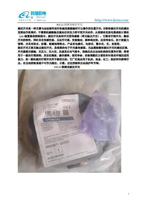
61f-11欧姆龙液位开关
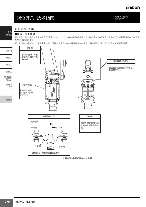
接近开关是一种无需与运动部件进行机械直接接触而可以操作的位置开关,当物体接近开关的感应面到动作距离时,不需要机械接触及施加任何压力即可使开关动作,从而驱动直流电器或给计算机(plc)装置提供控制指令。
接近开关是种开关型传感器(即无触点开关),它既有行程开关、微动开关的特性,同时具有传感性能,且动作可靠,性能稳定,频率响应快,应用寿命长,抗干扰能力强等、并具有防水、防震、耐腐蚀等特点。
产品有电感式、电容式、霍尔式、交、直流型。
接近开关又称无触点接近开关,是理想的电子开关量传感器。
当金属检测体接近开关的感应区域,开关就能无接触,无压力、无火花、迅速发出电气指令,准确反应出运动机构的位置和行程,即使用于一般的行程控制,其定位精度、操作频率、使用寿命、安装调整的方便性和对恶劣环境的适用能力,是一般机械式行程开关所不能相比的。
它广泛地应用于机床、冶金、化工、轻纺和印刷等行业。
在自动控制系统中可作为限位、计数、定位控制和自动保护环节等。
61f-11欧姆龙液位开关。
Joystick SwitchesQuality, reliability, precision Quality, reliability and precision are the hallmarks of our corporate philosophy.They represent concepts and values to which we feel totally committed. At EUCHNER, quality means that all our employees take personal respon-sibility for the company as a whole and, in particular, for their own field of work. This individual commitment to perfection results in products which are ideally tailored to the customers’needs and the requirements of the market. After all: our customers and their needs are the focus of all our efforts. Through efficient and effective use of resources, the promotion of personal initiative and courage in find-ing unusual solutions to the benefit of our customers, we ensure a high level of customer satisfaction. We familiar-ize ourselves with their needs, require-ments and products and we learn from the experiences of our cus-tomers’ own customers.EUCHNER – More than safety.Quality –made by EUCHNERMore than safety.Around the world –the Swabian specialists in motion sequence control for mechanical and sys-tems engineering.EUCHNER’s history began in 1940 with the establishment of an engineering office by Emil Euchner. Since that time, EUCHNER has been involved in the design and development of switch-gear for controlling a wide variety of motion sequences in mechanical and systems engineering. In 1953, Emil Euchner founded EUCHNER +Co., a milestone in the company’s history. In 1952, he developed the first multiple limit switch –to this day a symbol of the enterprising spirit of this family-owned company.Automation –Safety –ManMachine Today, our products range from electromechanical and electronic components to complex system solu-tions. With this wide range of products we can provide the necessary tech-nologies to offer the right solution for special requirements – regardless of whether these relate to reliable and precise positioning or to components and systems for safety engineering in the automation sector.EUCHNER products are sold through a world-wide sales network of compe-tent partners. With our closeness to the customer and the guarantee of reliable solutions throughout the globe, we enjoy the confidence of cus-tomers all over the world.Emil Euchner, the company’s founder and inventor of the multiple limit switch, circa 1928.ManMachineTable of contents Joystick switchesDesign and function4Advantages/features4Series5Series WK...Control panel installation to IEC 947-5-1 D306Series WE...Control panel installation at rear or with front plate8Series KB...Control panel installation to IEC 947-5-1 D3010Series KF...Control panel installation at rear12Series KE...Control panel installation to IEC 947-5-1 D2214Series KC...Control panel installation at rear or with front plate16Series KP...Analog JoystickControl panel installation at rear or with front plate19Universal Power Supply Unit P1/P2 for series KP joysticks22Housing HBL23Housing HBE24Front plates for housing HBL and HBE25 Technical status 09-03/06ApplicationJoystick switches or joysticks are manually actuated control devices for installation in control and front panels as well as in portable control equipment. They are used wherever motion sequences analogous to the actuation direction are controlled by hand. They are ideal for raising, lowering and triggering movements to the right and left, just to name same few possibilities.EUCHNER joysticks are used in the steel and construction industry, in machine tools, for transport and conveyor systems, in thecertification, the devices are approved for use in the ship-building industry.EUCHNER joysticks are also used for radio and cable controls, building machinery and cranes.Joysticks as control equipment in remote control devicesDesign and functionMicroswitches with a step function response are used as switching elements. Due to the intermittent control, a clear switching function is given for precise control systems. Depending on the respective application, switching elements with a power rating of between 4mA and 16A can be used. These are fixed on the mounting plate for each different series, either individually or in groups. The switching elements are actuated by the joystick being moved out of the intermediate position. The robust levers made of stainless steel are bedded with a hinged ball bearing that is fixed in a front plate.Advantages/featuresDirection of movement: Simplification of the command control station Easy mounting due to the slots in the panel Small space requirement Long service lifeRobust and lasting constructionHigh potection class: IP 65 and beyondRemote cable control for concrete pumpsModelsEUCHNER joystick switches are available in a number of different models:Series WK...(page 6)Series WE...(page 8)Series KB...(page 10)Series KF ...(page 12)Series KE...(page 14)Series KC...(page 16)Series KP...(page 19)Housing kits (from page 22)suitable for series WK, KB, KE and KFActuatingdirectionsPanel cutoutPushbutton D(with protective cap)Interlock VBellows WClamping screws forpanel thickness (1 - 8 mm)Centre position switch Z (actuated in centre position)Connection D(the connection is located on the under-side for types with 8 directions)Series WK...Control panel installation to IEC 947-5-1 D301 to 8 actuating directions with spring return operation or combinedOne changeover contact with tab connector 2.8 x 0.5 IEC 760 for each actuating direction Centre position switch Pushbutton in handleDimension drawingGermanischer LloydCertificate no. 17 041 - 00 HHOrdering codeSeriesActuating direction and switching behavior Stayput switch S (switching lever latches in selected position)Spring return switch T (switching lever returns to centre position)Options Pushbutton D Bellows W InterlockV Centre position switch Z All-round actuationRW KOrdering examples:Joystick switch series WK, actuating directions 1+3 stayput switch S,WK S13 T24 DZV actuating directions 2+4 spring return switch T, Pushbutton D, centre position switch Z,Interlock V in centre positionJoystick switch series WK, 8 switching elements as spring return switches, all-round actuation R WK T1-8 R DesignJoystick switch series WK, 4 switching elements, 2 actuating directions on request (2 switching elements per actuating direction)* Diagonal actuation of 4 adjacent switching elements is on request.Control panel installation and actuating directionsFront platePushbutton D(with protective cap)Interlock VBellows WConnection Series WE...Control panel installation at rear or with front plate1 to 8 actuating directions with stayput or spring return operation or combined One changeover contact with screw terminal for each actuating direction Centre position switch Pushbutton in handleDimension drawingGermanischer LloydCertificate no. 17 041 - 00 HHOrdering codeSeriesActuating direction and switching behavior Stayput switch S (switching lever latches in selected position)Spring return switch T (switching lever returns to centre position)Options Pushbutton D Bellows W InterlockV Centre position switch Z All-round actuation R Front plate FW EFront plate FOrdering examples:Joystick switch series WE, actuating directions 1+3 stayput switch S,WE S13 T24 DZV actuating directions 2+4 spring return switch T, Pushbutton D, centre position switch Z,Interlock V in centre positionJoystick switch series WE, 8 switching elements as spring return switches, all-round actuation R WE T1-8 R DesignJoystick switch series WE, 4 switching elements, 2 actuating directions on request (2 switching elements per actuating direction)Actuating directionsPanel cutoutInterlock V BellowsSeries KB...Control panel installation to IEC 947-5-1 D301 to 8 actuating directions, 4 switching elements. With stayput or spring return operation or combined One changeover contact with tab connector 6.3 x 0.8 IEC 760 for each actuating directionDimension drawingGermanischer LloydCertificate no. 17 041 - 00 HHOrdering codeSeriesActuating direction and switching behavior Stayput switch S (switching lever latches in selected position)Spring return switch T (switching lever returns to centre position)Options InterlockV All-round actuationR 1)1) Simultaneous actuation of 2 adjacent switching elements in diagonal actuating directions.KBOrdering examples:Joystick switch series KB, actuating directions 1+3 stayput switch S,KB S13 T24 actuating directions 2+4 spring return switch TJoystick switch series KB, actuating directions 1+3 spring return switch T,KB T13 V Interlock V in centre positionSeries KF ...Control panel installation at rear1 to 8 actuating directions, 4 switching elements. With stayput or spring return operation or combined One changeover contact with screw terminal for each actuating direction Centre position switchDimension drawingGermanischer LloydCertificate no. 17 041 - 00 HHOrdering codeSeriesActuating direction and switching behavior Stayput switch S (switching lever latches in selected position)Spring return switch T (switching lever returns to centre position)OptionsCentre position switch Z All-round actuation R 1)1) Simultaneous actuation of 2 adjacent switching elements in diagonal actuating directions.KFActuating directionsPanel cutoutOrdering examples:Joystick switch series KF, actuating directions 1+3 stayput switch S,KF S13 T24 Z actuating directions 2+4 spring return switch T, centre position switch ZJoystick switch series KF, actuating directions 1-4 spring return switch T,KF T1234 R all-round actuation RActuating directionsPanel cutoutInterlock VBellowsCentre position switch Z (actuated in centre position)Series KE...Control panel installation to IEC 947-5-1 D221 to 8 actuating directions, 4 switching elements. With stayput or spring return operation or combined One changeover contact with tab connector 2.8 x 0.5 IEC 760 for each actuating direction Centre position switchDimension drawingGermanischer LloydCertificate no. 17 041 - 00 HHOrdering codeSeriesActuating direction and switching behavior Stayput switch S (switching lever latches in selected position)Spring return switch T (switching lever returns to centre position)Options InterlockV Centre position switch Z All-round actuation R 1)1) Simultaneous actuation of 2 adjacent switching elements in diagonal actuating directions.KEOrdering examples:Joystick switch series KE, actuating directions 1+3 stayput switch S,KE S13 T24 Z actuating directions 2+4 spring return switch T, centre position switch ZJoystick switch series KE, actuating directions 1+3 spring return switch T,KE T13 V Interlock V in centre positionJoystick switch series KE, actuating directions 1-4 Spring return switch T,KE T1234 R all-round actuation RActuating directions Top view of actuating leverCentre position switch Z (actuated in centre position)Series KC...control panel installation at rear or with front plate1 to 8 actuating directions with 1 or2 switching positions for each actuating direction Switching positions as stayput or spring return operation in various combinationsCentre position switch Pushbutton in handleDimensiondrawingMain actuating directions1, 2, 3 and 4Diagonal actuating directions5, 6, 7 and 8Switching position ISwitching position IID V1)Panel cutout for assembly with bellows WX Germanischer LloydCertificate no. 17 041 - 00 HHOrdering examples: (see type code on page 18)Joystick switch series KC with tab connector, main actuating direction KCA3A5C005C0000V1 1 with 3 switching elements. As spring return switch in switching position I.As stayput switch in switching position II.Main actuating directions 2 and 4 with 2 switching elements each. As stayput switch in switchingpositions I and II. Main actuating direction 3 not used. Option V1 (mech. inter-lock from switching position I to switching position II)Joystick switch series KC with screw terminal, main actuating directions 1-4KCB4E4E4E4E5678DW as stayput switch. S with one switching element each, diagonal actuating directions 5-8,Pushbutton D, bellows W for panel mounting.Ordering codeSeriesConnection typeTab connector 2.8 x 0.5 IEC 760A Screw terminalBMain actuating direction 1Switching behavior 1)Switching function 2)Main actuating direction 2Switching behavior 1)Switching function 2)Main actuating direction 3Switching behavior 1)Switching function 2)Main actuating direction 4Switching behavior 1)Switching function 2)Diagonal actuating direction 5 3)Diagonal actuating direction 6 3)Diagonal actuating direction 7 3)Diagonal actuating direction 8 3)OptionsPushbutton in handleD Bellows for panel mounting W Bellows for surface mounting X Interlock switching position 0V0Interlock switching position I to II V1Centre position switch Z All-round actuationR1) See …Switching behavior “ table. Actuating directions which are not required must be marked with …0“.2) See …Switching functions “ table.3) Simultaneous actuation of 2 adjacent switching elements in diagonal actuating directions.K CSeries KC...Switching behavior 1)G Stayput switch (switching lever latches in selected position)Spring return switch (switching lever returns to initial position)Switching functions 2)1-23G 4G -5G G 6G I II0I II11A2F23311B 2G2311C 2H2331D 2K2331E2331Contact state in switching positionControl versionsCentre position switch Z (actuated in centre position)Series KP ...Analog Joystickcontrol panel installation at rear or with front plate Analog, proportional output signalsControl variants with 1 and 2 axes or 2 axes simultaneously Centre position switch Pushbutton in handleDimension drawing3D V1)Panel cutout for assembly with bellows WX Versions 1 = 1 axis Versions 2 = 2 axesVersions 3 = 2 axes simultaneously (only spring return version)Ordering codeSeriesControl variants 1 axis 12 axes22 axes simultaneously 3End position Stayput switchS Spring return switch TOptions PushbuttonD Bellows for panel mounting W Bellows for surface mounting X InterlockV Centre position switchZK PSeries KP ...Analog JoystickPin assignment-X (-Y)+X (+Y)+10V-10VConnection Centre position switchConnection PushbuttonInputOutput Y ± 10 V, 10 mA 0 V 0 V (GND)X± 10 V, 10 mA- V -18 V 0 V 0 V (GND)+ V+18 VOrdering example:Analog Joystick series KP for 2-axis control, limit position spring return switch T ,KP 2 TVWZmechanical interlock, V in zero position, bellows W for panel mounting,centre position switch Z in switching position zeroUniversal Power Suply Unit P1/P2 Order No. 096 645∅DTechnical dataOrdering tablePG 11073 098for heavy gauge cable gland PG 11, 6 screws for front plate attachment, cover frame PG 13.5Housing HBL, with magnetic clamp, hanging clip, fixing nut072 630for heavy gauge cable gland PG 13.5, 6 screws for front plate attachment, cover frameNote2 versions for different cable glandsPG 1119PG 13.520.8Hanging clipView AAMagnetic clampScrew depth max. 6.0 mm (valid for all fixing holes)Dimension drawing∅DTechnical dataOrdering tablePG 11048 429 for heavy gauge cable gland PG 11, 4 screws for front plate attachmentPG 13.5Housing HBE, with magnetic clamp, hanging clip, fixing nut072 626 for heavy gauge cable gland PG 13.5, 4 screws for front plate attachmentDimension drawingNotes2 versions for different cable glands View A AHanging clipMagneticclampPG 1119PG 13.520.8Technical dataOrdering tableFront plate for HBL housing, with seal 055 967Front plate for HBE housing, with seal052 954Front plates for housing HBL and HBE Front plates HBLFront plateFlat sealDimension drawingFront plates HBEFront plateFlat seal。
欧姆龙轻触式开关使用注意事项安全要点请在额定负载范围内进行使用。
若超过额定负载范围的使用,不仅会影响开关的耐久性,还可能引起发热、烧损等危险情况。
因此开关时包括瞬时电压、电流都应在额定电压、额定电流的范围内进行使用。
使用注意事项关于保存1. 保存环境· 保存产品时,为了防止端子部变色,请不要在下列条件下保存。
①高温、高湿环境下②有腐蚀性气体的环境中③阳光直射的场所2. 保存状态· 请在保留包装的状态下进行保存。
包装开封后,请尽快进行使用,并且将剩余部件在防湿、无腐蚀气体的环境中进行适当保存。
关于使用1. 操作方法不可施加强力反复操作。
在柱塞已经按下的情况下进一步加压的话,过大的负荷重量可能导致圆形板弹簧的变形,成为动作不良的原因。
特别是对横压型施加过大负载的话,铆接部会产生破损,成为开关破损的原因。
因此在安装、操作时等,请注意不要附加高于过大负荷重量(29.4N、1分钟、1次)的负荷重量。
请按柱塞可以在垂直方向动作的方向设定开关。
只按柱塞的一侧,或斜向的操作口可能导致耐久性降低2. 尘埃对策因为是没有密封构造的开关,因此请勿在有粉尘的场所进行使用。
不得不使用的情况下,应该考虑采用覆盖物等保护对策。
3. 使用环境的调查· 实际使用状态下进行设置时,请先确认其周围的设备是否会有产生腐蚀性气体的情况发生。
避免在高温、高湿、具有腐蚀性气体硫化物(H2S、SO2)、氨(NH3)、硝酸(NHO3)、氯(Cl2)等)的环境中使用。
接点接触不良、腐蚀等可能导致故障产生,使用时请注意。
接点接触不良、腐蚀等可能导致故障产生,使用时请注意。
· 使用环境中存在有硅时,可能导致接触不良的情况发生。
开关的周围存在有硅制品(硅油、硅填充材料、硅电线等)时,请通过接点保护回路进行电弧抑制或除去硅发生源等措施。
下述事项可能导致开关内部浸水、接点接触不良、腐蚀等情况的发生,导致设备故障的产生。
欧姆龙液位控制器原理
欧姆龙液位控制器是一种监测和控制液位的电子设备,其原理是通过测量液位高度,将信号传递给控制器进行逻辑处理,从而实现自动化控制的目的。
该设备采用压力传感器等传感器将液位高度转换为电信号,再经过A/D转换,将数据传递到主控芯片。
主控芯片对数据进行处理,根据预设的逻辑算法输出控制信号,控制执行机构进行操作。
在实际使用中,欧姆龙液位控制器具有多种控制方法,可根据实际需求进行配置。
例如,自动控制模式可以设置目标液位,当液位达到设定值时就停止供液或排液操作;手动控制模式可以手动调节液位高度;报警控制模式可以根据液位高度发出声光报警信号,以提示操作人员或处理异常情况。
综上所述,欧姆龙液位控制器利用传感器监测液位高度并通过逻辑算法实现对液位的自动化控制,可以广泛应用于化工、石油、食品等行业的液位监测和控制。
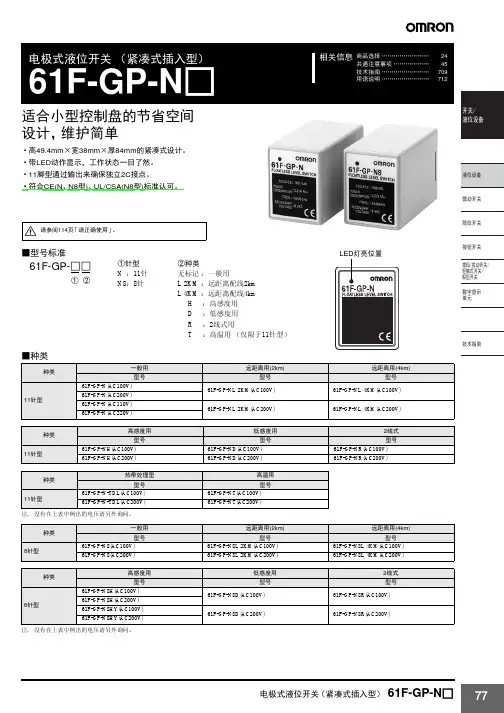
开关液位设备概要选择机型的标准故障检查液位设备Q&A关于施工资料参考电极式液位开关(61F)作为电气性液位检测方式,被广泛用于以大厦、集中住宅的上下水道为主及钢铁、食品、化学、药品、半导体等各种工业、农业水、净水场、污水处理等的液面控制。
一旦电极接触到液体,通过液体可以闭合电路(电气流通的道路),根据流过的电流检知液位控制的动作原理,是以所谓的导电性液体为控制对象的液位开关。
进行检测时,直接检测液体的电极间电阻,根据大于或小于已设定的电阻值,来判断有无液面。
■基本原理以一般接收上水道供水的情况为例来进行说明。
通常,在大厦、集中住宅区等中,一旦接水槽接收供水后,就会将水送到设置在屋顶上的高架水槽内,然后再分配到各楼层。
在高架水槽内,如果因水的消耗而导致水槽内的水位下降,通过泵从接水槽中再进行补充。
达到一定的水位后,即可停止泵了。
(参照图1)在高架水槽内,可以进行水位的控制,以保持上限和下限间的水位。
可以根据下列工作原理来进行这一水位控制。
图1. 水槽的供水控制●根据水位对泵进行ON、OFF控制(2根电极式)①如图2,电极E1未接触到液面时,电流流通的电路(E1-E3间)为开路,没有电流通过。
因此,继电器「X」不动作,继电器「X」的接点仍为“b侧”。
②如图3,电极E1接触到液面时,为电路闭合状态(液体将E1-E3间闭合),因此,继电器「X」动作,接点移动到“a侧”。
若将该继电器接点连接到接触器,则可根据液面的位置对泵进行ON、OFF控制。
但是,如图2、图3,如果仅有2根电极,电极E1附近会发生波动,导致继电器抖动。
为此,电极式液位开关有自我保持电路。
(图2、图3用于水位的报警等方面)图2 水位低时图3 水位高时●带自我保持电路的实用性水位控制(3根电极式)如图4所示,使用E1、E3电极以外的E2电极,通过a2接点连接E2、E1。
此时(前页的②)液面接触电极E1、继电器「X」动作,如果接点变为“a侧”,即使接下来液面低于E1,E2-E3间的电路也可以保持闭合状态。
商品选择 ……………………138共通注意事项 ………………146技术指南 ........................709用语说明 (743)相关信息双极双投基本开关DZ独立的2路开关用开关•电压不同的2个电路的开关、或独立的2路控制。
•安装孔尺寸、安装螺距、按钮位置和Z型相同。
请参见185页的「请正确使用」和146页的「微动开关 共通注意事项」。
型号构成■型号标准种类额定值/性能①电流额定值10:10A(AC250V)②接点间隔G :0.5mm③驱动杆的种类无标记 :针状按钮型V :摆杆型V22: 滚珠短摆杆型V2:滚珠摆杆型W :摆杆型W22:滚珠短摆杆型W2:滚珠摆杆型④接触形式1:双极双投⑤端子的种类A :焊接端子B :螺钉紧固端子DZ-10G □-1□① ② ③ ④⑤■额定值注1.左侧的数值表示稳定电流。
注2.所谓感性负载,就是功率因数为0.4以上(交流)、时间常数7ms 以下(直流)的负载。
注3.所谓电灯负载,就是有10倍的浪涌电流的负载。
注4.所谓电动机负载,就是有6倍的浪涌电流的负载。
注5.左侧额定值是在下面的条件下试验得到的数值。
(1) 环境温度:20±2℃ (2) 环境湿度:65±5%RH (3) 操作频率:20次/min额定值电压(V)非感性负载(A )感性负载(A )阻性负载电灯负载感性负载电动机负载常闭常开常闭常开常闭常开常闭常开AC 125250101021.510.76432 1.51DC814301252501010100.50.253331.51.51.56640.050.035532.52.51.50.50.250.050.03■安全规格认证额定值个别的认证型号请垂询本公司。
●UL/CSA额定值电压型号DZ-10G AC125V 10A 、 1/3HP AC250V 10A 、 1/4HPAC480V 2A DC125V 0.5A DC250V0.25A附属品(端子保护盖、驱动杆、隔板)・・・参见192~194页结构■接触形式 (2c 接点)外形尺寸(单位 :mm)■端子的种类/形状●焊接端子(-1A)●螺钉紧固端子(-1B)■外形尺寸/动作特性 型号、图解、图纸为螺钉紧固端子。
e-mail:**************For latest product manuals: Shop online at User’s Gui deLD320, LD620, LD621, LD630, LD650 Series DISPLACEMENT TRANSDUCERS***********************Servicing North America:U.S.A. Omega Engineering, Inc.Headquarters: Toll-Free: 1-800-826-6342 (USA & Canada only)Customer Service: 1-800-622-2378 (USA & Canada only)Engineering Service: 1-800-872-9436 (USA & Canada only)Tel: (203) 359-1660 Fax: (203) 359-7700e-mail:**************For Other Locations Visit /worldwideIndexSection Title1.0 Introduction .2.0 Installation2.1 Mounting the Transducer .2.2 Cores2.3 Carriers2.3.1 Guided Carriers2.3.2 Ball Tips2.3.3 Springs2.3.4 Universal Joints2.3.5 Thread Mount Option3.0 Electrical Interfaces3.1 Standard LVDT3.2 4-20MA3.3 DC Voltage3.4 Digital4.0 Conditioning5.0 MarkingThe information contained in this document is believed to be correct, but OMEGA accepts no liability for any errors it contains, and reserves the right to alter specifications without notice.Omega's new LD320, LD620, LD621, LD630 range of displacement trans-ducers forms a wide range of transducers offering measurement ranges from ±2.5 mm to ±150 mm. The LD320, LD620, LD621, LD630 offers the advantage of a shorter body than traditional displacement transducers. Furthermore, four electrical output types are provided; these are standard LVDT, 4-20 mA, isolated DC voltage and digital outputs.All models in the LD320, LD620, LD621, LD630 can be configured with guided or unguided core for frictionless operation. The wide bore to core clearance of the LD320, LD620, LD621, LD630 makes installation and alignment a very easy process. The guided versions are provided with polymer bearings for high rigidity and are available with special tips, univer-sal joint fittings and return springs. The universal joints are useful in appli-cations where lever movements induce variations in the motion straight-ness.The rugged construction of the LD320, LD620, LD621, LD630 and the options of IP65 and IP67 rating makes these transducers a cost-effective product suitable for use in harsh environments.GENERAL SPECIFICATIONStorage Temperature LVDT Variants-40 °C to +120 °C 4-20 mA, DC and Digital Variants-20 °C to +85 °COperating Temperature LVDT Variants-40 °C to +120 °C 4-20 mA and DC Variants0 °C to +65 °C Digital variants (Transducer only)-40 °C to +120 CLinearity0.2% FSOFor full specification please refer to the Product Datasheet or catalog.Typical Mechanical Configurations2.1: Mounting the TransducerLVDT based transducers are a reliable and proven technology that iswell established in all areas of manufacturing and control industries.The majority of the associated problems experienced with their appli-cation and use are totally avoidable, particularly if sufficient thought is given during the initial design stages of equipment to the positioning and clamping methods employed for these feedback elements.LVDT’s, being of inductive nature, are susceptible to some degree to theThe LD320, LD620, LD621, LD630, LD650, transducers contain an inte-gral magnetic screen that reduces these effects. However, the transducer should be positioned well away from electric motors, relays and permanent magnets. If this is not possible checks should be made on the influence of such items.Clamping of the coil assembly should be carefully considered. Some example methods are shown below. Ideally the body of the transducers should be clamped centrally in a pinch or yoke type clamp, manufactured from a low conductivity, non-magnetic material.Irrespective of clamping method, care must be taken not to over-tighten retaining screws as distortion of the body may prove damaging to the integrity of the transducer and adversely affect the geometry of the instal-lation.If the LVDT is to be mounted on equipment subject to high ”g” then, dependent on the direction of these forces, it may be advantageous to consider end to end clamping in preference to over body clamping.For Universal Joint fittings maximum tightening torque on the ball = 2.5 Nm.2.2: CoresThe standard core supplied is a ∅6.35 mm Core with M4 x 0.7 x 12 mm female thread at both ends for mounting onto a carrier. The magnetic core has been manufactured to achieve optimum performance and any sub-sequent handling of the core which results in stress being imparted will render the calibration void. This includes over-tightening of the core during installation onto its carrier. Hand tightening and retention by meansof a suitable thread locking anaerobic retaineris the recommended procedure.2.3: CarriersA standard length carrier is available for each model of transducer, manu-factured from 316 stainless steel and incorporating an M4 x 0.7 x 10 mm long male thread for attachment to the standard core and an M6 x 1.0 x 17 mm male thread for attachment to the fixture.2.3.1: Guided CarriersMounting: Normal mounting methods apply (see Installation). Careful con-sideration should be given to alignment; the carrier must be able to move freely within the transducer core. Side force should be kept to a minimal level.Maintenance: Check for free movement of the carrier when in the vertical plane. The polymer guide bearing is maintenance free.2.3.2: Ball TipsThis option is for use with the Guided Carrier andis attached via an adapter fitted to the threaded end of the core carrier. Side forces that may exert undue pressure and flex the carrier must be avoided.2.3.3: SpringsA spring may be fitted externally in conjunction with a guided carrier and also with a ball tip.2.3.4: Universal JointsMounting: All LD320, LD620, LD621, LD630 transducers up to 300 mm total measurement range (±150 mm) may be mounted in any axis; it is recommended that the rear rod end bearing (near cable exit) is mounted on the static component. (The larger transducers, because of the increase in weight, may exhibit bowing of the carrier and therefore mounting in the horizontal plane should either be avoided or additional support given to the body. This option is used with the guided core.)Maintenance: Periodic inspection of locking screws and nuts etc. is advis-able depending upon the Customer’s application. Rod end bearings should be able to move freely and have minimal side play.2.3.5: Thread Mount Option - LD650 Series3.0: Electrical Interfaces3.1: Standard LVDT The LD320, LVDT output transducer is designed to operate with an exci-tation voltage of 3 ± 1 V rms, an excitation frequency of 5 ± 0.5 kHz into a 100 k Ω load as detailed below. Operation in different configurations may mean the optimum performance is degraded.Standard LVDT Connector 5 pin 240º DINThe LD320 range of LVDT transducers operate on the principal that move-ment of a core inside the transducer body is detected by a differential change in output on two secondary coils, the primary coil(s) being energized by an appropriate AC excitation signal. With the core in a central position, the coupling from the primary to each secondary is equal and opposite and therefore cancel out, thus the resultant output voltage is zero. As the core is displaced further into one secondary, its voltage increases proportionally and the other secondary voltage decreases hence the output changes in magnitude and phase in proportion to movement in either direction from null.The red and white connections are in phase for inward movement (i.e. towards the cable end).The output signal depends on both core movement and energization voltage and is expressed as a sensitivity in mV output / V energizing/ mm travel.White 3.2: 4-20 MA The LD630 and LD650 are configured as a two wire 4-20 mA loop device, the transducer provides a current between 4 mA (fully out) and 20 mA (fully in). The transducer requires an excitation voltage between 10 VDC Note: 4-20 mA products are designed to operate with a maximum loop resistance of 600 W.3.3: DC Voltage The LD620 and LD621 can be configured to provide a DC voltage output as shown below;Measurement RangeOutput Output 0-d mm0-10 VDC -d/2 to +d/2 mm -5 VDCto +5 VDCThe transducer requires an excitation voltage between 10 VDC and 30 VDC.The transducer output is electrically isolated from the input supply.Note: to achieve calibrated accuracy the load must be 10 k W between Yellow and Green,3.4: DIGITAL Digital versions of the LD640 transducers are supplied with an integral PIE module.This module is fully compatible with LDN232. For details see Digital Probe User Leaflet.3.0: Electrical Interfaces (continued)4.0: ConditioningThe 4-20 mA and DC output version of the transducer require no signal conditioning other than being connected to an appropriate receiver such as a voltmeter, A/D converter or current meter.LVDT transducers usually require the signal to be conditioned either by end user amplifiers or with Omega conditioning circuits. Information on these products can be obtained from original supplier.5.0: MarkingProducts with integrated electronics are CE marked.Digital probes are CE marked.WARRANTY/DISCLAIMEROMEGA ENGINEERING, INC. warrants this unit to be free of defects in materials and workmanship for a period of 13 months from date of purchase. OMEGA’s WARRANTY adds an additional one (1) month grace period to the normal one (1) year product warranty to cover handling and shipping time. This ensures that OMEGA’s customers receive maximum coverage on each product.If the unit malfunctions, it must be returned to the factory for evaluation. OMEGA’s Customer Service Department will issue an Authorized Return (AR) number immediately upon phone or written request. Upon examination by OMEGA, if the unit is found to be defective, it will be repaired or replaced at no charge. OMEGA’s WARRANTY does not apply to defects resulting from any action of the purchaser, including but not limited to mishandling, improper interfacing, operation outside of design limits, improper repair, or unauthorized modification. This WARRANTY is VOID if the unit shows evidence of having been tampered with or shows evidence of having been damaged as a result of excessive corrosion; or current, heat, moisture or vibration; improper specification; misapplication; misuse or other operating conditions outside of OMEGA’s control. Components in which wear is not warranted, include but are not limited to contact points, fuses, and triacs.OMEGA is pleased to offer suggestions on the use of its various products. However, OMEGA neither assumes responsibility for any omissions or errors nor assumes liability for any damages that result from the use of its products in accordance with information provided by OMEGA, either verbal or written. OMEGA warrants only that the parts manufactured by the company will be as specified and free of defects. OMEGA MAKES NO OTHER WARRANTIES OR REPRESENTATIONS OF ANY KIND WHATSOEVER, EXPRESSED OR IMPLIED, EXCEPT THAT OF TITLE, AND ALL IMPLIED WARRANTIES INCLUDING ANY WARRANTY OF MERCHANTABILITY AND FITNESS FOR A PARTICULAR PURPOSE ARE HEREBY DISCLAIMED. LIMITATION OF LIABILITY: The remedies of purchaser set forth herein are exclusive, and the total liability of OMEGA with respect to this order, whether based on contract, warranty, negligence, indemnification, strict liability or otherwise, shall not exceed the purchase price of the component upon which liability is based. In no event shall OMEGA be liable for consequential, incidental or special damages.CONDITIONS: Equipment sold by OMEGA is not intended to be used, nor shall it be used: (1) as a “Basic Component” under 10 CFR 21 (NRC), used in or with any nuclear installation or activity; or (2) in medical applications or used on humans. Should any Product(s) be used in or with any nuclear installation or activity, medical application, used on humans, or misused in any way, OMEGA assumes no responsibility as set forth in our basic WARRANTY / DISCLAIMER language, and, additionally, purchaser will indemnify OMEGA and hold OMEGA harmless from any liability or damage whatsoever arising out of the use of the Product(s) in such a manner.RETURN REQUESTS/INQUIRIESDirect all warranty and repair requests/inquiries to the OMEGA Customer Service Department. BEFORE RETURNING ANY PRODUCT(S) TO OMEGA, PURCHASER MUST OBTAIN ANAUTHORIZED RETURN (AR) NUMBER FROM OMEGA’S CUSTOMER SERVICE DEPARTMENT (IN ORDER TO AVOID PROCESSING DELAYS). The assigned AR number should then be marked on the outside of the return package and on any correspondence.The purchaser is responsible for shipping charges, freight, insurance and proper packaging to prevent breakage in transit.OMEGA’s policy is to make running changes, not model changes, whenever an improvement is possible. This affords our customers the latest in technology and engineering.OMEGA is a trademark of OMEGA ENGINEERING, INC.© Copyright 2017 OMEGA ENGINEERING, INC. All rights reserved. This document may not be copied, photocopied, repro-duced, translated, or reduced to any electronic medium or machine-readable form, in whole or in part, without the prior written consent of OMEGA ENGINEERING, INC.FOR WARRANTY RETURNS, please have the following information available BEFORE contacting OMEGA:1. Purchase Order number under which the product was PURCHASED,2. M odel and serial number of the product under warranty, and3. R epair instructions and/or specific problems relative to the product.FOR NON-WARRANTY REPAIRS, consult OMEGA for current repair charges. Have the following information available BEFORE contacting OMEGA:1. P urchase Order number to cover the COST of the repair,2. Model and serial number of the product, and 3. Repair instructions and/or specific problems relative to the product.Where Do I Find Everything I Need for Process Measurement and Control?OMEGA…Of Course!Shop online at TEMPERATUREM U Thermocouple, RTD & Thermistor Probes, Connectors, Panels & AssembliesM U Wire: Thermocouple, RTD & ThermistorM U Calibrators & Ice Point ReferencesM U Recorders, Controllers & Process MonitorsM U Infrared PyrometersPRESSURE, STRAIN AND FORCEM U Transducers & Strain GagesM U Load Cells & Pressure GagesM U Displacement TransducersM U Instrumentation & AccessoriesFLOW/LEVELM U Rotameters, Gas Mass Flowmeters & Flow ComputersM U Air Velocity IndicatorsM U Turbine/Paddlewheel SystemsM U Totalizers & Batch ControllerspH/CONDUCTIVITYM U pH Electrodes, Testers & AccessoriesM U Benchtop/Laboratory MetersM U Controllers, Calibrators, Simulators & PumpsM U Industrial pH & Conductivity EquipmentDATA ACQUISITIONM U Communications-Based Acquisition SystemsM U Data Logging SystemsM U Wireless Sensors, Transmitters, & ReceiversM U Signal ConditionersM U Data Acquisition SoftwareHEATERSM U Heating CableM U Cartridge & Strip HeatersM U Immersion & Band HeatersM U Flexible HeatersM U Laboratory HeatersENVIRONMENTALMONITORING AND CONTROLM U Metering & Control InstrumentationM U RefractometersM U Pumps & TubingM U Air, Soil & Water MonitorsM U Industrial Water & Wastewater TreatmentM U pH, Conductivity & Dissolved Oxygen Instruments M4345/1217。
K用于小型储罐应用的非接触式液位控制器LVCN414系列是非接触式超声波液位控制器和变送器,提供可靠的低成本、高性能小储罐液体处理解决方案。
LVCN414目标用途是安装在滑道、工具或机械上的小型储罐中的过程、控制和化学品投送应用。
LVCN414具有高度的灵活性,适合针对浮子、传导和压力传感器的系统集成或改造而设计的应用, 可通过USB 连接及Windows XP 兼容软件(可从/ftp 下载) 轻松配置。
L VCN414提供高精度和准确度, 支持实时/随时测量,降低作业成本,并提高生产率。
过程或控制自动化应用的液位指示可通过现场显示屏或远程PLC 进行监视。
L VCN414是一款全面的小储罐液位控制和测量解决方案。
LVCN414系列LVCN414-B , 图片小于实际尺寸。
LVCN414-USB (需要一个), 图片小于实际尺寸U 适合连续及开关应用的 可靠、非接触式替代选择U 紧凑型传感器,非常适合小型储罐应用U 用于泵和报警的控制/开关功能U 用于腐蚀性液体介质的PVDF 传感器U 通过USB 连接和从/ftp 下载的免费软件可轻松安装和设置U 提供电流、电压和仅继 电器型号LVCN414-V-BLVCN414-I-B LVCN414-R-B用于编程的配置软件可从/ftp 免费下载订购示例: LVCN414, 带继电器和USB 连接器的液位变送器,1 NPT 1.2 m (4')量程。
规格量程: 1.25 m (49.2")精度: 3 mm (0.125")分辨率: 0.5 mm (0.019")射束宽度: 5 cm (2")死区: 5 cm (2")电源电压: 24 Vdc ,12 ~ 24 Vdc/ Vac (LVCN414-R 型号)环路电阻: 最大400功耗: 0.5 W信号输出(LVCN414和LVCN414-I ): 4 ~ 20 mA ,2线(采用回路供电时) 信号输出(LVCN414-V): 0 ~ 5 Vdc 、0 ~ 10 Vdc 或 976 ~ 2000 Hz接触类型(LVCN414和LVCN414-R ): (4)个SPST 继电器1A模拟故障安全(LVCN414、LVCN414-I 和LVCN414-V ):满、空或保持最后状态继电器故障安全(LVCN414和LVCN414-R ):断电: 保持最后状态通电: 开、闭或保持最后状态滞后(LVCN414和LVCN414-R ): 可选 配置: 通过从/ftp 下载的 USB/PC Windows ® 软件进行配置温度补偿: 自动全量程温度: -35 ~ 60°C (-31 ~ 140°F)外壳: NEMA 6P (IP68)外壳材质: PC/ABS FR 耐扭电缆材料: Santoprene 传感器材质: PVDF 电缆长度: 1.2 m (4')电缆护套材质: PVC 过程安装件: 1 NPT 安装垫圈: 氟橡胶类别: 通用 认证: CE。
开关液位设备概要选择机型的标准故障检查液位设备Q&A关于施工资料参考电极式液位开关(61F)作为电气性液位检测方式,被广泛用于以大厦、集中住宅的上下水道为主及钢铁、食品、化学、药品、半导体等各种工业、农业水、净水场、污水处理等的液面控制。
一旦电极接触到液体,通过液体可以闭合电路(电气流通的道路),根据流过的电流检知液位控制的动作原理,是以所谓的导电性液体为控制对象的液位开关。
进行检测时,直接检测液体的电极间电阻,根据大于或小于已设定的电阻值,来判断有无液面。
■基本原理以一般接收上水道供水的情况为例来进行说明。
通常,在大厦、集中住宅区等中,一旦接水槽接收供水后,就会将水送到设置在屋顶上的高架水槽内,然后再分配到各楼层。
在高架水槽内,如果因水的消耗而导致水槽内的水位下降,通过泵从接水槽中再进行补充。
达到一定的水位后,即可停止泵了。
(参照图1)在高架水槽内,可以进行水位的控制,以保持上限和下限间的水位。
可以根据下列工作原理来进行这一水位控制。
图1. 水槽的供水控制●根据水位对泵进行ON、OFF控制(2根电极式)①如图2,电极E1未接触到液面时,电流流通的电路(E1-E3间)为开路,没有电流通过。
因此,继电器「X」不动作,继电器「X」的接点仍为“b侧”。
②如图3,电极E1接触到液面时,为电路闭合状态(液体将E1-E3间闭合),因此,继电器「X」动作,接点移动到“a侧”。
若将该继电器接点连接到接触器,则可根据液面的位置对泵进行ON、OFF控制。
但是,如图2、图3,如果仅有2根电极,电极E1附近会发生波动,导致继电器抖动。
为此,电极式液位开关有自我保持电路。
(图2、图3用于水位的报警等方面)图2 水位低时图3 水位高时●带自我保持电路的实用性水位控制(3根电极式)如图4所示,使用E1、E3电极以外的E2电极,通过a2接点连接E2、E1。
此时(前页的②)液面接触电极E1、继电器「X」动作,如果接点变为“a侧”,即使接下来液面低于E1,E2-E3间的电路也可以保持闭合状态。
这种E2电极和接点构成的电路称为自我保持电路。
如果液面低于E2,为使电路再次打开、继电器「X」复位到“b侧”,可以在E1-E2间对继电器[X]进行ON、OFF控制。
图5表示该动作的时间图。
由于这种动作方式简单,除了液位控制,电极式液位开关还应用于接触开关、漏水检测器、进行大小判别的传感器等。
图4 自我保持电路图5时间图请注意:在油之类不能通电的液体中,不能根据本方式进行液面控制。
●净水用于饮用的净化水,一般指送到家庭的水、自来水。
使用泵送到指定地方的水。
多为抽取自来水。
而净化槽,是指净化污水的槽,不要混淆。
●使用水有目的地储放的水,多为与自来水有相同灵敏度的水。
如防火用水等。
. ●污水是流向下水道前的水,一般指厕所的排水。
[参考]家庭、工厂的排水中含有固体物、浮游物,且液体也是低电阻,因此必须考虑电极的设置。
●上水(自来水)[参考]基本上与净水的意思相同。
对下水来说是上水,在水道局也有上水道和下水道之分。
在水道局,净化前的水也称为上水,比净水意思更广。
●下水(下水道)与其说是水的种类,还不如说是污水流动的体系。
发达国家的下水道是很完善的。
在一些大城市,下水道完善的地方较多,这种情况下,无需净化槽,直接流出污水排杂槽。
另外,也有一些地方没有设置污水排杂槽,而往往会直接将流出污水的管子连接到下水道。
●雨水61F-GN-NH3指积留在水坑等地方的雨水。
与净水相比,电阻稍高。
●涌出水指像泉水一样涌出的水。
●循环水与雨水相同,电阻稍高●抽水使用泵送到指定地方的水。
多为抽取自来水。
●使用水有目的地储放的水,多为与自来水有相同灵敏度的水。
如防火用水等。
●离子交换水是指除去离子成分的水。
除去离子成分的方法不是蒸馏,因此是高电阻。
[参考]一般使用的水为动作电阻200kΩ更有时使用61F-GP-NH3 ,但使用除去离子成分的方法后,电阻值会提高。
(纯水)●蒸馏水一般为收集的水蒸汽,但电阻比纯水低。
[参考]可以用高灵敏度用的61F。
●循环水锅炉蒸汽的循环水。
在管道中,指蒸汽成为水滴形成的水。
●纯水指不含不纯物质的水。
事例如下,从200kΩ·cm开始,高达18MΩ·cm位,必须使用超高灵敏度的61F 。
[参考]为纯水时,为确保水的纯度,应使用钛电极。
●冷凝水指蒸汽涡轮、锅炉等的冷却水。
指为使锅炉的热水保持一定的纯度而排放出来的水。
用于存放这种水的容器,其电阻应比一般用的稍低。
水槽·池●接水槽在大厦、公寓大楼等高层住宅屋顶上有高架水槽的地方,一旦水槽里储有水,就会在高架水槽内用泵将水吸上来。
这个水槽称为接水的水槽。
一般设置在地下室或一层。
[参考]在本样本目录中作为一般性的供水源,但在大厦以外的情况下不称为接水槽。
它多与消防用的消防栓共用,选择电极的长度时必须考虑这些。
接水槽本身的液位控制,通过另外的61F 或球形旋塞来进行。
(也有和高架水槽用的61F的电极一起接入的情况)在稍微大点的大厦、公寓大楼中使用61F-G4N。
●高架水槽指设置在大厦、公寓大楼等高层住宅屋顶上的,利用高度来提供水槽。
[参考]从接水槽61F-G4N或61F-GIN 等自动地将水泵上来。
最近引进了直接施加压力进行送水的系统(压送式),也可用于?不带高架水槽的大厦,在停电、天灾等情况下,人们重新认识了储水罐的作用。
指相对于水源地,将从水源地分配到的暂时性蓄水,提供到住宅的池。
设于分支用的小型水源地。
●污水排杂槽在下水道完善的城市中,作为净化水槽的替代品,积蓄来自厕所的污水和厨房的排水。
[参考]对于普通的公寓大楼等,是从污水管道直接流到下水道,但是对于有地下室的大楼,必须到下水道用泵将水吸上来。
为此,必须在地下设置积蓄污水的槽。
此时,油、固体物会直接进入,因此,设置电极时,必须每隔1 极设置,并防止电极间的短路。
●水源池指水道局为给居民用的水道供水而造的池等。
无论何种形式下,从各种水源将水送到这里,通过净化装置为市民供水。
[参考]水源池通常应保持一定的水位,多使用61F,继电器和电极间的布线非常长的地方也有很多。
除公共场所以外,也有一些私设水源地的地方●净化槽收集厕所的排水,暂且在这里进行净化。
即在无固体物的状态下将其排放到其他地方。
[参考]由于净化槽中环境为弱碱,因此必须注意绝缘。
在下水道完善的城市,大厦等无需净化槽的地方也较多,而将其转移到污水排杂槽。
规格●动作电阻指61F本体进行动作所需的电极间的电阻值,如果液体或固体的电极间电阻值低于该值,就一定会动作。
[参考]即使在该值很高不易导通的液体中,也能动作,这时需要高灵敏度。
●电极间电阻大致与动作电阻相同。
从61F的输入(电极)到61F本体有动作电阻、布线有可能是长距离,因此不一定相同,但一般情况下认为是相同也是没问题的。
●导电率(西门子:S)表示液体导电度的单位。
最近用微西门子(μS)来表示(以前是姆欧:)。
由于是电阻的倒数,值越小电阻就会变得越高,因此必须为高灵敏度。
1μS/cm →1MΩ·cm2μS/cm → 500kΩ·cm10μS/cm → 100kΩ·cm●自我保持如果继电器工作,记忆保持这一状态的功能就是自我保持。
为61F-GN时,E2电极就会变为自我保持用。
根据具备的自我保持功能考虑控制的幅度,另外,可防止由于液面的波动引起的继电器抖动。
●接点容量(输出)61F可开关负载容量。
●复位电阻61F本体进行复位所需的电极间的电阻值,如果高出该值,61F就会复位。
[参考]一般情况下,如果没有液体,电阻将会变为无穷大,但是,由于电极保持器、分离器等上面附着了液体,因此不能马上变为无穷大。
61F中,多数情况下该值较为重要(根据布线的不同,还会影响到漏电流),低灵敏度用、远距离用就是因为这一原因。
●固有电阻表示液体电流流动的难易度,单位为kΩ·cm.为电导率成倒数的关系。
(请注意,与动作电阻不同)通过液体使电气在电极棒间的无数线路流通。
固有电阻表示这一电气流通的难易度。
由于固有电阻根据电极的设置条件、浸水长度而有所不同,因此,实际设备的动作是根据电极的间隔、表面积(浸水长度)确定的。
要求出电极间电阻较困难,因此以固有电阻为标准。
●动作电压指61F动作所需的电源电压。
61F的动作电压为额定电压的85%以上。
因此,注意不要使电源电压在85%以下。
●最小适用负载电子电路等非常小的负载(微小负载)的可开关界限的标准。
●接点构成指接点的接触机构。
[参考]●负载分为以下3种⑴阻性负载指如果施加电压,就会一直流通相同值电流的负载,如加热器。
⑵感性负载指含有电感的负载,如电机、螺线管等。
⑶容性负载指含有电抗的负载,如电容器等。
[参考]●冲击电流闭合接点的瞬间,大于稳定状态的过渡性流入电流。
●预动作方式61F 本体施加控制电源的同时,内置继电器动作,电极间流入电流就会复位的方式。
●正动作方式在电极间流入电流后,内置继电器进行动作的方式。
注. 高灵敏度以外采用正动作方式。
但61F-G□NH也采用正动作方式●开关频度单位时间的动作次数。
如,次/hour 。
动作●2线式(带R)电极和61F本体间,可以省略1根电线进行布线的方式,液位电极、自我保持电极、接地电极3线当中,省略自我保持电极进行布线的方式。
而自我保持电极是必须的。
这种情况下,必须选择型号中带R型的61F 本体(继电器单元也一样)、电极保持器,并加上(电阻)1W 6.8kΩ。
[参考]*1. 表示兼具防止泵空转的供水自动运转。
*2. 表示兼具异常缺水报警的供水自动运转时。
●3线式相对于2线式的称呼。
(61F的基本方式为3线式)●防止空转用泵将水吸上来时,在大厦、公寓大楼等高层大楼中,可以通过接水槽吸到高架水槽中。
此时,如果接水槽内没有了水,并继续空转,则会吸进空气,可能会导致电机过热并烧损。
为了避免这种情况,必须在水位降到一定液位以下时,将泵强制停止,即可防止马达烧损。
61F-G1N 、-G1 以及61F-G4N 、-G4 均具备该功能。
●交互运转用电机将水吸上来时,在达到某种规模的地方,备有预备电机。
如果不使用电机,可能会导致其生锈老化;而如果连续使用,其产生的热量也会导致其老化,因此,通过2台电机交互使用,就会延长电机的使用寿命,即使1台出了故障,还有1台也可以运转。
[参考] (必须配备外部切换开关)61F-AN 、-APN2带有该功能。
选择机型的标准■分类(供参考用)●根据液体来分类的示例●根据电极部安装来分类的示例●根据电极部安装来分类的示例■选择61F本体的标准●固有电阻和机型选择的标准使用一般用途的可控制液体的固有电阻时,用PS-3S电极保持器、浸水长度为30mm以下的情况下,其界限为30kΩ·cm。