阿拉丁V5操作手册
- 格式:pdf
- 大小:58.32 MB
- 文档页数:82
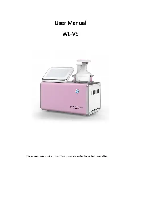
User ManualWL-V5The company reserves the right of final interpretation for the content hereinafter.Table of ContentsPart IProduct OverviewTheoriesProduct DisplayInterface DisplayDetailed Operation:Handle(A)Detailed Operation:Handle(B)Part II Treatment MethodsSafety PrecautionsDos and Dont’sTroubleshootingMachine MaintenancePacking ListWarrantyPart IProduct OverviewV5is a new modal integrating HIFU and RF technology,which helps achieve body shaping and body contouring.Please read this manual carefully before use and utilize this product only for its intended use as described in this manual. TheoriesHIFUHIFU transforms condensed thermal points through source energy and reach deep into subcutaneous fat layers to destroy and reduce the excess fat cells,stimulate collagen contraction and thickening,at the same time stimulate the elastic fiber so that redundant adipose cells are disintegrated into triglyceride that later can be excreted through body metabolism and eventually achieves the body shaping effect. RFRF technology is adopted to travel thorough the epidermis and reach the subcutaneous tissues directly,so as to vibrate the skin and the water molecules in the subcutaneous tissues,so as to accelerate the generation of heat by tissue friction.The increase of temperature promotes the catabolic metabolism of subcutaneous fat, stimulates the proliferation and reorganization of collagen and elastic fibers,and achieves the effects of skin firming,shaping and lifting.Product DisplayProduct Modal V5Power160WModal Voltage220VWorking Voltage36V Probe2pcs19kgPackage Size52*46*28cm Weight(package included) Interface Display(Handle A)Detailed Operation:Handle(A)1.Clean the treatment area before use;2.Connect the power cord and press the round switch button at the top of thescreen to turn on the device;3.Click‘enter’to go to the interface above;4.Click‘handle(A)’to go to the interface of the larger probe;HIFU energy is0-10,RF energy is0-10,click on to increase or decrease the energy level; It is advised to start with level1for first-time users,and increase accordingly based on one’s comfort level;heat or stinging sensation during the process is within the normal range;5.Click‘time’to set the working time.For example,the recommended operation time for waist and abdomen is30-45minutes;Adjust working time according to the size of the treatment area;6.After setting the working time and energy,click‘PAUSE’.There is a round button on the handle to start and stop.Press the button on the handle and you will hear a beep sound to start and press the button on the handle to stop the treatment. Interface Display(Handle B)Detailed Operation:Handle(B)1.Click‘enter’to go to the interface above;2.Click‘handle(B)’to go to the interface of the larger probe;HIFU energy is0-10,RF energy is0-10,click on to increase or decrease the energy level; It is advised to start with level1for first-time users,and increase accordingly based on one’s comfort level;heat or stinging sensation during the process is within the normal range;3.Click‘time’to set the working time.For example,the recommended operation time for waist and abdomen is30-45minutes;Adjust working timeaccording to the size of the treatment area;4.After setting the working time and energy,click ‘PAUSE’.There is a roundbutton on the handle to start and stop.Press the button on the handle and you will hear a beep sound to start and press the button on the handle to stop the treatment.5.Clean the surface of the probe after treatment and apply maintenance product.Part IITreatment Methods1.Mark the treatment area and measure the marked site before the operation;2.Apply the couplant on the treatment area and the probe.AbdomenTreatmentLegTreatmentMove the probe in circular motions firstly from upper side of the waist to the navel,and then from the middle side of the waist to the navel,then the lower side of the waist to the navel,and finally from navel to groin;It is recommended to move the probe at a constant speed and even motion;Set the working time according to the user’s degree of skin relaxation.Firstly move the probe from the bottom to the top in circular motions,then popliteal fossa to the end of thigh,then from knee to groin;Set the working time according to the user’s degree of skin relaxation.BackTreatmentButtocksTreatmentMove the probe upwards and then lift towards the underarm from the outer side of the arm;Set the working time according to the user’s degree of skin relaxation.Move the probe from the lower side of the cervical spine to the lower back;Move the probe back and forth to cover the entire back.Move the probe from the end of the thigh and pushes upwards.Safety Precautions1.It is not recommended to operate during menstruation;2.It is not recommended to operate during pregnancy or one month after child delivery;3.It is not recommended to operate around metal,plastic,silicon infills;4.It is not applicable to those embedded with hearing aids,pacemakers and other medical electronic devices;5.It is not applicable to those with severe ‘3H’(hypertension,hyperglycemia,hyperlipidemia),metal illness,etc;6.It is not applicable to those with abnormal fat metabolism,including severe hyperlipidemia or severe fatty liver;7.It is not applicable to those with skin allergy or inflammation or those with infectious skin diseases;8.It is not applicable to those with long-term continuous use of anticoagulant polymerization drugs;For example:non-steroidal anti-inflammatory drugs or oral contraceptives,or those with long-term use of hormone drugs;9.It is not applicable to children under the age of 12and those with irrational expectations of cosmetic effects;Dos &Don’ts1.Hot bath in high temperature is not recommended within 4hours after the treatment;2.After operation,it is recommended to keep drinking water every day (2000cc);3.Keep doing at least 10-15minutes of exercise a day,preferably jogging or aerobic exercise and stay in a good mood;4.Diet should be light;Do not overeat and try to keep a nutritional and balanced diet;Place the probe above the hip bone,and space one fist above the vertebrae;Follow the arrows to conduct the treatment.5.Keep a balance between work and rest;Do not drink excessively,eat late snacks, etc.TroubleshootingProblem SolutionNo response after plugged in First,check whether the line plug ispowered on and replace the outlet orsocketCan’t get to the interface after turning on the device Turn off and restart,or loosen the screws on the screenNote:The device is a precision electronic product.It is prohibited to use in a humid environment,such as bath room;Once flooded with water,please stop using immediately and return it to the factory for repair!Packing List1×Main Machine1×Power Cord1×Handle A1×Handle BMachine Maintenancee a three-prong plug with grounding pin,and ensure that the power socket is well grounded;2.Ensure that the voltage of the device is appropriate.If the voltage of the local power supply is unstable,we recommend that users increase to the matching power voltage;3.The instrument shall not be placed in a humid place or near the water source,nor shall it be directly exposed to the sunlight;4.The instrument should not be too close to the strong pyrogen or strong radiation source(disinfection cabinet,induction cooker,microwave oven,etc.),which will affect the normal use of the device;5.Always use the original qualified parts provided by the manufacturer;6.After each operation,the operating handle shall be cleaned,disinfected and properly stored;7.If the instrument is not in use,please turn off the power supply,pull out the plug and properly store all kinds of accessories.WarrantyDear users:Thank you for your support and trust!V5warrants the device for a period of ONE YEAR after the original date of purchase, against defects due to faulty workmanship or materials.It is free of charge to repair during the warranty period.(Note:Repair costs shall be borne by the user for malfunction caused by the user).Terms&Conditions1.One year warranty starts from the date of purchase;2.For any warranty claim,warranty card and the record of purchase must be provided;3.Repair and replacement of the device components shall be charged with the amount listed as the replacement price if the warranty expires;4.The customer shall NOT be entitled to any claim under the warranty to repair or replace the product under the following circumstances:4.1.Damage or malfunction caused by opening or disassembling the device;4.2.Failure to provide provide the warranty card and the record of purchase.ModalDate of PurchaseNameContact Info.Malfunction Description。
SKT-V5数控机床说明书一、方式译码开关:1、EDIT程序编辑方式,编辑一个已存储的程序。
2、AUTO程序自动运行方式,自动运行一个已存储的程序。
3、MDI手动数据输入方式,直接运行手动输入的程序。
4、INC增量进给方式5、HANDLE手摇脉冲方式,使用手轮,步进的值由手轮开关来选择。
6、JOG手动进给方式,使用点动健或其他手动开关。
7、ZRN回零方式,手动返回参考点。
二、CRT、MDI控制面板:1、POS:显示坐标的位置。
2、PRGRM:显示程序的内容。
3、MENU、OFSET:显示或输入刀具偏置量和磨耗值。
4、DGNOS/PQRAM:显示诊断数据或进行参数设置。
5、OPRALARM:显示报警和用户提示信息。
6、AUXGRAPH:显示或输入设定,选择图形模拟方式。
7、PAGE↑↓:按该键可以进行显示器的翻页。
要进行操作必须按相应的上述6个功能键。
8、INPUT:数据的输入键。
9、START:程序启动键或数据的输出键。
三、机床操作面板:1、ST启动开关;SP停止开关。
2、KEY开关是写保护开关。
3、TRST开关是手动换刀开关。
4、ON水泵启动开关、OFF水泵停止开关。
5、NOR开关:是手动主轴正转开关。
6、REV开关:是手动主轴反转开关。
7、STOP是手动主轴停止开关。
8、DRN:空运行开关。
9、BDT:程序跳转开关。
10、SBK:程序单段开关。
进给倍率开关。
急停按钮开关。
F3------隐藏目录树F1------实时帮助ctrl+z---------撤消ctrl+y--------redoctrl+n--------新建ctrl+o--------打开ctrl+鼠标中键视图放大缩小alt+鼠标中键视图平移alt+鼠标左键+鼠标中键视图旋转Alt + Enter = 性质shift 加中键出现红色方块后拖拉即可快速缩放大小这非常好用先按CTRL 再加中键是放大缩小先按中键再加CTRL 是是对象旋转而对象旋转时外面会出现红色的圆形区域在圆形区域内是XYZ轴的任意旋转而在圆形区域外是针对Z轴的特定旋转用鼠标指向某个封闭空心实体外表面,然后按键盘方向键,就可以选到内表面!ctrl+F11,出现物体选择器。
Ctrl + Page up -------zoom inCtrl + Page down ------zoom outAlt + shift + 上下左右箭头----rotateCtrl +上下左右箭头----panCtrl +shift + 左右箭头——————rotateshift+F3 --work on specification treeshift +F2--specification tree overview (在工具拦)MB3+Customize.......可自定义在自由造型与A级曲面中:F5--调出“操作平面对话框”(对“由N点成面”等命令尤为重要)控制金钱,可以得到财富;控制餐饮,可以得到健康;控制情绪,可以得到快乐;控制感情,可以得到幸福。
学会控制,可以得到更多。
零件设计PDG:Part Design装配设计ASD:Assembly Design交互式工程绘图IDR:Interactive Drafting创成式工程绘图GDR:Generative Drafting结构设计STD:Structure Design线架和曲面设计WSF:Wireframe and Surface钣金设计SMD:SheetMetal Design航空钣金设计ASL:Aerospace Sheetmetal Design钣金加工设计SHP:SheetMetal Production三维功能公差与标注设计FTA:3D Functional Tolerancing & Annotation模具设计MTD:Mold Tooling Design阴阳模设计CCV:Core & Cavity Design焊接设计WDG:Weld Design自由风格曲面造型FSS:FreeStyle Shaper自由风格曲面优化FSO:FreeStyle Optimizer基于截面线的自由风格曲面造型FSP:FreeStyle Profiler基于草图的自由风格曲面造型FSK:FreeStyle Sketch Tracer创成式外形设计GSD:Generative Shape Design创成式曲面优化GSO:Generative Shape Optimizer汽车白车身接合ABF:Automotive Body In White Fastening数字化外形编辑DSE:Digitized Shape Editor汽车A级曲面造型ACA:Automotive Class A快速曲面重建QSR:Quick Surface Reconstruction创成式零件结构分析GPS :Generative Part Structural Analysis创成式装配件结构分析GAS :Generative Assembly Structural Analysis 变形装配件公差分析TAA:Tolerance Analysis of Deformable Assembly Elfini 结构分析EST:Elfini Solver Verification电路板设计CBD:Circuit Board Design电气系统功能定义EFD:Electrical System Functional Definition电气元件库管理员ELB:Electrical Library电气线束安装EHI:Electrical Harness Installation电气线束布线设计EWR:Electrical Wire Routing电气线束展平设计EHF:Electrical Harness Flattening管路和设备原理图设计PID:Piping & Instrumentation Diagrams HVAC 图表设计HVD:HVAC Diagrams电气连接原理图设计ELD:Electrical Connectivity Diagrams系统原理图设计SDI:Systems Diagrams管线原理图设计TUD:Tubing Diagrams波导设备原理图设计WVD:Waveguide Diagrams系统布线设计SRT:Systems Routing系统空间预留设计SSR:Systems Space Reservation电气缆线布线设计ECR:Electrical Cableway Routing设备布置设计EQT:Equipment Arrangement线槽与导管设计RCD:Raceway & Conduit Design波导设备设计WAV:Waveguide Design管路设计PIP:Piping Design管线设计TUB:Tubing DesignHVAC设计HVA:HVAC Design支架设计HGR:Hanger Design结构初步布置设计SPL:Structure Preliminary Layout结构功能设计SFD:Structure Functional Design设备支撑结构设计ESS:Equipment Support Structures厂房设计PLO Plant Layout数控加工审查NCG:NC Manufacturing Review数控加工验证NVG:NC Manufacturing Verification2轴半加工准备助手PMA:Prismatic Machining Preparation Assistant 2轴半加工PMG:Prismatic Machining3轴曲面加工SMG:3 Axis Surface Machining多轴曲面加工MMG:Multi-Axis Surface Machining车削加工LMG:Lathe Machining高级加工AMG:Advanced Part MachiningSTL快速成型STL:STL Rapid Prototyping知识工程顾问KWA:Knowledge Advisor知识工程专家KWE:Knowledge Expert产品工程优化PEO:Product Engineering Optimizer产品知识模板PKT:Product Knowledge Template业务流程知识模板BKT:Business Process Knowledge Template产品功能定义PFD:Product Function Definition产品功能优化PFO:Product Function OptimizerDMU 漫游器DMN:DMNDMU NavigatorDMU 运动机构模拟KIN:DMU Kinematics SimulatorDMU 空间分析SPA:DMU Space AnalysisDMU装配模拟FIT:DMU Fitting SimulatorDMU优化器DMO:DMU OptimizerDMU工程分析审查ANR:DMU Engineering Analysis ReviewDMU空间工程助手SPE:DMU Space Engineering Assistant人体模型构造器HBR:Human Builder人体模型测量编辑HME:Human Measurements Editor人体姿态分析HPA:Human Posture Analysis人体行为分析HAA:Human Activity Analysis。
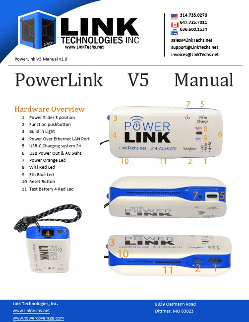
PowerLink V5 Manual v1.0**************************************** **********************PowerLink V5 Manual Hardware Overview1Power Slider 3 position2Function pushbutton3Build in Light4Power Over Ethernet LAN Port5USB-C Charging system 2A6USB Power Out & AC 5Ghz7Power Orange Led8WiFi Red Led9Eth Blue Led10Reset Button11Test Battery 4 Red Led PowerLink V5 Manual v1.0**************************************** **********************Quick Start∙Move the Slider Switch to WiFi or W+P (WiFi + PoE)∙Use a short CAT5 cable to go between the LAN port on the PowerLink V5 and the CPE.∙Connect to SSID∙IP address should come from CPE (if you are configured for DHCP on your wireless device), or you will need to statically configure it.∙Connect to your CPE using web/winbox or installation application.∙Blue Eth Led It is fixed if Ethernet Cable is 100 Ful Duplex, flashing if Half Duplex (Defective)Normally there is no need to login to the PowerLink, unless you wish to do some kind of special configuration, things like change VLANs, SSIDs, security etc. Most of the time the unit will be completely pass-though, and transparent bridging. Most manufacture applications prefer this.WiFi Speed (theoretical):2.4 GHz Width 40Mhz = 86 Mbps2.4 GHz Width 20Mhz = 43 MbpsOptional USB AC StickAC 5Ghz Width 80Mhz = 292(100)MbpsAC 5Ghz Width 40Mhz = 150(100)MbpsAC 5Ghz Width 20Mhz = 72 Mbps PowerLink V5 Manual v1.0**************************************** **********************ContentsHardware Overview (1)Quick Start (1)Features: (4)WiFi Speed (4)Optional USB AC Stick (2)Functions (5)Top Button (5)Reset Button (5)Yellow Battery LED Indicator (5)Display (5)Default Configuration (6)To Automate the Preperation of CPEs (6)Iperf3 (9)Samba3 and USB flash key (20)Repository: (19)Upgrading Firmware (19)NOTICE: Optional 5GHZ AC USB Stick (22)Cat5 Pinout (20)Cambium Cable (20)V cable, for LAN speed test (20) PowerLink V5 Manual v1.0314.735.0270647.725.7011636.660.1534**************************************** **********************Features:∙Passive Power Over Ethernet Device, Ubiquiti, Mikrotik, Cambium, etc.∙WiFi 2.4 GHz - Optional 5GHz AC Module∙7000mA/h for charging external devices.∙Short-circuit, Overload, Temperature protection.∙Ethernet Cable Test∙Automated preparation of CPE antenna. Via Linux script∙OpenWrt / Lede, HTML menu, working opkg repository∙VLAN support∙Iperf3 -s always active∙Samba 3, for files and memory sharing, USB flash memory.∙Works Perfectly with Several Manufacture Apps -- EasyUBNT, Tik-App, Ubntu, Cambium ∙IEEE 802.3 (Pin 4 e 5 +24V, Pin 7 e 8 GND)∙For old Cambium CPE you have to create a LAN cable with reversed power pin.∙One-year warranty.∙USB Out (Charge / Optional AC 5Ghz)∙Wi-Fi∙PoE On∙Accessory:o Hard Caseo USB Cableo LAN Cableo5Ghz AC module (Optional)∙140 grams∙96 x 44 x 97 mm∙MT7620 chipset 2.4GHz∙Two PCB antennas. PowerLink V5 Manual v1.0**************************************** **********************FunctionsPower Slider 3 position -> 1∙Off (PowerBank is working)∙WiFi∙WiFi + PoEYou can tourn off wifi with double click on pushbuttonYou pay much attention, no LED is lit in this condition.Don't forget the poe on.Function pushbutton -> 2∙One click – Turn on PowerBank / Test battery∙Fast Double click – Turn off PowerBank and/or WiFi∙Long click button – Turn on/off LED LightReset Button -> 10The reset button is to either preform a firmware update or to factory Reset the unit. This is typically one of the major troubleshooting steps that∙Pressed during startup – firmware update∙Pressed for 30 seconds – factory reset.LedsThe Power Orange Led 7, blynk if the router is powered on.WiFi Red Led 8, blink when client are associatedEth Blue Led 9, It is fixed if Ethernet Cable is 100 Ful Duplex, flashing if Half Duplex (Defective)4 Red Led, Battery Indicator 11This indicator tells you when the unit is charging, and when it is completed charging. It also will tell you battery level. PowerLink V5 Manual v1.0**************************************** **********************Default ConfigurationTo Connect to the device and change options, you can connect via web browser via http://192.168.1.69 or SSH to the same IP address. The defaultIP Address: 192.168.1.69Username: root password: gevaTo Automate the Preperation of CPEsOn the PowerLInk AT, through ssh connection:/root/CpConf.sh daemon for CPE configuration/root/OnCpScript.sh executed on the CPE for its configuration/root/system.cfg copied on the CPE for its configuration/root/icons.sh daemon that controls icon on TFTOn HTML page of router -> System -> Startup -> Local Startupiperf -s&/root/icons.sh &#/root/CpConf.sh &1.Remove comment (#) on the last line, for enable auto CPE conf.2.Customize OnCpScript.sh for your requirement.3.Copy your CPE configuration file, system.cfg4.Examples work on the Ubiquiti AirOs CPE PowerLink V5 Manual v1.0**************************************** **********************Web InterfaceYou can access the web interface by browsing to 192.168.1.69. The username is root and password is geva. PowerLink V5 Manual v1.0************************************************************** StatusThe tight menu gives you the status page. This includes, overview, Firewall,routes, logs, processes and graphing.The Status page gives you Hardware, Firmware versions and uptime.The network section tellsyou what is in-use andconnected to the device. PowerLink V5 Manual v1.0**************************************** **********************Interface / BridgeUnder Network Interfaces, you have the option to configure new interfaces and/or edit the existing. The default should be LAN, this is a br-lan bridge group. PowerLink V5 Manual v1.0314.735.0270647.725.7011636.660.1534**************************************** **********************By clicking edit, you can edit the LAN interface, this will bring up the following menu options:Here, you have options to select what protocol you wish, this could be used on the ethernet or any other interface. The default option is static address, where the br-lan is statically configured.PowerLink V5 Manual v1.0**************************************************************Other options include; PPP, DHCP Client, or PPPoE. I would always recommend that you bring up the default interface stactially as well as upon boot. NOTE, there is options here that can render the device not reachable, and then a factory reset would be the only option.Under Physical Settings, you can tell that this interface is a bridge, enable STP and/or IGMP snooping, as well as select what interfaces you wish to bridge together. The image below is the default configuration.DHCP-ServerUnder Network Interfaces, hit edit your interface and then you can go to DHCP Server. Here your configure options for DHCP Server.PowerLink V5 Manual v1.0**************************************************************WirelessThis section under status, gives you the wireless access point, SSID and encryption as well as the channel of radios0, this is the 2.4 GHz radio built into the PowerLink AT2. The radio1 would be if you have added the 5 GHz module into the unit.Under Network Wireless, you can configure the wireless interfaces:Once here you can click Edit to edit the WLAN you wish.Here you have options to disable the radio interface, as well as set your network mode, channel, and width.You also have the option to select auto channel if you prefer. PowerLink V5 Manual v1.0**************************************** **********************In advanced settings at the top, you can select your country you are operating in, therefor it will keep the power levels to the max your country supports. NOTE, if you have legacy 802.11b devices, you will need to check the box to allow 802.11b devices, else you can uncheck this. Please test to verify you are not using a legacy device. PowerLink V5 Manual v1.0314.735.0270647.725.7011636.660.1534**************************************************************Under General Setup, you have options for what mode you wish to operate in,Access Point being the most common. Other options include client, ad-hoc,Monitor, and various WDS modes.Changing SSIDYou will change your SSID by going to Network → Wireless → select edit on theradio you wish to modify, then it will be under General Setup. Here you have ESSID,this is your SSID that will appear, if you wish to hide it or change the network thatthis interface operates off of you can do it here.Securing WirelessUnder Network → Wireless → Wireless Security, youhave options to select what security mode you wishto operate in. WPA2-PSK is the recommended. Youwill enter your network key under KEY Isolating ClientsIf you wish, you can click advanced settings under your wireless interface and select the check box to isolate clients. PowerLink V5 Manual v1.0**************************************** **********************VLANsUnder the Network Switch, you have the ability to add VLANs to your configuration. What VLAN ID and whattag or untagged port it should come from. PowerLink V5 Manual v1.0**************************************** **********************FirewallPowerLink V5 Manual v1.0**************************************************************Change PasswordTo Change the PowerLink ATs default password, go to System Administration. Here you can change thedefault password. PowerLink V5 Manual v1.0**************************************** **********************DHCP and DNSIperf3Iperf3 is always running. You can run the following command:iperf3 –c 192.168.1.69On any Linux device, CPE, PC, etc.This Ethernet Test:root@PowerLinkAT:/# iperf3 -s-----------------------------------------------------------Server listening on 5201-----------------------------------------------------------Accepted connection from 192.168.1.30, port 50542[ 5] local 192.168.1.69 port 5201 connected to 192.168.1.30 port 50544[ ID] Interval Transfer Bitrate[ 5] 0.00-1.02 sec 11.4 MBytes 93.5 Mbits/sec[ 5] 1.02-2.01 sec 11.1 MBytes 94.2 Mbits/sec[ 5] 2.01-3.01 sec 11.2 MBytes 94.1 Mbits/sec- - - - - - - - - - - - - - - - - - - - - - - - -[ ID] Interval Transfer Bitrate[ 5] 0.00-9.02 sec 106 MBytes 99.1 Mbits/sec receivergeva@PC: iperf3 -c 192.168.1.69Connecting to host 192.168.1.69, port 5201[ 5] local 172.20.207.228 port 37390 connected to 192.168.1.69 port 5201[ ID] Interval Transfer Bitrate Retr Cwnd[ 5] 0.00-1.00 sec 12.1 MBytes 101 Mbits/sec 0 225 KBytes[ 5] 1.00-2.00 sec 11.4 MBytes 95.6 Mbits/sec 0 236 KBytes[ 5] 2.00-3.00 sec 11.5 MBytes 96.1 Mbits/sec 0 236 KBytes[ 5] 3.00-4.00 sec 10.9 MBytes 91.7 Mbits/sec 0 236 KBytes- - - - - - - - - - - - - - - - - - - - - - - - -[ ID] Interval Transfer Bitrate Retr[ 5] 0.00-9.48 sec 107 MBytes 95.1 Mbits/sec 0 sender [ 5] 0.00-9.48 sec 0.00 Bytes 0.00 bits/sec receiverSamba3 and USB flash keyUSB flash memory FAT32mounted in /mnt/usbkeyAndroid and Linux shared as:192.168.1.69/usbkeySamba3 does not work with windows 10, but you can enable it. (Search in google)PowerLink V5 Manual v1.0**************************************************************Repository:If you set working gateway, repository work, and you can add the modules you need, for example to enable SAMA, GSM dongle, or other drives, the flash free is about 1Mb.Upgrading Firmware3 available solutions1. USB Under 4gig capacity, formatted FAT32, firmware “BatteryPoE_at2.bin”a. Plug in USB, , PowerOff, press Reset.b. Power-On PowerLink AT2c. During Startup the Firmware will be updated.2. Use the Reset Buttona. Press Reset Buttonb. Power-On PowerLink AT2c. When the Power LED blinks, you should be able to acess the Firmware Page of uBoot via web at address http://192.168.1.69/index.htmld. Release reset once you access this page3. On HTML page of the routera. system, backup, update.PowerLink V5 Manual v1.0**************************************************************Appendix:Cat5 PinoutCambium CableThis cable Is for those cambium CPEs that require reversed power pins. It is available on Below is a chart of the Cambium CPE Reversed Power Pin OutV cable, for LAN speed testThis cable allows you to Power your CPE and plug a LAN cable into your device for Ethernet Speed testing, eliminating the need for the Wireless Access Point. This cable is available at AC 5 Ghz adapter。
ct5使用手册摘要:1.CT5 使用手册概述2.安装与设置3.基本功能与操作4.高级功能与应用5.维护与故障排除6.总结正文:一、CT5 使用手册概述CT5 是一款先进的设备,适用于各种场合。
本手册旨在帮助用户更好地理解、安装、操作和维护CT5 设备。
本手册包含设备概述、安装与设置、基本功能与操作、高级功能与应用、维护与故障排除等内容,以确保用户能够充分利用CT5 的功能,实现高效工作。
二、安装与设置1.设备安装在开始使用CT5 之前,请确保设备已正确安装。
请参考安装指南,确保设备安装在稳固的支架上,并正确连接所有电缆。
2.设备设置启动CT5 设备后,按照屏幕提示进行基本设置。
设置包括但不限于:语言、单位、通讯方式等。
确保所有设置符合实际需求。
三、基本功能与操作1.设备启动与关闭了解如何启动和关闭CT5 设备。
在操作面板上找到相应的按钮,按下按钮即可启动或关闭设备。
2.操作面板说明操作面板上包含多个按键和指示灯。
了解各个按键的功能和指示灯的含义,有助于更好地操作设备。
3.基本操作流程本部分将介绍如何进行基本的操作,包括:选择工作模式、输入参数、开始工作等。
四、高级功能与应用1.高级功能介绍CT5 设备具备多种高级功能,如:自动调节、远程控制、数据记录等。
了解这些功能,有助于提高工作效率。
2.高级功能操作方法本部分将详细介绍如何使用高级功能,包括:如何设置自动调节参数、如何进行远程控制、如何记录和导出数据等。
五、维护与故障排除1.设备维护为了确保CT5 设备正常运行,需要定期进行维护。
本部分将介绍维护的具体步骤和注意事项。
2.故障排除如遇到设备故障,请参照本部分提供的故障排除方法。
本部分将介绍常见的故障现象及解决方法。
六、总结本手册介绍了CT5 设备的安装、设置、操作、维护和故障排除等内容。
通过学习本手册,用户应能够熟练掌握CT5 设备的使用方法,提高工作效率。

恒阳v5智能锁五合一说明书恒阳v5智能锁是一款集五种功能于一体的智能锁,具有高度安全性和便捷性。
本文将详细介绍恒阳v5智能锁的五合一功能,并对其使用方法做出说明。
一、指纹解锁恒阳v5智能锁采用先进的生物识别技术,可以通过识别用户的指纹进行解锁。
用户只需将手指放在指纹识别区域,即可快速解锁。
指纹解锁不仅速度快,而且具有高度安全性,有效防止他人非法开锁。
二、密码解锁除了指纹解锁外,恒阳v5智能锁还支持密码解锁功能。
用户可以通过设置自己的密码来解锁智能锁。
密码解锁的好处是方便记忆,而且可以随时更改密码,增加了解锁的灵活性。
三、IC卡解锁恒阳v5智能锁还具备IC卡解锁功能。
用户可以通过刷卡的方式来解锁智能锁。
每个用户可以拥有一张或多张IC卡,方便家庭成员或办公室员工使用。
四、手机APP解锁恒阳v5智能锁与手机APP相连接,用户可以通过手机APP进行解锁。
只需在手机上下载并安装相应的APP,将手机与智能锁绑定后,用户可以通过APP实现解锁、查看开锁记录等功能。
手机APP解锁功能方便快捷,适用于喜欢使用手机的用户。
五、钥匙解锁除了以上四种解锁方式外,恒阳v5智能锁还备有物理钥匙解锁功能。
用户可以使用备用的钥匙来解锁智能锁,确保在特殊情况下仍能正常开锁。
恒阳v5智能锁具备指纹解锁、密码解锁、IC卡解锁、手机APP解锁和钥匙解锁五种功能。
无论是家庭、办公室还是其他场所,都能满足用户的多样化需求。
此外,恒阳v5智能锁还配备有防撬报警、密码保护、远程控制等安全功能,极大提升了门锁的安全性。
用户可以根据实际需求选择适合自己的解锁方式,提供了更加便捷、安全的门锁使用体验。

鹿客v5max手册【最新版】目录1.鹿客 v5max 手册概述2.鹿客 v5max 的功能特点3.鹿客 v5max 的使用方法4.鹿客 v5max 的维护保养5.鹿客 v5max 的用户评价正文1.鹿客 v5max 手册概述鹿客 v5max 手册是一款智能锁具产品的用户指南,旨在帮助用户更好地了解和使用鹿客 v5max 智能锁。
该手册详细地介绍了鹿客 v5max 的功能特点、使用方法、维护保养等方面的内容,让用户能够更便捷、安全地享受智能锁具带来的便利。
2.鹿客 v5max 的功能特点鹿客 v5max 作为一款先进的智能锁具,具有以下功能特点:(1)高安全性:采用半导体指纹识别技术,识别速度快,准确率高,有效防止伪指纹攻击。
(2)便捷性:支持手机 APP 远程控制,用户可以随时随地控制家门锁状态。
(3)耐用性:采用不锈钢材质,经久耐用,抗磨损。
(4)应急开锁:在电池电量耗尽的情况下,用户可以使用应急钥匙进行开锁。
3.鹿客 v5max 的使用方法鹿客 v5max 的使用方法分为以下几个步骤:(1)安装:根据产品附带的安装指南,用户可以自行安装锁具,也可以选择预约专业人员上门安装。
(2)注册:用户需下载鹿客 APP,注册并绑定手机号,完成账户创建。
(3)设置:在 APP 中设置门锁权限,添加家庭成员或临时访客,并根据需要设置开锁方式。
(4)开锁:用户可以使用指纹、密码、手机 APP 等方式开锁。
4.鹿客 v5max 的维护保养为了确保鹿客 v5max 的正常使用和延长使用寿命,用户需要定期进行维护保养,具体包括:(1)清洁:定期清洁锁具表面,避免污渍和灰尘影响锁具的美观和性能。
(2)检查:定期检查锁具的电池电量,确保其正常工作。
如发现电池电量不足,请及时更换电池。
(3)升级:及时更新鹿客 APP 和锁具的固件,以获得最新的功能和优化。
5.鹿客 v5max 的用户评价根据市场调查和用户反馈,鹿客 v5max 智能锁具在安全性、便捷性、耐用性等方面得到了用户的一致好评。
catiaV5中英文菜单对照及基本使用手册F3------隐藏目录树F1------实时帮助ctrl+z---------撤消ctrl+y--------redoctrl+n--------新建ctrl+o--------打开ctrl+鼠标中键视图放大缩小alt+鼠标中键视图平移alt+鼠标左键+鼠标中键视图旋转Alt+Enter=性质hift加中键出现红色方块后拖拉即可快速缩放大小这非常好用先按CTRL再加中键是放大缩小先按中键再加CTRL是是对象旋转而对象旋转时外面会出现红色的圆形区域在圆形区域内是某YZ轴的任意旋转而在圆形区域外是针对Z轴的特定旋转用鼠标指向某个封闭空心实体外表面,然后按键盘方向键,就可以选到内表面!ctrl+F11,出现物体选择器。
Ctrl+Pageup-------zoominCtrl+Pagedown------zoomoutAlt+hift+上下左右箭头----rotateCtrl+上下左右箭头----panCtrl+hift+左右箭头——————rotatehift+F3--workonpecificationtreehift+F2--pecificationtreeoverview(在工具拦)MB3+Cutomize.......可自定义在自由造型与A级曲面中:F5--调出“操作平面对话框”(对“由N点成面”等命令尤为重要)控制金钱,可以得到财富;控制餐饮,可以得到健康;控制情绪,可以得到快乐;控制感情,可以得到幸福。
学会控制,可以得到更多。
零件设计PDG:PartDeign装配设计ASD:AemblyDeign交互式工程绘图IDR:InteractiveDrafting创成式工程绘图GDR:GenerativeDrafting结构设计STD:StructureDeign线架和曲面设计WSF:WireframeandSurface钣金设计SMD:SheetMetalDeign航空钣金设计ASL:AeropaceSheetmetalDeign钣金加工设计SHP:SheetMetalProduction三维功能公差与标注设计FTA:3DFunctionalTolerancing&Annotation模具设计MTD:MoldToolingDeign阴阳模设计CCV:Core&CavityDeign焊接设计WDG:WeldDeign自由风格曲面造型FSS:FreeStyleShaper自由风格曲面优化FSO:FreeStyleOptimizer基于截面线的自由风格曲面造型FSP:FreeStyleProfiler基于草图的自由风格曲面造型FSK:FreeStyleSketchTracer创成式外形设计GSD:GenerativeShapeDeign创成式曲面优化GSO:GenerativeShapeOptimizer汽车白车身接合ABF:AutomotiveBodyInWhiteFatening数字化外形编辑DSE:DigitizedShapeEditor汽车A级曲面造型ACA:AutomotiveClaA快速曲面重建QSR:QuickSurfaceRecontruction创成式零件结构分析GPS:GenerativePartStructuralAnalyi创成式装配件结构分析GAS:GenerativeAemblyStructuralAnalyi变形装配件公差分析TAA:ToleranceAnalyiofDeformableAemblyElfini结构分析EST:ElfiniSolverVerification电路板设计CBD:CircuitBoardDeign电气系统功能定义EFD:ElectricalSytemFunctionalDefinition电气元件库管理员ELB:ElectricalLibrary电气线束安装EHI:ElectricalHarneIntallation电气线束布线设计EWR:ElectricalWireRouting电气线束展平设计EHF:ElectricalHarneFlattening管路和设备原理图设计PID:Piping&IntrumentationDiagramHVAC图表设计HVD:HVACDiagram电气连接原理图设计ELD:ElectricalConnectivityDiagram系统原理图设计SDI:SytemDiagram管线原理图设计TUD:TubingDiagram波导设备原理图设计WVD:WaveguideDiagram系统布线设计SRT:SytemRouting系统空间预留设计SSR:SytemSpaceReervation电气缆线布线设计ECR:ElectricalCablewayRouting设备布置设计EQT:EquipmentArrangement线槽与导管设计RCD:Raceway&ConduitDeign波导设备设计WAV:WaveguideDeign管路设计PIP:PipingDeign管线设计TUB:TubingDeignHVAC设计HVA:HVACDeign支架设计HGR:HangerDeign结构初步布置设计SPL:StructurePreliminaryLayout结构功能设计SFD:StructureFunctionalDeign设备支撑结构设计ESS:EquipmentSupportStructure厂房设计PLOPlantLayout数控加工审查NCG:NCManufacturingReview数控加工验证NVG:NCManufacturingVerification2轴半加工准备助手PMA:PrimaticMachiningPreparationAitant2轴半加工PMG:PrimaticMachining3轴曲面加工SMG:3A某iSurfaceMachining多轴曲面加工MMG:Multi-A某iSurfaceMachining车削加工LMG:LatheMachining高级加工AMG:AdvancedPartMachiningSTL快速成型STL:STLRapidPrototyping知识工程顾问KWA:KnowledgeAdvior知识工程专家KWE:KnowledgeE某pert产品工程优化PEO:ProductEngineeringOptimizer产品知识模板PKT:ProductKnowledgeTemplate业务流程知识模板BKT:BuineProceKnowledgeTemplate产品功能定义PFD:ProductFunctionDefinition产品功能优化PFO:ProductFunctionOptimizerDMU漫游器DMN:DMNDMUNavigatorDMU运动机构模拟KIN:DMUKinematicSimulatorDMU空间分析SPA:DMUSpaceAnalyiDMU装配模拟FIT:DMUFittingSimulatorDMU优化器DMO:DMUOptimizerDMU工程分析审查ANR:DMUEngineeringAnalyiReviewDMU空间工程助手SPE:DMUSpaceEngineeringAitant人体模型构造器HBR:HumanBuilder人体模型测量编辑HME:HumanMeaurementEditor人体姿态分析HPA:HumanPotureAnalyi人体行为分析HAA:HumanActivityAnalyi。
大眼橙v5定制版使用说明大眼橙v5定制版是一款功能强大且易于使用的软件,旨在帮助用户更高效地完成各类任务。
本使用说明将详细介绍如何正确使用大眼橙v5定制版,以便用户能够轻松上手并充分利用其提供的各种功能。
1. 安装和启动- 下载大眼橙v5定制版软件并按照提示进行安装。
- 启动软件后,您将看到一个简洁而直观的用户界面。
2. 创建任务- 点击“新建任务”按钮,输入任务的名称和描述。
- 根据需要选择任务的类型,例如项目管理、日程安排等。
- 设置任务的优先级、截止日期和提醒方式等详细信息。
3. 添加任务步骤- 在任务详情页中,点击“添加步骤”按钮。
- 输入步骤的名称和描述。
- 设置步骤的完成要求和截止日期等信息。
4. 分配任务- 点击任务详情页中的“分配给”选项。
- 输入或选择要分配任务的成员。
- 协作者将收到任务分配的通知并可以开始执行任务。
5. 完成任务- 任务执行者可以在任务详情页中按照步骤完成任务。
- 可以将相关文件、图片等附件添加到任务中。
- 点击“完成”按钮以标记任务为完成状态。
6. 任务跟踪与提醒- 在任务列表中,您可以轻松地查看所有任务的状态和进度。
- 大眼橙v5定制版还支持提醒功能,以确保您不会错过任何重要任务的截止日期或进展情况。
7. 任务统计和报告- 大眼橙v5定制版提供了丰富的统计和报告功能。
- 您可以查看个人或团队的任务完成情况统计报告。
- 这些报告可以帮助您评估工作进展,优化任务分配和提高团队的效率。
总结:大眼橙v5定制版是一款强大而易于使用的任务管理软件,它帮助用户轻松创建、分配和跟踪任务,实现高效的工作和团队协作。
通过正确使用大眼橙v5定制版的各项功能,您可以更好地管理任务并提高工作效率。
帕娜碧亚v5使用说明书
1. 录影模式
按下电源开关键ON/OFF或连接充电器后,记录仪会自动进入录影模式并开始录影,此时蓝色指示灯闪烁。
录影时按REC/SNAP键停止录影,此时指示灯常亮。
按MENU键进入主菜单。
2. 拍照模式
开机后按MODE键选择进入拍照模式,按REC/SNAP进行拍照。
按MENU键进入子菜单。
3. 预览模式
开机后按MODE键选择进入预览模式,按UP、DOWN选择视频文件或照片文件,按REC/SNAP播放或暂停,按MODE退出预览。
4. 日期时间设置
在录影界面(停止录影)按MENU(菜单)键,再按MODE(模式)键,在系统菜单界面选择项,按MENU(菜单)或REC(录影)键进入下一级菜单,按MENU(菜单)或REC(录影)键选择设置项。
在日期时间设置界面按REC(录影)键或MENU(菜单)键进入下一个设置,使用上翻/下翻对年/月/日、时间进行调整,设定好后按MENU(菜单)或REC(录影)键确定退出。
乐行天下v5d说明书
乐行天下V5D是一款功能强大的出行工具,让您的旅行更加方便、快捷。
下面将为您介绍其使用方法及注意事项。
首先,乐行天下V5D的操作非常简单,只需按下电源按钮,即可
启动设备。
它拥有高清晰度显示屏,界面简洁明了,方便您快速找到
所需的功能。
同时,设备还配备了触摸屏,您可以通过手指轻轻滑动
操作,实现各种功能的切换。
其次,乐行天下V5D具备多种导航方式,包括车载导航、步行导航,甚至骑行导航等。
您只需输入目的地,系统将为您规划最佳路线,并提供详细的实时导航指引。
无论是在城市还是乡村,乐行天下V5D
都能准确地指引您前行,让您不再为迷路而烦恼。
此外,乐行天下V5D还支持多种语音交互功能,您只需通过语音
输入,即可轻松实现导航、查询天气、打电话等操作。
这对于驾车者
来说尤为方便,可以保持双手的安全驾驶状态。
乐行天下V5D还具备实时路况播报功能,可以及时提供道路拥堵
情况、事故警报等信息,让您合理规划行车路线,避免堵车。
同时,
设备还提供天气预报、电子眼提醒等实用功能,让您的出行更加安全
且充满乐趣。
最后,使用乐行天下V5D需要注意的是保持设备的正常使用环境,避免长时间暴露在高温、潮湿等情况下。
同时,请及时更新系统和地
图版本,以获得更好的使用体验。
总之,乐行天下V5D是一款功能强大、操作简单的出行工具。
它
不仅可以为您提供准确的导航指引,还具备实时路况播报、语音交互
等实用功能。
相信使用乐行天下V5D,您的旅行将更加省心、安全且方便。
文档密级WA1208EV5版本软件升级操作指导第1章前言目前的WA1208E产品运行的软件平台主要是ComwareV3的,WA1208E不支持IPV6。
现有的WLAN软件平台为ComwareV5,支持IPV6,同时WLAN软件平台丰富的特性不能应用在WA1208E产品。
为进一步提高产品竞争力,减少维护成本,需要移植WA1208E产品至ComwareV5平台。
WA1208E 属于FAT AP产品架构,为了更灵活的适应市场需求,需要使WA1208E 支持FAT AP和FIT AP两种架构模式的兼容。
ComwareV3和ComwareV5基本上是不同的软件体系,而且不能够相互兼容,本操作说明就是给操作者提供帮助,顺利完成从V3到V5版本的切换,另外,本文档可以重点关注V5版本Bootrom加载和运行V3版本APP和ART软件的过程。
第2章从V3版本切换到V5版本过程由于V3和V5是两套完全不同的软件体系,V3版本的Bootrom是一段式结构,而V5版本的Bootrom分为基本段和扩展段,所以升级过程需要通过一个过渡版本的软件来完成,目前是通过一个基于V3版本的BootRom来操作的,目前暂且定为是BootromV3_tmp。
升级过程主要是将V3的Bootrom切换成V5的Bootrom的过程。
大体上两步可以完成:当前V3设备—>BootromV3_tmp—>BootromV5,然后就可以在这个软件上面运行V5的APP软件,同时可以运行V3的APP软件和两种平台的ART软件,两种平台下的文件系统是完全兼容的,一般情况下不需要单独的格式化处理。
具体的操作步骤如下描述:文档密级2.1 V3 Bootrom环境下升级Bootrom到BootromV3_tmp这个操作可以通过FTP、TFTP以及XMODEM来完成,由于速度较快,我们一般推荐用TFTP或FTP。
1. 进入V3版本Bootrom菜单,CTR+R进入Bootrom升级界面图2-1Comware V3环境下Bootrom升级界面2.设置在Bootrom中升级的参数,包括文件名称\serverIP\clientIP等图2-2按提示信息完成升级步骤界面3. 按提示完成升级的操作,升级成功,系统自动重起如果网络配置正确,则可以顺利升级,否则需要检查网络配置和Bootrom参数设置。
ALTRONIC AGV5OPERATING MANUAL GAS FUEL VALVE FORM AGV5 OM 8-031.0 OVERVIEW1.1This manual provides instruction and maintenance information for the Advanced Gas Valve,models AGV5-xx with the Altronic circuit board assembly 872005-1. It is recommended that the user read this manual in its entirety before commencing operations.It is not our intention to instruct others on how to design control systems, nor can we assume responsibility for their safe operation. This advice is intended to help the end user install the AGV5 Gas Valve in such a manner to reduce the risk of accident to personnel or to equipment.1.2The Altronic AGV5 Gas Valves are normally used with natural gas. Natural gas and air, whencombined together, become very combustible and when contained within an enclosure, such as a gas engine or its exhaust system, combusts in a violent manner when ignited. It is necessary to always use extreme caution when working with any fuel system. The control systems used with gas engines or other similar machines should always be designed to be “fail-safe”. Towards this goal, the AGV5 Gas Valve plays an important part in the safety of the whole system.-1-2.0 INSTALLATION2.1The Gas Valve should be inspected immediately after unpacking. Check for any damage thatmay have occurred during shipping. If there are any questions regarding the physical integrity of the valve, contact the distributor or Altronic, Inc.NOTE: If possible, keep the original shipping container. If future transportation or storage of the valve is necessary, this container will provide the optimum protection.2.2The AGV5 Gas Valve is designed to be installed on natural gas fired, reciprocating engines.It is a flow-controlling device that responds to a 4 to 20 mA signal from a controlling device (for example, PLC) and throttles the fuel available to the engine. When considering where to place the AGV5 Gas Valve, choose a location away from any extreme sources of heat.Operating ambient temperature is –40°F. to +185°F / –40°C. to +85°C. Do not expose the valve to temperatures higher than indicated here.2.3The AGV5 can be mounted either horizontally or vertically using its 2.0 inch, 4-bolt, 150 classANSI flanges. It is recommended that the AGV5 be placed within a straight run of piping to provide adequate fuel flow control. For dimensions, refer to drawing 809 023.-2-3.0 ELECTRICAL CONNECTIONS3.1Refer to drawing 809 024 for electrical hookup details. The installation must conform to theapplicable electrical code concerning hazardous environment installations.WARNING: DO NOT DISCONNECT EQUIPMENT UNLESS POWER HAS BEEN SWITCHED OFF OR THE AREA IS KNOWN TO BE NON-HAZARDOUS.WARNING: SUBSTITUTION OF COMPONENTS MAY IMPAIR SUITABILITY FOR CLASS 1, DIVISION 1 OR 2.CAUTION: KEEP COVERS TIGHT WHILE CIRCUITS ARE ALIVE.The equipment may be installed in Class I, Division 1 or 2, Group D hazardous locations.Because of these requirements, the wiring methods to be used are threaded, rigid metal conduit or flexible conduit and termination fittings, in all cases approved for the location. Fora Division 1 installation, the entire assembly is to be explosion-proof.4.0 POWER SUPPLY4.1The the AGV5 requires +20 to 36 Vdc supply (+24 Vdc typical) with peak currents ofapproximately 5 amps. The minimum wire size to the valve must be 16AWG. If long distances between control device and the AGV5 are expected, the wire size may have to be increased to compensate for the associated voltage drop.5.0 CONTROL SIGNALS5.1The AGV5 valve position input signal is a 4 to 20 mA signal.NOTE: Current to the AGV5 valve position input must never exceed the maximum of the calibrated range.The valve position input signal, position feedback signal and pressure feedback signal from the AGV5 Gas Valve are non-isolated signals. If both of these signals are being connected to a source with the same ground (i.e. the same PLC), no problem is usually encountered using direct connections.-3-5.2If any other devices are connected in the demand or feedback circuits, or if demand andfeedback are connected to different devices, care must be exercised not to create potential ground loops. An example is using an external electronic governor on generator sets. Even if the external devices are powered from the same source, the internal circuitry of the external devices may cause a ground potential difference. Different ground voltage potentials in the demand or feedback circuits will cause ground loops to the AGV5.To avoid ground loops when the demand and feedback signals are wired to different devices, or when external devices are to be added to either circuit, it is recommended that signal isolators be installed in the feedback wiring. Most signal isolators have significant time delays between their input and output. These delays can cause problems if the isolators are wired into the valve position signal.6.0 CALIBRATION6.1The standard factory calibration for AGV5 valve is:At 100 psig, Cv = 0 at 4 mA, Cv = 10 at 20 MaSee the flow capacity curve drawing 809 029.7.0 PLC CONFIGURATION7.1The AGV5 is designed to be controlled by a PLC (Programmable Logic Controller). Theappropriate analog inputs, outputs and discrete relay output must be configured and wired before the AGV5 will operate. The AGV5 valve may be controlled by analog inputs that control position or pressure. A low-select feature selecting the lower of either of these is also available. See the overall control diagram 809 025 and the three logic diagrams (809 026, 809 027 and 809 028) for each control mode in these instructions.NOTE: AGV5 valves with serial number 400 and higher are configured as follows:1. Control is by pressure if input connection is only to pressure.2. Control is by position if input connection is only to position.3. Control is by low-select if input connection is to both pressure and position.It is recommended that an interposing relay be installed with the AGV5 power wiring to provide a means of emergency shutdown. The relay would be wired to interrupt the power to the AGV5 in the event the system (PLC) detects a faulty condition. An output of the PLC should control the actuating coil of the relay. When the engine is shut down, the block and bleed valve should close, and the input to the AGV5 should be 4 mA to minimize heating of the valve with no gas flow.-4-DRAWINGS:809 023GAS METERING VALVE, AGV5809 024WIRING DIAGRAM, AGV5809 025CONTROL DRAWING, AGV5 FROM A PLC 809 026PRESSURE CONTROL DIAGRAM, AGV5 809 027POSITION CONTROL DIAGRAM, AGV5 809 028LOW SELECT DIAGRAM, AGV5809 029MAX FLOW CAPACITY OF AGV5-5-。
使 用 说 明 书V50X 运动相机目录配件清单产品简介快速入门相机模式操作指南 个性化设置 App连接 回放 删除 导出相机维护电池维护配件使用联系我们1 2 4 5 6 7 10 11 12 12 13 13 14 16--------------------------------------------------------------------------------------------------------------------------------------------------------------------------------------------------------------------------------------------------------------------------------------------------------------------------------------------------------------------------------------------------------------------------------------------------------------------------------------------------------------------------------------------------------------------------------------------------------------------------------------------------------------------------------------------------------------------------------------------------------------------------------------------------------------------------------------------------------------------------------------------------------------------------------------------------------------------------------------------------------------------------------------------------------------------------------------------------------------------------------------------------------------------------------------------------------------------------------------------------------------配件清单运动相机 × 1防水壳 × 1遥控器 × 1充电器 × 1转轴 × 7扎带 × 51350mAh 电池 × 2自行车支架 × 1快速操作指南 × 1保修卡 × 1绑带 × 4头盔底座 × 2USB数据线 × 1防尘背盖 × 1注意:当相机套上防水壳后不能录制声音。