ramakrishnan-DataIntensiveWorkflows-v2
- 格式:pdf
- 大小:696.52 KB
- 文档页数:9

人工智能是一门新兴的具有挑战力的学科。
自人工智能诞生以来,发展迅速,产生了许多分支。
诸如强化学习、模拟环境、智能硬件、机器学习等。
但是,在当前人工智能技术迅猛发展,为人们的生活带来许多便利。
下面是搜索整理的人工智能英文参考文献的分享,供大家借鉴参考。
人工智能英文参考文献一:[1]Lars Egevad,Peter Str?m,Kimmo Kartasalo,Henrik Olsson,Hemamali Samaratunga,Brett Delahunt,Martin Eklund. The utility of artificial intelligence in the assessment of prostate pathology[J]. Histopathology,2020,76(6).[2]Rudy van Belkom. The Impact of Artificial Intelligence on the Activities ofa Futurist[J]. World Futures Review,2020,12(2).[3]Reza Hafezi. How Artificial Intelligence Can Improve Understanding in Challenging Chaotic Environments[J]. World Futures Review,2020,12(2).[4]Alejandro Díaz-Domínguez. How Futures Studies and Foresight Could Address Ethical Dilemmas of Machine Learning and Artificial Intelligence[J]. World Futures Review,2020,12(2).[5]Russell T. Warne,Jared Z. Burton. Beliefs About Human Intelligence in a Sample of Teachers and Nonteachers[J]. Journal for the Education of the Gifted,2020,43(2).[6]Russell Belk,Mariam Humayun,Ahir Gopaldas. Artificial Life[J]. Journal of Macromarketing,2020,40(2).[7]Walter Kehl,Mike Jackson,Alessandro Fergnani. Natural Language Processing and Futures Studies[J]. World Futures Review,2020,12(2).[8]Anne Boysen. Mine the Gap: Augmenting Foresight Methodologies with Data Analytics[J]. World Futures Review,2020,12(2).[9]Marco Bevolo,Filiberto Amati. The Potential Role of AI in Anticipating Futures from a Design Process Perspective: From the Reflexive Description of “Design” to a Discussion of Influences by the Inclusion of AI in the Futures Research Process[J]. World Futures Review,2020,12(2).[10]Lan Xu,Paul Tu,Qian Tang,Dan Seli?teanu. Contract Design for Cloud Logistics (CL) Based on Blockchain Technology (BT)[J]. Complexity,2020,2020.[11]L. Grant,X. Xue,Z. Vajihi,A. Azuelos,S. Rosenthal,D. Hopkins,R. Aroutiunian,B. Unger,A. Guttman,M. Afilalo. LO32: Artificial intelligence to predict disposition to improve flow in the emergency department[J]. CJEM,2020,22(S1).[12]A. Kirubarajan,A. Taher,S. Khan,S. Masood. P071: Artificial intelligence in emergency medicine: A scoping review[J]. CJEM,2020,22(S1).[13]L. Grant,P. Joo,B. Eng,A. Carrington,M. Nemnom,V. Thiruganasambandamoorthy. LO22: Risk-stratification of emergency department syncope by artificial intelligence using machine learning: human, statistics or machine[J]. CJEM,2020,22(S1).[14]Riva Giuseppe,Riva Eleonora. OS for Ind Robots: Manufacturing Robots Get Smarter Thanks to Artificial Intelligence.[J]. Cyberpsychology, behavior and social networking,2020,23(5).[15]Markus M. Obmann,Aurelio Cosentino,Joshy Cyriac,Verena Hofmann,Bram Stieltjes,Daniel T. Boll,Benjamin M. Yeh,Matthias R. Benz. Quantitative enhancement thresholds and machine learning algorithms for the evaluation of renal lesions using single-phase split-filter dual-energy CT[J]. Abdominal Radiology,2020,45(1).[16]Haytham H. Elmousalami,Mahmoud Elaskary. Drilling stuck pipe classification and mitigation in the Gulf of Suez oil fields using artificial intelligence[J]. Journal of Petroleum Exploration and Production Technology,2020,10(10).[17]Rüdiger Schulz-Wendtland,Karin Bock. Bildgebung in der Mammadiagnostik –Ein Ausblick <trans-title xml:lang="en">Imaging in breast diagnostics—an outlook [J]. Der Gyn?kologe,2020,53(6).</trans-title>[18]Nowakowski Piotr,Szwarc Krzysztof,Boryczka Urszula. Combining an artificial intelligence algorithm and a novel vehicle for sustainable e-waste collection[J]. Science of the Total Environment,2020,730.[19]Wang Huaizhi,Liu Yangyang,Zhou Bin,Li Canbing,Cao Guangzhong,Voropai Nikolai,Barakhtenko Evgeny. Taxonomy research of artificial intelligence for deterministic solar power forecasting[J]. Energy Conversion and Management,2020,214.[20]Kagemoto Hiroshi. Forecasting a water-surface wave train with artificial intelligence- A case study[J]. Ocean Engineering,2020,207.[21]Tomonori Aoki,Atsuo Yamada,Kazuharu Aoyama,Hiroaki Saito,Gota Fujisawa,Nariaki Odawara,Ryo Kondo,Akiyoshi Tsuboi,Rei Ishibashi,Ayako Nakada,Ryota Niikura,Mitsuhiro Fujishiro,Shiro Oka,Soichiro Ishihara,Tomoki Matsuda,Masato Nakahori,Shinji Tanaka,Kazuhiko Koike,Tomohiro Tada. Clinical usefulness of a deep learning‐based system as the first screening on small‐bowel capsule endoscopy reading[J]. Digestive Endoscopy,2020,32(4).[22]Masashi Fujii,Hajime Isomoto. Next generation of endoscopy: Harmony with artificial intelligence and robotic‐assisted devices[J]. Digestive Endoscopy,2020,32(4).[23]Roberto Verganti,Luca Vendraminelli,Marco Iansiti. Innovation and Design in the Age of Artificial Intelligence[J]. Journal of Product Innovation Management,2020,37(3).[24]Yuval Elbaz,David Furman,Maytal Caspary Toroker. Modeling Diffusion in Functional Materials: From Density Functional Theory to Artificial Intelligence[J]. Advanced Functional Materials,2020,30(18).[25]Dinesh Visva Gunasekeran,Tien Yin Wong. Artificial Intelligence in Ophthalmology in 2020: A Technology on the Cusp for Translation and Implementation[J]. Asia-Pacific Journal of Ophthalmology,2020,9(2).[26]Fu-Neng Jiang,Li-Jun Dai,Yong-Ding Wu,Sheng-Bang Yang,Yu-Xiang Liang,Xin Zhang,Cui-Yun Zou,Ren-Qiang He,Xiao-Ming Xu,Wei-De Zhong. The study of multiple diagnosis models of human prostate cancer based on Taylor database by artificial neural networks[J]. Journal of the Chinese Medical Association,2020,83(5).[27]Matheus Calil Faleiros,Marcello Henrique Nogueira-Barbosa,Vitor Faeda Dalto,JoséRaniery Ferreira Júnior,Ariane Priscilla Magalh?es Tenório,Rodrigo Luppino-Assad,Paulo Louzada-Junior,Rangaraj Mandayam Rangayyan,Paulo Mazzoncini de Azevedo-Marques. Machine learning techniques for computer-aided classification of active inflammatory sacroiliitis in magnetic resonance imaging[J]. Advances in Rheumatology,2020,60(1078).[28]Balamurugan Balakreshnan,Grant Richards,Gaurav Nanda,Huachao Mao,Ragu Athinarayanan,Joseph Zaccaria. PPE Compliance Detection using Artificial Intelligence in Learning Factories[J]. Procedia Manufacturing,2020,45.[29]M. Stévenin,V. Avisse,N. Ducarme,A. de Broca. Qui est responsable si un robot autonome vient à entra?ner un dommage ?[J]. Ethique et Santé,2020.[30]Fatemeh Barzegari Banadkooki,Mohammad Ehteram,Fatemeh Panahi,Saad Sh. Sammen,Faridah Binti Othman,Ahmed EL-Shafie. Estimation of Total Dissolved Solids (TDS) using New Hybrid Machine Learning Models[J]. Journal of Hydrology,2020.[31]Adam J. Schwartz,Henry D. Clarke,Mark J. Spangehl,Joshua S. Bingham,DavidA. Etzioni,Matthew R. Neville. Can a Convolutional Neural Network Classify Knee Osteoarthritis on Plain Radiographs as Accurately as Fellowship-Trained Knee Arthroplasty Surgeons?[J]. The Journal of Arthroplasty,2020.[32]Ivana Nizetic Kosovic,Toni Mastelic,Damir Ivankovic. Using Artificial Intelligence on environmental data from Internet of Things for estimating solar radiation: Comprehensive analysis[J]. Journal of Cleaner Production,2020.[33]Lauren Fried,Andrea Tan,Shirin Bajaj,Tracey N. Liebman,David Polsky,Jennifer A. Stein. Technological advances for the detection of melanoma: Part I. Advances in diagnostic techniques[J]. Journal of the American Academy of Dermatology,2020.[34]Mohammed Amoon,Torki Altameem,Ayman Altameem. Internet of things Sensor Assisted Security and Quality Analysis for Health Care Data Sets Using Artificial Intelligent Based Heuristic Health Management System[J]. Measurement,2020.[35]E. Lotan,C. Tschider,D.K. Sodickson,A. Caplan,M. Bruno,B. Zhang,Yvonne W. Lui. Medical Imaging and Privacy in the Era of Artificial Intelligence: Myth, Fallacy, and the Future[J]. Journal of the American College of Radiology,2020.[36]Fabien Lareyre,Cédric Adam,Marion Carrier,Juliette Raffort. Artificial Intelligence in Vascular Surgery: moving from Big Data to Smart Data[J]. Annals of Vascular Surgery,2020.[37]Ilesanmi Daniyan,Khumbulani Mpofu,Moses Oyesola,Boitumelo Ramatsetse,Adefemi Adeodu. Artificial intelligence for predictive maintenance in the railcar learning factories[J]. Procedia Manufacturing,2020,45.[38]Janet L. McCauley,Anthony E. Swartz. Reframing Telehealth[J]. Obstetrics and Gynecology Clinics of North America,2020.[39]Jean-Emmanuel Bibault,Lei Xing. Screening for chronic obstructive pulmonary disease with artificial intelligence[J]. The Lancet Digital Health,2020,2(5).[40]Andrea Laghi. Cautions about radiologic diagnosis of COVID-19 infection driven by artificial intelligence[J]. The Lancet Digital Health,2020,2(5).人工智能英文参考文献二:[41]K. Orhan,I. S. Bayrakdar,M. Ezhov,A. Kravtsov,T. ?zyürek. Evaluation of artificial intelligence for detecting periapical pathosis on cone‐beam computed tomography scans[J]. International Endodontic Journal,2020,53(5).[42]Avila A M,Mezi? I. Data-driven analysis and forecasting of highway traffic dynamics.[J]. Nature communications,2020,11(1).[43]Neri Emanuele,Miele Vittorio,Coppola Francesca,Grassi Roberto. Use of CT andartificial intelligence in suspected or COVID-19 positive patients: statement of the Italian Society of Medical and Interventional Radiology.[J]. La Radiologia medica,2020.[44]Tau Noam,Stundzia Audrius,Yasufuku Kazuhiro,Hussey Douglas,Metser Ur. Convolutional Neural Networks in Predicting Nodal and Distant Metastatic Potential of Newly Diagnosed Non-Small Cell Lung Cancer on FDG PET Images.[J]. AJR. American journal of roentgenology,2020.[45]Coppola Francesca,Faggioni Lorenzo,Regge Daniele,Giovagnoni Andrea,Golfieri Rita,Bibbolino Corrado,Miele Vittorio,Neri Emanuele,Grassi Roberto. Artificial intelligence: radiologists' expectations and opinions gleaned from a nationwide online survey.[J]. La Radiologia medica,2020.[46]?. ? ? ? ? [J]. ,2020,25(4).[47]Savage Rock H,van Assen Marly,Martin Simon S,Sahbaee Pooyan,Griffith Lewis P,Giovagnoli Dante,Sperl Jonathan I,Hopfgartner Christian,K?rgel Rainer,Schoepf U Joseph. Utilizing Artificial Intelligence to Determine Bone Mineral Density Via Chest Computed Tomography.[J]. Journal of thoracic imaging,2020,35 Suppl 1.[48]Brzezicki Maksymilian A,Bridger Nicholas E,Kobeti? Matthew D,Ostrowski Maciej,Grabowski Waldemar,Gill Simran S,Neumann Sandra. Artificial intelligence outperforms human students in conducting neurosurgical audits.[J]. Clinical neurology and neurosurgery,2020,192.[49]Lockhart Mark E,Smith Andrew D. Fatty Liver Disease: Artificial Intelligence Takes on the Challenge.[J]. Radiology,2020,295(2).[50]Wood Edward H,Korot Edward,Storey Philip P,Muscat Stephanie,Williams George A,Drenser Kimberly A. The retina revolution: signaling pathway therapies, genetic therapies, mitochondrial therapies, artificial intelligence.[J]. Current opinion in ophthalmology,2020,31(3).[51]Ho Dean,Quake Stephen R,McCabe Edward R B,Chng Wee Joo,Chow Edward K,Ding Xianting,Gelb Bruce D,Ginsburg Geoffrey S,Hassenstab Jason,Ho Chih-Ming,Mobley William C,Nolan Garry P,Rosen Steven T,Tan Patrick,Yen Yun,Zarrinpar Ali. Enabling Technologies for Personalized and Precision Medicine.[J]. Trends in biotechnology,2020,38(5).[52]Fischer Andreas M,Varga-Szemes Akos,van Assen Marly,Griffith L Parkwood,Sahbaee Pooyan,Sperl Jonathan I,Nance John W,Schoepf U Joseph. Comparison of Artificial Intelligence-Based Fully Automatic Chest CT Emphysema Quantification to Pulmonary Function Testing.[J]. AJR. American journal ofroentgenology,2020,214(5).[53]Moore William,Ko Jane,Gozansky Elliott. Artificial Intelligence Pertaining to Cardiothoracic Imaging and Patient Care: Beyond Image Interpretation.[J]. Journal of thoracic imaging,2020,35(3).[54]Hwang Eui Jin,Park Chang Min. Clinical Implementation of Deep Learning in Thoracic Radiology: Potential Applications and Challenges.[J]. Korean journal of radiology,2020,21(5).[55]Mateen Bilal A,David Anna L,Denaxas Spiros. Electronic Health Records to Predict Gestational Diabetes Risk.[J]. Trends in pharmacological sciences,2020,41(5).[56]Yao Xiang,Mao Ling,Lv Shunli,Ren Zhenghong,Li Wentao,Ren Ke. CT radiomics features as a diagnostic tool for classifying basal ganglia infarction onset time.[J]. Journal of the neurological sciences,2020,412.[57]van Assen Marly,Banerjee Imon,De Cecco Carlo N. Beyond the Artificial Intelligence Hype: What Lies Behind the Algorithms and What We Can Achieve.[J]. Journal of thoracic imaging,2020,35 Suppl 1.[58]Guzik Tomasz J,Fuster Valentin. Leaders in Cardiovascular Research: Valentin Fuster.[J]. Cardiovascular research,2020,116(6).[59]Fischer Andreas M,Eid Marwen,De Cecco Carlo N,Gulsun Mehmet A,van Assen Marly,Nance John W,Sahbaee Pooyan,De Santis Domenico,Bauer Maximilian J,Jacobs Brian E,Varga-Szemes Akos,Kabakus Ismail M,Sharma Puneet,Jackson Logan J,Schoepf U Joseph. Accuracy of an Artificial Intelligence Deep Learning Algorithm Implementing a Recurrent Neural Network With Long Short-term Memory for the Automated Detection of Calcified Plaques From Coronary Computed Tomography Angiography.[J]. Journal of thoracic imaging,2020,35 Suppl 1.[60]Ghosh Adarsh,Kandasamy Devasenathipathy. Interpretable Artificial Intelligence: Why and When.[J]. AJR. American journal of roentgenology,2020,214(5).[61]M.Rosario González-Rodríguez,M.Carmen Díaz-Fernández,Carmen Pacheco Gómez. Facial-expression recognition: An emergent approach to the measurement of tourist satisfaction through emotions[J]. Telematics and Informatics,2020,51.[62]Ru-Xi Ding,Iván Palomares,Xueqing Wang,Guo-Rui Yang,Bingsheng Liu,Yucheng Dong,Enrique Herrera-Viedma,Francisco Herrera. Large-Scale decision-making: Characterization, taxonomy, challenges and future directions from an Artificial Intelligence and applications perspective[J]. Information Fusion,2020,59.[63]Abdulrhman H. Al-Jebrni,Brendan Chwyl,Xiao Yu Wang,Alexander Wong,Bechara J. Saab. AI-enabled remote and objective quantification of stress at scale[J]. Biomedical Signal Processing and Control,2020,59.[64]Gillian Thomas,Elizabeth Eisenhauer,Robert G. Bristow,Cai Grau,Coen Hurkmans,Piet Ost,Matthias Guckenberger,Eric Deutsch,Denis Lacombe,Damien C. Weber. The European Organisation for Research and Treatment of Cancer, State of Science in radiation oncology and priorities for clinical trials meeting report[J]. European Journal of Cancer,2020,131.[65]Muhammad Asif. Are QM models aligned with Industry 4.0? A perspective on current practices[J]. Journal of Cleaner Production,2020,258.[66]Siva Teja Kakileti,Himanshu J. Madhu,Geetha Manjunath,Leonard Wee,Andre Dekker,Sudhakar Sampangi. Personalized risk prediction for breast cancer pre-screening using artificial intelligence and thermal radiomics[J]. Artificial Intelligence In Medicine,2020,105.[67]. Evaluation of Payer Budget Impact Associated with the Use of Artificial Intelligence in Vitro Diagnostic, Kidneyintelx, to Modify DKD Progression:[J]. American Journal of Kidney Diseases,2020,75(5).[68]Rohit Nishant,Mike Kennedy,Jacqueline Corbett. Artificial intelligence for sustainability: Challenges, opportunities, and a research agenda[J]. International Journal of Information Management,2020,53.[69]Hoang Nguyen,Xuan-Nam Bui. Soft computing models for predicting blast-induced air over-pressure: A novel artificial intelligence approach[J]. Applied Soft Computing Journal,2020,92.[70]Benjamin S. Hopkins,Aditya Mazmudar,Conor Driscoll,Mark Svet,Jack Goergen,Max Kelsten,Nathan A. Shlobin,Kartik Kesavabhotla,Zachary A Smith,Nader S Dahdaleh. Using artificial intelligence (AI) to predict postoperative surgical site infection: A retrospective cohort of 4046 posterior spinal fusions[J]. Clinical Neurology and Neurosurgery,2020,192.[71]Mei Yang,Runze Zhou,Xiangjun Qiu,Xiangfei Feng,Jian Sun,Qunshan Wang,Qiufen Lu,Pengpai Zhang,Bo Liu,Wei Li,Mu Chen,Yan Zhao,Binfeng Mo,Xin Zhou,Xi Zhang,Yingxue Hua,Jin Guo,Fangfang Bi,Yajun Cao,Feng Ling,Shengming Shi,Yi-Gang Li. Artificial intelligence-assisted analysis on the association between exposure to ambient fine particulate matter and incidence of arrhythmias in outpatients of Shanghai community hospitals[J]. Environment International,2020,139.[72]Fatemehalsadat Madaeni,Rachid Lhissou,Karem Chokmani,Sebastien Raymond,Yves Gauthier. Ice jam formation, breakup and prediction methods based on hydroclimatic data using artificial intelligence: A review[J]. Cold Regions Science and Technology,2020,174.[73]Steve Chukwuebuka Arum,David Grace,Paul Daniel Mitchell. A review of wireless communication using high-altitude platforms for extended coverage and capacity[J]. Computer Communications,2020,157.[74]Yong-Hong Kuo,Nicholas B. Chan,Janny M.Y. Leung,Helen Meng,Anthony Man-Cho So,Kelvin K.F. Tsoi,Colin A. Graham. An Integrated Approach of Machine Learning and Systems Thinking for Waiting Time Prediction in an Emergency Department[J]. International Journal of Medical Informatics,2020,139.[75]Matteo Terzi,Gian Antonio Susto,Pratik Chaudhari. Directional adversarial training for cost sensitive deep learning classification applications[J]. Engineering Applications of Artificial Intelligence,2020,91.[76]Arman Kilic. Artificial Intelligence and Machine Learning in Cardiovascular Health Care[J]. The Annals of Thoracic Surgery,2020,109(5).[77]Hossein Azarmdel,Ahmad Jahanbakhshi,Seyed Saeid Mohtasebi,Alfredo Rosado Mu?oz. Evaluation of image processing technique as an expert system in mulberry fruit grading based on ripeness level using artificial neural networks (ANNs) and support vector machine (SVM)[J]. Postharvest Biology and Technology,2020,166.[78]Wafaa Wardah,Abdollah Dehzangi,Ghazaleh Taherzadeh,Mahmood A. Rashid,M.G.M. Khan,Tatsuhiko Tsunoda,Alok Sharma. Predicting protein-peptide binding sites with a deep convolutional neural network[J]. Journal of Theoretical Biology,2020,496.[79]Francisco F.X. Vasconcelos,Róger M. Sarmento,Pedro P. Rebou?as Filho,Victor Hugo C. de Albuquerque. Artificial intelligence techniques empowered edge-cloud architecture for brain CT image analysis[J]. Engineering Applications of Artificial Intelligence,2020,91.[80]Masaaki Konishi. Bioethanol production estimated from volatile compositions in hydrolysates of lignocellulosic biomass by deep learning[J]. Journal of Bioscience and Bioengineering,2020,129(6).人工智能英文参考文献三:[81]J. Kwon,K. Kim. Artificial Intelligence for Early Prediction of Pulmonary Hypertension Using Electrocardiography[J]. Journal of Heart and Lung Transplantation,2020,39(4).[82]C. Maathuis,W. Pieters,J. van den Berg. Decision support model for effects estimation and proportionality assessment for targeting in cyber operations[J]. Defence Technology,2020.[83]Samer Ellahham. Artificial Intelligence in Diabetes Care[J]. The American Journal of Medicine,2020.[84]Yi-Ting Hsieh,Lee-Ming Chuang,Yi-Der Jiang,Tien-Jyun Chang,Chung-May Yang,Chang-Hao Yang,Li-Wei Chan,Tzu-Yun Kao,Ta-Ching Chen,Hsuan-Chieh Lin,Chin-Han Tsai,Mingke Chen. Application of deep learning image assessment software VeriSee? for diabetic retinopathy screening[J]. Journal of the Formosan Medical Association,2020.[85]Emre ARTUN,Burak KULGA. Selection of candidate wells for re-fracturing in tight gas sand reservoirs using fuzzy inference[J]. Petroleum Exploration and Development Online,2020,47(2).[86]Alberto Arenal,Cristina Armu?a,Claudio Feijoo,Sergio Ramos,Zimu Xu,Ana Moreno. Innovation ecosystems theory revisited: The case of artificial intelligence in China[J]. Telecommunications Policy,2020.[87]T. Som,M. Dwivedi,C. Dubey,A. Sharma. Parametric Studies on Artificial Intelligence Techniques for Battery SOC Management and Optimization of Renewable Power[J]. Procedia Computer Science,2020,167.[88]Bushra Kidwai,Nadesh RK. Design and Development of Diagnostic Chabot for supporting Primary Health Care Systems[J]. Procedia Computer Science,2020,167.[89]Asl? Bozda?,Ye?im Dokuz,?znur Begüm G?k?ek. Spatial prediction of PM 10 concentration using machine learning algorithms in Ankara, Turkey[J]. Environmental Pollution,2020.[90]K.P. Smith,J.E. Kirby. Image analysis and artificial intelligence in infectious disease diagnostics[J]. Clinical Microbiology and Infection,2020.[91]Alklih Mohamad YOUSEF,Ghahfarokhi Payam KAVOUSI,Marwan ALNUAIMI,Yara ALATRACH. Predictive data analytics application for enhanced oil recovery in a mature field in the Middle East[J]. Petroleum Exploration and Development Online,2020,47(2).[92]Omer F. Ahmad,Danail Stoyanov,Laurence B. Lovat. Barriers and pitfalls for artificial intelligence in gastroenterology: Ethical and regulatory issues[J]. Techniques and Innovations in Gastrointestinal Endoscopy,2020,22(2).[93]Sanne A. Hoogenboom,Ulas Bagci,Michael B. Wallace. Artificial intelligence in gastroenterology. The current state of play and the potential. How will it affect our practice and when?[J]. Techniques and Innovations in Gastrointestinal Endoscopy,2020,22(2).[94]Douglas K. Rex. Can we do resect and discard with artificial intelligence-assisted colon polyp “optical biopsy?”[J]. Techniques and Innovations in Gastrointestinal Endoscopy,2020,22(2).[95]Neal Shahidi,Michael J. Bourke. Can artificial intelligence accurately diagnose endoscopically curable gastrointestinal cancers?[J]. Techniques and Innovations in Gastrointestinal Endoscopy,2020,22(2).[96]Michael Byrne. Artificial intelligence in gastroenterology[J]. Techniques and Innovations in Gastrointestinal Endoscopy,2020,22(2).[97]Piet C. de Groen. Using artificial intelligence to improve adequacy of inspection in gastrointestinal endoscopy[J]. Techniques and Innovations in Gastrointestinal Endoscopy,2020,22(2).[98]Robin Zachariah,Andrew Ninh,William Karnes. Artificial intelligence for colon polyp detection: Why should we embrace this?[J]. Techniques and Innovations in Gastrointestinal Endoscopy,2020,22(2).[99]Alexandra T. Greenhill,Bethany R. Edmunds. A primer of artificial intelligence in medicine[J]. Techniques and Innovations in Gastrointestinal Endoscopy,2020,22(2).[100]Tomohiro Tada,Toshiaki Hirasawa,Toshiyuki Yoshio. The role for artificial intelligence in evaluation of upper GI cancer[J]. Techniques and Innovations in Gastrointestinal Endoscopy,2020,22(2).[101]Yahui Jiang,Meng Yang,Shuhao Wang,Xiangchun Li,Yan Sun. Emerging role of deep learning‐based artificial intelligence in tumor pathology[J]. Cancer Communications,2020,40(4).[102]Kristopher D. Knott,Andreas Seraphim,Joao B. Augusto,Hui Xue,Liza Chacko,Nay Aung,Steffen E. Petersen,Jackie A. Cooper,Charlotte Manisty,Anish N. Bhuva,Tushar Kotecha,Christos V. Bourantas,Rhodri H. Davies,Louise A.E. Brown,Sven Plein,Marianna Fontana,Peter Kellman,James C. Moon. The Prognostic Significance of Quantitative Myocardial Perfusion: An Artificial Intelligence–Based Approach Using Perfusion Mapping[J]. Circulation,2020,141(16).[103]Muhammad Asad,Ahmed Moustafa,Takayuki Ito. FedOpt: Towards Communication Efficiency and Privacy Preservation in Federated Learning[J]. Applied Sciences,2020,10(8).[104]Wu Wenzhi,Zhang Yan,Wang Pu,Zhang Li,Wang Guixiang,Lei Guanghui,Xiao Qiang,Cao Xiaochen,Bian Yueran,Xie Simiao,Huang Fei,Luo Na,Zhang Jingyuan,Luo Mingyan. Psychological stress of medical staffs during outbreak of COVID-19 and adjustment strategy.[J]. Journal of medical virology,2020.[105]. Eyenuk Fulfills Contract for Artificial Intelligence Grading of Retinal Images[J]. Telecomworldwire,2020.[106]Kim Tae Woo,Duhachek Adam. Artificial Intelligence and Persuasion: A Construal-Level Account.[J]. Psychological science,2020,31(4).[107]McCall Becky. COVID-19 and artificial intelligence: protecting health-care workers and curbing the spread.[J]. The Lancet. Digital health,2020,2(4).[108]Alca?iz Mariano,Chicchi Giglioli Irene A,Sirera Marian,Minissi Eleonora,Abad Luis. [Autism spectrum disorder biomarkers based on biosignals, virtual reality and artificial intelligence].[J]. Medicina,2020,80 Suppl 2.[109]Cong Lei,Feng Wanbing,Yao Zhigang,Zhou Xiaoming,Xiao Wei. Deep Learning Model as a New Trend in Computer-aided Diagnosis of Tumor Pathology for Lung Cancer.[J]. Journal of Cancer,2020,11(12).[110]Wang Fengdan,Gu Xiao,Chen Shi,Liu Yongliang,Shen Qing,Pan Hui,Shi Lei,Jin Zhengyu. Artificial intelligence system can achieve comparable results to experts for bone age assessment of Chinese children with abnormal growth and development.[J]. PeerJ,2020,8.[111]Hu Wenmo,Yang Huayu,Xu Haifeng,Mao Yilei. Radiomics based on artificial intelligence in liver diseases: where we are?[J]. Gastroenterology report,2020,8(2).[112]Batayneh Wafa,Abdulhay Enas,Alothman Mohammad. Prediction of the performance of artificial neural networks in mapping sEMG to finger joint angles via signal pre-investigation techniques.[J]. Heliyon,2020,6(4).[113]Aydin Emrah,Türkmen ?nan Utku,Namli G?zde,?ztürk ?i?dem,Esen Ay?e B,Eray Y Nur,Ero?lu Egemen,Akova Fatih. A novel and simple machine learning algorithm for preoperative diagnosis of acute appendicitis in children.[J]. Pediatric surgery international,2020.[114]Ellahham Samer. Artificial Intelligence in Diabetes Care.[J]. The Americanjournal of medicine,2020.[115]David J. Winkel,Thomas J. Weikert,Hanns-Christian Breit,Guillaume Chabin,Eli Gibson,Tobias J. Heye,Dorin Comaniciu,Daniel T. Boll. Validation of a fully automated liver segmentation algorithm using multi-scale deep reinforcement learning and comparison versus manual segmentation[J]. European Journal of Radiology,2020,126.[116]Binjie Fu,Guoshu Wang,Mingyue Wu,Wangjia Li,Yineng Zheng,Zhigang Chu,Fajin Lv. Influence of CT effective dose and convolution kernel on the detection of pulmonary nodules in different artificial intelligence software systems: A phantom study[J]. European Journal of Radiology,2020,126.[117]Georgios N. Kouziokas. A new W-SVM kernel combining PSO-neural network transformed vector and Bayesian optimized SVM in GDP forecasting[J]. Engineering Applications of Artificial Intelligence,2020,92.[118]Qingsong Ruan,Zilin Wang,Yaping Zhou,Dayong Lv. A new investor sentiment indicator ( ISI ) based on artificial intelligence: A powerful return predictor in China[J]. Economic Modelling,2020,88.[119]Mohamed Abdel-Basset,Weiping Ding,Laila Abdel-Fatah. The fusion of Internet of Intelligent Things (IoIT) in remote diagnosis of obstructive Sleep Apnea: A survey and a new model[J]. Information Fusion,2020,61.[120]Federico Caobelli. Artificial intelligence in medical imaging: Game over for radiologists?[J]. European Journal of Radiology,2020,126.以上就是关于人工智能参考文献的分享,希望对你有所帮助。


PRIDE:A Data Abstraction Layer for Large-Scale2-tier Sensor NetworksWoochul Kang University of Virginia Email:wk5f@Sang H.SonUniversity of VirginiaEmail:son@John A.StankovicUniversity of VirginiaEmail:stankovic@Abstract—It is a challenging task to provide timely access to global data from sensors in large-scale sensor network applica-tions.Current data storage architectures for sensor networks have to make trade-offs between timeliness and scalability. PRIDE is a data abstraction layer for2-tier sensor networks, which enables timely access to global data from the sensor tier to all participating nodes in the upper storage tier.The design of PRIDE is heavily influenced by collaborative real-time ap-plications such as search-and-rescue tasks for high-rise building fires,in which multiple devices have to collect and manage data streams from massive sensors in cooperation.PRIDE achieves scalability,timeliness,andflexibility simultaneously for such applications by combining a model-driven full replication scheme and adaptive data quality control mechanism in the storage-tier. We show the viability of the proposed solution by implementing and evaluating it on a large-scale2-tier sensor network testbed. The experiment results show that the model-driven replication provides the benefit of full replication in a scalable and controlled manner.I.I NTRODUCTIONRecent advances in sensor technology and wireless connec-tivity have paved the way for next generation real-time appli-cations that are highly data-driven,where data represent real-world status.For many of these applications,data streams from sensors are managed and processed by application-specific devices such as PDAs,base stations,and micro servers.Fur-ther,as sensors are deployed in increasing numbers,a single device cannot handle all sensor streams due to their scale and geographic distribution.Often,a group of such devices need to collaborate to achieve a common goal.For instance,during a search-and-rescue task for a buildingfire,while PDAs carried byfirefighters collect data from nearby sensors to check the dynamic status of the building,a team of suchfirefighters have to collaborate by sharing their locally collected real-time data with peerfirefighters since each individualfirefighter has only limited information from nearby sensors[1].The building-wide situation assessment requires fusioning data from all(or most of)firefighters.As this scenario shows,lots of future real-time applications will interact with physical world via large numbers of un-derlying sensors.The data from the sensors will be managed by distributed devices in cooperation.These devices can be either stationary(e.g.,base stations)or mobile(e.g.,PDAs and smartphones).Sharing data,and allowing timely access to global data for each participating entity is mandatory for suc-cessful collaboration in such distributed real-time applications.Data replication[2]has been a key technique that enables each participating entity to share data and obtain an understanding of the global status without the need for a central server. In particular,for distributed real-time applications,the data replication is essential to avoid unpredictable communication delays[3][4].PRIDE(Predictive Replication In Distributed Embedded systems)is a data abstraction layer for devices performing collaborative real-time tasks.It is linked to an application(s) at each device,and provides transparent and timely access to global data from underlying sensors via a scalable and robust replication mechanism.Each participating device can transparently access the global data from all underlying sen-sors without noticing whether it is from local sensors,or from remote sensors,which are covered by peer devices. Since global data from all underlying sensors are available at each device,queries on global spatio-temporal data can be efficiently answered using local data access methods,e.g.,B+ tree indexing,without further communication.Further,since all participating devices share the same set of data,any of them can be a primary device that manages a sensor.For example,when entities(either sensor nodes or devices)are mobile,any device that is close to a sensor node can be a primary storage node of the sensor node.Thisflexibility via decoupling the data source tier(sensors)from the storage tier is very important if we consider the highly dynamic nature of wireless sensor network applications.Even with these advantages,the high overhead of repli-cation limits its applicability[2].Since potentially a vast number of sensor streams are involved,it is not generally possible to propagate every sensor measurement to all devices in the system.Moreover,the data arrival rate can be high and unpredictable.During critical situations,the data rates can significantly increase and exceed system capacity.If no corrective action is taken,queues will form and the laten-cies of queries will increase without bound.In the context of centralized systems,several intelligent resource allocation schemes have been proposed to dynamically control the high and unpredictable rate of sensor streams[5][6][7].However, no work has been done in the context of distributed and replicated systems.In this paper,we focus on providing a scalable and robust replication mechanism.The contributions of this paper are: 1)a model-driven scalable replication mechanism,which2significantly reduces the overall communication and computation overheads,2)a global snapshot management scheme for efficientsupport of spatial queries on global data,3)a control-theoretic quality-of-data management algo-rithm for robustness against unpredictable workload changes,and4)the implementation and evaluation of the proposed ap-proach on a real device with realistic workloads.To make the replication scalable,PRIDE provides a model-driven replication scheme,in which the models of sensor streams are replicated to peer storage nodes,instead of data themselves.Once a model for a sensor stream is replicated from a primary storage node of the sensor to peer nodes,the updates from the sensor are propagated to peer nodes only if the prediction from the current model is not accurate enough. Our evaluation in Section5shows that this model-driven approach makes PRIDE highly scalable by significantly re-ducing the communication/computation overheads.Moreover, the Kalmanfilter-based modeling technique in PRIDE is light-weight and highly adaptable because it dynamically adjusts its model parameters at run-time without training.Spatial queries on global data are efficiently supported by taking snapshots from the models periodically.The snapshot is an up-to-date reflection of the monitored situation.Given this fresh snapshot,PRIDE supports a rich set of local data orga-nization mechanisms such as B+tree indexing to efficiently process spatial queries.In PRIDE,the robustness against unpredictable workloads is achieved by dynamically adjusting the precision bounds at each node to maintain a proper level of system load,CPU utilization in particular.The coordination is made among the nodes such that relatively under-loaded nodes synchronize their precision bound with an relatively overloaded node. Using this coordination,we ensure that the congestion at the overloaded node is effectively resolved.To show the viability of the proposed approach,we imple-mented a prototype of PRIDE on a large-scale testbed com-posed of Nokia N810Internet tablets[8],a cluster computer, and a realistic sensor stream generator.We chose Nokia N810 since it represents emerging ubiquitous computing platforms such as PDAs,smartphones,and mobile computers,which will be expected to interact with ubiquitous sensors in the near future.Based on the prototype implementation,we in-vestigated system performance attributes such as communica-tion/computation loads,energy efficiency,and robustness.Our evaluation results demonstrate that PRIDE takes advantage of full replication in an efficient,highly robust and scalable manner.The rest of this paper is organized as follows.Section2 presents the overview of PRIDE.Section3presents the details of the model-driven replication.Section4discusses our pro-totype implemention,and Section5presents our experimental results.We present related work in Section6and conclusions in Section7.II.O VERVIEW OF PRIDEA.System ModelFig.1.A collaborative application on a2-tier sensor network. PRIDE envisions2-tier sensor network systems with a sensor tier and a storage tier as shown in Figure1.The sensor tier consists of a large number of cheap and simple sensors;S={s1,s2,...,s n},where s i is a sensor.Sensors are assumed to be highly constrained in resources,and per-form only primitive functions such as sensing and multi-hop communication without local storage.Sensors stream data or events to a nearest storage node.These sensors can be either stationary or mobile;e.g.,sensors attached to afirefighter are mobile.The storage tier consists of more powerful devices such as PDAs,smartphones,and base stations;D={d1,d2,...,d m}, where d i is a storage node.These devices are relatively resource-rich compared with sensor nodes.However,these devices also have limited resources in terms of processor cycles,memory,power,and bandwidth.Each storage node provides in-network storage for underlying sensors,and stores data from sensors in its vicinity.Each node supports multiple radios;an802.11radio to connect to a wireless mesh network and a802.15.4to communicate with underlying sensors.Each node in this tier can be either stationary(e.g.,base stations), or mobile(e.g.,smartphones and PDAs).The sensor tier and the storage tier have loose coupling; the storage node,which a sensor belongs to,can be changed dynamically without coordination between the two tiers.This loose coupling is required in many sensor network applications if we consider the highly dynamic nature of such systems.For example,the mobility of sensors and storage nodes makes the system design very complex and inflexible if two tiers are tightly coupled;a complex group management and hand-off procedure is required to handle the mobility of entities[9]. Applications at each storage node are linked to the PRIDE layer.Applications issue queries to underlying PRIDE layer either autonomously,or by simply forwarding queries from external users.In the search-and-rescue task example,each storage node serves as both an in-network data storage for nearby sensors and a device to run autonomous real-time applications for the mission;the applications collect data by issuing queries and analyzing the situation to report results to thefirefighter.Afterwards,a node refers to a storage node if it is not explicitly stated.3Fig.2.The architecture of PRIDE(Gray boxes).age ModelIn PRIDE,all nodes in the storage tier are homogeneous in terms of their roles;no asymmetrical function is placed on a sub-group of the nodes.All or part of the nodes in the storage tier form a replication group R to share the data from underlying sensors,where R⊂D.Once a node joins the replication group,updates from its local sensors are propagated to peer nodes;conversely,the node can receive updates from remote sensors via peer nodes.Any storage node,which is receiving updates directly from a sensor,becomes a primary node for the sensor,and it broadcasts the updates from the sensor to peer nodes.However,it should be noted that,as will be shown in Section3,the PRIDE layer at each node performs model-driven replication,instead of replicating sensor data,to make the replication efficient and scalable.PRIDE is characterized by the queries that it supports. PRIDE supports both temporal queries on each individual sensor stream and spatial queries on current global data.Tem-poral queries on sensor s i’s historical data can be answered using the model for s i.An example of temporal query is “What is the value of sensor s i5minutes ago?”For spatial queries,each storage node provides a snapshot on the entire set of underlying sensors(both local and remote sensors.)The snapshot is similar to a view in database ing the snapshot,PRIDE provides traditional data organization and access methods for efficient spatial query processing.The access methods can be applied to any attributes,e.g.,sensor value,sensor ID,and location;therefore,value-based queries can be efficiently supported.Basic operations on the access methods such as insertion,deletion,retrieval,and the iterating cursors are supported.Special operations such as join cursors for join operations are also supported by making indexes to multiple attributes,e.g.,temperature and location attributes. This join operation is required to efficiently support complex spatial queries such as“Return the current temperatures of sensors located at room#4.”III.PRIDE D ATA A BSTRACTION L AYERThe architecture of PRIDE is shown in Figure2.PRIDE consists of three key components:(i)filter&prediction engine,which is responsible for sensor streamfiltering,model update,and broadcasting of updates to peer nodes,(ii)query processor,which handles queries on spatial and temporal data by using a snapshot and temporal models,respectively,and (iii)feedback controller,which determines proper precision bounds of data for scalability and overload protection.A.Filter&Prediction EngineThe goals offilter&prediction engine are tofilter out updates from local sensors using models,and to synchronize models at each storage node.The premise of using models is that the physical phenomena observed by sensors can be captured by models and a large amount of sensor data can be filtered out using the models.In PRIDE,when a sensor Input:update v from sensor s iˆv=prediction from model for s i;1if|ˆv−v|≥δthen2broadcast to peer storage nodes;3update data for s i in the snapshot;4update model m i for s i;5store to cache for later temporal query processing;6else7discard v(or store for logging);8end9Algorithm2:OnUpdateFromPeer.stream s i is covered by PRIDE replication group R,each storage node in R maintains a model m i for s i.Therefore, all storage nodes in R maintain a same set of synchronized models,M={m1,m2,...,m n},for all sensor streams in underlying sensor tier.Each model m i for sensor s i are synchronized at run-time by s i’s current primary storage node (note that s i’s primary node can change during run-time because of the network topology changes either at sensor tier or storage tier).Algorithms1and2show the basic framework for model synchronization at a primary node and peer nodes,respec-tively.In Algorithm1,when an update v is received from sensor s i to its primary storage node d j,the model m i is looked up,and a prediction is made using m i.If the gap between the predicted value from the model,ˆv,and the sensor update v is less than the precision boundδ(line2),then the new data is discarded(or saved locally for logging.)This implies that the current models(both at the primary node and the peer nodes)are precise enough to predict the sensor output with the given precision bound.However,if the gap is bigger than the precision bound,this implies that the model cannot capture the current behavior of the sensor output.In this case, m i at the primary node is updated and v is broadcasted to all peer nodes(line3).In Algorithm2,as a reaction to the broadcast from d j,each peer node receives a new update v and updates its own model m i with v.The value v is stored in local caches at all nodes for later temporal query processing.4As shown in the Algorithms,the communication among nodes happens only when the model is not precise enough. Models,Filtering,and Prediction So far,we have not discussed a specific modeling technique in PRIDE.Several distinctive requirements guide the choice of modeling tech-nique in PRIDE.First,the computation and communication costs for model maintenance should be low since PRIDE han-dles a large number of sensors(and corresponding models for each sensor)with collaboration of multiple nodes.The cost of model maintenance linearly increases to the number of sensors. Second,the parameters of models should be obtained without an extensive learning process,because many collaborative real-time applications,e.g.,a search-and-rescue task in a building fire,are short-term and deployed without previous monitoring history.A statistical model that needs extensive historical data for model training is less applicable even with their highly efficientfiltering and prediction performance.Finally, the modeling should be general enough to be applied to a broad range of applications.Ad-hoc modeling techniques for a particular application cannot be generally used for other applications.Since PRIDE is a data abstraction layer for wide range of collaborative applications,the generality of modeling is important.To this end,we choose to use Kalmanfilter [10][6],which provides a systematic mechanism to estimate past,current,and future state of a system from noisy measure-ments.A short summary on Kalmanfilter follows.Kalman Filter:The Kalmanfilter model assumes the true state at time k is evolved from the state at(k−1)according tox k=F k x k−1+w k;(1) whereF k is the state transition matrix relating x k−1to x k;w k is the process noise,which follows N(0,Q k);At time k an observation z k of the true state x k is made according toz k=H k x k+v k(2) whereH k is the observation model;v k is the measurement noise,which follows N(0,R k); The Kalmanfilter is a recursive minimum mean-square error estimator.This means that only the estimated state from the previous time step and the current measurement are needed to compute the estimate for the current and future state. In contrast to batch estimation techniques,no history of observations is required.In what follows,the notationˆx n|m represents the estimate of x at time n given observations up to,and including time m.The state of afilter is defined by two variables:ˆx k|k:the estimate of the state at time k givenobservations up to time k.P k|k:the error covariance matrix(a measure of theestimated accuracy of the state estimate). Kalmanfilter has two distinct phases:Predict and Update. The predict phase uses the state estimate from the previous timestep k−1to produce an estimate of the state at the next timestep k.In the update phase,measurement information at the current timestep k is used to refine this prediction to arrive at a new more accurate state estimate,again for the current timestep k.When a new measurement z k is available from a sensor,the true state of the sensor is estimates using the previous predictionˆx k|k−1,and the weighted prediction error. The weight is called Kalman gain K k,and it is updated on each prediction/update cycle.The true state of the sensor is estimated as follows,ˆx k|k=ˆx k|k−1+K k(z k−H kˆx k|k−1).(3)P k|k=(I−K k H k)P k|k−1.(4) The Kalman gain K k is updated as follows,K k|k=P k|k−1H T k(H k P k|k−1H T k+R k).(5) At each prediction step,the next state of the sensor is predicted by,ˆx k|k−1=F kˆx k−1|k−1.(6) Example:For instance,a temperature sensor can be described by the linear state space,x k= x dxdtis the derivative of the temperature with respect to time.As a new(noisy)measurement z k arrives from the sensor1,the true state and model parameters are estimated by Equations3-5.The future state of the sensor at(k+1)th time step after∆t can be predicted using the Equation6, where the state transition matrix isF= 1∆t01 .(7) It should be noted that the parameters for Kalmanfilter,e.g., K and P,do not have to be accurate in the beginning;they can be estimated at run-time and their accuracy improves gradually by having more sensor measurements.We do not need massive past data for modeling at deployment time.In addition,the update cycle of Kalmanfilter(Equations3-5) is performed at all storage nodes when a new measurement is broadcasted as shown in Algorithm1(line5)and Algorithm2 (line2).No further communication is required to synchronize the parameters of the models.Finally,as will be shown in Section5,the prediction/update cycle of Kalmanfilter incurs insignificant overhead to the system.1Note that the temperature component of zk is directly acquired from the sensor,and dx5B.Query ProcessorThe query processor of PRIDE supports both temporal queries and spatial queries with planned extension to support spatio-temporal queries.Temporal Queries:Historical data for each sensor stream can be processed in any storage node by exploiting data at the local cache and linear smoother[10].Unlike the estimation of current and future states using one Kalmanfilter,the optimized estimation of historical data(sometimes called smoothing) requires two Kalmanfilters,a forwardfilterˆx and a backward filterˆx b.Smoothing is a non-real-time data processing scheme that uses all measurements between0and T to estimate the state of a system at a certain time t,where0≤t≤T(see Figure3.)The smoothed estimateˆx(t|T)can be obtained as a linear combination of the twofilters as follows.ˆx(t|T)=Aˆx(t)+A′ˆx(t)b,(8) where A and A′are weighting matrices.For detailed discus-sion on smoothing techniques using Kalmanfilters,the reader is referred to[10].Fig.3.Smoothing for temporal query processing.Spatial Queries:Each storage node maintains a snapshot for all underlying local and remote sensors to handle queries on global spatial data.Each element(or data object)of the snapshot is an up-to-date value from the corresponding sensor.The snapshot is dynamically updated either by new measurements from sensors or by models2.The Algorithm1 (line4)and Algorithm2(line1)show the snapshot updates when a new observation is pushed from a local sensor and a peer node,respectively.As explained in the previous section, there is no communication among storage nodes when models well represent the current observations from sensors.When there is no update from peer nodes,the freshness of values in the snapshot deteriorate over time.To maintain the freshness of the snapshot even when there is no updates from peer nodes,each value in the snapshot is periodically updated by its local model.Each storage node can estimate the current state of sensor s i using Equation6without communication to the primary storage node of s i.For example,a temperature after30seconds can be predicted by setting∆t of transition matrix in Equation7to30seconds.The period of update of data object i for sensor s i is determined,such that the precision boundδis observed. Intuitively,when a sensor value changes rapidly,the data object should be updated more frequently to make the data object in the snapshot valid.In the example of Section3.1.1, 2Note that the data structures for the snapshot such as indexes are also updated when each value of the snapshot is updated.the period can be dynamically estimated as follows:p[i]=δ/dxdtis the absolute validity interval(avi)before the data object in the snapshot violates the precision bound,which is±δ.The update period should be as short as the half of the avi to make the data object fresh[11].Since each storage node has an up-to-date snapshot,spatial queries on global data from sensors can be efficiently han-dled using local data access methods(e.g.,B+tree)without incurring further communication delays.(a)δ=5C(b)δ=10CFig.4.Varying data precision.Figure4shows how the value of one data object in the snapshot changes over time when we apply different precision bounds.As the precision bound is getting bigger,the gap be-tween the real state of the sensor(dashed lines)and the current value at the snapshot(solid lines)increases.In the solid lines, the discontinued points are where the model prediction and the real measurement from the sensor are bigger than the precision bound,and subsequent communication is made among storage nodes for model synchronization.For applications and users, maintaining the smaller precision bound implies having a more accurate view on the monitored situation.However, the overhead also increases as we have the smaller precision bound.Given the unpredictable data arrival rates and resource constraints,compromising the data quality for system sur-vivability is unavoidable in many situations.In PRIDE,we consider processor cycles as the primary limited resource,and the resource allocation is performed to maintain the desired CPU utilization.The utilization control is used to enforce appropriate schedulable utilization bounds of applications can be guaranteed despite significant uncertainties in system work-loads[12][5].In utilization control,it is assumed that any cycles that are recovered as a result of control in PRIDE layer are used sensibly by the scheduler in the application layer to relieve the congestion,or to save power[12][5].It can also enhance system survivability by providing overload protection against workloadfluctuation.Specification:At each node,the system specification U,δmax consists of a utilization specification U and the precision specificationδmax.The desired utilization U∈[0..1]gives the required CPU utilization not to overload the system while satisfying the target system performance6 such as latency,and energy consumption.The precisionspecificationδmax denotes the maximum tolerable precision bound.Note there is no lower bound on the precision as in general users require a precision bound as short as possible (if the system is not overloaded.)Local Feedback Control to Guarantee the System Spec-ification:Using feedback control has shown to be very effec-tive for a large class of computing systems that exhibit unpre-dictable workloads and model inaccuracies[13].Therefore,to guarantee the system specification without a priori knowledge of the workload or accurate system model we apply feedbackcontrol.Fig.5.The feedback control loop.The overall feedback control loop at each storage node is shown in Figure5.Let T is the sampling period.The utilization u(k)is measured at each sampling instant0T,1T,2T,...and the difference between the target utilization and u(k)is fed into the ing the difference,the controller computes a local precision boundδ(k)such that u(k)converges to U. Thefirst step for local controller design is modeling the target system(storage node)by relatingδ(k)to u(k).We model the the relationship betwenδ(k)and u(k)by using profiling and statistical methods[13].Sinceδ(k)has higher impact on u(k)as the size of the replication group increases, we need different models for different sizes of the group. We change the number of members of the replication group exponentially from2to64and have tuned a set offirst order models G n(z),where n∈{2,4,8,16,32,64}.G n(z)is the z-transform transfer function of thefirst-order models,in which n is the size of the replication group.After the modeling, we design a controller for the model.We have found that a proportional integral(PI)controller[13]is sufficient in terms of providing a zero steady-state error,i.e.,a zero difference between u(k)and the target utilization bound.Further,a gain scheduling technique[13]have been used to apply different controller gains for different size of replication groups.For instance,the gain for G32(z)is applied if the size of a replication group is bigger than24and less than or equal to48. Due to space limitation we do not provide a full description of the design and tuning methods.Coordination among Replication Group Members:If each node independently sets its own precision bound,the net precision bound of data becomes unpredictable.For example, at node d j,the precision bounds for local sensor streams are determined by d j itself while the precision bounds for remote sensor streams are determined by their own primary storage nodes.PRIDE takes a conservative approach in coordinating stor-age nodes in the group.As Algorithm3shows,the global precision bound for the k th period is determined by taking the maximum from the precision bounds of all nodes in theInput:myid:my storage id number/*Get localδ.*/1measure u(k)from monitor;2calculateδmyid(k)from local controller;3foreach peer node d in R−˘d myid¯do4/*Exchange localδs.*/5/*Use piggyback to save communication cost.*/ 6sendδmyid(k)to d;7receiveδi(k)from d;8end9/*Get thefinal globalδ.*/10δglobal(k)=max(δi(k)),where i∈R;11。

Semi-quantitati v e analysis of indigo by surface enhanced resonance Raman spectroscopy (SERRS)using sil v er colloidsI.T.Shadi,B.Z.Chowdhry,M.J.Snowden,R.Withnall *Vibrational Spectroscopy Centre,School of Chemical and Life Sciences,Uni v ersity of Greenwich,Pembroke,Chatham Maritime CampusChatham,Kent ME44TB,UKRecei v ed 13June 2002;accepted 2September 2002AbstractIn this paper we report for the first time semi-quantitati v e analysis of indigo using surface enhanced Raman spectroscopy (SERS)and surface enhance resonance Raman spectroscopy (SERRS).Indigo,a dye widely used today in the textile industry,has been used,historically,both as a dye and as a pigment;the latter in both paintings and in printed material.The molecule is uncharged and largely insoluble in most sol v ents.The application of SERS/SERRS to the semi-quantitati v e analysis of indigo has been examined using aggregated citrate-reduced sil v er colloids with appropriate modifications to experimental protocols to both obtain and maximise SERRS signal intensities.Good linear correlations are obser v ed for the dependence of the intensities of the SERRS band at 1151cm (1using laser exciting wa v elengths of 514.5nm (R 00.9985)and 632.8nm (R 00.9963)on the indigo concentration o v er the range 10(7Á10(5and 10(8Á10(5mol dm (3,respecti v ely.Band intensities were normalised against an internal standard (sil v er sol band at 243cm (1).Resonance Raman spectra (RRS)of aqueous solutions of indigo could not be collected because of its low solubility and the presence of strong fluorescence.It was,howe v er,possible to obtain RS and RRS spectra of the solid at each laser excitation wa v elength.The limits of detection (L.O.D.)of indigo by SERS and SERRS using 514.5and 632.8nm were 9ppm at both exciting wa v elengths.Signal enhancement by SERS and SERRS was highly pH dependent due to the formation of singly protonated and possibly doubly protonated forms of the molecule at acidic pH.The SERS and SERRS data pro v ide e v idence to suggest that an excess of monolayer co v erage of the dye at the surface of sil v er colloids is obser v ed at concentrations greater than 7.85)10(6mol dm (3for each exciting wa v elength.The data reported herein also strongly suggest the presence of multiple species of the indigo molecule.#2003Else v ier B.V.All rights reserved.Keywords:Indigo;Colloids;Sil v er sol;Surface enhanced resonance Raman spectroscopy (SERRS);Resonance Raman spectroscopy (RRS);Semi-quantitati v e analysis;Internal standard1.IntroductionIndigo,a dye widely used today in the textile industry [1],is also of archaeological and historical importance [2]ha v ing been used as a dye and a pigment,the latter in both paintings and printed*Corresponding author.Tel.:'44-208-331-8691;fax:'44-208-331-9983.E-mail address:r.withnall@ (R.Withnall).Spectrochimica Acta Part A 59(2003)2213Á2220www.else v /locate/saa1386-1425/03/$-see front matter #2003Else v ier B.V.All rights reserved.doi:10.1016/S1386-1425(03)00065-9material.A v ailable e v idence suggests the use of the dye pre-dates the Christian era by at least4000 years[3,4].The molecule is uncharged and rela-ti v ely insoluble in most sol v ents.To our knowl-edge a surface enhanced Raman spectroscopy (SERS)/surface enhanced resonance Raman spec-troscopy(SERRS)in v estigation of this molecule using sil v er colloids has not been reported in the literature.Howe v er,analytical in v estigations of this molecule ha v e largely been carried out using HPLC,resonance Raman scattering(RRS)[2]and FT Raman[5],the last two techniques ha v ing been applied to solid material.In this study SERS and SERRS of indigo ha v e been obtained by adding methanolic solutions to aqueous sil v er sols.Spec-tra were obtained through modification of a pre v iously used experimental protocol and the SERS/SERRS signal output optimised.SERRS signal enhancement arises from a com-bination of signal intensification,v ia RRS and surface enhanced Raman scattering mechanisms, which can increase the efficiency of the Raman scattering process by10-fold[10]or greater[6]. For maximum sensiti v ity,SERRS requires con-trolled aggregation of the colloidal sol used[7]. Surface enhancement of the Raman signals is dependent on the size of the colloidal particles as well as the exciting wa v elength employed.This is because the surface plasmon absorption bands of metals such as sil v er and gold show wa v elength dependent shifts with metal particle size,and surface enhancement is achie v ed by choosing the Raman exciting wa v elength to coincide with the plasmon band[8].Spectra were subsequently collected using a LabRam spectrometer,equipped with argon ion and heliumÁneon lasers which pro v ided exciting radiation of wa v elengths equal to514.5and632.8 nm,respecti v ely.The exciting wa v elength of632.8 nm lies within the electronic absorption band of solutions of indigo in methanol which peaks at611 nm,con v ersely the exciting wa v elength of514.5 nm lies in the short wa v elength wing.SERRS has been shown to ha v e significant potential for the quantitati v e determination of analytes,e.g.SERRS studies,using citrate reduced and borohydride reduced sil v er sols,in an in v es-tigation of alcian blue8GX,re v ealed different properties for each sol.Furthermore,it was demonstrated that it was possible to combine the linear regions obser v ed in SERRS with that of RRS(upon normalisation against an internal standard)extending the quantifiable linear con-centration range[9].SERRS has also been applied to a study of the detection and identification of specific sequences of labelled DNA suggesting a potential approach towards detecting specific sequences of DNA,which could ultimately replace the need to amplify DNA using polymerase chain reaction(PCR)procedures[10].Vibrational spec-tra of LH2complex isolated from two photosyn-thetic bacteria were obtained using SERRS[11]. Metallation kinetics of a free base porphyrin, where the SERRS sil v er colloid system has been employed as a probe,has been reported for the in v estigation of porphyrinÁnucleic acids interac-tion[12].The SERRS technique has also been applied successfully to measure Raman spectra from an oxygenic photosynthetic pigmentÁprotein complex by excitation within the Q(y)transition [13].and SERRS spectra of porphyrin and metal-loporphyrin species in systems ha v e been obtained using sil v er nanoparticles modified by anionic organosulfur spacers[14].These examples illus-trate some of the di v erse applications of the SERRS technique.The in v estigation reported herein was under-taken with the specific aim of de v eloping appro-priate experimental protocols for optimization of signal intensities,with subsequent determination and comparison of the extent of the linearity of the signal dependence on concentration and the limits of detection(L.O.D.)for the semi-quantitati v e analysis of indigo by SERS and SERRS.2.Experimental2.1.ReagentsIndigo(Aldrich),poly(L-lysine)hydrobromide M r4000Á15000(Sigma),sil v er nitrate(BDH), methanol(Fisher),tri-sodium citrate(Fisher), ascorbic acid(Fisher),sodium hydroxide(Fisher) and hydrochloric acid(Fisher)were of analytical grade.The dye was used without further purifica-I.T.Shadi et al./Spectrochimica Acta Part A59(2003)2213Á2220 2214tion.Double de-ionised water was used for all experiments.2.2.InstrumentationSERS/SERRS and RS spectra were obtained using a Labram Raman spectrometer(Instruments S.A.,Ltd.)equipped with an1800g mm(1 holographic grating,a holographic super-notch filter(Kaiser),an Olympus BX40microscope,and a Peltier-cooled CCD(MPP1chip)detector.A heliumÁneon laser and an argon ion laser pro v ided 632.8and514.5nm exciting radiation,respecti v ely which was attenuated by a10%neutral density filter,resulting in a laser power of0.8mW at the static sol.All SERS/SERRS and RRS spectra were collected by using a1808back-scattering geome-try.An Olympus microscope objecti v e,ha v ing a magnification of)10and a numerical aperture of 0.25,was used both to focus the incident laser light and to collect the back-scattered Raman light.2.3.Colloid preparationA sil v er colloid was prepared according to a modified LeeÁMeisel procedure[7,15].All glass-ware was acid washed with aqua regia[HNO3ÁHCl(1:3,v/v)]followed by gentle scrubbing with a soap solution.Sil v er nitrate(90mg)was suspended in500ml of de-ionised water at458C and rapidly heated to boiling before a1%solution of tri-sodium citrate(10ml)was added under v igorous stirring.The solution was held at boiling for90min with continuous stirring upon cooling; the v olume was made up to500ml with de-ionised water.The quality of the resulting colloid was checked by determining the wa v elength of the absorption maximum in the v isible region on a PerkinÁElmer Lambda-2UVÁVis spectrometer. Good quality sil v er colloids for SERS apparently ha v e an absorption maximum at approximately 404nm and full width half height(FWHH)ofB 60nm[6].The nature of the LeeÁMeisel colloid [15,16],often used for SERS,has been examined using v isible absorption,photon correlation and NMR spectroscopic techniques which confirm that the surface of the sil v er particles are co v ered with a layer of citrate with pendent negati v ely charged groups.Howe v er,the subsequent addition of poly(L-lysine)again coats the surface resulting in pendent positi v ely charged groups on the colloidal surface[17].2.4.Indigo solutionsFor SERS/SERRS in v estigation solutions,ha v-ing a final indigo concentration in the range of 10(8Á10(5mol dm(3were prepared in methanol. For RRS in v estigation,a10(5mol dm(3dye concentration(maximum solubility)was used. Samples were always made up fresh,immediately before analysis was carried out.The suppliers of the indigo(structure shown in Fig.1)confirm it has a purity of95%.2.5.RS of solidFor RRS in v estigation of the solid the dye was used,directly from the suppliers bottle without further purification.2.6.Sample preparationAggregation of the sil v er colloid particles was induced by poly(L-lysine).One hundred and fifty microlitres of a0.01%aqueous solution of poly(L-lysine)was added to1ml of sil v er colloid which had been diluted with1ml of de-ionised water, followed by150m l of the methanolic indigo solution and35m l of a1mol dm(3aqueous solution of ascorbic acid.In subsequent experi-ments poly(L-lysine)was not used.Instead aggre-gation of the sol was induced with35m l of1mol dm(3HCl before adding150m l of the methanolic indigosolution.Fig.1.Schematic structure of indigo.I.T.Shadi et al./Spectrochimica Acta Part A59(2003)2213Á222022152.7.ReproducibilitySERRS spectra were collected approximately5 min after mixing the indigo solution with the sil v er sol.2.8.Concentration dependence of indigo (normalization)The concentration dependence of indigo was determined by plotting the log intensity of the 514.5and632.8nm excited SERRS bands at582, 986and1151cm(1of indigo v s log indigo concentration.The same bands were normalized against the internal standard(sil v er sol band at 243cm(1).The intensities of the Raman bands were measured as the peak area after baseline correction.2.9.SERRS pH dependenceA pH profile of a10(5mol dm(3indigo dye concentration was obtained o v er the pH range of 0.5Á6.5using an exciting wa v elength of514.5nm.2.10.Packing effects at colloidal surface Packing effects at the colloidal surface were determined by plotting wa v enumber shifts for the band at1717cm(1v s log dye concentration.3.Results and discussion3.1.SERRSThe theory of SERS enhancement of analytes is well known[8,10,16].In the current study it was found that aggregation of the colloidal particles, using poly(L-lysine),pre v ented collection of SERS/ SERRS spectra.In a subsequent series of experi-ments a modified protocol was applied in which poly(L-lysine)was not used.It was also apparent that adsorption of indigo molecules to sil v er colloids was highly pH dependent.We were able to further optimise signals in a subsequent set of experiments by substituting ascorbic acid with1 mol dm(3HCl.Aggregation of the sol was induced by addition of35m l of1mol dm(3HCl to the diluted sol to which150m l of the aqueous dye was added.SERS/SERRS pH profiles were obtained for each exciting wa v elength and opti-mum signal intensification for this molecule was found to be at approximately pH1.75.SERS spectra of the aqueous dye solutions using 514.5nm excitation(Fig.2a)show strong SERS bands at242,582,986,1151,1366,1624and1717 cm(1.For SERRS in v estigations using632.8nm Fig.2.(a)Representati v e514.5nm excited SERS spectra of indigo in the signal v s concentration range examined.Concen-trations of the dye,from top to bottom are:7.85)10(5, 3.95)10(5, 1.98)10(5,7.85)10(6, 3.95)10(6, 1.98) 10(6,7.85)10(7and3.95)10(7mol dm(3.SERS v ibra-tional bands used for analysis are indicated by solid arrows, dashed arrow represents the sil v er sol band used as internal standard.(b)Log concentration dye v s log signal intensity (peak area)o v er the concentration range examined for the bands at582j(I),986m(II)and1151cm(1'(III).(c) Bands at582j(I)and986m(II)and1151cm(1'(III) normalised against the sil v er sol band at242cm(1.I.T.Shadi et al./Spectrochimica Acta Part A59(2003)2213Á2220 2216excitation (Fig.3a)strong bands were obser v ed at 243,583,806,988,1151,1238,1323,1464,1626and 1717cm (1.It is worth noting that the same bands were obser v ed for each exciting wa v elength with two exceptions,the profile of both the spectra and the relati v e intensities of bands for each exciting wa v elength differed significantly (Fig.2a and Fig.3a).3.2.Linear regionsFor each exciting wa v elength fluorescence was completely quenched with good linear correlations [(R 00.9985and 0.9963)]pro v iding L.O.D.s of 9ppm using the band at 1151cm (1for the dye concentrations of 3.95)10(7and 1.98)10(7mol dm (3using 514.5and 632.8nm exciting wa v elengths,respecti v ely.A linear concentration range of 3orders of magnitude was obtained for each exciting wa v elength (Fig.2b and Fig.3c).This v alue reflects the plots that pro v ided the best linear correlations.It was obser v ed that there was no marked impro v ement in linear correlations for 514.5nm excited bands,upon normalisation using the 243cm (1sil v er sol band as internal standard.The re v erse is true for 632.8nm excited bands,where a significant impro v ement to linear correla-tions was obser v ed for all bands examined upon normalisation (see Table 1).This appears to be due to the resonance effect obser v ed in 632.8nm excited SERRS spectra.3.3.General profileIn pre v ious studies [9]of dyes it has been obser v ed that the highest concentration of dye gi v es a comparati v ely low Raman intensity signal (due to the surface of the colloidal sil v er particles being in excess of a full monolayer co v erage).When compared to subsequent samples of lower concentration,where Raman intensities increase and peak,thereafter signal intensities decrease as a function of concentration down to the L.O.D.;this region shows a linear dependence of the SERS/SERRS signal with concentration.Indigo does not follow this profile most probably due to its low solubility.Spectra appear to be obtained as a direct consequence of protonation of the dye and subsequent adsorption directly to the colloidal sil v er surface resulting in what appears to be monolayer co v erage.The phenomenon of self-absorption of scattered radiation is not obser v ed for the dye concentrations used in this study,instead,it appears spectra for the highest concen-tration of indigo examined (maximum solubility)are obtained in what would be considered the upper linear region of a SERRSconcentrationFig.3.(a)Representati v e 632.8nm excited SERRS spectra of indigo in the signal v s concentration range examined.Concen-trations of dye from top to bottom are:7.85)10(5,3.95)10(5, 1.98)10(5,7.85)10(6, 3.95)10(6, 1.98)10(6,7.85)10(7,3.95)10(7and 1.98)10(7mol dm (3.SERRS v ibrational bands used for analysis are indicated by solid arrows,dashed arrow represents the sil v er sol band used as internal standard.(b)Log concentration of dye v s log signal intensity (peak area)o v er the concentration range examined for the bands at 583j (I)and 986m (II)and 1151cm (1'(III).(c)Bands at 583j (I),986m (II)and 1151cm (1'(III)normalised against the sil v er sol band at 242cm (1.I.T.Shadi et al./Spectrochimica Acta Part A 59(2003)2213Á22202217study (profile)as obser v ed with other dyes.For 514.5and 632.8nm exciting wa v elengths max-imum signals were obser v ed for a dye concentra-tion of 7.85)10(5mol dm (3(Fig.2b and Fig.3b),thereafter,band intensities decreased as a function of concentration,and linearity for the signal dependence on dye concentration is ob-ser v ed down to 3.95)10(7and 1.98)10(7mol dm (3for each exciting wa v elength,respecti v ely.3.4.Packing effectsThe data (Fig.2b and c,Fig.3b and c)appear to suggest a monolayer co v erage of the dye on the colloidal surfaces.Howe v er,closer examination of the wa v enumber shifts for the v ibrational band at 1717cm (1(due to C ÄO)as a function of log dye concentration seems to suggest that an excess of monolayer co v erage is in fact obser v ed in the concentration range 10(6Á10(5mol dm (3(Fig.4c)for each exciting wa v elength.3.5.Solution RRSThe low solubility of the dye,in methanol,together with strong fluorescence did not re v eal dye bands (only methanol bands were obser v ed)using 514.5(Fig.4a (II))and 632.8nm (not shown)excitation.3.6.RRS of solidGood spectra were obtained for each exciting wa v elength.The spectrum obtained using 514.5nm excitation is shown in Fig.4a (I).3.7.SERRS pH dependencepH profiles were obtained,using a dye concen-tration of 10(4mol dm (3,for each exciting wa v elength re v ealing an optimum pH at approxi-mately 1.75(the pH profile obtained using 514.5nm excitation is shown in Fig.4b).3.8.Identification of multiple species of the dye Spectra collected across the pH range examined (0.5Á6.5)strongly suggest the presence of twoT a b l e 1P a r a m e t e r s o b t a i n e d f r o m m u l t i l i n e a r r e g r e s s i o n f o r a n a l y s i s o f i n d i g oT e c h n i q u e (n m )B a n d (c m (1)S l o p e I n t e r c e p tC o r r e l a t i o n c o e f f i c i e n tC o n c e n t r a t i o n r a n g e (m o l d m (3)R .S .D .(9)L .O .D a (p p m )O r d e r s o f M a g n i t u d e bS E R S 514.55820.475.370.991810(7Á10(50.053193S E R S 514.5c5820.600.210.990510(7Á10(50.073833S E R S 514.59861.278.570.980010(6Á10(50.1808112S E R S 514.5c9861.483.780.984010(6Á10(50.1760152S E R S 514.511510.535.760.998510(7Á10(50.025693S E R S 514.5c11510.660.580.993210(7Á10(50.067663S E R R S 632.85830.888.820.992010(7Á10(50.1108103S E R R S 632.8c5830.863.200.9956710(7Á10(50.077673S E R R S 632.89860.979.030.973010(6Á10(50.1560172S E R R S 632.8c9860.923.330.982410(6Á10(50.1196102S E R R S 632.811510.446.540.980610(7Á10(50.0844133S E R R S 632.8c 11510.430.970.996310(7Á10(50.035793aT h r e e t i m e s s t a n d a r d d e v i a t i o n o f i n t e r c e p t /s l o p e .bF o r l i n e a r r e g i o n s .cN o r m a l i s e d a g a i n s t t h e v i b r a t i o n a l b a n d a t 243c m (1.I.T.Shadi et al./Spectrochimica Acta Part A 59(2003)2213Á22202218forms of the same dye.It was apparent that the ratios of se v eral bands differed significantly,as a function of pH.This was further substantiated on closer examination of the dye bands in spectra from the SERS/SERRS concentration study where it was clear that the intensities of se v eral bands decreased at a faster rate than other bands.Further e v idence for this can be seen when the slopes using 514.5and 632.8nm exciting wa v e-lengths are compared for the v ibrational bands at 582and 984cm (1(see Table 1and Fig.2c and Fig.3c).4.ConclusionIn this study it has been shown that SERS/SERRS o v ercomes the difficulties associated with obtaining RRS spectra of aqueous solutions of indigo for semi-quantitati v e analysis.Both 514.5and 632.8nm exciting wa v elengths re v ealed simi-lar quantifiable linear concentration ranges of 3orders of magnitude in the concentration range 10(8Á10(5mol dm (3.In this study it was possible to normalise dye bands against an internal standard,resulting in significant enhancement of RSD fits for 632.8nm excited SERRS spectra but made little difference to 514.5nm excited SERS spectra.The molecule was shown to be highly pH sensiti v e,the data re v ealing the presence of pro-tonated forms of the molecule.AcknowledgementsR.W.and B.Z.C.wish to acknowledge the EPSRC (ref.GR/L85176)and Instruments S.A.,Ltd.for jointly funding the purchase of the Labram Raman Spectrometer.References[1]H.A.Lubs,The chemistry of synthetic dyes and pigments,A.C.S.Monograph Series,Malabar (1955).[2]R.Withnall,A.Derbyshire,S.Thiel,M.J.Hughes,Proc.SPIE 4098(2000)217.[3]M.R.Fox,J.H.Pierce,Textile Chemist Colorist 22(1990)13.[4]A.S.Tra v is,Textile Chemist Colorist 22(1990)18.[5]E.Tatsch,B.Schrader,J.Raman Spectrosc.26(1995)467Á473.[6]C.Rodger,V.Rutherford,P.C.White,W.E.Smith,J.Raman Spectrosc.29(1998)601.[7]C.Rodger,W.E.Smith,G.Dent,M.Edmondson,J.Chem.Soc.,Dalton Trans.5(1996)791.[8]J.A.Creighton,C.G.Blatchford,M.G.Albrecht,J.Chem.Soc.,Faraday Trans.75(2)(1979)790Á798.[9]I.T.Shadi,B.Z.Chowdhry,M.J.Snowden,R.Withnall,Appl.Spectrosc.54(2000)384Á389.[10]D.Graham,B.J.Mallinder,W.E.Smith,Biopolymers 57(2000)85Á91.[11]G.Chumano v ,R.Picorel,I.O.deZarate,T.M.Cotton,M.Seibert,Photochem.Photobiol.71(2000)589Á595.[12]M.Prochazka,P.Y.Turpin,J.Stepanek,J.Bok,J.Molec.Struct.483(1999)221Á224.Fig.4.(a)Raman scattering (RS)spectra for solid indigo (I)and a 2)10(4mol dm (3methanolic solution (II)of indigo using 514.5nm excitation.(b)514.5nm excited SERS pH profile in the pH range 0Á7,for the v ibrational band at 582cm (1,of indigo at a dye concentration 7.85)10(5mol dm (3.(c)Plot of wa v enumber shift for the C ÄO band around 1717cm (1across the concentration range examined for 514.5and 632.8nm exciting wa v elengths.I.T.Shadi et al./Spectrochimica Acta Part A 59(2003)2213Á22202219[13]R.Picorel,G.Chumano v,E.Torrado,T.M.Cotton,M.Selbert,J.Phys.Chem.102(1998)2609Á2613.[14]B.Vicko v a,P.Smejkal,P.Michl,M.Prochazka,P.Mojzes,F.Lednicky,J.Pfleger,J.Inorg.Biochem.79 (2000)295Á300.[15]P.C.Lee,D.Meisel,J.Phys.Chem.86(1982)3391.[16]C.H.Munro,W.E.Smith,M.Garner,J.Clarkson,P.C.White,Langmuir11(1995)3712Á3720.[17]C.H.Munro,W.E.Smith,D.R.Armstrong,P.C.White,J.Phys.Chem.99(1995)879.I.T.Shadi et al./Spectrochimica Acta Part A59(2003)2213Á2220 2220。

当前,计算机技术与网络技术得到了较快发展,计算机软件工程进入到社会各个领域当中,使很多操作实现了自动化,得到了人们的普遍欢迎,解放了大量的人力.为了适应时代的发展,社会各个领域大力引进计算机软件工程.下面是软件工程英文参考文献105个,供大家参考阅读。
软件工程英文参考文献一:[1]Carine Khalil,Sabine Khalil. Exploring knowledge management in agile software development organizations[J]. International Entrepreneurship and Management Journal,2020,16(4).[2]Kevin A. Gary,Ruben Acuna,Alexandra Mehlhase,Robert Heinrichs,Sohum Sohoni. SCALING TO MEET THE ONLINE DEMAND IN SOFTWARE ENGINEERING[J]. International Journal on Innovations in Online Education,2020,4(1).[3]Hosseini Hadi,Zirakjou Abbas,Goodarzi Vahabodin,Mousavi Seyyed Mohammad,Khonakdar Hossein Ali,Zamanlui Soheila. Lightweight aerogels based on bacterial cellulose/silver nanoparticles/polyaniline with tuning morphology of polyaniline and application in soft tissue engineering.[J]. International journal of biological macromolecules,2020,152.[4]Dylan G. Kelly,Patrick Seeling. Introducing underrepresented high school students to software engineering: Using the micro:bit microcontroller to program connected autonomous cars[J]. Computer Applications in Engineering Education,2020,28(3).[5]. Soft Computing; Research Conducted at School of Computing Science and Engineering Has Updated Our Knowledge about Soft Computing (Indeterminate Likert scale: feedback based on neutrosophy, its distance measures and clustering algorithm)[J]. News of Science,2020.[6]. Engineering; New Engineering Findings from Hanyang University Outlined (Can-based Aging Monitoring Technique for Automotive Asics With Efficient Soft Error Resilience)[J]. Journal of Transportation,2020.[7]. Engineering - Software Engineering; New Findings from University of Michigan in the Area of Software Engineering Reported (Multi-criteria Test Cases Selection for Model Transformations)[J]. Journal of Transportation,2020.[8]Tamas Galli,Francisco Chiclana,Francois Siewe. Software Product Quality Models, Developments, Trends, and Evaluation[J]. SN Computer Science,2020,1(2).[9]. Infotech; Infotech Joins BIM for Bridges and Structures Transportation Pooled Fund Project as an Official Software Advisor[J]. Computer TechnologyJournal,2020.[10]. Engineering; Study Findings from Beijing Jiaotong University Provide New Insights into Engineering (Analyzing Software Rejuvenation Techniques In a Virtualized System: Service Provider and User Views)[J]. Computer Technology Journal,2020.[11]. Soft Computing; Data on Soft Computing Reported by Researchers at Sakarya University (An exponential jerk system, its fractional-order form with dynamical analysis and engineering application)[J]. Computer Technology Journal,2020.[12]. Engineering; Studies from Henan University Yield New Data on Engineering (Extracting Phrases As Software Features From Overlapping Sentence Clusters In Product Descriptions)[J]. Computer Technology Journal,2020.[13]. Engineering; Data from Nanjing University of Aeronautics and Astronautics Provide New Insights into Engineering (A Systematic Study to Improve the Requirements Engineering Process in the Domain of Global Software Development)[J]. Computer Technology Journal,2020.[14]. Soft Computing; Investigators at Air Force Engineering University Report Findings in Soft Computing (Evidential model for intuitionistic fuzzy multi-attribute group decision making)[J]. Computer Technology Journal,2020.[15]. Engineering; Researchers from COMSATS University Islamabad Describe Findings in Engineering (A Deep CNN Ensemble Framework for Efficient DDoS Attack Detection in Software Defined Networks)[J]. Computer Technology Journal,2020.[16]Pedro Delgado-Pérez,Francisco Chicano. An Experimental and Practical Study on the Equivalent Mutant Connection: An Evolutionary Approach[J]. Information and Software Technology,2020.[17]Koehler Leman Julia,Weitzner Brian D,Renfrew P Douglas,Lewis Steven M,Moretti Rocco,Watkins Andrew M,Mulligan Vikram Khipple,Lyskov Sergey,Adolf-Bryfogle Jared,Labonte Jason W,Krys Justyna,Bystroff Christopher,Schief William,Gront Dominik,Schueler-Furman Ora,Baker David,Bradley Philip,Dunbrack Roland,Kortemme Tanja,Leaver-Fay Andrew,Strauss Charlie E M,Meiler Jens,Kuhlman Brian,Gray Jeffrey J,Bonneau Richard. Better together: Elements of successful scientific software development in a distributed collaborative community.[J]. PLoS computational biology,2020,16(5).[18]. Mathematics; Data on Mathematics Reported by Researchers at Thapar Institute of Engineering and Technology (Algorithms Based on COPRAS and Aggregation Operators with New Information Measures for Possibility Intuitionistic Fuzzy SoftDecision-Making)[J]. Journal of Mathematics,2020.[19]. Engineering - Medical and Biological Engineering; Reports from Heriot-Watt University Describe Recent Advances in Medical and Biological Engineering (A Novel Palpation-based Method for Tumor Nodule Quantification In Soft Tissue-computational Framework and Experimental Validation)[J]. Journal of Engineering,2020.[20]. Engineering - Industrial Engineering; Studies from Xi'an Jiaotong University Have Provided New Data on Industrial Engineering (Dc Voltage Control Strategy of Three-terminal Medium-voltage Power Electronic Transformer-based Soft Normally Open Points)[J]. Journal of Engineering,2020.[21]. Engineering; Reports from Hohai University Add New Data to Findings in Engineering (Soft Error Resilience of Deep Residual Networks for Object Recognition)[J]. Journal of Engineering,2020.[22]. Engineering - Mechanical Engineering; Study Data from K.N. Toosi University of Technology Update Understanding of Mechanical Engineering (Coupled Directional Dilation-Damage Approach to Model the Cyclic-Undrained Response of Soft Clay under Pure Principal Stress Axes Rotation)[J]. Journal of Engineering,2020.[23]. Soft Computing; Researchers from Abes Engineering College Report Details of New Studies and Findings in the Area of Soft Computing (An intelligent personalized web blog searching technique using fuzzy-based feedback recurrent neural network)[J]. Network Weekly News,2020.[24]. Engineering; Studies from University of Alexandria in the Area of Engineering Reported (Software Defined Network-Based Management for Enhanced 5G Network Services)[J]. Network Weekly News,2020.[25]. Soft Computing; Data on Soft Computing Discussed by Researchers at Department of Electrical and Communication Engineering [A metaheuristic optimization model for spectral allocation in cognitive networks based on ant colony algorithm (M-ACO)][J]. Computer Technology Journal,2020.[26]. Engineering - Software Engineering; Complutense University Madrid Reports Findings in Software Engineering (Recolibry Suite: a Set of Intelligent Tools for the Development of Recommender Systems)[J]. Computer Technology Journal,2020.[27]. Engineering - Software Engineering; Data on Software Engineering Reported by Researchers at Gautam Buddha University (A novel quality prediction model for component based software system using ACO-NM optimized extreme learning machine)[J]. Computer Technology Journal,2020.[28]. Soft Computing; New Soft Computing Study Findings Recently Were Reported by Researchers at University College of Engineering (A novel QIM-DCT based fusion approach for classification of remote sensing images via PSO and SVM models)[J]. Computer Technology Journal,2020.[29]Morshedloo Fatemeh,Khoshfetrat Ali Baradar,Kazemi Davoud,Ahmadian Mehri. Gelatin improves peroxidase-mediated alginate hydrogel characteristics as a potential injectable hydrogel for soft tissue engineering applications.[J]. Journal of biomedical materials research. Part B, Applied biomaterials,2020.[30]Jung-Chieh Lee,Chung-Yang Chen. Exploring the team dynamic learning process in software process tailoring performance[J]. Journal of Enterprise Information Management,2020,33(3).[31]. Soft Computing; Study Results from Velammal Engineering College in the Area of Soft Computing Reported (Efficient routing in UASN during the thermohaline environment condition to improve the propagation delay and throughput)[J]. Mathematics Week,2020.[32]. Soft Matter; Findings from School of Materials Science and Engineering Provide New Insights into Soft Matter (A practical guide to active colloids: choosing synthetic model systems for soft matter physics research)[J]. Physics Week,2020.[33]Julio César Puche-Regaliza,Alfredo Jiménez,Pablo Arranz-Val. Diagnosis of Software Projects Based on the Viable System Model[J]. Systemic Practice and Action Research,2020,33(1).[34]Meinert Edward,Milne-Ives Madison,Surodina Svitlana,Lam Ching. Agile requirements engineering and software planning for a digital health platform to engage the effects of isolation caused by social distancing: A case study and feasibility study protocol.[J]. JMIR public health and surveillance,2020.[35]. Engineering - Civil Engineering; Studies Conducted at Shandong Jianzhu University on Civil Engineering Recently Published (Seismic Response Analysis and Control of Frame Structures with Soft First Storey under Near-Fault Ground Motions)[J]. Journal of Engineering,2020.软件工程英文参考文献二:[36]Chao-ze Lu,Guo-sun Zeng,Ying-jie Xie. Bigraph specification of software architecture and evolution analysis in mobile computing environment[J]. Future Generation Computer Systems,2020,108.[37]Ompal Singh, Saurabh Panwar, P. K. Kapur.. Determining SoftwareTime-to-Market and Testing Stop Time when Release Time is a Change-Point[J]. International Journal of Mathematical, Engineering and Management Sciences,2020,5(2).[38]Ayushi Verma,Neetu Sardana,Sangeeta Lal. Developer Recommendation for Stack Exchange Software Engineering Q&A Website based on K-Means clustering and Developer Social Network Metric[J]. Procedia Computer Science,2020,167.[39]Jagdeep Singh,Sachin Bagga,Ranjodh Kaur. Software-based Prediction of Liver Disease with Feature Selection and Classification Techniques[J]. Procedia Computer Science,2020,167.[40]. Engineering - Software Engineering; Studies from Concordia University Update Current Data on Software Engineering (On the impact of using trivial packages: an empirical case study on npm and PyPI)[J]. Computer Technology Journal,2020.[41]. Engineering - Software Engineering; Study Findings from University of Alberta Broaden Understanding of Software Engineering (Building the perfect game - an empirical study of game modifications)[J]. Computer Technology Journal,2020.[42]. Engineering - Software Engineering; Investigators at National Research Council (CNR) Detail Findings in Software Engineering [A Framework for Quantitative Modeling and Analysis of Highly (Re)Configurable Systems][J]. Computer Technology Journal,2020.[43]. Engineering - Knowledge Engineering; Data from University of Paris Saclay Provide New Insights into Knowledge Engineering (Dynamic monitoring of software use with recurrent neural networks)[J]. Computer Technology Journal,2020.[44]. Engineering - Circuits Research; Findings from Federal University Santa Maria Yields New Data on Circuits Research (A New Cpfsk Demodulation Approach for Software Defined Radio)[J]. Computer Technology Journal,2020.[45]. Soft Computing; Investigators from Lovely Professional University Release New Data on Soft Computing (An intensify Harris Hawks optimizer for numerical and engineering optimization problems)[J]. Computer Technology Journal,2020.[46]. GlobalLogic Inc.; GlobalLogic Acquires Meelogic Consulting AG, a European Healthcare and Automotive-Focused Software Engineering Services Firm[J]. Computer Technology Journal,2020.[47]. Engineering - Circuits and Systems Research; Data on Circuits and Systems Research Described by Researchers at Northeastern University (Softcharge: Software Defined Multi-device Wireless Charging Over Large Surfaces)[J]. TelecommunicationsWeekly,2020.[48]. Soft Computing; Researchers from Department of Electrical and Communication Engineering Report on Findings in Soft Computing (Dynamic Histogram Equalization for contrast enhancement for digital images)[J]. Technology News Focus,2020.[49]Mohamed Ellithey Barghoth,Akram Salah,Manal A. Ismail. A Comprehensive Software Project Management Framework[J]. Journal of Computer and Communications,2020,08(03).[50]. Soft Computing; Researchers from Air Force Engineering University Describe Findings in Soft Computing (Random orthocenter strategy in interior search algorithm and its engineering application)[J]. Journal of Mathematics,2020.[51]. Soft Computing; Study Findings on Soft Computing Are Outlined in Reports from Department of Mechanical Engineering (Constrained design optimization of selected mechanical system components using Rao algorithms)[J]. Mathematics Week,2020.[52]Iqbal Javed,Ahmad Rodina B,Khan Muzafar,Fazal-E-Amin,Alyahya Sultan,Nizam Nasir Mohd Hairul,Akhunzada Adnan,Shoaib Muhammad. Requirements engineering issues causing software development outsourcing failure.[J]. PloS one,2020,15(4).[53]Raymond C.Z. Cohen,Simon M. Harrison,Paul W. Cleary. Dive Mechanic: Bringing 3D virtual experimentation using biomechanical modelling to elite level diving with the Workspace workflow engine[J]. Mathematics and Computers in Simulation,2020,175.[54]Emelie Engstr?m,Margaret-Anne Storey,Per Runeson,Martin H?st,Maria Teresa Baldassarre. How software engineering research aligns with design science: a review[J]. Empirical Software Engineering,2020(prepublish).[55]Christian Lettner,Michael Moser,Josef Pichler. An integrated approach for power transformer modeling and manufacturing[J]. Procedia Manufacturing,2020,42.[56]. Engineering - Mechanical Engineering; New Findings from Leibniz University Hannover Update Understanding of Mechanical Engineering (A finite element for soft tissue deformation based on the absolute nodal coordinate formulation)[J]. Computer Technology Journal,2020.[57]. Science - Social Science; Studies from University of Burgos Yield New Information about Social Science (Diagnosis of Software Projects Based on the Viable System Model)[J]. Computer Technology Journal,2020.[58]. Technology - Powder Technology; Investigators at Research Center Pharmaceutical Engineering GmbH Discuss Findings in Powder Technology [Extended Validation and Verification of Xps/avl-fire (Tm), a Computational Cfd-dem Software Platform][J]. Computer Technology Journal,2020.[59]Guadalupe-Isaura Trujillo-Tzanahua,Ulises Juárez-Martínez,Alberto-Alfonso Aguilar-Lasserre,María-Karen Cortés-Verdín,Catherine Azzaro-Pantel. Multiple software product lines to configure applications of internet of things[J]. IET Software,2020,14(2).[60]Eduardo Juárez,Rocio Aldeco-Pérez,Jose.Manuel Velázquez. Academic approach to transform organisations: one engineer at a time[J]. IET Software,2020,14(2).[61]Dennys García-López,Marco Segura-Morales,Edson Loza-Aguirre. Improving the quality and quantity of functional and non-functional requirements obtained during requirements elicitation stage for the development of e-commerce mobile applications: an alternative reference process model[J]. IET Software,2020,14(2).[62]. Guest Editorial: Software Engineering Applications to Solve Organisations Issues[J]. IET Software,2020,14(2).[63]?,?. Engine Control Unit ? ? ?[J]. ,2020,47(4).[64]. Engineering - Software Engineering; Study Data from Nanjing University Update Understanding of Software Engineering (Identifying Failure-causing Schemas In the Presence of Multiple Faults)[J]. Mathematics Week,2020.[65]. Energy - Renewable Energy; Researchers from Institute of Electrical Engineering Detail New Studies and Findings in the Area of Renewable Energy (A Local Control Strategy for Distributed Energy Fluctuation Suppression Based on Soft Open Point)[J]. Journal of Mathematics,2020.[66]Ahmed Zeraoui,Mahfoud Benzerzour,Walid Maherzi,Raid Mansi,Nor-Edine Abriak. New software for the optimization of the formulation and the treatment of dredged sediments for utilization in civil engineering[J]. Journal of Soils and Sediments,2020(prepublish).[67]. Engineering - Concurrent Engineering; Reports from Delhi Technological University Add New Data to Findings in Concurrent Engineering (Systematic literature review of sentiment analysis on Twitter using soft computing techniques)[J]. Journal of Engineering,2020.[68]. Engineering; New Findings from Future University in Egypt in the Area of Engineering Reported (Decision support system for optimum soft clay improvementtechnique for highway construction projects)[J]. Journal of Engineering,2020.[69]Erica Mour?o,Jo?o Felipe Pimentel,Leonardo Murta,Marcos Kalinowski,Emilia Mendes,Claes Wohlin. On the performance of hybrid search strategies for systematic literature reviews in software engineering[J]. Information and Software Technology,2020,123.[70]. Soft Computing; Researchers from Anna University Discuss Findings in Soft Computing (A novel fuzzy mechanism for risk assessment in software projects)[J]. News of Science,2020.软件工程英文参考文献三:[71]. Software and Systems Research; New Software and Systems Research Study Results from Chalmers University of Technology Described (Why and How To Balance Alignment and Diversity of Requirements Engineering Practices In Automotive)[J]. Journal of Transportation,2020.[72]Anupama Kaushik,Devendra Kr. Tayal,Kalpana Yadav. A Comparative Analysis on Effort Estimation for Agile and Non-agile Software Projects Using DBN-ALO[J]. Arabian Journal for Science and Engineering,2020,45(6).[73]Subhrata Das,Adarsh Anand,Mohini Agarwal,Mangey Ram. Release Time Problem Incorporating the Effect of Imperfect Debugging and Fault Generation: An Analysis for Multi-Upgraded Software System[J]. International Journal of Reliability, Quality and Safety Engineering,2020,27(02).[74]Saerom Lee,Hyunmi Baek,Sehwan Oh. The role of openness in open collaboration:A focus on open‐source software development projects[J]. ETRI Journal,2020,42(2).[75]. Soft Computing; Study Results from Computer Science and Engineering Broaden Understanding of Soft Computing (Efficient attribute selection technique for leukaemia prediction using microarray gene data)[J]. Computer Technology Journal,2020.[76]. Engineering - Computational Engineering; Findings from University of Cincinnati in the Area of Computational Engineering Described (Exploratory Metamorphic Testing for Scientific Software)[J]. Computer Technology Journal,2020.[77]. Organizational and End User Computing; Data from Gyeongnam National University of Science and Technology Advance Knowledge in Organizational and End User Computing (A Contingent Approach to Facilitating Conflict Resolution in Software Development Outsourcing Projects)[J]. Computer Technology Journal,2020.[78]. Soft Computing; Findings from Department of Industrial Engineering in the Area of Soft Computing Reported (Analysis of fuzzy supply chain performance based on different buyback contract configurations)[J]. Computer Technology Journal,2020.[79]Hana Mkaouar,Bechir Zalila,Jér?me Hugues,Mohamed Jmaiel. A formal approach to AADL model-based software engineering[J]. International Journal on Software Tools for Technology Transfer,2020,22(5).[80]Riesch Michael,Nguyen Tien Dat,Jirauschek Christian. bertha: Project skeleton for scientific software.[J]. PloS one,2020,15(3).[81]. Computers; Findings from Department of Computer Sciences and Engineering Reveals New Findings on Computers (An assessment of software defined networking approach in surveillance using sparse optimization algorithm)[J]. Telecommunications Weekly,2020.[82]Luigi Ranghetti,Mirco Boschetti,Francesco Nutini,Lorenzo Busetto. “sen2r”: An R toolbox for automatically downloading and preprocessing Sentinel-2 satellite data[J]. Computers and Geosciences,2020,139.[83]Mathie Najberg,Muhammad Haji Mansor,Théodore Taillé,Céline Bouré,Rodolfo Molina-Pe?a,Frank Boury,José Luis Cenis,Emmanuel Garcion,Carmen Alvarez-Lorenzo. Aerogel sponges of silk fibroin, hyaluronic acid and heparin for soft tissue engineering: Composition-properties relationship[J]. Carbohydrate Polymers,2020,237.[84]Isonkobong Udousoro. Effective Requirement Engineering Process Model in Software Engineering[J]. Software Engineering,2020,8(1).[85]. Soft Computing; Research Conducted at Department of Computer Sciences and Engineering Has Updated Our Knowledge about Soft Computing [Hyperparameter tuning in convolutional neural networks for domain adaptation in sentiment classification (HTCNN-DASC)][J]. Network Weekly News,2020.[86]. Engineering - Software Engineering; Data on Software Engineering Discussed by Researchers at Universita della Svizzera italiana (Investigating Types and Survivability of Performance Bugs In Mobile Apps)[J]. Computer Technology Journal,2020.[87]. Engineering - Software Engineering; Findings from Nanjing University Broaden Understanding of Software Engineering (Boosting Crash-inducing Change Localization With Rank-performance-based Feature Subset Selection)[J]. Computer Technology Journal,2020.[88]. Engineering - Software Engineering; Study Data from Queen's University Belfast Update Knowledge of Software Engineering (Practical relevance of software engineering research: synthesizing the community's voice)[J]. Computer Technology Journal,2020.[89]. Engineering - Software Engineering; Researchers from Concordia University Detail New Studies and Findings in the Area of Software Engineering (MSRBot: Using bots to answer questions from software repositories)[J]. Computer Technology Journal,2020.[90]Anonymous. DBTA LIVE[J]. Database Trends and Applications,2020,34(2).[91]Tachanun KANGWANTRAKOOL,Kobkrit VIRIYAYUDHAKORN,Thanaruk THEERAMUNKONG. Software Development Effort Estimation from Unstructured Software Project Description by Sequence Models[J]. IEICE Transactions on Information and Systems,2020,E103.D(4).[92]Reza Mohammadi,Reza Javidan,Negar Rikhtegar,Manijeh Keshtgari. An intelligent multicast traffic engineering method over software defined networks[J]. Journal of High Speed Networks,2020,26(1).[93]. Engineering - Civil Engineering; Hohai University Researchers Detail New Studies and Findings in the Area of Civil Engineering (An Experimental Study on Settlement due to the Mutual Embedding of Miscellaneous Fill and Soft Soil)[J]. Journal of Engineering,2020.[94]. Engineering - Biomechanical Engineering; Researchers from Washington University St. Louis Detail New Studies and Findings in the Area of Biomechanical Engineering (Estimation of Anisotropic Material Properties of Soft Tissue By Mri of Ultrasound-induced Shear Waves)[J]. Journal of Engineering,2020.[95]. Engineering - Rock Engineering; Reports from University of Alicante Add New Data to Findings in Rock Engineering (Evaluation of Strength and Deformability of Soft Sedimentary Rocks In Dry and Saturated Conditions Through Needle Penetration and Point Load Tests: a Comparative ...)[J]. Journal of Engineering,2020.[96]. Computers; Study Findings from Department of Electrical and Communication Engineering Broaden Understanding of Computers [Improved energy efficient design in software defined wireless electroencephalography sensor networks (WESN) using distributed ...][J]. Network Weekly News,2020.[97]Mouro Erica,Pimentel Joo Felipe,Murta Leonardo,Kalinowski Marcos,Mendes Emilia,Wohlin Claes. On the Performance of Hybrid Search Strategies for Systematic Literature Reviews in Software Engineering[J]. Information and SoftwareTechnology,2020(prepublish).[98]Osuna Enrique,Rodrguez Luis-Felipe,Gutierrez-Garcia J. Octavio,Castro LuisA.. Development of computational models of emotions: A software engineering perspective[J]. Cognitive Systems Research,2020,60(C).[99]Sharifzadeh Bahador,Kalbasi Rasool,Jahangiri Mehdi,Toghraie Davood,Karimipour Arash. Computer modeling of pulsatile blood flow in elastic artery using a software program for application in biomedical engineering[J]. Computer Methods and Programs in Biomedicine,2020.[100]Shen Xiaoning,Guo Yinan,Li Aimin. Cooperative coevolution with an improved resource allocation for large-scale multi-objective software project scheduling[J]. Applied Soft Computing,2020,88(C).[101]Jung Jaesoon,Kook Junghwan,Goo Seongyeol,Wang Semyung. Corrigendum to Sound transmission analysis of plate structures using the finite element method and elementary radiator approach with radiator error index [Advances in Engineering Software 112 (2017 115][J]. Advances in Engineering Software,2020,140(C).[102]Zhang Chenyi,Pang Jun. Preface for the special issue of the 12th International Symposium on Theoretical Aspects of Software Engineering (TASE 2018[J]. Science of Computer Programming,2020,187(C).[103]Karras Oliver,Schneider Kurt,Fricker Samuel A.. Representing software project vision by means of video: A quality model for vision videos[J]. Journal of Systems and Software,2020,162(C).[104]Sutanto Juliana,Jiang Qiqi,Tan Chuan-Hoo. The contingent role of interproject connectedness in cultivating open source software projects[J]. The Journal of Strategic Information Systems,2020(prepublish).[105]Weiner Iddo,Feldman Yael,Shahar Noam,Yacoby Iftach,Tuller Tamir. CSO A sequence optimization software for engineering chloroplast expression in Chlamydomonas reinhardtii[J]. Algal Research,2020,46(C).以上就是关于软件工程英文参考文献的分享,希望对你有所帮助。

A Compact,High Isolation and Wide Bandwidth AntennaArray for Long Term Evolution Wireless Devices Mina Ayatollahi,Qinjiang Rao,and Dong WangAbstract—A compact dual-port,multiple input-multiple output(MIMO) antenna array for handheld devices is introduced.The antenna structure consists of two quarter wavelength monopole slots etched on the ground plane of a printed circuit board(PCB)and a meandered slot cut between them.The meandered slot not only reduces the coupling between the two slot antennas,but also improves the bandwidth and efficiency of the array by acting as a radiating parasitic element.Simulated and measured results show that the meandered isolating slot allows the antennas to achieve wider bandwidth,higher efficiency,higher isolation and better diversity perfor-mance,compared to other types of isolating slots.Index Terms—Antenna mutual coupling,MIMO antennas,mobile de-vice,slot antennas.I.I NTRODUCTIONWith the emergence of new wireless standards such as long-term evolution(LTE),multiple-input-multiple output(MIMO)technology which uses multiple antennas,has become a very promising technique for enhancing the performance of wireless communication systems [1]–[3].Optimal MIMO performance requires low correlation between signals received by each of the antennas.This requires low mutual coupling between the antenna ports which is not normally possible in a compact device,because the antennas are closely spaced.The high mutual coupling,which is due to the surface waves induced in the ground plane,increases the received signal correlation and decreases diversity gain and channel capacity[4].To reduce the mutual coupling between the antenna elements,var-ious approaches have been used,including neutralization technique[5], simultaneous matching[6],etching slits in the middle of the ground plane[7]and using EBG substrates[8].These techniques either occupy a considerable space on the PCB or need special fabrication techniques. Another approach is etching an isolating slot between the antenna el-ements.For example a vertical slot[9],a T-shaped slot[10],or two L-shaped slots[11]have been used.Although these isolating slots re-duce the mutual coupling between the antennas,they do not improve their bandwidth.In this communication,a compact multiband MIMO antenna array for handheld devices is presented.The structure consists of two monopole radiating slots and a new meandered isolating slot, all etched along an edge of the ground plane of the PCB[12].As a design example,the proposed antenna system has been designed to operate in the2.6GHz LTE band(2.5–2.7GHz),as well as the2.5 GHz(2.4–2.5GHz)WLAN band.Simulated and experimental results, including S-parameters,radiation patterns,radiation efficiency and signal correlations,are presented and discussed.The results show that the meandered isolating slot reduces the mutual coupling between the two slot antennas and also acts as a radiating parasitic element, Manuscript received October25,2010;revised May30,2011;accepted May 04,2012.Date of publication July05,2012;date of current version October02, 2012.The authors are with the Research in Motion Limited(RIM),Waterloo,ON N2V2P1,Canada(e-mail:mayatollahi@).Color versions of one or more of thefigures in this communication are avail-able online at .Digital Object Identifier10.1109/TAP.2012.2207312Fig.1.MIMO slot antenna array.which introduces an additional resonance frequency and increases thebandwidth of the antennas.The performance of the proposed antennasystem has also been compared to the one with other isolating slotshapes such as T-shaped,vertical,a pair of L-shaped and also withoutan isolating slot.The comparisons show that the bandwidth of theproposed antenna system is4times the one when no isolation slot isused,and more than three times the bandwidth using other slot types.This communication is organized as follows.Section II presents thedesign and layout of the proposed antenna array.In Section III,the sim-ulated and measured results of the array are presented and compared tothe system without the isolating slot.The diversity parameters and per-formance of the proposed MIMO system are discussed in Section IV.Section V compares the performance of the proposed array to a similararray with other isolating slot shapes.Finally,Section VI provides theconcluding remarks.II.A NTENNA A RRAY S TRUCTUREAs shown in Fig.1,the proposed antenna structure consists of twoquarter wavelength radiating slots cut close to an edge of a groundplane,on one side of a FR4substrate with a thickness of1.5mm anda relative permittivity of4.4.The length and width of the substrate andthe ground plane are95mm and55mm,respectively.The antennasystem is designed to operate at2.6GHz LTE application band.Basedon the required impedance bandwidth and resonance frequency,the di-mensions of the radiating slots and their distance to the edge of theground plane,which are denoted by l,w,and d in Fig.1,has been op-timized using a Finite Difference Time Domain commercial software.These parameters have been obtained as20mm,1mm and3mm,re-spectively.Each antenna is fed with a50 impedance feed at a distanceof3mm from its closed end.A meandered isolating slot is cut between the two antennas,as shownin Fig.1.The width of the meandered slot is1mm and its total length isoptimized at about quarter of the wavelength at the center frequency of2.6GHz,which is around30mm.The lengths of the three arms of themeandered slot parallel to the top edge of the PCB are6mm,11mmand5mm,respectively.Other dimensions are shown in Fig.1.Basedon the optimized dimensions,the antenna array is prototyped and theantennas are fed by coaxial cables,as shown in Fig.2.0018-926X/$31.00©2012IEEEFig.2.Prototype of the antenna array with the meandered isolatingslot.Fig.3.Simulated and measured S parameters (dB)for antenna P1of Fig.1with and without (w/o)the meandered isolating slot.III.S IMULATED AND M EASURED R ESULTSTo investigate the effect of the meandered slot on the performance of the antenna array,antenna P1in Fig.1is excited at the frequency of 2.6GHz while the other antenna is terminated to a 50 load.The simulated S parameters of the array with and without (w/o)the meandered slot,and the measured S parameters of the prototype of Fig.2,are shown in Fig.3.The results obtained for port 2are similar and not presented here.A very good agreement between the simulated and measured S parameters is observed.As shown,the meandered slot has increased the isolation between the two ports from 8dB to 15dB at 2.6GHz,and the isolation is more than 15dB across the entire bandwidth.It is also observed that the meandered slot has increased the bandwidth of the antennas at 10dB return loss more than 4times,from 100MHz to more than 400MHz The bandwidth which is from 2.4–2.84,covers two application bands,LTE 2.6GHz and W ALN 2.5GHz.The S11plots show that in the structure with the meandered slot,there are two resonance frequencies close to each other,resulting in a wider band-width.Since the meandered slot has branches close to the excited an-tenna,there is a strong coupling between the two slots.The meandered slot is then parasitically fed through the excited antenna and acts as a parasitic radiator,contributing to the total radiation and improving the bandwidth.To demonstrate the effect of the meandered slot on the performance of the antennas,the current distribution on the ground plane with and without the meandered slot are obtained at the frequency of 2.6GHz and shown in Fig.4.As shown in Fig.4(a),a high concentration of current is observed on the ground plane close to the second antenna,and on the top edge of the ground plane,which demonstrates the high mutual coupling between the two slot antennas when the isolatingslotFig.4.Current distribution for the antenna array of Fig.1,when P1is excited.(a)Without the isolating slot.(b)With the meandered isolatingslot.Fig.5.Measured impedance curves for Port 1in the 2.4–2.7GHz frequency range.(a)Without the meandered slot.(b)With the meandered slot.is not used.As seen in Fig.4(b),adding the meandered slot reduces the current around the second antenna considerably.This is because the surface waves are suppressed from reaching the second antenna,which improves the isolation between the two antennas.Also,a strong current distribution around the meandered slot is ob-served,especially around the portion which is adjacent the excited an-tenna.This shows a strong coupling between the meandered slot and the excited antenna.The meandered slot acts as a parasitic radiating element coupled to the excited antenna and contributes to the total ra-diation.In addition,this coupling creates an additional resonance fre-quency for the excited antenna and improves the impedance bandwidth of the excited antenna considerably.This is shown in the measured input impedance of antenna P1,with and without the meandered slot,in Fig.5for the 2.4-2.7GHz frequency range.The simulated radiation patterns at the frequency of 2.6GHz are shown in Fig.6for antenna P1with and without (W/O)the isolating slot.As seen,the radiation pattern with the isolating slot is more omni-directional in the horizontal XY plane in the direction of the secondFig.6.Simulated gain patterns at 2.6GHz for radiating slot P1of Fig.1.(a)X -Y plane.(b)Y -Z plane.(c)X -Zplane.Fig.7.Measured radiation efficiency for antenna P1.antenna,compared to when the slot is not used.The simulated radiation efficiency of the antenna is also obtained at the frequency of 2.6GHz for both cases.The radiation efficiency without the meandered slot is obtained as 81.7%.The isolating slot increases the efficiency to 86.4%,which is due to the reduced mutual coupling between the slot antennas and also radiation from the meandered slot which acts as a parasitic radiating element.The measured radiation efficiency of antenna P1is shown in Fig.7.The measured radiation efficiency is around 78%at the frequency of 2.6GHz and more than 70%over the entire bandwidth.The measured radiation patterns of antenna P1is shown in Fig.8for the frequency of 2.6GHz.It should be noted that the simulated gain patterns and effi-ciency are obtained by considering the conductor and dielectric losses of the structure,but with the assumption of an ideal feeding arrange-ment.The measured results include the insertion loss of the actual feed network and connector and cable loss.Therefore there are some dis-crepancies between the measured and simulated radiation patterns and efficiency as a result of the physical feeding arrangement.IV .D IVERSITY P ERFORMANCE OF THE A NTENNA A RRAYThe envelope correlation coefficient (ECC)is used to evaluate the diversity performance of multi antenna systems.The envelope correlation coefficient can be calculated using the far-field pattern data [13].Diversity gain is obtained when the envelope correlation coefficient is less than 0.5,and in uniform environment,when the radiation efficiencies of the two antennas are close toeachFig.8.Measured radiation patterns at the frequency of 2.6GHz for antenna P1.(a)X -Y plane.(b)Y -Z plane.(c)X -Z plane.TABLE ID IVERSITY P ARAMETERS OF THE MIMO A RRAY OF F IG .1.TABLE IIP ERFORMANCE C OMPARISON OF THE S TRUCTURE OF F IG .1W ITH V ARIOUSI SOLATING S LOT SHAPESother.The envelope correlation coefficient of the antenna array of Fig.1has been computed and shown in Table I for various frequencies in the operating bandwidth.The uniform angular power spectrum and isotropic environment is considered for this calculation.It is observed that the envelope correlation is close to zero over the bandwidth,which means that the patterns of the two antennas are de-correlated and demonstrates excellent diversity condition.V .C OMPARISON W ITH O THER I SOLATING S LOT S HAPESThe radiation and diversity performance of the antenna array of Fig.1is simulated and compared to the performance of the array when other isolating slot shapes are used in place of the meandered slot.The slot shapes that are considered are T-shaped,dual L and a quarter wavelength vertical slot.The isolating slot in each case is also designed for a center frequency of 2.6GHz using the commercial FDTD software,and the antenna parameters have been obtained using the same software.Table II shows the simulated results for each case.As seen above,the meandered isolating slot provides a significantly broader bandwidth,higher gain and higher efficiency compared to other slot shapes and when no isolating slot is used.The variation of the gainof the antenna structure with meandered isolating slot is from3.3dB at 2.4GHz to2.87dB at2.8GHz with a maximum of3.6dB at2.6GHz.VI.C ONCLUSIONSA compact low mutual coupling MIMO antenna array for mobile handsets has been presented.The radiating elements are quarter wave-length slot antennas and a meander shaped slot has been used between the two antennas to isolate them.The measured and simulated S param-eters and the impedance Smith chart show that the meandered slot not only improves the isolation of the radiating elements,but also improves the bandwidth of the antennas significantly by coupling to the excited antenna and introducing additional resonance frequency for it.The an-tenna structure covers a broad bandwidth between2.4–2.84GHz,suit-able for LTE2.6GHz and WLAN2.5GHz.The diversity parameters of the array have been evaluated,which show a very good diversity performance.The measured and simulated radiation performance of the proposed array has been evaluated.The simulated performance has been compared with the ones of a similar two element slot array,but with other shapes of isolating slot.The results show that the proposed design has obvious advantages over other isolating slot shapes in terms of bandwidth,efficiency,isolation and diversity performance.R EFERENCES[1]W.C.Y.Lee,Mobile Communications Engineering.New York:Wiley,1982.[2]R.G.Vaughan and J.B.Andersen,“Antenna diversity in mobile com-munications,”IEEE Trans.Veh.Technol.,vol.36,pp.149–172,Nov.1987.[3]J.S.Colburn,Y.Rahmat-Samii,M.A.Jensen,and G.J.Pottie,“Eval-uation of personal communications dual antenna handset diversityperformance,”IEEE Trans.Veh.Technol.,vol.47,pp.737–746,Aug.1998.[4]S.Lu,T.Hui,and M.Bialkowski,“Optimizing MIMO channel capac-ities under the influence of antenna mutual coupling,”IEEE AntennasWireless Propag.Lett.,vol.7,pp.287–290,2008.[5]A.Diallo,C.Luxey,P.Le Thuc,R.Staraj,and G.Kossiavas,“En-hanced two-antenna structures for universal mobile telecommunica-tions system diversity terminals,”IET Microw.,Antennas Propag.,vol.2,pp.93–101,Feb.2008.[6]J.Rahola and J.Ollikainen,“Analysis of isolation of two-port antennasystems using simultaneous matching,”in Proc.Eur.Conf.on An-tennas and Propagation:EuCAP,Edinburgh,U.K.,Nov.2007,pp.11–16.[7]C.-Y.Chiu,C.-H.Cheng,R.D.Murch,and C.R.Rowell,“Reductionof mutual coupling between closely packed antenna elements,”IEEETrans.Antennas Propag.,vol.55,pp.1732–1738,Jun.2007.[8]F.Yang and Y.Rahmat-Samii,“Microstrip antennas integrated withelectromagnetic band-gap(EBG)structures:A low mutual couplingdesign for array applications,”IEEE Trans.Antennas Propag.,vol.51,pp.2936–2946,Oct.2003.[9]M.Karaboikis,C.Soras,G.Tsachtsiris,and V.Makios,“Compactdual-printed inverted F antenna diversity systems for portable wire-less devices,”IEEE Antennas Wireless Propag.Lett.,vol.3,pp.9–14,2004.[10]H.-T.Chou,H.-C.Cheng,H.-T.Hsu,and L.-R.Kuo,“Investigationsof isolation improvement techniques for multiple input multiple output(MIMO)WLAN portable terminal applications,”Progr.Electromagn.Res.,vol.PIER85,pp.349–366,2008.[11]K.Kim,W.Lim,and J.Yu,“High isolation internal dual band planarinverted-F antenna diversity system with band-notched slots for MIMOterminals,”in Proc.36th Eur.Microwave Conf.,2006,pp.1414–1417.[12]M.Ayatollahi,Q.Rao,and D.Wang,“Wideband High Isolation TwoPort Antenna Array for Multiple Input Multiple Output Handheld De-vices,”U.S.patent8085202.[13]T.Taga,“Analysis for mean effective gain of mobile antennas in landmobile radio environments,”IEEE Trans.Veh.Technol.,vol.39,pp.117–131,May1990.Experimental Characterization of a BroadbandTransmission-Line Cloak in Free SpacePekka Alitalo,Ali E.Culhaoglu,Andrey V.Osipov,Stefan Thurner,Erich Kemptner,and Sergei A.Tretyakov Abstract—The cloaking efficiency of afinite-size cylindrical transmis-sion-line cloak operating in the X-band is verified with bistatic free space measurements.The cloak is designed and optimized with numerical full-wave simulations.The reduction of the total scattering width of a metal ob-ject,enabled by the cloak,is clearly observed from the bistatic free space measurements.The numerical and experimental results are compared re-sulting in good agreement with each other.Index Terms—Scattering,scattering cross section.I.I NTRODUCTIONThe transmission-line cloak concept has been recently introduced [1],[2]as an alternative to the transformation-optics[3]–[7]and scat-tering cancellation approaches[8]–[10].In addition to these,there exist several other cloaking techniques and variations of these concepts.A detailed overview can be found,e.g.,in recent review papers[2],[6], [7],[9].Instead of utilizing anisotropic(and often resonant)metamaterials [6],[7]or plasmonic materials[9],the transmission-line cloak enables the electromagnetic wave to smoothly travel through the cloaked ob-ject inside a volumetric network of transmission lines,resulting in a simple and cheap way to obtain broadband cloaking of objects with se-lected geometries.It should be emphasized that the transmission-line cloak can only“hide”objects thatfit inside the volumetric network of transmission lines[2],i.e.,these objects cannot be bulky and electri-cally large objects.The technique allows cloaking of arrays of electri-cally small objects or mesh-like objects that let transmission lines go through them.A clear distinction should be made between cloaks that can hide an object in free space and the so-called ground-plane cloaks that can be used to hide an object above a boundary[11].In ground-plane cloaks the complexity of the material parameters is not as demanding as in cloaks operating in free space.Recent developments in ground-plane cloaks show that it is possible to realize such devices even for large objects operating within the visible frequency spectrum[12]–[15].In this work we study afinite-size,three-dimensional transmission-line cloak that can hide a three-dimensional metallic object from elec-tromagnetic waves in free space.The basic cloak geometry is known from previous results[2]and the dimensions of the cloak are here op-timized for operation in the X-band(8GHz–12GHz).The previous realizations of the cylindrical transmission-line cloak utilized a cou-pling layer made of widening metal strips to couple the electromagnetic Manuscript received October07,2011;revised January18,2012;accepted May11,2012.Date of publication July10,2012;date of current version October 02,2012.This work was supported in part by the Academy of Finland and Nokia through the centre-of-excellence program.The work of P.Alitalo was supported by the Academy of Finland via post-doctoral project funding.P.Alitalo and S.A.Tretyakov are with the Department of Radio Science and Engineering/SMARAD Centre of Excellence,Aalto University School of Elec-trical Engineering,FI-00076Aalto,Finland(e-mail:pekka.alitalo@aalto.fi).A.E.Culhaoglu,A.V.Osipov,S.Thurner and E.Kemptner are with the Microwaves and Radar Institute,German Aerospace Center(DLR),82234 Wessling,Germany.Color versions of one or more of thefigures in this communication are avail-able online at .Digital Object Identifier10.1109/TAP.2012.22073390018-926X/$31.00©2012IEEE。

Oracle’s Primavera Unifier Facilities and Asset Management is apowerful and easy-to-use solution for managing your properties and facilities. Available as a cloud- based or on-premise solution, it provides automation and flexibility to handle customer-specific facilities management needs. These span service requests, preventive and corrective maintenance, inventory and inspections as well as facility condition assessments and space management.Like other Primavera Unifier solutions for capital projects, our Facilities and Asset Management solution provides task reminders, notifications, document management and visualization, messaging, and various-level reporting.MAINTENANCE MANAGEMENTMaintenance management is essential to the smooth operation of any facility, keeping interruptions, system failures, and safety incidents to a minimum. The many preventive maintenance features in Primavera Unifier Facilities and Asset Management include best-in-class automated processes for: mobile-enabled service requests, dispatch and helpdesk processing, preventive and corrective work orders, preventive maintenance books and job plans. In addition, the solution encompasses meter readings; seasonal maintenance control; scheduled, meter-based and gauge-based maintenance; invoices and payments; materialand parts inventory; material orders and receipts, moves, and adjustments; and more.The constantly changing state of information is managed through the Primavera Unifier workflow engine, which tracks all task assignments. Users can manage these elementsthrough the product interface or via automated e-mails. Making things even easier, all maintenance work-related costs are rolled up to a central cost sheet normalized by a robustcost code structure. Here, users can drill down through facility management costs by each transaction for the entire facility or across the portfolio of facilities. All cost structures areeasily configurable by an application administrator. Primavera Unifier Facilities and Asset Management offers a comprehensive and flexible solution that can adapt to changing rules and compliance requirements and optimize strategic decision-making.Stand Alone or IntegratedPrimavera Unifier Facilities and Asset Management can be used stand alone or can be integrated to other enterprise maintenance management or asset management systems.FACILITY CONDITION ASSESSMENTAssessing facility condition is an important part of management and maintenance. This task includes inspecting, collecting, analyzing, and reporting on the condition of the entire facility or each building system (for example, foundation, roof construction, exterior enclosure, elevators and lifts, plumbing, HVAC, and more). Such assessments are primarily used to support decision-makers in their annual budgeting and maintenance project planning.Figure 1 – The Facilities and Asset Management solution provides the automation, flexibility, and power to handle customer-specific facilities management needs.SPACE MANAGEMENTWhether moving a single person or restacking entire buildings, Primavera Unifier helps not only strategic planning and tactical reassignment of space but also the move process itself, including all associated tasks, dates, and assignments. The Space Manager feature provides a flexible and configurable solution to create, classify, and organize building floors and spaces by types such as usable spaces, common spaces, vertical penetrations, gross exterior measured areas, and more. Each space type definition has a configurable set of attributes for capturing critical data including occupant’s name and department, measured and/or extracted space area, space type, and usage.The Space Manager can also be integrated with AutoCAD® to take advantage of the graphical space planning features and to automate the creation and updating of your facility’s spaces. The solution supports the Building Owners and Managers Association (BOMA) standards for calculating net leasable areas.LEASE MANAGEMENTPrimavera Unifier Facilities and Asset Management offers a comprehensive set of flexible and configurable lease management capabilities. In addition to supporting tenant and Facilities Condition Assessment CapabilitiesPrimavera Unifier Facilities and Asset Management provides all the tools and processes required to perform this important task, including:▪ Facilities and systems inspections▪ Assessing deferred maintenance workand estimated deficiencies▪ Current replacement value and capitalrenewal costs▪ Support for Uniformat II costsmodeling▪ Configurable FCA Manager sheets▪ Automatic calculation of each buildingsystems facility condition index (FCI)The ability to calculate the FCIs for each facility gives management professionals a way to objectively compare facility and/or building conditions. As a result, decision-makers gain visibility into building-renewal funding needs and comparisons.Space Manager FeaturesUsers can employ this feature to:▪ Track space standard compliancesand room availability▪ Compute occupancy rates▪ Provide visual representation of anentire facility broken down by floor orlevel to show how space is being usedor assigned▪ See the square feet/meters of vacantspace per floor, how much space isoccupied by a single department on agiven floor, and more.landlord lease types, the solution addresses lease payment terms, contacts, key dates, clauses, tenant improvement allowances, security deposits, and more. It also supports theautomatic creation and routing of lease payments and invoicing and dynamic task assignments with notifications.The solution also provides the ability to manage the lease lifecycle, from lease creation to lease amendments, and lease termination. And for lease billing, the solution provides the ability to track payments and invoices and facilitates the process of lease reconciliation for CAM and other payment types. It also includes the ability to gather the information required to track critical lease information for reporting against federal guidelines and regulations, including future obligation statements and deferred rent liabilities.TRANSACTION MANAGEMENTPrimavera Unifier Facilities and Asset Management supports a variety of common asset transaction types, including site selection and acquisition, dispositions, new lease initiation, subleasing and lease termination, and more. Flexible workflows are used to manage the scope, tasks, and deadlines associated with each transaction. As a result, users can route, review, and approve transactions, and track and manage every step of the transaction process. Transaction projects can be created for complex asset transactions such as new site selection and acquisition or disposition. Scope, schedules, costs, documents, and related due diligence processes, including candidate sites and site comparisons, can all be managed in these transaction projects.ASSET PORTFOLIO MANAGEMENTWhether your portfolio consists of a single site with multiple buildings or hundreds of sites all over the world with thousands of buildings and structures, you need a portfolio management solution that represents your current portfolio structure so that you can plan and manage its performance and total cost of ownership.Full Lease Expenses and PaymentManagement▪ Track costs and expenses▪ Associate lease payments withdesignated costs codes▪ Allocate payments to different parties,departments, etc.▪ Track expenses and paymentsseparately▪ Roll up to the facility’s cost worksheetPortfolio Management CapabilitiesThe portfolio management capabilities provide a flexible solution for planning, organizing, managing, and tracking the performance of your portfolio against strategic business objectives. Organize your facilities, properties, and buildings by any hierarchy that supports your asset portfolio. Whether you organize your properties by geography or by any other hierarchy you always have access to dashboards, providing real-time portfolio data at any level.Figure 2 - With Primavera Unifier Facilities and Asset Management, you can organize your properties by any hierarchy that supports your asset portfolio.SUSTAINABILITY AND ENERGY MANAGEMENTThis section covers activities related to the measurement and reduction of resource consumption (including energy and water) and waste production (including greenhouse gas emissions) within facilities. Common features that support sustainability and energy management include the ability to integrate with building management systems (BMS), sustainability performance metrics, energy benchmarking, carbon emissions tracking, and energy efficiency project analysis.Primavera Unifier Facilities and Asset Management’s configurable capabilities allow organizations to set up the processes they need to record, track and manage multiple dimensions of sustainability, including enabling your organization to:•Customize energy reports and provide dashboard capabilities based on each customer’s needs and compliance requirements.•Determine LEED readiness through the LEED compliance checklist to determine which LEED level your facility may qualify for.•Calculate ROI of sustainability initiativesMOBILE APPLICATIONPrimavera Unifier provides a mobile application that allows users to action and create new tasks whether the user is online or offline. The support for offline allows users on a job site or within a building with no connectivity to capture details on an FCA or the progress on a work order. Single Integrated Facilities and Asset Life Cycle ManagementPrimavera Unifier Facilities and Asset Management lets you view, compare, and report on any information for a single property or across your entire asset portfolio—all in real time. It provides automation, flexibility, and the power to handle customer-specific asset management needs.USA: +1.800.423.0245 or visit /construction-and-engineeringUK: +44.207.5626.827 or visit /uk/construction-and-engineeringFrance: +33 437.434.606 or visit https:///fr/construction-engineering/Germany: +49 610.3397.003 or visit https:///de/construction-engineering/Find your local office at /contact./construction-engineering /showcase/oracle-construction-and-engineering//OracleConstEng https:///construction-and-engineeringCopyright © 2019, Oracle and/or its affiliates. All rights reserved. This document is provided for information purposes only, and the contents hereof are subject to change without notice. This document is not warranted to be error-free, nor subject to any other warranties or conditions, whether expressed orally or implied in law, including implied warranties and conditions of merchantability or fitness for a particular purpose. We specifically disclaim any liability with respect to this document, and no contractual obligations are formed either directly or indirectly by this document. This document may not be reproduced or transmitted in any form or by any means, electronic or mechanical, for any purpose, without our prior written permission.This device has not been authorized as required by the rules of the Federal Communications Commission. This device is not, and may not be, offered for sale or lease, or sold or leased, until authorization is obtained.Oracle and Java are registered trademarks of Oracle and/or its affiliates. Other names may be trademarks of their respective owners.Intel and Intel Xeon are trademarks or registered trademarks of Intel Corporation. All SPARC trademarks are used under license and are trademarks or registered trademarks of SPARC International, Inc. AMD, Opteron, the AMD logo, and the AMD Opteron logo are trademarks or registered trademarks ofAdvanced Micro Devices. UNIX is a registered trademark of The Open Group. 0419。

The NVIDIA® BlueField®-2 data processing unit (DPU) is the world’s first data center infrastructure-on-a-chip optimized for traditional enterprises’ modern cloud workloads and high performance computing. It delivers a broad set of accelerated software-defined networking, storage, security, and management services with the ability to offload, accelerate and isolate data center infrastructure. With its 200Gb/s Ethernet or InfiniBand connectivity, the BlueField-2 DPU enables organizations to transform their IT infrastructures into state-of-the-art data centers that are accelerated, fully programmable, and armed with “zero trust” security to prevent data breaches and cyber attacks.By combining the industry-leading NVIDIA ConnectX®-6 Dx network adapter with an array of Arm® cores and infrastructure-specific offloads, BlueField-2 offers purpose-built, hardware-acceleration engines with full software programmability. Sitting at the edge of every server, BlueField-2 empowers agile, secured and high-performance cloud and artificial intelligence (AI) workloads, all while reducing the total cost of ownership and increasing data center efficiency.The NVIDIA DOCA™ software framework enables developers to rapidly create applications and services for the BlueField-2 DPU. NVIDIA DOCA makes it easy to leverage DPU hardware accelerators, providing breakthrough data center performance, efficiency and security.NetworkingvSwitch/vRouter, NAT, load balancer, NFV StorageNVMe™ over fabrics(NVMe-oF™), elastic storagevirtualization, hyper convergedinfrastructure (HCI), encryption,data integrity, compression, datadeduplicationSecurityNext-Generation firewall, IDS/IPS, root of trust, micro-segmentation, DDOS preventionKey FeaturesSecurity>Hardened isolation layer>Hardware root of trust>IPsec/TLS and AES-XTS encryptionacceleration>Connection tracking for stateful firewall andIDS/IPS>Regular expression (RegEx) matchingprocessorStorage>NVIDIA GPUDirect® Storage>Elastic block storage enabled by BlueFieldSNAP storage virtualization>Compression and decompressionacceleration>NVMe-oF acceleration>VirtIO-blk accelerationNetworking>RoCE, Zero Touch RoCE>GPUDirect>SDN acceleration powered by NVIDIAASAP2 - Accelerated Switching and PacketProcessing®>Overlay network offloads including VXLANManagement>Authenticated product life-cycle management>Telemetry agentsPortfolio>Dual ports of up to 100Gb/s, or a single portof 200Gb/s Ethernet or InfiniBand>8GB / 16GB / 32GB of on-board DDR4 memory>Card form factors: HHHL, FHHL, and OCP3.0 SFF>M.2 / U.2 connectors for direct attachedstorage>1GbE out-of-band management portNVIDIA BLUEFIELD-2 DPUDATA CENTER INFRASTRUCTUREON A CHIPKEY SOFTWARE-DEFINED, HARDWARE-ACCELERATEDAPPLICATIONSNVIDIA BLUEFIELD-2 DPU | DATASHEET | N OVEMBER 2021Network and Host Interfaces Network Interfaces>Ethernet - Dual ports of 10/25/50/100Gb/s, or a single port of 200Gb/s>InfiniBand - Dual ports of EDR / HDR100, or single port of HDRPCI Express Interface>8 or 16 lanes of PCIe Gen 4.0>PCIe switch bi-furcation with 8 downstream portsARM/DDR SubsystemArm Cores>Up to 8 Armv8 A72 cores (64-bit) pipeline>1MB L2 cache per 2 cores>6MB L3 cache with plurality of eviction policies DDR4 DIMM Support>Single DDR4 DRAM controller>8GB / 16GB / 32GB of on-board DDR4>ECC error protection support Hardware Accelerations Security>Secure boot with hardware root-of-trust>Secure firmware update>Cerberus compliant>Regular expression (RegEx) acceleration>IPsec/TLS data-in-motion encryption>AES-GCM 128/256-bit key>AES-XTS 256/512-bit data-at-rest encryption >SHA 256-bit hardware acceleration>Hardware public key accelerator>RSA, Diffie-Hellman, DSA, ECC,EC-DSA, EC-DH>True random number generator (TRNG)Storage>BlueField SNAP - NVMe™ and VirtIO-blk>NVMe-oF™ acceleration>Compression and decompression acceleration >Data hashing and deduplication>M.2 / U.2 connectors for direct attached storage Networking> RoCE, Zero Touch RoCE>Stateless offloads for:>TCP/UDP/IP> LSO/LRO/checksum/RSS/TSS/HDS>VLAN insertion/stripping>SR-IOV> VirtIO-net> Multi-function per port> VMware NetQueue support> Virtualization hierarchies> 1K ingress and egress QoS levelsBoot Options>Secure boot (RSA authenticated)>Remote boot over Ethernet>Remote boot over iSCSI>PXE and UEFIManagement>1GbE out-of-band management port>NC-SI, MCTP over SMBus, and MCTP over PCIe >PLDM for Monitor and Control DSP0248>PLDM for Firmware Update DSP026>I2C interface for device control and configuration>SPI interface to flash>eMMC memory controller>UART>USBFEATURESBlueField-2 DPU - 2x 25Gb/s HHHLform factorBlueField-2 DPU - 2x 100Gb/s FHHLform factorBlueField-2 DPU - 2x 25Gb/s OCP3.0 SFFform factorORDERING INFORMATIONFor information about PNY ordering information, please contact your PNY salesrepresentative or visit Nvidia's BlueField-2 User Guide index page:NVIDIA BlueField-2 Ethernet boardsNVIDIA BlueField-2 InfiniBand/VPI boardsNVIDIA BlueField-2 for OCP3.0Support: For information about NVIDIA support packages, please contact your NVIDIA sales representative or visit our Support Index page.To learn more about the NVIDIA BlueField-2 visit /dpu© 2021 NVIDIA Corporation. All rights reserved. NVIDIA, the NVIDIA logo, Accelerated Switch and Packet Processing (ASAP2), BlueField,ConnectX, GPUDirect, Mellanox, and BlueField SNAP are trademarks and/or registered trademarks of NVIDIA Corporation in the U.S. and othercountries. The PNY logo is a registered trademark of PNY Technologies, Inc. Other company and product names may be trademarks of therespective companies with which they are associated. All other trademarks are property of their respective owners.ARM, AMBA, and ARM Powered are registered trademarks of ARM Limited. Cortex, MPCore and Mali are trademarks of ARM Limited.“ARM” is used to represent ARM Holdings plc; its operating company ARM Limited; and the regional subsidiaries ARM Inc.; ARM KK;ARM Korea Limited.; ARM Taiwan Limited; ARM France SAS; ARM Consulting (Shanghai) Co. Ltd.; ARM Germany GmbH; ARM EmbeddedTechnologies Pvt. Ltd.; ARM Norway, AS and ARM Sweden AB. APR21。

6Who should attendFrom Monday 9 am to Wednesday 5:30 pmDates: February 10-12, 2020 May 11-13, 2020September 21-23, 2020 November 16-18, 2020Users of HORIBA Scientific Raman spectrometers • A cquire theoretical and practical knowledge on Raman spectrometers • L earn how to use the software • L earn methodology for method development and major analytical parameters • H ow to set up an analytical strategy with an unknown sample • H ow to interpret results• L earn how to follow the performances of theRaman spectrometer over the time.Day 1• The theory of the Raman principle • R aman Instrumentation • P ractical session – System and software presentation, Acquisition Parameters: - L abSpec 6 presentation and environment: useraccounts, file handling, display of data, basic functions - S et up of acquisition parameters and singlespectra measurement - Templates & ReportsDay 2• Analysis of Raman spectra • P ractical session: Raman spectrum measurement and Database Search - O ptimization of the parameters: how to chosethe laser, the grating, the confocal hole, the laser power- How to use the polarization options - Library Search using KnowItAll software - How to create databasesRaman imaging • H ow to make a Raman image (1D, 2D and 3D) • D ata evaluation: cursors, CLS fitting, peakfitting•Image rendering, 3D datasets •Fast mapping using SWIFT XSDay 3Data processing• Processing on single spectra and datasets • Baseline correction • Smoothing • Normalization• Spectra subtraction, averaging • Data reduction • Methods• Practical exercisesCustomer samples: Bring your own samples!Duration: 3 daysReference: RAM1Raman Microscopy for Beginners7Acquire technical skills on DuoScan, Ultra Low Frequency (ULF), Particle Finder or TERS.Users of HORIBA Scientific Raman spectrometers who already understand the fundamentals of Raman spectroscopy and know how to use HORIBA Raman system and LabSpec Software. It is advised to participate in the basic Raman training first (RAM1).Introduction to DuoScan• Principle and hardwareDuoScan Macrospot• Practical examplesDuoScan MacroMapping• Practical examplesDuoScan Stepping Mode• Practical examplesCustomer samples: Bring your own samples!Presentation of the ULF kit• Principle and requirements • Application examplesInstallation of the ULF kitIntroduction to Particle Finder• Principle and requirementsPractical session• Demo with known sample• Customer samples: Bring your own samples!Practical session• Demo with known samplesCustomers samples: Bring your own samples! Presentation of the TERS technique• Principle and requirements • Application examplesDemo TERS• Presentation of the different tips and SPM modes • Laser alignment on the tip • T ERS spectra and TERS imaging on known samplesPractical session• Hands-on on demo samples (AFM mode)• Laser alignment on the tip • T ERS spectra and TERS imaging on known samplesRaman Options: DuoScan, Ultra Low Frequency, Particle Finder, TERS8Users of HORIBA Scientific Raman spectrometers who already understand the fundamentals of Raman spectroscopy and know how to use HORIBA Raman system and labSpec Software. It is adviced to participate in the basic Raman training first.Who should attendDates: February 13, 2020 September 24, 2020 November 19, 2020Duration: 1 dayReference: RAM2From 9 am to 5:30 pm• Acquire theoretical and practical knowledge on SERS (Surface Enhanced Raman Spectroscopy)• Know how to select your substrate • Interpret resultsRaman SERSIntroduction to SERSPresentation of the SERS technique • Introduction: Why SERS?• What is SERS?• Surface Enhanced Raman basics • SERS substratesIntroduction to the SERS applications• Examples of SERS applications • Practical advice • SERS limitsDemo on known samplesCustomer samples: Bring your own samples!Raman Multivariate Analysis9Users of HORIBA Scientific Raman spectrometerswho already understand the fundamentals of Ramanspectroscopy and know how to use HORIBA Ramansystem and LabSpec Software. It is advised toparticipate in the basic Raman training first (RAM1).• Understand the Multivariate Analysis module• Learn how to use Multivariate Analysis for data treatment• Perform real case examples of data analysis on demo and customer dataIntroduction to Multivariate Analysis• Univariate vs. Multivariate analysis• Introduction to the main algorithms: decomposition (PCA and MCR), classification and quantification (PLS)Practical work on known datasets (mapping)• CLS, PCA, MCRIntroduction to classification• HCA, k-means• Demo with known datasetsIntroduction to Solo+MIA• Presentation of Solo+MIA Array• Demo with known datasetsData evaluation: cursors, CLS fitting, peak fitting• Fast mapping using SWIFT XSObjective: Being able to select the good parameters for Raman imaging and to perform data processScanning Probe Microscopy (SPM)• Instrumentation• T he different modes (AFM, STM, Tuning Fork) and signals (Topography, Phase, KPFM, C-AFM, MFM,PFM)Practical session• Tips and sample installation• Molecular resolution in AFM tapping mode• M easurements in AC mode, contact mode, I-top mode, KPFM• P resentation of the dedicated tips and additional equipment• O bjective: Being able to use the main AFM modes and optimize the parametersimaging)Practical session• Hands-on on demo samples (AFM mode)• Laser alignment on the tip• T ERS spectra and TERS imaging on known sample Day 3TERS Hands-on• T ERS measurements, from AFM-TERS tip installation to TERS mapping.• TERS measurements on end users samples.• Bring your own samples!26Dates: By appointmentDuration: Mutually agreed Reference: TRAINSITE • B asic training on techniques (ICP-OES, GDOES, PP-TOFMS, SPRi, Ellipsometry, Raman, Fluorescence ...)• P resentation and use of the specific software • U se of accessoriesSchedule of On-site Training (Example)• Daily use of the instrument (start up, checking, routine analysis)• Software review • Maintenance• Operating conditions optimizationAgenda is discussed and prepared by mutual agreementOn-site TrainingOn-line Training27All users of HORIBA analyzers equipped withinternet accessTraining or analytical assistance on any kind of instrument commercialized by HORIBA Scientific with thepossibility to use the 4 hour package in modules (30 minutes minimum each)To be defined when making the appointmentPrerequisiteA first connection (free of charge) will be done to ensure that the connection works properlyPackaging use follow upAn e-mail will be sent to the customer after each connection to keep him informed about time remaining in hispackage28Practical informationCourses range from basic to advanced levels and aretaught by application experts. The theoretical sessions aim to provide a thorough background in the basic principles and techniques. The practical sessions are directed at giving you hands-on experience and instructions concerning the use of your instrument, data analysis and software. We encourage users to raise any issues specific to their application. At the end of each course a certificate of participation is awarded.Standard, customized and on-site training courses are available in France, G ermany, USA and also at your location.Dates mentionned here are only available for HORIBA France training center.RegistrationFill in the form and:• Emailitto:*********************** • Or Fax it to: +33 (0)1 69 31 32 20• More information: Tel: +33 (0)1 69 74 72 00General InformationThe invoice is sent at the end of the training.A certificate of participation is also given at the end ofthe training.We can help you book hotel accommodations.Following your registration, you will receive a packageincluding training details and course venue map. Wewill help with invitation letters for visas, but HORIBA FRANCE is not responsible for any visa refusal.PricingRefreshments, lunches during training and handbook are included.Hotel transportation, accommodation and evening meals are not included.LocationDepending on the technique, there are three locations: Longjumeau (France, 20 km from Paris), Palaiseau (France, 26 km from Paris), Villeneuve d’Ascq (France 220 km from Paris) or at your facility for on-site training courses. Training courses can also take place in subsidiaries in Germany or in the USA.Access to HORIBA FRANCE, LongjumeauHORIBA FRANCE SAS16 - 18 rue du canal - 91165 Longjumeau - FRANCEDepending on your means of transport, some useful information:- if you are arriving by car, we are situated near the highways A6 and A10 and the main road N20- if you are arriving by plane or train, you can take the train RER B or RER C that will take you not far fromour offices.(Around 15 €, 150 € by taxi from Charles de G aulle airport, 50 € from Orly airport).We remain at your disposal for any information to access to your training place. You can also have a lookat our web site at the following link:/scientific/contact-us/france/visitors-guide/hAccess to HORIBA FRANCE, PalaiseauHORIBA FRANCE SAS14, Boulevard Thomas Gobert - Passage Jobin Yvon - CS 45002 - 91120 Palaiseau - FRANCEFrom Roissy Charles de Gaulle Airport By Train • T ake the train called RER B (direction Saint Remy Les Chevreuse) and stop at Massy-Palaiseau station • At Massy-Palaiseau station, take the Bus 91-06and stop at La Ferme de la Vauve.•The company is a 5 minute walk from the station (see the map below).•Around 150 € by taxi from Charles de Gaulle airport.29 Practical InformationFrom Orly Airport By Train• A t Orly airport, take the ORLYVAL, which is a metro line that links the Orly airport to the Antony RER station.• A t Antony station, take the RER B (direction St Remy Les Chevreuse) and stops at Massy-Palaiseau station.• A t Massy-Palaiseau station, take the Bus 91-06 and stop at La Ferme de la Vauve.• T he company is 5 minutes walk from the station, (see the map opposite).• Or at Orly take the Bus 91-10 stop at La Ferme de la Vauve. The company is 5 minutes walk from the station, (see the map opposite). We remain at your disposal for any information to access to your training place. You can also have a look at our web site at the following link:/scientific/contact-us/france/ visitors-guide/Around 50 € by taxi from Orly airport.Access to HORIBA FRANCE, Villeneuve d’Ascq HORIBA FRANCE SAS231 rue de Lille,59650 Villeneuve d’Ascq - FRANCEBy Road from Paris• When entering Lille, after the exit «Aéroport de Lequin», take the direction «Bruxelles, G and, Roubaix». Immmediatly take the direction «Gand / Roubaix» (N227) and No «Bruxelles» (A27) Nor «Valenciennes» (A23).• You will then arrive on the ringroad around Villeneuve d’Ascq. Take the third exit «Pont de Bois».• At the traffic light turn right and follow the road around, (the road will bend left then right). About 20m further on you will see the company on the right hand side where you can enter the car park. By Road from Belgium (GAND - GENT)Once in France, follow the motorway towards Lille. After «Tourcoing / Marcq-en-Baroeul», follow on the right hand side for Villeneuve d’Ascq. Take the exit «Flers Chateau» (This is marked exit 6 and later exit 5 - but it is the same exit). (You will now be following a road parallel to the motorway) Stay in the middle lane and go past two sets of traffic lights; at the third set of lighte, move into the left hand lane to turn under the motorway.At the traffic lights under the motorway go straight, (the road shall bend left then right). About 20 m further you shall see the company on the right hand side where you can enter the car park.AeroplaneFrom the airport Charles de Gaulle take the direction ‘Terminal 2’ which is also marked TG V (high speed train); where you can take the train to ‘Lille Europe’. Train - SNCFThere are two train stations in Lille - Lille Europe or Lille Flandres. Once you have arrived at the station in Lille you can take a taxi for HORIBA FRANCE SAS, or you can take the underground. Please note both train stations have stations for the underground.Follow the signs:1. From the station «Lille Flandres», take line 1, direction «4 Cantons» and get off at the station «Pont de bois».2. From the station «Lille Europe», take line 2, direction «St Philibert» and get off at the following station «Gare Lille Flandres» then take line 1, direction «4 Cantons» and get off at the station «Pont de Bois».BusBus n°43, direction «Hôtel de Ville de Villeneuve d’Ascq», arrêt «Baudoin IX».InformationRegistration: Fill in the form and send it back by FAX or Email four weeks before beginning of the training.Registration fees: Registration fees include the training courses and documentation. Hotel, transportation and living expenses are not included except lunches which are taken in the HORIBA Restaurant during the training.Your contact: HORIBA FRANCE SAS, 14, Boulevard Thomas Gobert - Passage Jobin Yvon - CS 45002 - 91120 Palaiseau - France Tél: +33 (0)1 69 74 72 00Fax: +33 (0)1 69 31 32 20E-Mail:***********************Siret Number: 837 150 366 00024Certified ISO 14001 in 2009, HORIBA Scientific is engaged in the monitoring of the environmental impact of its activitiesduring the development, manufacture, sales, installation and service of scientific instruments and optical components. Trainingcourses include safety and environmental precautions for the use of the instrumentsHORIBA Scientific continues contributing to the preservation of theglobal environment through analysis and measuring technologymentisnotcontractuallybindingunderanycircumstances-PrintedinFrance-©HORIBAJobinYvon1/22。
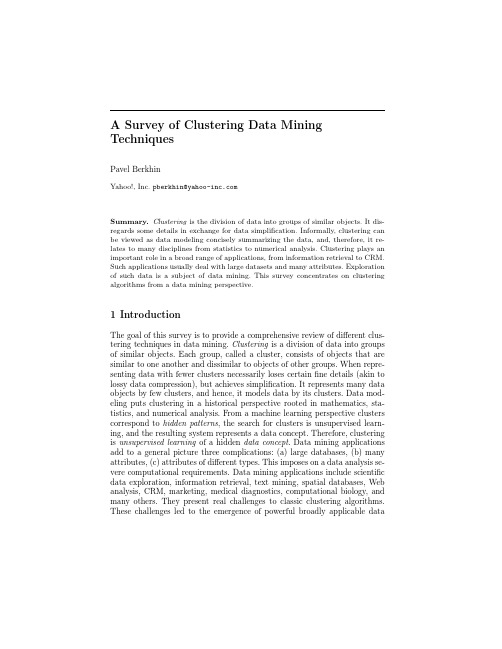
A Survey of Clustering Data Mining TechniquesPavel BerkhinYahoo!,Inc.pberkhin@Summary.Clustering is the division of data into groups of similar objects.It dis-regards some details in exchange for data simplifirmally,clustering can be viewed as data modeling concisely summarizing the data,and,therefore,it re-lates to many disciplines from statistics to numerical analysis.Clustering plays an important role in a broad range of applications,from information retrieval to CRM. Such applications usually deal with large datasets and many attributes.Exploration of such data is a subject of data mining.This survey concentrates on clustering algorithms from a data mining perspective.1IntroductionThe goal of this survey is to provide a comprehensive review of different clus-tering techniques in data mining.Clustering is a division of data into groups of similar objects.Each group,called a cluster,consists of objects that are similar to one another and dissimilar to objects of other groups.When repre-senting data with fewer clusters necessarily loses certainfine details(akin to lossy data compression),but achieves simplification.It represents many data objects by few clusters,and hence,it models data by its clusters.Data mod-eling puts clustering in a historical perspective rooted in mathematics,sta-tistics,and numerical analysis.From a machine learning perspective clusters correspond to hidden patterns,the search for clusters is unsupervised learn-ing,and the resulting system represents a data concept.Therefore,clustering is unsupervised learning of a hidden data concept.Data mining applications add to a general picture three complications:(a)large databases,(b)many attributes,(c)attributes of different types.This imposes on a data analysis se-vere computational requirements.Data mining applications include scientific data exploration,information retrieval,text mining,spatial databases,Web analysis,CRM,marketing,medical diagnostics,computational biology,and many others.They present real challenges to classic clustering algorithms. These challenges led to the emergence of powerful broadly applicable data2Pavel Berkhinmining clustering methods developed on the foundation of classic techniques.They are subject of this survey.1.1NotationsTo fix the context and clarify terminology,consider a dataset X consisting of data points (i.e.,objects ,instances ,cases ,patterns ,tuples ,transactions )x i =(x i 1,···,x id ),i =1:N ,in attribute space A ,where each component x il ∈A l ,l =1:d ,is a numerical or nominal categorical attribute (i.e.,feature ,variable ,dimension ,component ,field ).For a discussion of attribute data types see [106].Such point-by-attribute data format conceptually corresponds to a N ×d matrix and is used by a majority of algorithms reviewed below.However,data of other formats,such as variable length sequences and heterogeneous data,are not uncommon.The simplest subset in an attribute space is a direct Cartesian product of sub-ranges C = C l ⊂A ,C l ⊂A l ,called a segment (i.e.,cube ,cell ,region ).A unit is an elementary segment whose sub-ranges consist of a single category value,or of a small numerical bin.Describing the numbers of data points per every unit represents an extreme case of clustering,a histogram .This is a very expensive representation,and not a very revealing er driven segmentation is another commonly used practice in data exploration that utilizes expert knowledge regarding the importance of certain sub-domains.Unlike segmentation,clustering is assumed to be automatic,and so it is a machine learning technique.The ultimate goal of clustering is to assign points to a finite system of k subsets (clusters).Usually (but not always)subsets do not intersect,and their union is equal to a full dataset with the possible exception of outliersX =C 1 ··· C k C outliers ,C i C j =0,i =j.1.2Clustering Bibliography at GlanceGeneral references regarding clustering include [110],[205],[116],[131],[63],[72],[165],[119],[75],[141],[107],[91].A very good introduction to contem-porary data mining clustering techniques can be found in the textbook [106].There is a close relationship between clustering and many other fields.Clustering has always been used in statistics [10]and science [158].The clas-sic introduction into pattern recognition framework is given in [64].Typical applications include speech and character recognition.Machine learning clus-tering algorithms were applied to image segmentation and computer vision[117].For statistical approaches to pattern recognition see [56]and [85].Clus-tering can be viewed as a density estimation problem.This is the subject of traditional multivariate statistical estimation [197].Clustering is also widelyA Survey of Clustering Data Mining Techniques3 used for data compression in image processing,which is also known as vec-tor quantization[89].Datafitting in numerical analysis provides still another venue in data modeling[53].This survey’s emphasis is on clustering in data mining.Such clustering is characterized by large datasets with many attributes of different types. Though we do not even try to review particular applications,many important ideas are related to the specificfields.Clustering in data mining was brought to life by intense developments in information retrieval and text mining[52], [206],[58],spatial database applications,for example,GIS or astronomical data,[223],[189],[68],sequence and heterogeneous data analysis[43],Web applications[48],[111],[81],DNA analysis in computational biology[23],and many others.They resulted in a large amount of application-specific devel-opments,but also in some general techniques.These techniques and classic clustering algorithms that relate to them are surveyed below.1.3Plan of Further PresentationClassification of clustering algorithms is neither straightforward,nor canoni-cal.In reality,different classes of algorithms overlap.Traditionally clustering techniques are broadly divided in hierarchical and partitioning.Hierarchical clustering is further subdivided into agglomerative and divisive.The basics of hierarchical clustering include Lance-Williams formula,idea of conceptual clustering,now classic algorithms SLINK,COBWEB,as well as newer algo-rithms CURE and CHAMELEON.We survey these algorithms in the section Hierarchical Clustering.While hierarchical algorithms gradually(dis)assemble points into clusters (as crystals grow),partitioning algorithms learn clusters directly.In doing so they try to discover clusters either by iteratively relocating points between subsets,or by identifying areas heavily populated with data.Algorithms of thefirst kind are called Partitioning Relocation Clustering. They are further classified into probabilistic clustering(EM framework,al-gorithms SNOB,AUTOCLASS,MCLUST),k-medoids methods(algorithms PAM,CLARA,CLARANS,and its extension),and k-means methods(differ-ent schemes,initialization,optimization,harmonic means,extensions).Such methods concentrate on how well pointsfit into their clusters and tend to build clusters of proper convex shapes.Partitioning algorithms of the second type are surveyed in the section Density-Based Partitioning.They attempt to discover dense connected com-ponents of data,which areflexible in terms of their shape.Density-based connectivity is used in the algorithms DBSCAN,OPTICS,DBCLASD,while the algorithm DENCLUE exploits space density functions.These algorithms are less sensitive to outliers and can discover clusters of irregular shape.They usually work with low-dimensional numerical data,known as spatial data. Spatial objects could include not only points,but also geometrically extended objects(algorithm GDBSCAN).4Pavel BerkhinSome algorithms work with data indirectly by constructing summaries of data over the attribute space subsets.They perform space segmentation and then aggregate appropriate segments.We discuss them in the section Grid-Based Methods.They frequently use hierarchical agglomeration as one phase of processing.Algorithms BANG,STING,WaveCluster,and FC are discussed in this section.Grid-based methods are fast and handle outliers well.Grid-based methodology is also used as an intermediate step in many other algorithms (for example,CLIQUE,MAFIA).Categorical data is intimately connected with transactional databases.The concept of a similarity alone is not sufficient for clustering such data.The idea of categorical data co-occurrence comes to the rescue.The algorithms ROCK,SNN,and CACTUS are surveyed in the section Co-Occurrence of Categorical Data.The situation gets even more aggravated with the growth of the number of items involved.To help with this problem the effort is shifted from data clustering to pre-clustering of items or categorical attribute values. Development based on hyper-graph partitioning and the algorithm STIRR exemplify this approach.Many other clustering techniques are developed,primarily in machine learning,that either have theoretical significance,are used traditionally out-side the data mining community,or do notfit in previously outlined categories. The boundary is blurred.In the section Other Developments we discuss the emerging direction of constraint-based clustering,the important researchfield of graph partitioning,and the relationship of clustering to supervised learning, gradient descent,artificial neural networks,and evolutionary methods.Data Mining primarily works with large databases.Clustering large datasets presents scalability problems reviewed in the section Scalability and VLDB Extensions.Here we talk about algorithms like DIGNET,about BIRCH and other data squashing techniques,and about Hoffding or Chernoffbounds.Another trait of real-life data is high dimensionality.Corresponding de-velopments are surveyed in the section Clustering High Dimensional Data. The trouble comes from a decrease in metric separation when the dimension grows.One approach to dimensionality reduction uses attributes transforma-tions(DFT,PCA,wavelets).Another way to address the problem is through subspace clustering(algorithms CLIQUE,MAFIA,ENCLUS,OPTIGRID, PROCLUS,ORCLUS).Still another approach clusters attributes in groups and uses their derived proxies to cluster objects.This double clustering is known as co-clustering.Issues common to different clustering methods are overviewed in the sec-tion General Algorithmic Issues.We talk about assessment of results,de-termination of appropriate number of clusters to build,data preprocessing, proximity measures,and handling of outliers.For reader’s convenience we provide a classification of clustering algorithms closely followed by this survey:•Hierarchical MethodsA Survey of Clustering Data Mining Techniques5Agglomerative AlgorithmsDivisive Algorithms•Partitioning Relocation MethodsProbabilistic ClusteringK-medoids MethodsK-means Methods•Density-Based Partitioning MethodsDensity-Based Connectivity ClusteringDensity Functions Clustering•Grid-Based Methods•Methods Based on Co-Occurrence of Categorical Data•Other Clustering TechniquesConstraint-Based ClusteringGraph PartitioningClustering Algorithms and Supervised LearningClustering Algorithms in Machine Learning•Scalable Clustering Algorithms•Algorithms For High Dimensional DataSubspace ClusteringCo-Clustering Techniques1.4Important IssuesThe properties of clustering algorithms we are primarily concerned with in data mining include:•Type of attributes algorithm can handle•Scalability to large datasets•Ability to work with high dimensional data•Ability tofind clusters of irregular shape•Handling outliers•Time complexity(we frequently simply use the term complexity)•Data order dependency•Labeling or assignment(hard or strict vs.soft or fuzzy)•Reliance on a priori knowledge and user defined parameters •Interpretability of resultsRealistically,with every algorithm we discuss only some of these properties. The list is in no way exhaustive.For example,as appropriate,we also discuss algorithms ability to work in pre-defined memory buffer,to restart,and to provide an intermediate solution.6Pavel Berkhin2Hierarchical ClusteringHierarchical clustering builds a cluster hierarchy or a tree of clusters,also known as a dendrogram.Every cluster node contains child clusters;sibling clusters partition the points covered by their common parent.Such an ap-proach allows exploring data on different levels of granularity.Hierarchical clustering methods are categorized into agglomerative(bottom-up)and divi-sive(top-down)[116],[131].An agglomerative clustering starts with one-point (singleton)clusters and recursively merges two or more of the most similar clusters.A divisive clustering starts with a single cluster containing all data points and recursively splits the most appropriate cluster.The process contin-ues until a stopping criterion(frequently,the requested number k of clusters) is achieved.Advantages of hierarchical clustering include:•Flexibility regarding the level of granularity•Ease of handling any form of similarity or distance•Applicability to any attribute typesDisadvantages of hierarchical clustering are related to:•Vagueness of termination criteria•Most hierarchical algorithms do not revisit(intermediate)clusters once constructed.The classic approaches to hierarchical clustering are presented in the sub-section Linkage Metrics.Hierarchical clustering based on linkage metrics re-sults in clusters of proper(convex)shapes.Active contemporary efforts to build cluster systems that incorporate our intuitive concept of clusters as con-nected components of arbitrary shape,including the algorithms CURE and CHAMELEON,are surveyed in the subsection Hierarchical Clusters of Arbi-trary Shapes.Divisive techniques based on binary taxonomies are presented in the subsection Binary Divisive Partitioning.The subsection Other Devel-opments contains information related to incremental learning,model-based clustering,and cluster refinement.In hierarchical clustering our regular point-by-attribute data representa-tion frequently is of secondary importance.Instead,hierarchical clustering frequently deals with the N×N matrix of distances(dissimilarities)or sim-ilarities between training points sometimes called a connectivity matrix.So-called linkage metrics are constructed from elements of this matrix.The re-quirement of keeping a connectivity matrix in memory is unrealistic.To relax this limitation different techniques are used to sparsify(introduce zeros into) the connectivity matrix.This can be done by omitting entries smaller than a certain threshold,by using only a certain subset of data representatives,or by keeping with each point only a certain number of its nearest neighbors(for nearest neighbor chains see[177]).Notice that the way we process the original (dis)similarity matrix and construct a linkage metric reflects our a priori ideas about the data model.A Survey of Clustering Data Mining Techniques7With the(sparsified)connectivity matrix we can associate the weighted connectivity graph G(X,E)whose vertices X are data points,and edges E and their weights are defined by the connectivity matrix.This establishes a connection between hierarchical clustering and graph partitioning.One of the most striking developments in hierarchical clustering is the algorithm BIRCH.It is discussed in the section Scalable VLDB Extensions.Hierarchical clustering initializes a cluster system as a set of singleton clusters(agglomerative case)or a single cluster of all points(divisive case) and proceeds iteratively merging or splitting the most appropriate cluster(s) until the stopping criterion is achieved.The appropriateness of a cluster(s) for merging or splitting depends on the(dis)similarity of cluster(s)elements. This reflects a general presumption that clusters consist of similar points.An important example of dissimilarity between two points is the distance between them.To merge or split subsets of points rather than individual points,the dis-tance between individual points has to be generalized to the distance between subsets.Such a derived proximity measure is called a linkage metric.The type of a linkage metric significantly affects hierarchical algorithms,because it re-flects a particular concept of closeness and connectivity.Major inter-cluster linkage metrics[171],[177]include single link,average link,and complete link. The underlying dissimilarity measure(usually,distance)is computed for every pair of nodes with one node in thefirst set and another node in the second set.A specific operation such as minimum(single link),average(average link),or maximum(complete link)is applied to pair-wise dissimilarity measures:d(C1,C2)=Op{d(x,y),x∈C1,y∈C2}Early examples include the algorithm SLINK[199],which implements single link(Op=min),Voorhees’method[215],which implements average link (Op=Avr),and the algorithm CLINK[55],which implements complete link (Op=max).It is related to the problem offinding the Euclidean minimal spanning tree[224]and has O(N2)complexity.The methods using inter-cluster distances defined in terms of pairs of nodes(one in each respective cluster)are called graph methods.They do not use any cluster representation other than a set of points.This name naturally relates to the connectivity graph G(X,E)introduced above,because every data partition corresponds to a graph partition.Such methods can be augmented by so-called geometric methods in which a cluster is represented by its central point.Under the assumption of numerical attributes,the center point is defined as a centroid or an average of two cluster centroids subject to agglomeration.It results in centroid,median,and minimum variance linkage metrics.All of the above linkage metrics can be derived from the Lance-Williams updating formula[145],d(C iC j,C k)=a(i)d(C i,C k)+a(j)d(C j,C k)+b·d(C i,C j)+c|d(C i,C k)−d(C j,C k)|.8Pavel BerkhinHere a,b,c are coefficients corresponding to a particular linkage.This formula expresses a linkage metric between a union of the two clusters and the third cluster in terms of underlying nodes.The Lance-Williams formula is crucial to making the dis(similarity)computations feasible.Surveys of linkage metrics can be found in [170][54].When distance is used as a base measure,linkage metrics capture inter-cluster proximity.However,a similarity-based view that results in intra-cluster connectivity considerations is also used,for example,in the original average link agglomeration (Group-Average Method)[116].Under reasonable assumptions,such as reducibility condition (graph meth-ods satisfy this condition),linkage metrics methods suffer from O N 2 time complexity [177].Despite the unfavorable time complexity,these algorithms are widely used.As an example,the algorithm AGNES (AGlomerative NESt-ing)[131]is used in S-Plus.When the connectivity N ×N matrix is sparsified,graph methods directly dealing with the connectivity graph G can be used.In particular,hierarchical divisive MST (Minimum Spanning Tree)algorithm is based on graph parti-tioning [116].2.1Hierarchical Clusters of Arbitrary ShapesFor spatial data,linkage metrics based on Euclidean distance naturally gener-ate clusters of convex shapes.Meanwhile,visual inspection of spatial images frequently discovers clusters with curvy appearance.Guha et al.[99]introduced the hierarchical agglomerative clustering algo-rithm CURE (Clustering Using REpresentatives).This algorithm has a num-ber of novel features of general importance.It takes special steps to handle outliers and to provide labeling in assignment stage.It also uses two techniques to achieve scalability:data sampling (section 8),and data partitioning.CURE creates p partitions,so that fine granularity clusters are constructed in parti-tions first.A major feature of CURE is that it represents a cluster by a fixed number,c ,of points scattered around it.The distance between two clusters used in the agglomerative process is the minimum of distances between two scattered representatives.Therefore,CURE takes a middle approach between the graph (all-points)methods and the geometric (one centroid)methods.Single and average link closeness are replaced by representatives’aggregate closeness.Selecting representatives scattered around a cluster makes it pos-sible to cover non-spherical shapes.As before,agglomeration continues until the requested number k of clusters is achieved.CURE employs one additional trick:originally selected scattered points are shrunk to the geometric centroid of the cluster by a user-specified factor α.Shrinkage suppresses the affect of outliers;outliers happen to be located further from the cluster centroid than the other scattered representatives.CURE is capable of finding clusters of different shapes and sizes,and it is insensitive to outliers.Because CURE uses sampling,estimation of its complexity is not straightforward.For low-dimensional data authors provide a complexity estimate of O (N 2sample )definedA Survey of Clustering Data Mining Techniques9 in terms of a sample size.More exact bounds depend on input parameters: shrink factorα,number of representative points c,number of partitions p,and a sample size.Figure1(a)illustrates agglomeration in CURE.Three clusters, each with three representatives,are shown before and after the merge and shrinkage.Two closest representatives are connected.While the algorithm CURE works with numerical attributes(particularly low dimensional spatial data),the algorithm ROCK developed by the same researchers[100]targets hierarchical agglomerative clustering for categorical attributes.It is reviewed in the section Co-Occurrence of Categorical Data.The hierarchical agglomerative algorithm CHAMELEON[127]uses the connectivity graph G corresponding to the K-nearest neighbor model spar-sification of the connectivity matrix:the edges of K most similar points to any given point are preserved,the rest are pruned.CHAMELEON has two stages.In thefirst stage small tight clusters are built to ignite the second stage.This involves a graph partitioning[129].In the second stage agglomer-ative process is performed.It utilizes measures of relative inter-connectivity RI(C i,C j)and relative closeness RC(C i,C j);both are locally normalized by internal interconnectivity and closeness of clusters C i and C j.In this sense the modeling is dynamic:it depends on data locally.Normalization involves certain non-obvious graph operations[129].CHAMELEON relies heavily on graph partitioning implemented in the library HMETIS(see the section6). Agglomerative process depends on user provided thresholds.A decision to merge is made based on the combinationRI(C i,C j)·RC(C i,C j)αof local measures.The algorithm does not depend on assumptions about the data model.It has been proven tofind clusters of different shapes,densities, and sizes in2D(two-dimensional)space.It has a complexity of O(Nm+ Nlog(N)+m2log(m),where m is the number of sub-clusters built during the first initialization phase.Figure1(b)(analogous to the one in[127])clarifies the difference with CURE.It presents a choice of four clusters(a)-(d)for a merge.While CURE would merge clusters(a)and(b),CHAMELEON makes intuitively better choice of merging(c)and(d).2.2Binary Divisive PartitioningIn linguistics,information retrieval,and document clustering applications bi-nary taxonomies are very useful.Linear algebra methods,based on singular value decomposition(SVD)are used for this purpose in collaborativefilter-ing and information retrieval[26].Application of SVD to hierarchical divisive clustering of document collections resulted in the PDDP(Principal Direction Divisive Partitioning)algorithm[31].In our notations,object x is a docu-ment,l th attribute corresponds to a word(index term),and a matrix X entry x il is a measure(e.g.TF-IDF)of l-term frequency in a document x.PDDP constructs SVD decomposition of the matrix10Pavel Berkhin(a)Algorithm CURE (b)Algorithm CHAMELEONFig.1.Agglomeration in Clusters of Arbitrary Shapes(X −e ¯x ),¯x =1Ni =1:N x i ,e =(1,...,1)T .This algorithm bisects data in Euclidean space by a hyperplane that passes through data centroid orthogonal to the eigenvector with the largest singular value.A k -way split is also possible if the k largest singular values are consid-ered.Bisecting is a good way to categorize documents and it yields a binary tree.When k -means (2-means)is used for bisecting,the dividing hyperplane is orthogonal to the line connecting the two centroids.The comparative study of SVD vs.k -means approaches [191]can be used for further references.Hier-archical divisive bisecting k -means was proven [206]to be preferable to PDDP for document clustering.While PDDP or 2-means are concerned with how to split a cluster,the problem of which cluster to split is also important.Simple strategies are:(1)split each node at a given level,(2)split the cluster with highest cardinality,and,(3)split the cluster with the largest intra-cluster variance.All three strategies have problems.For a more detailed analysis of this subject and better strategies,see [192].2.3Other DevelopmentsOne of early agglomerative clustering algorithms,Ward’s method [222],is based not on linkage metric,but on an objective function used in k -means.The merger decision is viewed in terms of its effect on the objective function.The popular hierarchical clustering algorithm for categorical data COB-WEB [77]has two very important qualities.First,it utilizes incremental learn-ing.Instead of following divisive or agglomerative approaches,it dynamically builds a dendrogram by processing one data point at a time.Second,COB-WEB is an example of conceptual or model-based learning.This means that each cluster is considered as a model that can be described intrinsically,rather than as a collection of points assigned to it.COBWEB’s dendrogram is calleda classification tree.Each tree node(cluster)C is associated with the condi-tional probabilities for categorical attribute-values pairs,P r(x l=νlp|C),l=1:d,p=1:|A l|.This easily can be recognized as a C-specific Na¨ıve Bayes classifier.During the classification tree construction,every new point is descended along the tree and the tree is potentially updated(by an insert/split/merge/create op-eration).Decisions are based on the category utility[49]CU{C1,...,C k}=1j=1:kCU(C j)CU(C j)=l,p(P r(x l=νlp|C j)2−(P r(x l=νlp)2.Category utility is similar to the GINI index.It rewards clusters C j for in-creases in predictability of the categorical attribute valuesνlp.Being incre-mental,COBWEB is fast with a complexity of O(tN),though it depends non-linearly on tree characteristics packed into a constant t.There is a similar incremental hierarchical algorithm for all numerical attributes called CLAS-SIT[88].CLASSIT associates normal distributions with cluster nodes.Both algorithms can result in highly unbalanced trees.Chiu et al.[47]proposed another conceptual or model-based approach to hierarchical clustering.This development contains several different use-ful features,such as the extension of scalability preprocessing to categori-cal attributes,outliers handling,and a two-step strategy for monitoring the number of clusters including BIC(defined below).A model associated with a cluster covers both numerical and categorical attributes and constitutes a blend of Gaussian and multinomial models.Denote corresponding multivari-ate parameters byθ.With every cluster C we associate a logarithm of its (classification)likelihoodl C=x i∈Clog(p(x i|θ))The algorithm uses maximum likelihood estimates for parameterθ.The dis-tance between two clusters is defined(instead of linkage metric)as a decrease in log-likelihoodd(C1,C2)=l C1+l C2−l C1∪C2caused by merging of the two clusters under consideration.The agglomerative process continues until the stopping criterion is satisfied.As such,determina-tion of the best k is automatic.This algorithm has the commercial implemen-tation(in SPSS Clementine).The complexity of the algorithm is linear in N for the summarization phase.Traditional hierarchical clustering does not change points membership in once assigned clusters due to its greedy approach:after a merge or a split is selected it is not refined.Though COBWEB does reconsider its decisions,its。

Package‘mvna’October13,2022Title Nelson-Aalen Estimator of the Cumulative Hazard in MultistateModelsVersion2.0.1Author Arthur AllignolDescription Computes the Nelson-Aalen estimator of the cumulative transition hazard for arbi-trary Markov multistate models<ISBN:978-0-387-68560-1>.Maintainer Arthur Allignol<*************************>License MIT+file LICENSEImports latticeNeedsCompilation yesRepository CRANDate/Publication2017-09-1123:21:40UTCR topics documented:abortion (2)lines.mvna (2)mvna (4)plot.mvna (6)predict.mvna (8)print.mvna (10)sir.adm (11)sir.cont (12)summary.mvna (14)xyplot.mvna (15)Index171abortion Pregnancies exposed to coumarin derivativesDescriptionOutcomes of pregnancies exposed to coumarin derivatives.The aim is to investigate whether ex-position to coumarin derivatives increases the probability of spontaneous abortions.Apart from spontaneous abortion,pregnancy may end in induced abortion or live birth.Moreover,data are left-truncated as women usually enter the study several weeks after conception.Usagedata(abortion)FormatA data frame with1186observations on the following5variables.id Identification numberentry Entry times into the cohortexit Event timesgroup Group.0:control,1:exposed to coumarin derivativescause Cause of failure.1:induced abortion,2:life birth,3:spontaneous abortionSourceMeiester,R.and Schaefer,C(2008).Statistical methods for estimating the probability of sponta-neous abortion in observational studies–Analyzing pregnancies exposed to coumarin derivatives.Reproductive Toxicology,26,31–35Examplesdata(abortion)lines.mvna Lines method for’mvna’objectsDescriptionLines method for mvna objects.Usage##S3method for class mvnalines(x,tr.choice,col=1,lty,conf.int=FALSE,level=0.95,var.type=c("aalen","greenwood"),ci.fun=c("log","linear","arcsin"),ci.col=col,ci.lty=3,...)Argumentsx An object of class mvna.tr.choice A character vector of the form c("from to","from to")specifying which tran-sitions should be displayed.By default,all the transition hazards are plotted.col A vector of colours.Default is black.lty A vector of line types.Default is1:number of transitions.conf.int Logical.Indicates whether to display pointwise confidence interval.Default is FALSE.level Level of the confidence interval.Default is0.95.var.type Specifies the variance estimator that should be used to compute the confidence interval.One of"aalen"or"greenwood".Default is"aalen".ci.fun Specifies the transformation applied to the confidence interval.Choices are"lin-ear","log","arcsin".Default is"log".ci.col Colours of the confidence interval lines.By default,ci.col equals col.ci.lty Line types for the confidence intervals.Default is3....Further arguments for lines.ValueNo value returned.Author(s)Arthur Allignol,<*************************>See Alsomvna,plot.mvnaExamplesdata(sir.adm)##data set transformationdata(sir.adm)id<-sir.adm$idfrom<-sir.adm$pneuto<-ifelse(sir.adm$status==0,"cens",sir.adm$status+1)times<-sir.adm$time4mvnadat.sir<-data.frame(id,from,to,time=times)##Possible transitionstra<-matrix(ncol=4,nrow=4,FALSE)tra[1:2,3:4]<-TRUEna.pneu<-mvna(dat.sir,c("0","1","2","3"),tra,"cens")plot(na.pneu,tr.choice=c("02"),conf.int=TRUE,col=1,lty=1,legend=FALSE)lines(na.pneu,tr.choice=c("12"),conf.int=TRUE,col=2,lty=1)mvna Nelson-Aalen estimator in multistate modelsDescriptionThis function computes the multivariate Nelson-Aalen estimator of the cumulative transition haz-ards in multistate models,that is,for each possible transition,it computes an estimate of the cumu-lative hazard.Usagemvna(data,s,tra,)Argumentsdata A data.frame of the form data.frame(id,from,to,time)or(id,from,to,entry,exit) id:patient idfrom:the state from where the transition occursto:the state to which a transition occurstime:time when a transition occursentry:entry time in a stateexit:exit time from a stateThis data.frame is transition-oriented,i.e.it contains one row per transition,andpossibly several rows per patient.Specifying an entry and exit time permits totake into account left-truncation.s A vector of character giving the states names.tra A quadratic matrix of logical values describing the possible transitions within the multistate model. A character giving the code for censored observations in the column to of data.If there is no censored observations in your data,put NULL.mvna5DetailsThis functions computes the Nelson-Aalen estimator as described in Anderson et al.(1993),along with the two variance estimators described in eq.(4.1.6)and(4.1.7)of Andersen et al.(1993)at each transition time.ValueReturns a list named after the possible transitions,e.g.if we define a multistate model with two possible transitions:from state0to state1,and from state0to state2,the returned list will have two parts named"01"and"02".Each part contains a data.frame with columns:na Nelson-Aalen estimates at each transition times.var.aalen Variance estimator given in eq.(4.1.6)of Andersen et al.(1993).var.greenwood Variance estimator given in eq.(4.1.7)of Andersen et al.(1993).time The transition times.The list also contains:time All the event times.n.risk A matrix giving the number at individual at risk in the transient states just before an event.n.event An array which gives the number of transitions at each event times.n.cens A matrix giving the number a censored observations at each event times.s The same as in the function call. The same as in the function call.trans A data frame,with columns from and to,that gives the possible transitions. NoteThe variance estimator(4.1.6)may overestimate the true variance,and the one defined eq.(4.1.7) may underestimate the true variance(see Klein(1991)and Andersen et al.(example IV.1.1,1993)), especially with small sample set.Klein(1991)recommends the use of the variance estimator of eq.(4.1.6,"aalen")because he found it to be less biased.Author(s)Arthur Allignol,<*************************>ReferencesAndersen,P.K.,Borgan,O.,Gill,R.D.and Keiding,N.(1993).Statistical models based on counting processes.Springer Series in Statistics.New York,NY:Springer.Beyersmann J,Allignol A,Schumacher M:Competing Risks and Multistate Models with R(Use R!),Springer Verlag,2012(Use R!)Klein,J.P.Small sample moments of some estimators of the variance of the Kaplan-Meier and Nelson-Aalen estimators.Scandinavian Journal of Statistics,18:333–340,1991.See Alsosir.adm,sir.contExamplesdata(sir.cont)#Modification for patients entering and leaving a state#at the same datesir.cont<-sir.cont[order(sir.cont$id,sir.cont$time),]for(i in2:nrow(sir.cont)){if(sir.cont$id[i]==sir.cont$id[i-1]){if(sir.cont$time[i]==sir.cont$time[i-1]){sir.cont$time[i-1]<-sir.cont$time[i-1]-0.5}}}#Matrix of logical giving the possible transitionstra<-matrix(ncol=3,nrow=3,FALSE)tra[1,2:3]<-TRUEtra[2,c(1,3)]<-TRUE#Computation of the Nelson-Aalen estimatesna<-mvna(sir.cont,c("0","1","2"),tra,"cens")#plotif(require(lattice))xyplot(na)###example with left-truncationdata(abortion)#Data set modification in order to be used by mvnanames(abortion)<-c("id","entry","exit","from","to")abortion$to<-abortion$to+1##computation of the matrix giving the possible transitions tra<-matrix(FALSE,nrow=5,ncol=5)tra[1:2,3:5]<-TRUEna.abortion<-mvna(abortion,as.character(0:4),tra,NULL) plot(na.abortion,tr.choice=c("04","14"),curvlab=c("Control","Exposed"),bty="n",legend.pos="topleft")plot.mvna Plot method for a mvna objectDescriptionPlot method for an object of class mvna.This function plots estimates of the cumulative transition hazards in one panel.Usage##S3method for class mvnaplot(x,tr.choice,xlab="Time",ylab="Cumulative Hazard",col=1,lty,xlim,ylim,conf.int=FALSE,level=0.95,var.type=c("aalen","greenwood"),ci.fun=c("log","linear","arcsin"),ci.col=col,ci.lty=3,legend=TRUE,legend.pos,curvlab,legend.bty="n",...)Argumentsx An object of class mvna.tr.choice A character vector of the form c("from to","from to")specifying which tran-sitions should be plotted.Default,all the cumulative transition hazards are plot-ted.xlab x-axis label.Default is"Time".ylab y-axis label.Default is"Cumulative Hazard".col Vector of colour.Default is black.lty Vector of line type.Default is1:number of transitionsxlim Limits of x-axis for the plotylim Limits of y-axis for the plotconf.int Logical.Whether to display pointwise confidence intervals.Default is FALSE.level Level of the pointwise confidence intervals.Default is0.95.var.type A character vector specifying the variance that should be used to compute the pointwise confidence intervals.Choices are"aalen"or"greenwood".Default is"aalen".ci.fun One of"log","linear"or"arcsin".Indicates which transformation to apply to the confidence intervals.ci.col Colour for the confidence intervals.By default,the colour specified by col is used.ci.lty Line type for the confidence intervals.Default is3.legend A logical specifying if a legend should be addedlegend.pos A vector giving the legend’s position.See legend for further details.curvlab A character or expression vector to appear in the legend.Default is the name of the transitions.legend.bty Box type for the legend....Further arguments for plot method.DetailsThis plot method permits to draw several cumulative transition hazards on the same panel.ValueNo value returnedAuthor(s)Arthur Allignol<*************************>See AlsomvnaExamplesdata(sir.cont)#Modification for patients entering and leaving a state#at the same datesir.cont<-sir.cont[order(sir.cont$id,sir.cont$time),]for(i in2:nrow(sir.cont)){if(sir.cont$id[i]==sir.cont$id[i-1]){if(sir.cont$time[i]==sir.cont$time[i-1]){sir.cont$time[i-1]<-sir.cont$time[i-1]-0.5}}}tra<-matrix(ncol=3,nrow=3,FALSE)tra[1,2:3]<-TRUEtra[2,c(1,3)]<-TRUEna.cont<-mvna(sir.cont,c("0","1","2"),tra,"cens")plot(na.cont,tr.choice=c("02","12"))predict.mvna Calculates Nelson-Aalen estimates at specified time-pointsDescriptionThis function gives the Nelson-Aalen estimates at time-points specified by the user.Usage##S3method for class mvnapredict(object,times,tr.choice,level=0.95,var.type=c("aalen","greenwood"),ci.fun=c("log","linear","arcsin"),...)Argumentsobject An object of class mvnatimes Time-points at which one wants the estimatestr.choice A vector of character giving for which transitions one wants estimates.By de-fault,the function will give the Nelson-Aalen estimates for all transitions.level Level of the pointwise confidence intervals.Default is0.95.var.type Variance estimator displayed and used to compute the pointwise confidence in-tervals.One of"aalen"or"greenwood".Default is"aalen".ci.fun Which transformation to apply for the confidence intervals.Choices are"linear", "log"or"arcsin".Default is"log"....Other arguments to predictValueReturns a list named after the possible transitions,e.g.if we define a multistate model with two possible transitions:from state0to state1,and from state0to state2,the returned list will have two parts named"01"and"02".Each part contains a data.frame with columns:times Time points specified by the user.na Nelson-Aalen estimates at the specified times.var.aalen or var.greenwoodDepending on what was specified in var.type.lower Lower bound of the pointwise confidence intervals.upper Upper bound.Author(s)Arthur Allignol,<*************************>ReferencesAndersen,P.K.,Borgan,O.,Gill,R.D.and Keiding,N.(1993).Statistical models based on counting processes.Springer Series in Statistics.New York,NY:Springer.See Alsomvna,summary.mvna10print.mvnaExamplesdata(sir.cont)#Modification for patients entering and leaving a state#at the same datesir.cont<-sir.cont[order(sir.cont$id,sir.cont$time),]for(i in2:nrow(sir.cont)){if(sir.cont$id[i]==sir.cont$id[i-1]){if(sir.cont$time[i]==sir.cont$time[i-1]){sir.cont$time[i-1]<-sir.cont$time[i-1]-0.5}}}#Matrix of logical giving the possible transitionstra<-matrix(ncol=3,nrow=3,FALSE)tra[1,2:3]<-TRUEtra[2,c(1,3)]<-TRUE#Computation of the Nelson-Aalen estimatesna<-mvna(sir.cont,c("0","1","2"),tra,"cens")#Using predictpredict(na,times=c(1,5,10,15))print.mvna Print method for’mvna’objectDescriptionPrint method for an object of class mvna.It prints estimates of the cumulative hazard along with estimates of the variance described in eq.(4.1.6)and(4.1.7)of Andersen et al.(1993)at several time points obtained with the quantile function.Usage##S3method for class mvnaprint(x,...)Argumentsx An object of class mvna...Other arguments for print methodValueNo value returned.sir.adm11Author(s)Arthur Allignol,<*******************************>See Alsomvnasir.adm Pneumonia on admission in intenive care unit patientsDescriptionPneumonia status on admission for intensive care unit(ICU)patients,a random sample from the SIR-3study.Usagedata(sir.adm)FormatThe data contains747rows and4variables:id:Randomly generated patient idpneu:Pneumonia indicator.0:No pneumonia,1:Pneumoniastatus Status indicator.0:censored observation,1:discharged,2:deadtime:Follow-up time in dayage:Age at inclusionsex:Sex.F for female and M for maleSourceBeyersmann,J.,Gastmeier,P.,Grundmann,H.,Baerwolff,S.,Geffers,C.,Behnke,M.,Rueden,H., and Schumacher,e of multistate models to assess prolongation of intensive care unit stay due to nosocomial infection.Infection Control and Hospital Epidemiology,27:493-499,2006. Examples#data set transformationdata(sir.adm)id<-sir.adm$idfrom<-sir.adm$pneuto<-ifelse(sir.adm$status==0,"cens",sir.adm$status+1)times<-sir.adm$timedat.sir<-data.frame(id,from,to,time=times)#Possible transitionstra<-matrix(ncol=4,nrow=4,FALSE)tra[1:2,3:4]<-TRUEna.pneu<-mvna(dat.sir,c("0","1","2","3"),tra,"cens")if(require("lattice")){xyplot(na.pneu,tr.choice=c("02","12","03","13"),aspect=1,strip=strip.custom(bg="white",factor.levels=c("No pneumonia on admission--Discharge","Pneumonia on admission--Discharge","No pneumonia on admission--Death","Pneumonia on admission--Death"),par.strip.text=list(cex=0.9)),scales=list(alternating=1),xlab="Days",ylab="Nelson-Aalen esimates")}sir.cont Ventilation status in intensive care unit patientsDescriptionTime-dependent ventilation status for intensive care unit(ICU)patients,a random sample from the SIR-3study.Usagedata(sir.cont)FormatA data frame with1141rows and6columns:id:Randomly generated patient idfrom:State from which a transition occursto:State to which a transition occurstime:Time when a transition occursage:Age at inclusionsex:Sex.F for female and M for maleThe possible states are:0:No ventilation1:Ventilation2:End of stay.And cens stands for censored observations.DetailsThis data frame consists in a random sample of the SIR-3cohort data.It focuses on the effect of ven-tilation on the length of stay(combined endpoint discharge/death).Ventilation status is considered as a transcient state in an illness-death model.The data frame is directly formated to be used with the mvna function,i.e.,it is transition-oriented with one row per transition.SourceBeyersmann,J.,Gastmeier,P.,Grundmann,H.,Baerwolff,S.,Geffers,C.,Behnke,M.,Rueden,H., and Schumacher,e of multistate models to assess prolongation of intensive care unit stay due to nosocomial infection.Infection Control and Hospital Epidemiology,27:493-499,2006. Examplesdata(sir.cont)#Matrix of possible transitionstra<-matrix(ncol=3,nrow=3,FALSE)tra[1,2:3]<-TRUEtra[2,c(1,3)]<-TRUE#Modification for patients entering and leaving a state#at the same datesir.cont<-sir.cont[order(sir.cont$id,sir.cont$time),]for(i in2:nrow(sir.cont)){if(sir.cont$id[i]==sir.cont$id[i-1]){if(sir.cont$time[i]==sir.cont$time[i-1]){sir.cont$time[i-1]<-sir.cont$time[i-1]-0.5}}}#Computation of the Nelson-Aalen estimatesna.cont<-mvna(sir.cont,c("0","1","2"),tra,"cens")if(require("lattice")){xyplot(na.cont,tr.choice=c("02","12"),aspect=1,strip=strip.custom(bg="white",factor.levels=c("No ventilation--Discharge/Death","Ventilation--Discharge/Death"),par.strip.text=list(cex=0.9)),scales=list(alternating=1),xlab="Days",ylab="Nelson-Aalen estimates")}14summary.mvna summary.mvna Summary method for objects of class’mvna’DescriptionSummary method for mvna objects.The function returns a list containing the cumulative transition hazards,variance and other informations.Usage##S3method for class mvnasummary(object,level=0.95,var.type=c("aalen","greenwood"),ci.fun=c("log","linear","arcsin"),...)##S3method for class mvnaprint.summary(x,...)Argumentsobject An object of class mvna.level Level of the pointwise confidence interval.Default is0.95.var.type Which of the"aalen"or"greenwood"variance estimator should be displayed and used to compute the pointwise confidence intervals.Default is"aalen".ci.fun Which transformation to apply to the confidence intervals.One of"linear", "log","arcsin".Default is"log"....Further arguments.x An object of class summary.mvna.ValueReturns an object of class mvna which is a list of data frames named after the possible transitions.Each data frame contains the following columns:time Event times at which the cumulative hazards are estimated.na Estimated cumulative transition hazards.var.aalen or var.greenwoodVariance estimates.The name depends on the var.type argument.Default willbe var.aalen.lower Lower bound of the pointwise confidence interval.upper Upper bound.n.risk Number of individuals at risk of experiencing an event just before t.n.event Number of transitions at time t.Author(s)Arthur Allignol,<*************************>See AlsomvnaExamplesdata(sir.adm)##data set transformationdata(sir.adm)id<-sir.adm$idfrom<-sir.adm$pneuto<-ifelse(sir.adm$status==0,"cens",sir.adm$status+1)times<-sir.adm$timedat.sir<-data.frame(id,from,to,time=times)##Possible transitionstra<-matrix(ncol=4,nrow=4,FALSE)tra[1:2,3:4]<-TRUEna.pneu<-mvna(dat.sir,c("0","1","2","3"),tra,"cens")summ.na.pneu<-summary(na.pneu)##cumulative hazard for0->2transition:summ.na.pneu$"02"$naxyplot.mvna Panel plots for object of class’mvna’Descriptionxyplot function for objects of class mvna.Estimates of the cumulative hazards are plotted as a function of time for all the transitions specified by the user.The function can also plot several types of pointwise confidence interval(see Andersen et al.(1993)p.208).Usage##S3method for class mvnaxyplot(x,data=NULL,xlab="Time",ylab="Cumulative Hazard",tr.choice="all",conf.int=TRUE,var.type=c("aalen","greenwood"),ci.fun=c("log","linear","arcsin"),level=0.95,col=c(1,1,1),lty=c(1,3,3),ci.type=c(1,2),...)Argumentsx An object of class mvna.data Useless.xlab x-axis label.Default is"Time".ylab y-axis label.Default is"Cumulative Hazard"tr.choice A character vector of the form c("from to","from to")specifying which tran-sitions should be plotted.Default is"all".conf.int A logical whether plot pointwise confidence interval.Default is TRUEvar.type One of"aalen"or"greenwood".Specifies which variance estimator is used to compute the confidence intervals.ci.fun One of"log","linear"or"arcsin".Indicates the transformation applied to the pointwise confidence intervals.Default is"log".level Level of the confidence interval.Default is0.95.col Vector of colour for the plot.Default is black.lty Vector of line type.Default is c(1,3,3).ci.type DEPRECATED...Other arguments for xyplot.ValueAn object of class trellis.NoteThese plots are highly customizable,see Lattice and xyplot.For example,if one want to change strip background color and the title of each strip,it can be added’strip=strip.custom(bg="a color",factor.levels="a title","another title")’.One can use’aspect="1"’to get the size of the panels isometric.Author(s)Arthur Allignol,<*******************************>ReferencesAndersen,P.K.,Borgan,O.,Gill,R.D.and Keiding,N.(1993).Statistical models based on counting processes.Springer Series in Statistics.New York,NY:Springer.Deepayan Sarkar(2006).lattice:Lattice Graphics.R package version0.13-8.See Alsoxyplot,mvna,sir.adm,sir.contIndex∗aplotlines.mvna,2∗datasetsabortion,2sir.adm,11sir.cont,12∗hplotplot.mvna,6xyplot.mvna,15∗printprint.mvna,10∗survivalabortion,2lines.mvna,2mvna,4plot.mvna,6predict.mvna,8print.mvna,10sir.adm,11sir.cont,12summary.mvna,14xyplot.mvna,15abortion,2Lattice,16legend,7lines.mvna,2mvna,3,4,8,9,11,15,16plot.mvna,3,6predict.mvna,8print.mvna,10print.summary.mvna(summary.mvna),14sir.adm,6,11,16sir.cont,6,12,16summary.mvna,9,14xyplot,16xyplot.mvna,1517。

TR473677Procedural and Automated Workflows in Alias for AutomotiveMichael Günther-GeffersAutodeskDescriptionIn this class we will go over some of the new features in Alias software that can help inprocedural modeling techniques, and tools that you can create with scripts to be driven through Dynamo software. Dynamo is a visual programming platform that you can use to create custom algorithms to process data and generate geometry. Since version 2019, we have had anintegration of Dynamo in our Alias line of products (Concept, Surface, and AutoStudio). With the latest release of 2021, we have included Dynamo player, which enables anyone to run scripts and capitalize on the power of these tools to improve workflows and processes to save time and effort.SpeakerWhile Michael Günther-Geffers achieved his diploma inmathematics and computers in 2006, he has already been intouch with CAD programs for the automotive industry since theyear 2000.He started as a quality assurance engineer for ICEM Surf, andlater also tested its integration into Catia V5 (ICEM ShapeDesign at that time, later renamed to ICEM Catia).In 2010 he joined Virtual Shape Research (VSR) as a QA,support and content creator for a rendering and class A pluginfor Rhinoceros 3D.Joining Autodesk with the acquisition of VSR in 2013, he thenworked as a UX designer for SpeedForm and later Alias.2018 he transitioned back to the QA role, becoming the technical lead for the testing of Alias. Since 2019 he is the QA manager for all automotive products (Alias, VRED, SketchBook, Shotgun), and became a free time enthusiast in using Dynamo and writing scripts to solve problems for Alias users. Learning Objectives • Understand in which areas Dynamo and the Dynamo Player can be utilized• Learn how to make a Dynamo Script work for the Dynamo PlayerApplication areas for DynamoDynamo and the Dynamo Player can be used in much more areas than probably most people are aware of. This class goes over several categories of possible appliances and shows you example scripts for each of them.Alias 2021.2 comes with 14 Dynamo Player sample scripts, which demonstrate how Dynamo can be used to create your own tools. Each of these scripts could have been written by anyone who understands Dynamo. There is no dependency of them to the Autodesk development team. You can find those scripts on t he What’s New Shelf, which is accessible under “Help –What’s New –What’s New Shelf”:TemplatesWhenever you have a reoccurring task of creating objects of a certain shape and/or structure, or modifying them in a way, chances are not too bad that this approach could be captured in a Dynamo script. If that is the case, you can create a Dynamo Player tool, which can then be saved onto your shelf in Alias. This allows you to easily skip over the reoccurring work, e.g. like creating a base shape of certain dimensions, as Dynamo does this for you. You simply start using your tailored tool in Alias. When doing so, you don’t have to go to Dynamo, or even know that Dynamo is utilized in the background. This allows each user to optimize his or her workflow, saving precious time which can be used to create more and better models.Nurbs TemplatesA typical reoccurring shape in the automotive contextis a tire. While it is true that the shape of a tire can beeasily created by rotating a profile curve by 360degrees, having a Dynamo Player tool available forthis shape comes with several advantages. You candirectly enter “real life” parameters like the rim size orthe width of the tire. At the same time, you can justsimply move sliders to adjust the global shape, toachieve the wanted result very quickly.The tire script takes construction points as input, tothen create the Nurbs tire(s) at the wantedposition(s).Subdiv TemplatesSubdiv templates can be even morepowerful than Nurbs, as Dynamooffers a lot of notes to create andmodify subdiv geometry. A goodexample for this is the Wheel Archtool. As a lot of car designers startwith the wheel arches and the sideshape of a car, the Wheel Arch tool provides an easy way to create two wheel arches with specified radius and amount of faces. Both wheel arches are bridged together, to form the side shape of a car, again with user defined values like distance and amount of faces. This template can save the first 10-15 minutes of modeling in the beginning of each new subdiv car design.Similar tools could be created for other objects which have a defined shape every time, like steering wheels, seats, and such.Templates using geometry inputProbably most templates would take defined numerical values as input, e.g. the radius of the wheel arch, or the width of a tire. But you should also be aware that it sometimes might make sense to drive the geometry created by your templates by Alias geometry. This is for example the case when working visually, like when you want to create a 3D model from a 2D sketch. In this case, you don’t have technical data like the length of the car. Instead you would like to drive your base shape by simply dragging your mouse. One way to achieve this is letting the user create the needed geometry, and then select it for the Dynamo Player script. Another way is to provide the user with a wire file, which already has the needed geometry input in place.The wheel arch tool has a version which does exactly that. Instead of using the Dynamo Player, you can import a sample wire file. This file already has the template geometry created (in this case, the bridged wheel arches creating the side shape of a car). The dimension of this shape is controlled by Alias geometry, in this case Nurbs curves. By that, the user can simply move the curves to the needed positions, and move e.g. CVs as needed, looking at a displayed background canvas, to fit the wanted dimensions.To check out thi s workflow, click on the “2021” tab of the What’s New Shelf, and click on the icon all on the right. A file browser opens, pointing at the location “C:\ProgramFiles\Autodesk\AliasAutoStudio2021.2\Dynamo\Sample Files”. Navigate into the “Subdiv Wheel Arch” folder, and double click on the wire file Subdiv-Wheel-Arch-2021.2.4.wire to import it.Similar as in this wire file, every user who wants to drive his template object by Alias geometry, can simply save a wire file, which has the wanted Dynamo script referenced. Since Alias 2021, dragging and dropping the “import wire file” tool onto a shelf remembers the last path being used. This way, with very few clicks, you can import a wire file to drive your template creation with geometry instead of numerical parameters. You can see this workflow in the following video:https:///watch?v=nOXOC0qkO3kSubdiv tools using the T-Spline library in DynamoThe T-Spline library is a library which is often used in the background for a lot of Alias subdiv operations. While the resulting object type of T-Spline nodes in Dynamo is a T-Spline, it will be converted to a subdiv when it is sent to Alias.T-Spline is a more powerful type of geometry than a subdivision object. As this comes with a cost of performance, and as having two different types of subdivision objects would have been likely a confusing user experience, Alias introduced only subdivision surfaces 1.5 years ago. Nevertheless, the T-Spline library is very powerful. In Dynamo, a lot of nodes allow you to create and modify T-Spline objects, to then send them to Alias as subdivision objects.In Dynamo, the T-Spline nod es can be found in the tree on the left under “Geometry – TS pline”. In the beginning, probably the nodes creating complete bodies are most useful to you. Those nodes can be found in the sub section “TSplineSurface”.Primitive toolsUtilizing the T-Spline library in Dynamo, it was veryeasy to add the functionality to create subdivcones, spheres, quad balls and torus as DynamoPlayer tools in Alias. Depending on your needs andpreferences, you might want to add differentversions of those tools. For example, the currentsubdiv box creation tool in Alias only allows you tochoose the spans for the X, Y and Z direction, thedimensions are controlled dynamically. If youprefer to define width, length and height of the boxnumerically instead, you could simply use theDynamo node TSplineSurface.ByBoxLengths, andcreate a Dynamo Player tool from it. An examplelike this will be shown in the second section of this handout.General toolsThe T-Spline library in Dynamo also offers morecomplex subdiv generation nodes, like the Sweep,the Revolve and the Pipe tool. While the Sweepand Revolve tool work rather straight forward andcan be seen as the subdiv pendants of thecorresponding Nurbs tools, the pipe tool deservesa second look. When the input curves aredisconnected, it will simply create a pipe for eachcurve, as expected. But if the curves areconnected, it will take care of the subdiv topologyat the meeting points, creating one closed subdivbody out of all connected curves.Creating distributed geometryOf course, Dynamo can also be used in its well-known area of creating and placing a lot of objects in an easy fashion. With the “Nurbs-Hexagon-Pattern” sample script, people can try different versions of a hexagonal pattern, which will be distributed over the input surface the user chooses:It is worth pointing out that you can also apply easier, self-written scripts with great visual effects. The following script has been created after 2021.2 was shipped, so it’s not part of the sample scripts of this release. It simply distributes a closed subdiv body along a curve, in a controllable nonlinear way. It also allows a staggered rotation of that body along the guide curve. This creates a nice visual effect, and saved a good amount of modeling time, while the script itself was written in about an hour:Ease of useThe Dynamo Player allows you to tailor your tools, as you are now in control about which parameters to expose, how to name them, and what the default parameter range is. E.g. you can now create your own circle tool, which takes the radius of the circle as a numerical input value. This way, you don’t have to create the circle, and then afterwards scale it in the information window, to achieve the wanted size. You can directly enter the wanted value. Modifying existing geometryAnother area of applying Dynamo scripts which might be easily overlooked is the ability to write your own “modification” tools. The quotation marks must be used, because Dynamo can’t directly work on the input geometry. But you can take the input, create a copy, and modify the copy in the needed way. When the original input is then deleted afterwards, you have effectively (in a way) modified your input.It is e.g. possible to write a script to align subdiv geometry perpendicularly to reference geometry, as you can see in this video:https://youtu.be/Ge5PInMRHs8?t=26Another way to use this is the sample morph script “Subdiv-Morph-between-2-Objects”, which is part of the What’s New Shelf. It takes two differently shaped su bdiv’s as an input, and then creates a third copy in between them, which is an intermediate shape of the two input bodies. With one single slider, you can then control if the new object shall be closer to the shape of the first, or the second input body, as you can see here:https://youtu.be/Jx531XHWFAg?t=76Be aware that both input bodies must have the same number of CVs, to allow the script to work. Ideally, they should be created via copy and paste, before they received their different shape. Import and Export operationsDynamo is also able to import and export several types of file formats, such as images, excel files, T-Spline formats (.tss and .tsm), text and CSV files. A Dynamo Player sample script which utilizes this is the “Export-to-tsm” tool. It allows the user to select a subdiv body, and then write it to disk, with a user given file path and file name. This is useful if you want to send Alias subdiv geometry to Fusion (Fusion can import the .tsm file format).Alias does not support the .tsm export functionality natively yet. In fact, this script has been written for an Autodesk employee, who needed a quick support of this data exchange. This is therefore a good example on how it is now possible to solve issues directly, without having to wait for a next Alias release.Making a Dynamo script work for the Dynamo PlayerIn general, each Dynamo script can become a Dynamo Player script, and therefore utilized as being a tool in Alias. Let’s create a new one from scratch. Start Alias and start the “normal” Dynamo tool. It can be found in the Palette, in the bottom right of the “Transform” tab. Keep the left mouse button pressed to expand the tools, and choose the “Dynamo” tool on the ri ght: After Dynamo has come up, click on “New”. We want to create a Dynamo Player tool for a circle, which allows the user to specify the radius directly on creation. So, the first thing we need to do, is to add a “Circle” no de. Right click into the grap hics area of Dynamo, and type “circle” into the upcoming search window:Choose the option ByCenterPointRadius. A node named Circle.ByCenterPointRadius appears. The needed inputs for this node are displayed on the left and named centerPoint and radius. The output of this node on the right is named Circle.Next thing we need are the nodes we want to gather the needed input from Alias. Right click in the graphics area of Dynamo, and type in “select”:Pick the “Select from Alias” option on the top of the lis t. A nod e named “Select from Alias” appears. To connect this node with the Circle node we created before, left mouse button click on the text Geometry, and then left mouse button click on the text centerPoint of the “Circle” node. As only points are suitab le inputs for a center point of the circle to be created, let’s limit the Alias selection to that object type. To do so, click on Unspecified in the “Select from Alias” note, and select the entry Point. This will set the selection filter of the Dynamo Player tool accordingly, when this script is used.Our last remaining needed input is a value for the radius. Right click again into the graphics area of Dynamo, and type in “slider”. Pick the “Number Slider” entry of the upcoming list. To connect this node wi th our “Circle” no de, left click on the >symbol on the right of the “Number Slider” no de, then left click on the text radius of the “Circle” no de.As we want this slider to show up in the Dynamo Player tool, we need to mark it accordingly. For that, right click on the “Number Slider”, and activate the option Is Input.Note that th is option is set by default for the “Select from Alias” no de, as the solely purpose of this node is to select something from Alias, so it always will be an input.Once the circle creation is complete, we want to send the geometry back to Alias. For this, right click into the graphics area from Dynamo, and type in “send”. Pick the “Send to Alias” entry. Left click on the text Circle of the “Circle” no de, then left click on the >icon on the left of the “Send to Alias” no de.A Dynamo script which sends geometry to Alias needs to be saved on disk before it can work. Reason for that is, that the Alias model needs to store the path to the Dynamo script. This can only happen, if the script exists somewhere on disk.Once you have saved your file, you can use it in the Dynamo Player. To do so, open the Dynamo Player in Alias. It’s also in the Transform tab of the Palette, in the bottom right, called dynply.Browse to your script which you have just saved, using the “…” icon in the Dynamo Player tool window:Once you have done that, you will notice that your Dynamo Player window has changed. It now shows the name of your saved script in the title, as well as the needed inputs (a point to select, and a radius to be given) in the lower section of the window:Let’s do some fine tuning, before saving this new tool to a shelf. Click on the “Edit in Dynamo” button, to edit the currently loaded script. We want the text “Select from Alias” to be “Select Center Point” instead. For this, in Dynamo, right mouse button click on the “Select from Alias” node, and pick “Rename node…”. In the upcoming window, change the name to “Select Center Point”.In addition to that, we want to change the text “Number Slider”, too. Right mouse button click on the number slider in Dynamo, pick “Rename node…”, and change the title to “Radius”.Save the script, and you will immediately see that the Dynamo Player tool window has adapted the texts.If you now drag and drop the Dynamo Player icon onto your own user defined shelf, you have created your own circle tool, which directly allows you to enter a radius open circle creation. For a more detailed description, and sample videos, check out the Alias online help on this topic:https:///view/ALIAS/2021/ENU/?guid=GUID-1E1BBB04-060B-4AC4-AD06-0CA8B539FE16。


桥梁工程指桥梁勘测、设计、施工、养护和检定等的工作过程,以及研究这一过程的科学和工程技术,它是土木工程的一个分支。
桥梁工程学的发展主要取决于交通运输对它的需要。
以下是搜索整理的关于桥梁工程英文参考文献,欢迎借鉴参考。
桥梁工程英文参考文献一:[1]Liam J. Butler,Weiwei Lin,Jinlong Xu,Niamh Gibbons,Mohammed Z. E. B. Elshafie,Campbell R. Middleton. Monitoring, Modeling, and Assessment of a Self-Sensing Railway Bridge during Construction[J]. Journal of Bridge Engineering,2018,23(10).[2]Reza Akbari. Accelerated Construction of Short Span Railroad Bridges in Iran[J]. Practice Periodical on Structural Design and Construction,2019,24(1).[3]John C. Cleary,Bret M. Webb,Scott L. Douglass,Thomas Buhring,Eric J. Steward. Assessment of Engineering Adaptations to Extreme Events and Climate Change for a Simply Supported Interstate Bridge over a Shallow Estuary: Case Study[J]. Journal of Bridge Engineering,2018,23(12).[4]Keke Peng. Risk Evaluation for Bridge Engineering Based on Cloud-Clustering Group Decision Method[J]. Journal of Performance of Constructed Facilities,2019,33(1).[5]Y. M. Zhang,H. Wang,J. X. Mao,F. Q. Wang,S. T. Hu,X. X. Zhao. Monitoring-Based Assessment of the Construction Influence of Benoto Pile on Adjacent High-Speed Railway Bridge: Case Study[J]. Journal of Performance of Constructed Facilities,2019,33(1).[6]Deshan Shan,Y. H. Chai,Xiaohang Zhou,Inamullah Khan. Tension Identification of Suspenders with Supplemental Dampers for Through and Half-Through Arch Bridges under Construction[J]. Journal of Structural Engineering,2019,145(3).[7]Haofeng Xing,Liangliang Liu,Yong Luo. Effects of Construction Technology on Bearing Behaviors of Rock-Socketed Bored Piles as Bridge Foundations[J]. Journal of Bridge Engineering,2019,24(4).[8]Xiaoming Wang,Pengbo Fei,You Dong,Chengshu Wang. Accelerated Construction of Self-Anchored Suspension Bridge Using Novel Tower-Girder Anchorage Technique[J]. Journal of Bridge Engineering,2019,24(5).[9]Sattar Dorafshan,Kristopher R. Johnson,Marc Maguire,Marvin W. Halling,Paul J. Barr,Michael Culmo. Friction Coefficients for Slide-In Bridge Construction Using PTFE and Steel Sliding Bearings[J]. Journal of Bridge Engineering,2019,24(6).[10]Mustafa Mashal,Alessandro Palermo. Low-Damage Seismic Design for Accelerated Bridge Construction[J]. Journal of Bridge Engineering,2019,24(7).[11]Yeo Hoon Yoon,Sam Ataya,Mark Mahan,Amir Malek,M. Saiid Saiidi,Toorak Zokaie. Probabilistic Damage Control Application: Implementation of Performance-Based Earthquake Engineering in Seismic Design of Highway Bridge Columns[J]. Journal of Bridge Engineering,2019,24(7).[12]Sherif M. Daghash,Qindan Huang,Osman E. Ozbulut. Tensile Behavior and Cost-Efficiency Evaluation of ASTM A1010 Steel for Bridge Construction[J]. Journal of Bridge Engineering,2019,24(8).[13]Dongzhou Huang,Wei-zhen Chen. Cable Structures in Bridge Engineering[J]. Journal of Bridge Engineering,2019,24(8).[14]Fuyou Xu,Haiyan Yu,Mingjie Zhang. Aerodynamic Response of a Bridge Girder Segment during Lifting Construction Stage[J]. Journal of Bridge Engineering,2019,24(8).[15]Elmira Shoushtari,M. Saiid Saiidi,Ahmad Itani,Mohamed A. Moustafa. Design, Construction, and Shake Table Testing of a Steel Girder Bridge System with ABC Connections[J]. Journal of Bridge Engineering,2019,24(9).[16]Upul Attanayake,Haluk Aktan. Procedures and Guidelines for Design of Lateral Bridge Slide Activities[J]. Journal of Bridge Engineering,2019,24(9).[17]Nathan T. Davis,Ehssan Hoomaan,Anil K. Agrawal,Masoud Sanayei,Farrokh “Frank” Jalinoos. Foundation Reuse in Accelerated Bridge Construction[J]. Journal of Bridge Engineering,2019,24(10).[18]Cheng Wen,Hong-xian Zhang. Influence of Material Time-Dependent Performance on the Cantilever Construction of PSC Box Girder Bridge[J]. Journal of Highway and Transportation Research and Development (English Edition),2019,13(2).[19]Hosein Naderpour,Ali Kheyroddin,Seyedmehdi Mortazavi. Risk Assessment in Bridge Construction Projects in Iran Using Monte Carlo Simulation Technique[J]. Practice Periodical on Structural Design and Construction,2019,24(4).[20]Carlos M. Zuluaga,Alex Albert. Preventing falls: Choosing compatible Fall Protection Supplementary Devices (FPSD) for bridge maintenance work using virtual prototyping[J]. Safety Science,2018,108.[21]Zhe Wang,Kai-wei Zhang,Gang Wei,Bin Li,Qiang Li,Wang-jing Yao. Field measurement analysis of the influence of double shield tunnel construction onreinforced bridge[J]. Tunnelling and Underground Space Technology incorporating Trenchless Technology Research,2018,81.[22]Michele Fabio Granata,Giuseppe Longo,Antonino Recupero,Marcello Arici. Construction sequence analysis of long-span cable-stayed bridges[J]. Engineering Structures,2018,174.[23]Mi Zhou,Wei Lu,Jianwei Song,George C. Lee. Application of Ultra-High Performance Concrete in bridge engineering[J]. Construction and Building Materials,2018,186.[24]Erxiang Song,Peng Li,Ming Lin,Xiaodong Liu. The rationality of semi-rigid immersed tunnel element structure scheme and its first application in Hong Kong Zhuhai Macao bridge project[J]. Tunnelling and Underground Space Technology incorporating Trenchless Technology Research,2018,82.[25]Di Zhao,Yixuan Ku. Dorsolateral prefrontal cortex bridges bilateral primary somatosensory cortices during cross-modal working memory[J]. Behavioural Brain Research,2018,350.[26]Jia-Rui Lin,Jian-Ping Zhang,Xiao-Yang Zhang,Zhen-Zhong Hu. Automating closed-loop structural safety management for bridge construction through multisource data integration[J]. Advances in Engineering Software,2019,128.[27]Cunming Ma,Qingsong Duan,Qiusheng Li,Haili Liao,Qi Tao. Aerodynamic characteristics of a long-span cable-stayed bridge under construction[J]. Engineering Structures,2019,184.[28]Wenqin Deng,Duo Liu,Yingqian Xiong,Jiandong Zhang. Experimental study on asynchronous construction for composite bridges with corrugated steel webs[J]. Journal of Constructional Steel Research,2019,157.[29]Li Hui,Faress Hraib,Brandon Gillis,Miguel Vicente,Riyadh Hindi. A Simplified method to minimize exterior girder rotation of steel bridges during deck construction[J]. Engineering Structures,2019,183.[30]Faress Hraib,Li Hui,Miguel Vicente,Riyadh Hindi. Evaluation of bridge exterior girder rotation during construction[J]. Engineering Structures,2019,187.桥梁工程英文参考文献二:[31]Yaojun Ge,Yong Yuan. State-of-the-Art Technology in the Construction of Sea-Crossing Fixed Links with a Bridge, Island, and Tunnel Combination[J]. Engineering,2019,5(1).[32]Mingjie Zhang,Fuyou Xu,Zhanbiao Zhang,Xuyong Ying. Energy budget analysis and engineering modeling of post-flutter limit cycle oscillation of a bridge deck[J]. Journal of Wind Engineering & Industrial Aerodynamics,2019,188.[33]Alberto Leva. PID control education for computer engineering students: A step to bridge a cultural gap[J]. IFAC Journal of Systems and Control,2019,8.[34]Mustafa Mashal,Alessandro Palermo. Emulative seismic resistant technology for Accelerated Bridge Construction[J]. Soil Dynamics and Earthquake Engineering,2019,124.[35]. Science - Geoscience; Studies from Presidency University Provide New Data on Geoscience (Bridge construction and river channel morphology-A comprehensive study of flow behavior and sediment size alteration of the River Chel, India)[J]. Science Letter,2018.[36]. Engineering - Wind Engineering; Studies from Tongji University Update Current Data on Wind Engineering (Flutter performance and improvement for a suspension bridge with central-slotted box girder during erection)[J]. Energy Weekly News,2018.[37]. FirstEnergy Corp.; Mon Power Relocates Transmission Line for Construction of Corridor H Bridge in Tucker County[J]. Energy Weekly News,2018.[38]. Engineering - Wind Engineering; Recent Findings by A. Benidir and Colleagues in Wind Engineering Provides New Insights (The impact of circularity defects on bridge stay cable dry galloping stability)[J]. Energy Weekly News,2018.[39]Ron Stang. Gordie Howe bridge officials announce cost, 74-month construction schedule[J]. Daily Commercial News,2018,91(192).[40]. Biomedical Engineering - Tissue Engineering; Investigators at Skane University Hospital Report Findings in Tissue Engineering (Electrospun nerve guide conduits have the potential to bridge peripheral nerve injuries in vivo)[J]. Biotech Week,2018.[41]. Information Technology - Data Delivery; Researchers from Chung Ang University Provide Details of New Studies and Findings in the Area of Data Delivery (Three-Dimensional Information Delivery for Design and Construction of Prefabricated Bridge Piers)[J]. Computers, Networks & Communications,2018.[42]Anonymous. Construction begins on U.S. side of Presidio International Rail Bridge[J]. Railway Track & Structures,2018,114(11).[43]. Engineering - Structural Engineering; Beijing Jiaotong University Details Findings in Structural Engineering (Scour Risk Analysis of Existing Bridge Pier Based on Inversion Theory)[J]. Computers, Networks & Communications,2018.[44]. Notice of Availability of a Draft Supplemental Environmental Impact Statement for the New U.S. Land Port of Entry in Madawaska, Maine and Madawaska-Edmundston International Bridge Project[J]. The Federal Register / FIND,2018,83(232).[45]. Regulated Navigation Area and Safety Zone: Tappan Zee Bridge Construction Project, Hudson River; South Nyack and Tarrytown, NY[J]. The Federal Register / FIND,2018,83(245).[46]Anonymous. Bronte Construction is awarded $ 5M bridge job[J]. Daily Commercial News,2018,91(242).[47]. Kanazawa University; Proposed engineering method could help make buildings and bridges safer[J]. NewsRx Health & Science,2019.[48]. Notice of Availability of Draft Environmental Assessment for the Proposed Construction of Railroad Bridges Across Sand Creek and Lake Pend Oreille at Sandpoint, Bonner County, Idaho.[J]. The Federal Register / FIND,2019,84(025).[49]Anonymous. Bridge installation moves СТА95th/Dan Ryan Terminal Improvement Project forward[J]. Railway Track & Structures,2018,114(12).[50]Anonymous. Investments made in Hay River fish plant and bridge projects[J]. Daily Commercial News,2019,92(10).[51]. Reclamation work starts on $248m Bahrain bridge[J]. Gulf Construction,2019.[52]. Extension of Comment Period for the Draft Environmental Assessment for the Proposed Construction of Railroad Bridges Across Sand Creek and Lake Pend Oreille at Sandpoint, Bonner County, Idaho[J]. The Federal Register / FIND,2019,84(062).[53]. Notice of Final Federal Agency Actions on the Frank J. Wood Bridge Project in Maine[J]. The Federal Register / FIND,2019,84(071).[54]. Energy - Electric Power; Study Results from Electrical Engineering Department Update Understanding of Electric Power (Development of Dynamic Phasor Based Higher Index Model for Performance Enhancement of Dual Active Bridge)[J]. Energy Weekly News,2019.[55]. Engineering - Wind Engineering; Findings from Southwest Jiaotong University Provides New Data on Wind Engineering (Wind Characteristics Along a Bridge Catwalk In a Deep-cutting Gorge From Field Measurements)[J]. Energy Weekly News,2019.[56]. Work starts on Qatar bridge[J]. Gulf Construction,2019.[57]. Engineering - Wind Engineering; Data from Southeast University Provide New Insights into Wind Engineering (Non-stationary Turbulent Wind Field Simulation of Bridge Deck Using Non-negative Matrix Factorization)[J]. Energy Weekly News,2019.[58]. Engineering - Wind Engineering; Findings from University of Stavanger Update Understanding of Wind Engineering (Aerodynamic Performance of a Grooved Cylinder In Flow Conditions Encountered By Bridge Stay Cables In Service)[J]. Energy Weekly News,2019.[59]. Engineering - Wind Engineering; Study Findings from Hong Kong Polytechnic University Broaden Understanding of Wind Engineering (Buffeting-induced Stress Analysis of Long-span Twin-box-beck Bridges Based On Pod Pressure Modes)[J]. Energy Weekly News,2019.[60]. Engineering - Software Engineering; Researchers' Work from Polytechnic University of Valencia Focuses on Software Engineering (Valencia Bridge Fire Tests: Validation of Simplified and Advanced Numerical Approaches To Model Bridge Fire Scenarios)[J]. Computers, Networks & Communications,2019.桥梁工程英文参考文献三:[61]. Hood River-White Salmon Bridge Replacement Project; Notice of Intent To Prepare a Supplemental Draft Environmental Impact Statement[J]. The Federal Register / FIND,2019,84(100).[62]. Engineering - Wind Engineering; Recent Studies from Southwest Jiaotong University Add New Data to Wind Engineering (Integrated Transfer Function for Buffeting Response Evaluation of Long-span Bridges)[J]. Energy Weekly News,2019.[63]. Engineering - Pipeline Systems Engineering; Recent Findings from W.J. Wang and Co-Authors Provide New Insights into Pipeline Systems Engineering (Wind Tunnel Test Study On Pipeline Suspension Bridge Via Aeroelastic Model With Pi Connection)[J]. Energy Weekly News,2019.[64]Dan O’Reilly. Baudette/ Rainy River International Bridge a construction collaboration at every crossing[J]. Daily Commercial News,2019,92(105).[65]. Archaeology; New Findings on Archaeology Reported by C.P. Dappert-Coonrod et al (Walking In Their Shoes: a Late Victorian Shoe Assemblage From the New Mississippi River Bridge Project In East St. Louis)[J]. Science Letter,2019.[66]Ron Stang. First signs of Gordie Howe bridge construction[J]. Daily Commercial News,2019,92(119).[67]Li Chuntong,Wang Deyu. Knowledge-Based Engineering–based method for containership lashing bridge optimization design and structural improvement with functionally graded thickness plates[J]. Proceedings of the Institution of Mechanical Engineers,2019,233(3).[68]Ashley Delaney,Kari Jurgenson. Building Bridges: Connecting science and engineering with literacy and mathematics[J]. Science and Children,2019,57(1).[69]. Hydrodynamics; Investigators from School of Civil Engineering Report New Data on Hydrodynamics (Effects of Air Relief Openings On the Mitigation of Solitary Wave Forces On Bridge Decks)[J]. Science Letter,2019.[70]. Engineering - Wind Engineering; Reports Summarize Wind Engineering Study Results from Norwegian University of Science and Technology (NTNU) (Ale-vms Methods for Wind-resistant Design of Long-span Bridges)[J]. Energy Weekly News,2019.[71]. Engineering - Engineering Informatics; Reports Summarize Engineering Informatics Study Results from Seoul National University (Xgboost Application On Bridge Management Systems for Proactive Damage Estimation)[J]. Computers, Networks & Communications,2019.[72]. Microscopy; Recent Findings in Microscopy Described by Researchers from Chongqing Jiaotong University (Application of Long-distance Microscope In Crack Detection In Bridge Construction)[J]. Science Letter,2019.[73]Ghosh Soumadwip,Bierig Tobias,Lee Sangbae,Jana Suvamay,L?hle Adelheid,Schnapp Gisela,Tautermann Christofer S,Vaidehi Nagarajan. Engineering Salt Bridge Networks between Transmembrane Helices Confers Thermostability in G-Protein-Coupled Receptors.[J]. Journal of chemical theory and computation,2018.[74]Yainoy Sakda,Phuadraksa Thanawat,Wichit Sineewanlaya,Sompoppokakul Maprang,Songtawee Napat,Prachayasittikul Virapong,Isarankura-Na-Ayudhya Chartchalerm. Production and Characterization of Recombinant Wild Type Uricase from Indonesian Coelacanth ( L. menadoensis ) and Improvement of Its Thermostability by In Silico Rational Design and Disulphide Bridges Engineering.[J]. International journal of molecular sciences,2019,20(6).[75]Johnson Audrey M,Howell Dana M. Mobility bridges a gap in care: Findings from an early mobilisation quality improvement project in acute care.[J]. Journal of clinical nursing,2019.[76]Brzyski Przemys?aw,Grudzińska Magdalena,Majerek Dariusz. Analysis of the Occurrence of Thermal Bridges in Several Variants of Connections of the Wall and the Ground Floor in Construction Technology with the Use of a Hemp-lime Composite.[J]. Materials (Basel, Switzerland),2019,12(15).[77]Hager Keri,Kading Margarette,O'Donnell Carolyn,Yapel Ann,MacDonald Danielle,Albee Jennifer Nelson,Nash Cynthia,Renier Colleen,Dean Katherine,Schneiderhan Mark. Bridging Community Mental Health and Primary Care to Improve Medication Monitoring and Outcomes for Patients With Mental Illness Taking Second-Generation Antipsychotics-HDC/DFMC Bridge Project, Phase 1: Group Concept Mapping.[J]. The primary care companion for CNS disorders,2019,21(4).[78]Mardewi Jamal,M. Jazir Alkas,Supriyadi Yusuf. Study of Pre-Stressed Concrete Girders Planning on Flyover Project Overpass Bridges Mahakam IV Samarinda City[P]. Proceedings of the First International Conference on Materials Engineering and Management - Engineering Section (ICMEMe 2018),2019.[79]Aimin Zhang,Huijun Wu. Analysis of Internal Force in Construction of Asymmetric Continuous Rigid Frame Bridge[P]. Proceedings of the 2019 3rd International Forum on Environment, Materials and Energy (IFEME 2019),2019.[80]Jiang Wei,Sun Litong,Zhang Xiwen. Research on achievement assessment method for course objectives of bridge engineering based on OBE[P]. Proceedings of the 2019 4th International Conference on Social Sciences and Economic Development (ICSSED 2019),2019.[81]Welf Zimmermann,Stefan Kuss. New Composite Construction Method with STEEL/UHPFRC Constructing Railway Bridges[J]. Solid State Phenomena,2019,4809.[82]Michail M. Kozhevnikov,Sofia T. Kozhevnikova,Alexander V. Ginzburg,VitaliyA. Gladkikh. Improving the Efficiency of the Bridges Construction Organization on the Basis of Information Modeling[J]. Materials Science Forum,2018,4717.[83]Xiangmin Yu,Dewei Chen. Innovative Method for the Construction of Cable-Stayed Bridges by Cable Crane[J]. Structural Engineering International,2018,28(4).[84]Chuntong Li,Deyu Wang. Multi-objective optimisation of a container ship lashing bridge using knowledge-based engineering[J]. Ships and Offshore Structures,2019,14(1).[85]Hurley,Taiwo. Critical social work and competency practice: a proposal to bridge theory and practice in the classroom[J]. Social Work Education,2019,38(2).[86]Jamey Barbas,Matthew Paradis. Scalable, Modularized Solutions in the Design and Construction of the Governor Mario M. Cuomo Bridge[J]. Structural Engineering International,2019,29(1).[87]. The 2nd Bridge Engineering Workshop Mexico 2019[J]. Structural Engineering International,2019,29(3).[88]Wei Duan,Guojun Cai,Songyu Liu,Yu Du,Liuwen Zhu,Anand J. Puppala. SPT–CPTU Correlations and Liquefaction Evaluation for the Island and Tunnel Project of the Hong Kong–Zhuhai–Macao Bridge[J]. International Journal of Civil Engineering,2018,16(10).[89]Seungjun Kim,Deokhee Won,Young-Jong Kang. Ultimate Behavior of Steel Cable-Stayed Bridges During Construction[J]. International Journal of Steel Structures,2019,19(3).[90]Shangqu Sun,Shucai Li,Liping Li,Shaoshuai Shi,Jing Wang,Jie Hu,Cong Hu. Slope stability analysis and protection measures in bridge and tunnel engineering: a practical case study from Southwestern China[J]. Bulletin of Engineering Geology and the Environment,2019,78(5).桥梁工程英文参考文献四:[91]Czes?aw Machelski. Effects of Surrounding Earth on Shell During the Construction of Flexible Bridge Structures[J]. Studia Geotechnica et Mechanica,2019,41(2).[92]Fan Dingqiang,Tian Wenjing,Feng Dandian,Cheng Jiahao,Yang Rui,Zhang Kaiquan. Development and Applications of Ultra-high Performance Concrete in Bridge Engineering[J]. IOP Conference Series: Earth and Environmental Science,2018,189(2).[93]Xiaoyi Ma,Hailin Yang. The important role of civilized construction - a case study of flood control measures in a bridge construction of Gansu province, China[J]. IOP Conference Series: Earth and Environmental Science,2018,189(2).[94]Ruixin Huang,Keke Peng,Wen Zhou. Study on Risk Assessment of Bridge Construction Based on AHP-GST Method[J]. IOP Conference Series: Earth and Environmental Science,2018,189(4).[95]HanLin Zhou. Research on Bridge Construction Control Technology Based onMobile Formwork[J]. IOP Conference Series: Earth and Environmental Science,2018,189(2).[96]Jasson Tan,Yen Lei Voo. Working Example on 70m Long Ultra High Performance Fiber-Reinforced Concrete (UHPFRC) Composite Bridge[J]. IOP Conference Series: Materials Science and Engineering,2018,431(4).[97]N R Setiati. The feasibility study of bridge construction plan in Digoel River Province of Papua[J]. IOP Conference Series: Earth and Environmental Science,2019,235(1).[98]Junhua Xiao,Miao Liu,Tieyi Zhong,Guangzhi Fu. Seismic performance analysis of concrete-filled steel tubular single pylon cable-stayed bridge with swivel construction[J]. IOP Conference Series: Earth and Environmental Science,2019,218(1).[99]Zhengwei Feng,Longbin Lin. Discussion on manufacturing technology of steel box girder of cross-line bridge engineering in Xiamen Hele road[J]. IOP Conference Series: Earth and Environmental Science,2019,233(3).[100]Jiann Tsair Chang,Ho Chieh Hsiao. Analytic Hierarchy Process for Evaluation Weights on Occupational Safety and Hygiene Items in the Bridge Construction Site[J]. IOP Conference Series: Earth and Environmental Science,2019,233(3).[101]Yilong Huang,Xilin Yan,Jianying Wu,Guangqiang Peng. Cooperation research between electrode line transversal differential protection and bridge differential protection in HVDC project[J]. IOP Conference Series: Earth and Environmental Science,2019,227(4).[102]Li He,Wenwei Zhu,Shiqiang Mei,Xinji Xie. Checking Calculation Analysis for Construction of Long-span Steel Box Girder Bridges[J]. Journal of Physics: Conference Series,2019,1176(5).[103]Norhidayu Kasim,Mohd Rozaiman Sulaiman,Kamarudin Abu Taib. Utilization of ultra - high performance concrete for bridge construction – a case study of Kg. Seberang Manong to Pekan Manong bridge[J]. IOP Conference Series: Materials Science and Engineering,2019,512(1).[104]Mairizal,Edrizal,Mohammad Ismail,Rosli Mohamad Zin. Identifying occurrences of accident at work place in terms of occupational safety on roads and bridges infrastructure in Indonesia[J]. IOP Conference Series: Materials Science and Engineering,2019,513(1).[105]S T Noor,M S Islam,M Mumtarin,N Chakraborty. Dynamic load test of full-scalepile for the construction and rehabilitation of bridges[J]. IOP Conference Series: Materials Science and Engineering,2019,513(1).[106]P G Kossakowski. Recent Advances in Bridge Engineering – Application of Steel Sheet Piles as Durable Structural Elements in Integral Bridges[J]. IOP Conference Series: Materials Science and Engineering,2019,507(1).[107]R Vrayudha,M Iqbal,M Foralisa. Role Analysis and Mandor Functions on Bridge and Building Construction Projects in District Ogan Komering Ulu[J]. Journal of Physics: Conference Series,2019,1198(8).[108]Fawen Zhu,Jianfeng Zhou,Tianyi Zhu,Baofeng Li. Construction and structure analysis of Yongshun Bridge in Lichuan[J]. IOP Conference Series: Earth and Environmental Science,2019,267(5).[109]Qin Wang,Qiuxin Liu. Study of Mountainous Long Span Prestressed Concrete Box-Girder Bridge Cantilever Construction Safety Monitoring System Based on Multi-Agent System[J]. IOP Conference Series: Earth and Environmental Science,2019,283(1).[110]Jiang Ziqi,Liu Bingwei. Stability analysis of double x-shape arch bridge during construction[J]. IOP Conference Series: Earth and Environmental Science,2019,267(5).[111]Tiedong Qi,Yantao Du,Bo Peng. Sensitivity Analysis of Cantilever Construction Process of Long-Span Continuous V-Structure Composite Bridge[J]. IOP Conference Series: Earth and Environmental Science,2019,267(5).[112]Jie Su,Qian Fang,Dingli Zhang,Xiaokai Niu,Xiang Liu,Yunming Jie,Pier Paolo Rossi. Bridge Responses Induced by Adjacent Subway Station Construction Using Shallow Tunneling Method[J]. Advances in Civil Engineering,2018,2018.[113]Ting-Yu Chen,Lucia Valentina Gambuzza. An Interval-Valued Pythagorean Fuzzy Compromise Approach with Correlation-Based Closeness Indices for Multiple-Criteria Decision Analysis of Bridge Construction Methods[J]. Complexity,2018,2018.[114]Benjamin Kromoser,Thomas Pachner,Chengcheng Tang,Johann Kollegger,Helmut Pottmann,Melina Bosco. Form Finding of Shell Bridges Using the Pneumatic Forming of Hardened Concrete Construction Principle[J]. Advances in Civil Engineering,2018,2018.[115]Lei Yan,Gang Wang,Min Chen,Kefeng Yue,Qingning Li,Belén González-Fonteboa. Experimental and Application Study on Underpinning Engineering of Bridge PileFoundation[J]. Advances in Civil Engineering,2018,2018.[116]Zhifang Lu,Chaofan Wei,Muyu Liu,Xiaoguang Deng,Moacir Kripka. Risk Assessment Method for Cable System Construction of Long-Span Suspension Bridge Based on Cloud Model[J]. Advances in Civil Engineering,2019,2019.[117]Dilendra Maharjan,Elijah Wyckoff,Marlon Agüero,Selene Martinez,Lucas Zhou,Fernando Moreu. Monitoring induced floor vibrations: dance performance and bridge engineering[P]. Smart Structures and Materials + Nondestructive Evaluation and Health Monitoring,2019.[118]Tianshu Li,Devin Harris. Automated construction of bridge condition inventory using natural language processing and historical inspection reports[P]. Smart Structures and Materials + Nondestructive Evaluation and Health Monitoring,2019.以上就是关于桥梁工程英文参考文献的分享,希望对你有所帮助。


Find out more Toll-free: 800.538.0363Please Note:While every effort has been made to ensure accuracy in this publication, no responsibility can be accepted for errors or omissions.Data may change, as well as legislation, and you are strongly advised to obtain copies of the most recently issued regulations,standards, and guidelines. This publication is not intended to form the basis of a contract.H_MIDAS-S-SHX_V2 8/17© 2017 Honeywell AnalyticsThe sensor data listed is based on ideal test environment;observed performance may vary based on the actualmonitoring system and the sampling conditions employedOther Detectable GasesThe following additional gases can be detected with this sensor cartridge. Sensor performance and characteristics will be representative of the data as tabulated above. Consult the Technical Manual to set up the Midas® transmitter with thedesignated identification code for each of the following gas types.Cross SensitivitiesEach Midas® sensor is potentially cross sensitive to other gases and this may cause a gas reading when exposed to other gases than those originally designated. The tablebelow presents typical readings that will be observed when a new sensor cartridge is exposed to the cross sensitive gas (or a mixture of gases containing the cross sensitive species).Midas ®SENSOR CARTRIDGE SPECIFICATIONSMIDAS-Silane Group (SiH 4 Si 2H 6)MIDAS-S-SHX, MIDAS-E-SHX。
Scheduling Data-Intensive Workflows onto Storage-Constrained DistributedResourcesArun Ramakrishnan1,Gurmeet Singh2,Henan Zhao3,Ewa Deelman2,Rizos Sakellariou3,Karan Vahi2 Kent Blackburn4,David Meyers4,5,and Michael Samidi41University of Southern California,Los Angeles,USAarunrama@2USC Information Sciences Institute,4676Admiralty Way,Marina Del Rey,CA90292,USA.{gurmeet,deelman,vahi}@3School of Computer Science,University of Manchester,Manchester M139PL,UK.{hzhao,rizos}@4LIGO Laboratory,California Institute of Technology,MS18-34,Pasadena,CA91125,USA{kent,dmeyers,msamidi}@5Northrop Grumman Information Technology,320North Halstead Suite170,Pasadena,CA91107,USAAbstractIn this paper we examine the issue of optimizing disk usage and of scheduling large-scale scientific workflows onto distributed resources where the workflows are data-intensive,requiring large amounts of data storage,and where the resources have limited storage resources.Our approach is two-fold:we minimize the amount of space a workflow requires during execution by removing datafiles at runtime when they are no longer required and we sched-ule the workflows in a way that assures that the amount of data required and generated by the workflowfits onto the individual resources.For a workflow used by gravitational-wave physicists,we were able to improve the amount of storage required by the workflow by up to57%.We also designed an algorithm that can not onlyfind feasible so-lutions for workflow task assignment to resources in disk-space constrained environments,but can also improve the overall workflow performance.1.IntroductionToday,scientific analyses are frequently composed of several application components,each often designed and tuned by a different researcher.Recently,scientific work-flows[1,2]have emerged as a means of combining indi-vidual application components into large-scale analysis by defining the interactions between the components and the data that they rely on.Scientific workflows provide a sys-tematic way to capture scientific methodology by supply-ing a detailed trace(provenance)of how the results were obtained.Additionally,workflows are collaboratively de-signed,assembled,validated,and analyzed.Workflows can be shared in the same manner that data collections and com-pute resources are shared today among communities.The scale of the analysis and thus of the workflows often ne-cessitates that substantial computational and data resources be used to generate the required results.CyberInfrastruc-ture projects such as the TeraGrid[3]and the Open Science Grid(OSG)[4]can provide an execution platform for work-flows,but they require a significant amount of expertise on the part of the scientist to be able to make efficient use of them.Pegasus[5,6],which stands for Planning for Execution in Grids,is a workflow mapping engine developed and used as part of several projects in physics[7],astronomy[8], gravitational-wave science[9,10],earthquake science[11], neuroscience[12],and others.Pegasus bridges the scien-tific domain and the execution environment by automat-ically mapping the high-level workflow descriptions onto distributed resources such as the TeraGrid,the Open Sci-ence Grid,and others.Pegasus relies on the Condor DAG-Man[13]workflow engine to launch workflow tasks and maintain the dependencies between them.Pegasus enables scientists to construct workflows in abstract terms without worrying about the details of the underlying CyberInfras-tructure or the particulars of the low-level specificationsrequired by the underlying middleware(Globus[14]and Condor[15]).Pegasus is used day-to-day to map com-plex,large-scale scientific workflows with thousands of tasks processing terabytes of data onto the Grid.As part of the mapping,Pegasus automatically manages data gen-erated during workflow execution by staging them out to user-specified locations,by registering them in data cata-logs,and by capturing their provenance information.When workflows are mapped onto distributed resources, issues of performance related to workflow job scheduling and data replica selection are most often the primary drivers in optimizing the mapping.However,in the case of data-intensive workflows it is possible that typical workflow mapping techniques produce workflows that are unable to execute due to the lack of disk space necessary for the suc-cessful execution.In this paper we examine two issues re-lated to this problem.Thefirst deals with optimizing the amount of space that a workflow(or a portion of a work-flow)requires to run on a given resource and the second explores a scheduling technique that takes into account the space needed by the workflow when deciding where to run the jobs.The remainder of the paper is organized as follows. The next section provides further motivation for this work by examining a Laser Interferometer Gravitational Wave Observatory(LIGO)[16]application which requires large amounts of space and targets the OSG as its execution en-vironment.This application exhibits behaviours typical in many scientific workflows used today.Section3describes an algorithm for reducing the amount of space required by a workflow followed by showing the space usage im-provements in the case of a small simulated LIGO appli-cation.Sections4and5describe an algorithm and show the results of scheduling workflows to space-constrained re-sources.Finally we give an overview of related work and include concluding remarks.2.MotivationLIGO[16]is a network of gravitational-wave detectors, one located in Livingston,LA and two co-located in Han-ford,WA.The observatories’mission is to detect and mea-sure gravitational waves predicted by general relativity—Einstein’s theory of gravity—in which gravity is described as due to the curvature of the fabric of time and space.One well-studied source of gravitational waves is the inspiral and coalescence of a pair of dense,massive astrophysical objects such as neutron stars and black holes.Such bi-nary inspiral signals are among the most promising sources for LIGO[17,18].Gravitational waves interact extremely weakly with matter,and the measurable effects produced in terrestrial instruments by their passage will be miniscule. In order to establish a confident detection or measurement,a large amount of data needs to be acquired and analyzed which contains the strain signal that measures the passage of gravitational waves.LIGO applications often require on the order of a terabyte of data to produce meaningful results.Data from the LIGO detectors is analyzed by the LIGO Scientific Collaboration(LSC)which possesses many project-wide computational resources.Additional re-sources would allow the LSC to extend its science goals. Thus,the LSC has been reaching out toward Grid deploy-ments such as the OSG to extend their own capabilities. OSG supports the computations of a variety of scientific projects ranging from high-energy physics,biology,mate-rial science,and many others.The shared nature of OSG resources imposes limits on the amount of computational power and data storage avail-able to any particular application.As mentioned before, a scientifically meaningful run of the binary inspiral anal-ysis requires a minimum of221GBytes of gravitational-wave data and approximate70,000computational workflow tasks.The LIGO Virtual Organization(VO)is supported on nine distinct Compute Elements managed by other insti-tutions supporting the OSG.Each Compute Element is an HPC or High Throughput Computer(HTC)resource,with, on average,258GB of shared scratch disk space.The shared scratch disk space is used by approximately20VOs with the OSG.The LIGO VO can not reserve space on these shared resources.Currently Pegasus automatically generates a”cleanup workflow”that is run after a workflow hasfinished and the analysis results have been staged out to a user-specified lo-cation.The cleanup workflow deletes all data staged-in,and data products generated on the Compute Element.Statically cleaning upfiles after all the data processing occurs,entails significant overhead as the data processing for a single run may require a week of wall time.Opportunities exist to dynamically delete the input and intermediate data immedi-ately after these data have been consumed by the jobs in the workfow.This can substantially reduce the storage require-ments on the Compute Element during the data analysis.Next we describe the algorithm that determines when a given datafile is no longer needed and we use this algorithm to add dynamic cleanup jobs to the executable workflow.3.Improving Workflow Data Storage UseThe algorithm described in this section adds a cleanup job for a datafile when thatfile is no longer required by other tasks in the workflow or when it has already been transferred to permanent storage.The purpose of the cleanup job is to delete the datafile from a specified re-source.Since a datafile can be potentially replicated on multiple resources(in case the compute tasks are mappedFigure1.Executable workflow with7com-pute jobs mapped to two resources.to multiple resources)the decision to add cleanup jobs are made on a per resource basis.In order to illustrate the working of the algorithm,Fig-ure1shows an executable workflow containing7compute jobs{0,1,..,6}mapped to2resources{0,1}.The algorithm first creates a subgraph of the executable workflow for each execution resource used in the workflow.The subgraph of the workflow on resource0contains jobs{0,1,3,4}and the subgraph on resource1contains jobs{2,5,6}(shown infig-ure1).The cleanup nodes added to this workflow using the algorithm are shown in Figure2.The cleanup job for removingfile f on resource r is denoted as C fr.For each task in the subgraph,a list offiles either re-quired or produced by the task is constructed.For example list offiles for task1mapped to resource0containsfiles b and c.For eachfile in the list,a cleanup job for thatfile on that resource is created(if it does not already exist)and the task is made parent of the cleanup job.Thus a cleanup job,C c0,for removingfile c on resource0is created and task1is made parent of this cleanup job.The cleanup jobs for somefiles might already have been created as a result of parsing previous tasks.For example,the cleanup job C b0 for removingfile b on resource0already exists(as a result of parsing task0).In this case the task being parsed isaddedFigure2.Cleanup nodes added to the exe-cutable workflow.as an parent of the cleanup job.Thus task1is added as aparent of cleanup job C b0.When the entire subgraph hasbeen traversed,there exists one cleanup job for everyfilerequired or produced by tasks mapped to the resource.If afile required by a task is being staged-in from anotherresource,then the algorithm makes the cleanup job for thefile on the source resource a child of the stage-in job,thusensuring that thefile is not cleaned up on the source re-source before it is transferred to the target resource.Forexample,file b required by task2mapped to resource1isbeing staged-in from resource0using stage-in job I b012,and so the cleanup job forfile b on resource0(C b0)is madea child of I b012.Finally,if afile produced by a task is be-ing staged-out to a storage location,the cleanup job is madea child of the stage-out job.For instance,the cleanup job C h0for removingfile h on resource0is made a child of the stage-out job S oh that stages outfile h to permanent stor-age.By adding the appropriate dependencies,the algorithmmakes sure that thefile is cleaned up only when it is nolonger required by any task in the workflow.The pseudocode for the algorithm is shown in Figure3.Its running time is O(e+n),where e is the number of edgesand n is the number of tasks in the executable workflow as-suming that each edge represents the dependency of a par-ticularfile between two tasks.Multiplefile dependenciesbetween two tasks are represented by multiple edges.TheInput:Executable Workflow,r=1..R(list of resources)Output:Executable Workflow including cleanup jobsFor every resource r=1..RLet Gr=(Vr,Er)be the subgraph induced by the tasks mapped to resource rFor every job j in VrFor everyfile f required by jcreate cleanUpJob C fr forfile f for resource r if it does not already existadd job j as parent of the cleanUpJob C friffile f is produced at another resource sLet I frsj=stage-in job for transferringfile f from resource r to resource s for job jcreate cleanUpJob C f s forfile f at resource s if it does not exist and make I frsj parent of C fs End ifEnd ForFor everyfile f produced by jcreate cleanUpJob Cfr forfile f for resource r if it does not already existadd job j as parent of the cleanUpJob C frIf f is being staged out tofinal storage,add C fr as child of the stage-out job S of.End ForEnd ForEnd ForFigure3.Algorithm for adding cleanup jobs to an executable workflow.algorithm makes sure that the workflow cleans up the un-necessary datafiles as it executes(by adding cleanup nodes to the executable workflow)and at the end there are nofiles remaining on the execution resources.We use a simulated LIGO workflow to evaluate the per-formance of the above algorithm using a modified Grid sim-ulator[19].We use a workflow(Figure4)which is a sub-set of those used for thecurrent LSC binary inspiral analy-sis[20].This workflow consists of166compute tasks and has the same topology as the inspiral analysis workflow.We replace the inspiral compute nodes with simulated tasks that have the same execution times and data requirements as an inspiral analysis in order to benchmark our algorithm. Our simulated analysis is therefore a good representation of large scale LIGO workflows.In this case the workflow is mapped to4homogeneous resources using a random map-ping heuristic.In future,we plan to experiment using more advanced mapping strategies.During the simulation,the data stage-in tasks are executed as late as possible and the cleanup jobs are executed as early as possible in order to minimize the storage used.Figure5shows the amount of storage used at the4re-sources as a function of time as the workflow executes both without and with the cleanup jobs.Without the cleanup nodes,the storage being used at the resources is monoton-ically increasing.However,with the cleanup jobs there is a considerable saving in the amount of storage used during the runtime of the workflow.Figure4.The Structure of the Scaled-DownVersion of the Simulated LIGO Workflow.TheWorkflow Progresses Top to Bottom.Edgesrepresent dependencies and vertices repre-sent tasks.Initially the storage used by both the approaches is the same.This is because this initial period is mostly used for staging-in the input datafiles to the resources and the ex-ecution of the top-level tasks.When the next level tasks finish execution,their inputfiles produced by the top-level tasks are no longer required and provide thefirst cleanup opportunity.Table1shows the maximum amount of storage used at the execution resources both without and with cleanup.On average,the maximum storage used at any resource duringFigure5.Cleanup Results for the SimulatedLIGO Workflow on4Resources.resource no cleanup with cleanup% id(GB)(GB)improvement01375857%11236547%21559141%31236150%Table1.Maximum amount of storage used atthe resources without and with cleanupthe lifetime of the workflow is about50percent less when the cleanup nodes are added to the workflow.We also simulated the execution of a much larger LIGO workflow containing38954tasks.The simulated workflow is similar in structure to the one shown in Figure4,with the same number of levels but with many more tasks at each level.The tasks in the workflow were randomly mapped to 10homogeneous execution resources.Figure6shows the result of simulating the execution of the workflow on10 resources both with and without the addition of cleanup jobs.Due to the large number of tasks in the workflow and the random assignment of tasks to resources,the amount of space used at each resource is approximately the same. Adding the cleanup nodes,the maximum storage used at the resources is approximately50percent less than the storage used without the cleanup nodes.It should be noted here that while the algorithm de-scribed in Figure3is able to significantly reduce the amount of storage used for the two workflows,the number of cleanup jobs can become greater than the number of tasks in the executable workflow,particularly if the workflow isFigure6.Cleanup Results for the Larger Sim-ulated LIGO workflow.being executed across multiple resources.For example,our cleanup algorithm generated544cleanup tasks for the small workflow with166compute tasks.In general,the number of cleanup tasks would be O(the number offiles used in workflow times the number of resources the workflow is mapped to).The cleanup tasks are not compute intensive and hence are not likely to affect the runtime of the work-flow significantly.However,the sheer number of tasks may cause performance degradation in the workflow execution engine.We have also implemented a heuristic for reduc-ing the number of cleanup tasks.The rationale is to use a single cleanup for removing multiplefiles instead of using one cleanup job for eachfile.We were able to reduce the number of cleanup nodes by a factor of5-6on synthetic workflows as well as on the simulated LIGO workflows and still obtain the same maximum space usage.In particular, we were able to reduce the number of cleanup jobs for the small workflow to80aggregate cleanup jobs from the544 earlier.4.Algorithm for Storage-Aware WorkflowSchedulingThe removal of datafiles when they are no longer needed is only one step towards the efficient mapping and execu-tion of workflows since it minimizes their overall storage requirements.However,for efficient execution,one also needs to guarantee the usage of resources with ample disk space for the tasks of the workflow and to consider mapping onto those resources in a way that minimizes the overall ex-ecution time of the workflow.For the latter,the possible benefits that might result from replication of datafiles needInput:Executable Workflow,r=1..R(list of compute resources),information about disk usage Output:Mapping of Workflow tasks onto resourcesWhile(there are unscheduled tasks)doSelect thefirst ready task,i.For every resource r=1..RCompute expected disk usage of task i on resource r,EDU(i)=Input(i)+Output(i).Check the maximum disk space of resource r,DS(r),and the current disk space DU(r).if(EDU(i)+DU(r))≥DS(r))resource r must not be considered for the allocation of task i.elsecompute earliestfinish time of task i on resource r,EFT(i,r).End Forif(no resources available)domark task and repeat the above for the next ready unmarked task.if all ready tasks are marked then halt algorithm//failureelseAssign task i to the resource r that minimizes EFT of task i.For(each parent task p of task i)doSend task p a message to the resource where task p has been allocated,say resource m.Request p to transfer allfiles required by task i to resource s.Proceed to cleanup of any unnecessaryfiles required from resource m.Update the current disk usage of resource m,DU(m).End ForEnd WhileFigure7.The Storage-Aware Workflow Scheduling Algorithm.to be weighed as well since these benefits will be obtained at the expense of additional disk space.This section de-scribes an algorithm which aims to schedule workflows to storage-constrained resources and at the same time to min-imize the overall workflow execution time.The key idea, when allocating tasks,is to considerfirst disk space avail-ability of resources and then prioritize resources depending on performance(task execution on that resource).The in-put of the algorithm is a workflow,the execution time esti-mates for each compute task in the workflow,and the size of input and outputfiles each compute task may require and produce.In addition,there is a set of available(compute) resources,each with its own disk space.The execution time estimates and input and outputfile sizes can be obtained using historical information from the previous runs of the workflow.The algorithm consists of three phases:(1)identifica-tion of all resources that can accommodate the datafiles needed for a task;(2)allocation of the task to the resource which can achieve the earliestfinish time for the task;and (3)cleanup of any unnecessary datafiles as indicated by any cleanup jobs inserted using the algorithm in the previ-ous section.In thefirst phase,the expected disk usage(EDU)of a task,i,which is ready for execution(ready means that its parents have completed their execution)is calculated.The value of EDU is the sum of the size of the inputfiles of the task,Input(i),and the size of the outputfiles the task may generate,Output(i).If the task is allocated to the same re-source as all its parent tasks,then the value of Input(i)is set to zero since the disk space for its input data has already been accounted for under outputfile sizes of its parent tasks (Output(k),where k is a parent of task i).The algorithm then decides if task i can be allocated to a resource by con-sidering the task’s expected disk space usage,the current disk space usage and the total disk space this resource has. If the allocation of task i does not exceed the maximal disk space of a given resource,this resource is considered to be a candidate for the next phase.This process is repeated for each available resource.If no resources at all satisfy the space requirements of any ready task,the algorithm halts and results in a failure for allocation.If there are resources which can accommodate the space requirements of the task being considered,the algorithm proceeds to the second phase.In this phase,the expected finish time of the job(corresponding to this task)on each ofthese resources is considered.Thefinish time is computedas the sum of the time to transfer any data from parents andthe time to execute the job on the resource.The job is thenallocated to the resource which results in the smallestfin-ish time.It is noted here that considering the resource thatgives the smallestfinish time implicitly evaluates the bene-fits of data replication.This is because the time to transferany data from the parent resources is also considered whendetermining the resource that gives the smallestfinish time.Finally,once an allocation decision has been made and allthefiles required by a job have been sent to the resource thatexecutes this job,thefiles(if they are no longer needed)canbe removed from the parent job’s resource.An outline of the algorithm is given in Figure7.Its com-plexity is O(e+(n×m)),where e is the number of edges, n is the number of compute tasks and m is the number of resources available for execution.In practice,however,therunning time is insignificant,since there are only low-costoperations involved in the algorithm.5.Evaluation and DiscussionThis section evaluates the benefits of the storage-aware workflow scheduling algorithm against two other ap-proaches available for workflow scheduling,which eitherdo not take into account individual resource characteristicsor do not perform any cleanup.The aim is to examine therate of failure and the overall performance of the proposedalgorithm with different combinations of network capaci-ties,disk storage,and the number of available sites.Same as before,we used simulation and the workflowshown in Figure4,containing166compute tasks.The totalfile size required by the workflow(without cleanup)was ap-proximately118GBytes.We assume that the workflow ismapped onto homogeneous resources,which are connectedby a network which has the same speed between any two re-sources.We considered a number of experiments,where wechose different values for the number of compute resourcesavailable,the network speed between them,and the diskspace available at each of the resources in order to observethe behavior of different scheduling algorithms.Thus,weconsidered a number of:3,6,or9resources available forexecution,with network speeds between these resources of:100MB/sec,10MB/sec or1MB/sec,and the maximum diskspace available in each resource at the start of the execu-tion of the workflow of:10,15,20,25,or30GBytes.Themaximum disk space available was the same for each re-source in all the runs.Therefore,in total,we considered45(=3×3×5)different execution environments.The results are shown in Table2.Our proposed storage-aware scheduling algorithm has been implemented and isdenoted in the table as‘alg1’.The other two algorithmsused in the evaluation are denoted as‘alg2’and‘alg3’.Al-Network Disk numberSpeed(GB per of alg1alg2alg3 (MB/sec)resource)resources10015-30914441739144410010914441739Fail1015-3092404439524041010924044395Fail115-30912002309561200211091200230956Fail10020-30621542548215410015621542548Fail1001062154Fail Fail1020-3063584630835841015635846308Fail101063584Fail Fail120-30617889439101788911561788943910Fail110617889Fail Fail10025-30342819957Fail1002034281Fail Fail10010-153Fail Fail Fail10303685012569Fail1020-2536850Fail Fail1010-153Fail Fail Fail13033253287738Fail120-25332532Fail Fail110-153Fail Fail Fail Table2.Simulated execution time(in sec)forthe LIGO workflow in Figure4,for differentenvironment settings and different schedul-ing algorithms.gorithm‘alg2’considers data cleanup(implementing the al-gorithm in Section3of this paper),but does not take into ac-count the space available at each individual resource when allocating tasks onto resources,nor the execution time on the resource;it simply selects resources randomly to as-sign tasks.This may lead to the assignment of a task to a resource which does not have enough storage for thefiles needed by a task.On the other hand,‘alg3’considers re-source storage availabilities when allocating jobs and as-signs the job to the best machine,but the algorithm does not perform any cleanup(for datafiles that are no longer needed).All three algorithms require that all the input data files of each task are available on the resource that this task was allocated for the task to start execution.The results in Table2show the execution time of the workflow for each different setting and algorithm.The en-try‘Fail’means that the corresponding algorithm could not finish the workflow allocation due to space constraints at some stage during the execution.Since disk capacity pri-marily affects the ability to run the workflow,rather thanits overall execution time,the results are grouped when the outcome does not differ.So,for example,thefirst row of the table indicates that the execution time of each algorithm remains the same for disk capacity per resource of15-30 GBytes.It can be seen clearly that our proposed algorithm,‘alg1’, can give solutions in many cases that the other two algo-rithms fail.The makespan of these solutions is always bet-ter than the makespan of‘alg2’.The difference is more profound with slower network speeds or a smaller number of resources.For example,with1MB/sec network speed, the makespan of‘alg1’can be three times faster than the makespan using‘alg2’.The‘alg3’algorithm failed to provide solutions in many cases in the experiments.Especially for small number of resources and small disk space,‘alg3’was unable tofinish the allocation regardless of the network speed.In the case of6resources,it can be seen that‘alg1’can run in settings with half the available disk space that‘alg3’needs(i.e.,10 GB/resource as opposed to20GB/resource),a result which is in line with ourfindings(see Table1)that the cleanup pro-cess reduces the disk requirements of the simulated LIGO workflow by about half.The results clearly demonstrate that it is not sufficient to consider only data relocation or data locality when run-ning data-intensive workflows in space-constrained envi-ronments.6.Related WorkWith Directed Acyclic Graphs(DAGs)being a conve-nient model to represent workflows,the vast amount of lit-erature on DAG scheduling is of relevance to the problem of workflow scheduling[21].In recent years,there has been a revival of interest in the context of problems especially mo-tivated by scientific workflow execution and heterogeneous environments[22,23,24,25,26,27,28,29].In the majority of these works the aim is to minimize the workflow execu-tion time.No work has taken into account the available data storage when selecting resources,which has proved to be a critical factor when executing data-intensive workflows.The most interesting work in the context of this pa-per,which considers data placement,has been presented in[30,31].Their proposed scheduling and replication algo-rithm keeps track of the popularity of datasets and replicates those datasets to different sites.However,the data replica-tion approach does not work well in a storage-constrained environment as it may increase the demand of data storage and may lead to heavy storage requirements for individual resources.To draw an analogy,‘alg3’in Section5is a sim-ple version of a data replication approach;however,it did not complete the execution in many cases because there was not enough space for data storage.7.ConclusionsWe examined the problem of mapping scientific work-flows onto distributed resources where the amount of disk space at the resources is limited.We presented a two-prong approach where we minimized the disk space footprint of the workflow by removing data as soon as it is no longer needed and where we scheduled the workflow tasks by first taking into account the data requirements of the work-flow and the data space availability at the ing our approach we were able to decrease the space needed by a workflow used by gravitational-wave physicists by as much as57%as compared to the un-optimized version of the workflow.Additionally,we presented an algorithm for scheduling the workflow that demonstrated that taking into account space constraints when scheduling workflow tasks onto resources with limited disk space yields not only feasi-ble solutions,where other algorithms may fail,but also does not compromise the overall workflow performance.In the future,we plan to study disk space-aware algo-rithms further,in particular examining the tradeoffs be-tween space and time optimizations.We also intend to consider optimizations for scheduling the workflow onto re-sources that can evaluate the properties of the workflow as a whole in order to make more informed decisions about task allocation.While the results presented in this paper were obtained using simulations,we also plan to do experiments on real operational Grid infrastructure such as TeraGrid[3] in order to demonstrate the efficacy of the presented algo-rithms.Acknowledgement:This work was supported by the Na-tional Science Foundation under the grant CNS0615412. R.Sakellariou and H.Zhao would like to acknowledge partial support from the EU-funded CoreGrid Network of Excellence(grant FP6-004265)and the UK EPSRC grant GR/S67654/01.The authors thank Duncan Brown for his contributions to the LIGO workflow used to model simu-lated workflows.The authors also thank the Open Science Grid for resources used to motivate the work presented.The work of K.Blackburn,D.Meyers.and M.Samidi was sup-ported by the National Science Foundation under awards PHY-0107417and PHY-0326281.The LIGO Observato-ries were constructed by the California Institute of Technol-ogy and Massachusetts Institute of Technology with fund-ing from the National Science Foundation under coopera-tive agreement PHY-9210038.The LIGO Laboratory op-erates under cooperative agreement PHY-0107417.This paper has been assigned LIGO Document Number LIGO-P070003-00-Z.This research was done using resources pro-vided by the Open Science Grid,which is supported by the National Science Foundation and the U.S.Department of Energy’s Office of Science.。