Energy Core ECP2459-V01
- 格式:pdf
- 大小:1.60 MB
- 文档页数:11

ENGLISHEnergy Meter ManualEM24 RS485rev 05 - 08/2023This manual is also available in HTML5Table of Contents1. Introduction (1)1.1. Features (1)2. Installation and configuration (2)2.1. AC wiring (2)2.1.1. Configuration options (2)2.1.2. System examples (2)2.2. Connection to a GX device (4)2.2.1. Wired connection to a GX device (4)2.2.2. Zigbee connection to a GX device (5)2.3. GX device configuration (6)2.4. Multiple Energy Meters in one system (8)2.4.1. Changing the modbus address (9)3. Information on multiple Zigbee pairs (10)3.1. Multiple Zigbee pairs (10)4. FAQ (11)The Victron EM24 RS485 is a standard device to measure the power and energy of a 3-phase application, for example at the distribution box or to measure the output of a PV Inverter, AC Genset or the output of an inverter and inverter/charger.Its data will be displayed on a GX device and our VRM portal.1.1. FeaturesThe EM24 RS485 can be configured for four different roles in a GX device such as the Cerbo GX:1.As a Grid meter and used as control input for an ESS System.2.To measure the output of a PV Inverter.3.To measure the output of a AC Genset.4.As a AC meter to measure the output of an inverter or inverter/charger.It offers two options for connection to a GX device:1. A wired connection, either by using the RS485 to USB interface with 1.8m or 5m cable length.2. A wireless connection via our Zigbee to USB and Zigbee to RS485 converter.2.1. AC wiring2.1.1. Configuration optionsThe configuration option of either Grid Meter, PV Inverter, Generator or AC Meter is set in the GX device. For details on GX device configuration see the GX device configuration [6] chapter. This selection will effect how the system should be wired and how the information received from the meter is displayed on the screen.See below diagrams for the different wiring options:2.1.2. System examplesExample diagramsL1L2L3NL1L2L3NEM24 3-phase wiring When used to measure a PV Inverter, terminals 1, 4 and 7 should face the PV inverter to ensure correct direction of current and power.Single-phase, single functionL1NL1NEM24 connected as a single-phase, single function grid meterNote the jumper between terminals 1 and 4. You do not need this connection if you have the version AV2 of the sensor.The diagrams show the wiring when used as a grid meter.To measure a single-phase PV inverter in a 3-phase system, connect all 3 phases to the grid phasing terminals (3, 6 and 9). Now you can chose on which phase you want the PV inverter by connecting the L1 line of the PV inverter to terminal 1, 4 or 7.Single-phase, dual functionIf you want to use a three-phase meter in a single-phase installation to measure the grid on one input of the meter and the output of the PV inverter on another input of the energy meter, make sure that the energy meter uses L1 and the PV inverter uses L2.Front selectorChange the front selector so it is not in the locked state. This allows it to be automatically configured by the GX Device. The front selector is located next to the display as indicated in the image above.2.2. Connection to a GX device2.2.1. Wired connection to a GX deviceConnect the EM24 RS485 to the GX device using the RS485 to USB interface.The RS485 to USB interface cable between the GX device and the Energy Meter can be extended up to 100 meters; make sure that the extensions of the Data+ (orange) and Data- (yellow) wires form a twisted pair.The table below shows the colors of the wires and their connection to the terminals of the EM24 RS485, as well as the colors to be used for a CAT5 extension cable.The red, green and brown wire coming out of the RS485 to USB cable are not used. Cut them off or bend them back and isolatethem.interface EM24 wired connection to a Cerbo GX using the RS485 to USB interfaceTo ensure signal integrity and robust operation, particularly ensure that:•The extension cabling complies with the minimum cross-sectional area specifications in the RS485 to USB interface data sheet.•The extension cabling has appropriate shielding and twisted pair cores.•The original cable attached to the Victron RS485 USB interface is reduced to a maximum length of 20cm for installations where the total cable length exceeds 10m or where installation/site specific interference occurs - in this case, a suitable/quality cable should be used for the entire cable length and not only for the extension length.•Cabling is installed separated/away from the main DC or AC power cabling.•All wiring is properly terminated (including unused wires) and properly isolated from weather/water ingress.•RS485 networks are traditionally terminated at both ends with 120Ω terminators. This is not required if the cable length is short and you are using the Victron supplied RS485 to USB lengths, but may be required if the cable length is modified.•For detailed wiring/installation notes and specifications refer to the Victron RS485 to USB interface cable ‘Datasheet’.2.2.2. Zigbee connection to a GX deviceThe EM24 RS485 can also be wirelessly connected to a GX device via our Zigbee to USB converter & Zigbee to RS485.The Zigbee to USB converter is connected to the GX device and the Zigbee to RS485 converter is connected to the EM24RS485.1.Connect the Zigbee to USB converter to the GX device using the supplied USB cable.A few seconds after connecting, the active LED should be on and the TX/RX LED should be blinking (the converter takes its power from the GX device, so the GX device needs to be switched on as well).2.Connect the Zigbee to RS485 converter to the EM24 RS485 energy meter according to the table below:In case you have several Zigbee devices installed, make sure only one Zigbee device is powered up right now: the Zigbee to USB converter connected to the GX device. Power down all others. If you don't do this, the Zigbee to RS485 converter may be connected permanently to another Zigbee device.3.Connect the 12V DC power supply to the Zigbee to RS485 converter. When the power is switched on, check the LEDs again.EM24Energy Meter wireless Zigbee connection to a Cerbo GXNote on old and new Zigbee convertersPlease note that there is a new Zigbee converter available now, that is not backwards compatible with the old converters. See table below for old versus new part numbers. If you have a non compatible set, please ask your supplier for a correct version.Note on GX firmware versionsFor the new type Zigbee converters, Venus OS v2.54 is the minimum required software version.2.3. GX device configurationAfter proper connection and powering up, the meter(s) will be visible on the GX device in the Settings → Energy meters menu:Single Energy Meter in the Energy meters menu Two Energy Meters in the Energy meters menuAfter selecting an Energy Meter, you have to set the Role and Phase type. Press the space bar or right click to get to the Phase type and Role menu:For the ET112 only Single phase option is displayed Depending on the application, the role is set hereSelect either Role or Phase type and press the space bar to make changes:Select the Role according to the application Selection menu for Single and Multi phase typeSingle-phase, single function and single-phase, dual function mode setup:Single-phase, single function Single-phase, dual function to measure grid on L1 and a PVInverter on L2After all settings have been made, the Energy Meter now appears with the relevant data in the device list of the GX device:Or configured to measure energy consumption from the grid Energy meter set to measure AC loads on the AC output ofthe inverter/chargerRight-click or press the spacebar to get to the Energy Meter overview with all relevant data on energy consumption and its generation in all phases. At the bottom of the menu, the role of the Energy Meter can be set via the Setup menu. The data used for communication can be read out via the Device menu. You can also set up a custom name for the Energy Meter there:Detailed overview page of a 3-phase Grid meter Always be informed about all details, to the second Custom name configuration Quickly change roles2.4. Multiple Energy Meters in one systemTo connect multiple Energy Meters, wire each meter to a separate RS485 to USB interface, which are then each plugged into a separate USB socket on the GX device.There are 3 options to connect multiple Energy Meters:•Each wired to a separate RS485 to USB interface, which are then each plugged into a separate USB socket on the GX device.•Two Energy Meters wired on to one RS485 to USB interface. In this case the modbus address of the additional meter needs to be changed, so each is unique. See next chapter Changing the modbus address [9].•Wireless connection: the additional meter is connected to an additional Zigbee to RS485 converter. There is then no second Zigbee to USB converter required. It is then necessary to change the modbus address of one of the AC sensors. See chapter Changing the modbus address [9].Besides adding an additional sensor, in a single-phase installation it is also possible to use the unused second phase to measure the power of the PV inverter. See the AC Wiring chapter [2] in this manual.2.4.1. Changing the modbus address1.Press the joystick down until the display shows 'Pass'. The joystick on the right side on the display, above the front selector).2.Press the joystick down again and release immediately.3.Press the joystick right several times until 'Address' appears. Press the joystick down. Now you can adjust the address bypressing the joystick up and down. Set it to 2.4.Press down again. 'Baudrate' appears.5.Press down again twice. 'Address' appears again.6.Press right until 'End' appears.7.Press down. The display now shows measurements again.Only one extra Energy Meter can be added: the system works only with address 1 (the default) and 2.3.1. Multiple Zigbee pairsRunning multiple Zigbee pairs is rather unusual and not recommended due to its complexity in configuration via the Chinese language configuration software. However, for those who still want to try, we show a possible solution.The following is only valid for the new Zigbee converters with part number DRF2658 and DRF2659. For older units there is no software support anymore.To run multiple pairs, the PAN-Id needs to be different, otherwise they interfere with one another. Basic information about where to obtain the software and how to reconfigure this:1.Go to /e the translation feature of your browser if you don't read Chinese, then download the "DTK wireless module configurationsoftware".3.The installation is in Chinese, but can be installed by clicking the equivalent "Next" button repeatedly. The software itself hasan English translation.4.You need to wire an RS485 to USB interface to the RS485 Zigbee module if you need to reconfigure it. The alternative is toreconfigure the USB unit (the coordinator) BEFORE you turn on the RS485 side (the router). The router will always join the coordinator and get its initial settings at startup.5.Each pair must have a different PAN-Id.It is unusual to have multiple Zigbee links. Using an Energy meter via Ethernet (possibly with a Wi-Fi link) isthe more reliable option in any case.Q1: Can I combine three ET112s for a 3-phase system?No. Use a real 3-phase meter.Q2: Can I use other meters, for example from other brands?No.Q3: I already have a Fronius SmartGrid meter, can I use that?No.Q4: What are the differences between the various 3-phase meters?•EM540 - REL200100100 - Carlo Gavazzi EM540DINAV23XS1X•ET112 - REL300100000 - Carlo Gavazzi ET112-DIN.AV01.X.S1.X•ET340 - REL300300000 - Carlo Gavazzi ET340-DIN.AV23.X.S1.XDifferences:•The ET meters have no display. The only thing they have is an LED, which blinks in case of active communication.•The ET meters have two RJ45 sockets, but they are not used with the Victron RS485 to USB interface. Note the possible confusion because of yet another RJ45 socket in the Victron world though. Don't mix that with VE.Bus, VE.Can or . Besides the RJ45 sockets, the meters still also have screw terminals access below the sockets for the RS485 wiring, which is how we advise to connect a meter to the RS485 to USB interface and then a GX device.•Since there is no display, the modbus address can no longer be changed on the meter. Combining multiple of those meters on one RS485 network is therefore not supported by Victron. You are advised to use multiple RS485 to USB interfaces.3-phase meter only:•Measuring energy from single-phase PV Inverter on the second phase of a 3-phase meter actually works.Q5: Will you keep shipping both 3-phase meters? (ET340 & EM540)Yes. There are still situations suitable for each. See Q8.Q6: Can I buy those meters directly from Carlo Gavazzi instead of from you?Yes. That is also why we make no secret of the CG part numbers.Q7: I want to use Current Transformers (CTs), is that possible?Yes. You can buy a CG EM24DINAV53DISX or a CG EM530DINAV53XS1X directly from Carlo Gavazzi or one of their distributors. Even though Victron does not stock that type of meter, we do support it in our software.Q8: What’s the difference between ET340 and EM540 in 3-phase systems?These meters have a different way of calculating the total of energy imported and exported.In the ET340, the energy imported and exported is counted at each individual phase and then the Total is provided from the sum of those values.In the EM540, the energy imported and exported is counted as a total power, with net differential readings from each phase cancelling each other out.Which Energy Meter is most suitable depends on the measuring configuration in your country. It is most common in Austria and Germany for example to only be billed for the total in a 3-phase system. So it is more accurate to use an EM540 to match the billing.So if you are exporting from one phase and importing from another phase after the energy meter, but before the billing meter, then you will not be charged for this, and the meter should not count it as an import and an export.This is also how Victron’s phase compensation feature works, to make the most of the cost savings for an ESS system when there is a differential in generation and load across different phases.Q9: Can I use an isolated USB-RS485 interface?Yes. The interfaces we sell are non isolated; suitable for most use cases.In case an isolated one is needed; purchase it directly from Hjelmslund Electronics.•USB485-STIXL : Isolated USB to RS485 converterQ10: Can I use Victron Energy Meters instead of a Victron Inverter/Charger to make use of a GX device (e.g. Cerbo GX), VRM and other features?Energy Meters are intended to supplement a Victron Inverter/Charger in the system. Energy Meters are currently limited in their potential applications. Each Energy Meter is only intended to provide a specific piece of additional information - total loads on AC input and grid import/export, or AC PV inverter and AC generator production without network communications.However, it is perfectly possible to initially use just a GX device together with an Energy Meter to determine and record the consumption, for example of houses/buildings, heating systems with heat pumps, ventilating and air conditioning or production facilities. Afterwards, the collected data can be evaluated and a decision can be made about the dimensioning of the required Victron inverter/charger(s), the solar system and the type, size and number of batteries.With GX device firmware version 2.80 and later, they can also be used for other purposes e.g. to measure specific, arbitrary AC loads or circuits for example. But this should not be considered a replacement to having a Victron Inverter/Charger. Attempting to use other brand battery inverters and trying to substitute their lack of data connectivity to the GX device by using Energy Meters will not work as expected.。

热回收转轮操作和维护手册DTR-VS-ver.5.0 (09.2017)IEC/EN 60439-1 +AC Low voltage switchgears and controllersVTS 保留非预先通知而修改的权利目录1. 介绍 (2)2. 技术数据 (3)2.1. 驱动单元基本参数 (3)2.1.1. 结构 (3)2.1.2. 驱动器操作 (3)2.2. 技术规范 (4)2.2.1. 结构 (4)2.2.2. 操作参数 (4)2.2.3. 元器件的额定参数 (4)2.3. 驱动单元的安装和配置 (5)2.4. 含变频器和VTS自控的驱动单元安装和配置 (5)2.4.1. 热回收转轮驱动回路的接线图 (5)2.4.2. 驱动单元的安装和配置 (6)2.4.3. 电机防护 (7)2.5. 自控系统的驱动单元安装和配置 (7)2.5.1. 热回收转轮驱动回路的接线图 (7)2.5.2. 热回收转轮驱动单元的控制 (8)2.5.3. 变频器配置例子 (8)2.5.4. 电机保护 (9)2.6. 系统中带有EC调速器的驱动单元安装和配置 (10)2.6.1. EC调节器的ModBus RTU/RS485参数 (11)2.6.2. 通过MODBUS设置旋转速度 (12)2.7. 安装建议 (13)3. 保存和运输 (14)4. 启动 (14)5. 维护 (15)5.1. 热回收转轮和驱动皮带 (15)5.2. 转轮密封 (16)1. 介绍本文档描述了关于热回收转轮的参数、运输、保管和服务内容。
●在进行任何动作前,务必详细阅读本文档。
2. 技术数据2.1. 驱动单元基本参数2.1.1. 结构本驱动单元是每个热回收转轮的完整部件。
基本构成如下:●变频器/EC电机控制器(取决于不同的版本或区域)●热回收轮芯●轮芯驱动皮带传动装置●电机减速器-马达带有减速齿轮2.1.2. 驱动器操作驱动单元用于启动并平缓地控制热回收转轮,使得速度在3-10rpm范围内。

Digital Compass Solution HMR3000The Honeywell HMR3000 is a digital compass module that provides heading, pitch, and roll outputs for navigation. Three Honeywell’s magneto -resistive sensors are oriented in orthogonal directions to measure the vector components of earth’s magnetic field. A fluid tilt sensor is employed to determine a gravitational reference. These solid-state sensors create a strapdown compass that is both rugged and reliable. The data output is serial full-duplex RS-232 or half-duplex RS-485 with 1200 to 19,200 data rates.Applications include: Compassing & Navigation, Dead Reckoning Backup to GPS Systems, Marine Navigation, Antenna Positioning, and Land SurveyingA RS-232 development kit version is available that includes a windows compatible demo program (does not work with RS-485 devices), interface cable, AC adapter and carrying case.Honeywell continues to maintain product excellence and performance by introducing innovative solid-state magnetic sensor solutions. These are highly reliable, top performance products that are delivered when promised. Honeywell’s magnetic sensor solutions provide real solutions you can count on.FEATURES & BENEFITS BLOCK DIAGRAMHigh Accuracy, <0.5° with 0.1° ResolutionWide Tilt Range of ±40° Up to 20 Updates per Second NMEA Standard Sentence Outputs Hard Iron Calibration RoutineRS-232 or RS-485 Serial Data Interfaces PCB or Aluminum Enclosure Options6-15 volt DC Unregulated Power SupplyInterfaceHMR3000SPECIFICATIONSPower SupplyTemperature(2) Tested at 25°C except stated otherwise.(3) Characterized(4) Parts stationary for 24 hours before testing(5) The HMR3000 Demo Kit is not available with the RS-485 interface because the software does not support half-duplex protocol2 HMR3000 3PIN CONFIGURATION(1) Power input shall only be applied to either Pin 8 (+5VDC) or Pin 9 (Unregulated +6 to+15VDC).(2) Exceeding the voltage specifications for Pin 8 may damage the HMR3000.RS-232 UNBALANCED I/O INTERCONNECTSRS-485 BALANCED I/O INTERCONNECTSHMR3000HOST PCHOST PCHMR3000HMR3000DATA COMMUNICATIONSThe HMR3000 serial communications are governed by a simple asynchronous, ASCII protocol modeled after the NMEA0183 standard. Either an RS-232 or an RS-485 electrical interface can be ordered. ASCII characters are transmitted and received using 1 start bit, 8 data bits (LSB first), no parity (MSB always 0), and 1 stop bit; 10 bits total per character. Thebaud rate defaults to 19,200 and can be reconfigured to 1200, 2400, 4800, 9600, 19200, 38400 bits per second. TheHMR3000 supports both standard NMEA 0183 and proprietary messages. Unsolicited NMEA messages are sent by theHMR3000 in Continuous Mode at the rates programmed in the EEPROM. HMR3000 also responds to all input messagesfrom the host. An HMR3000 response to a command input may be delayed due to transmission of an unsolicited output.The host computer must wait for HMR3000 to respond to the last command input before sending another command message. All communication from and to HMR3000 contain a two-character Checksum Field at the end of the data fields,and are denoted in the sentences by ‘hh’. The checksum assures the accuracy of the message transmitted. This checksumis also calculated per NMEA 0183 Standard.The RS-232 signals are single-ended undirectional levels that are sent received simultaneously (full duplex). One signal isfrom the host personal computer (PC) transmit (TD) to the HMR3000 receive (RD) data line, and the other is from theHMR3000 TD to the PC RD data line. When a logic one is sent, either the TD or RD line will drive to about +6 Volts referenced to ground. For a logic zero, the TD or RD line will drive to about –6 Volts below ground. Since the signals are transmitted and dependent on an absolute voltage level, this limits the distance of transmission due to line noise and signalto about 60 feet.When using RS-485(1), the signals are balanced differential transmissions sharing the same lines (half-duplex). This meansthat logic one the transmitting end will drive the B line at least 1.5 Volts higher than the A line. For a logic zero, the transmitting end will drive the B line at least 1.5 Volts lower than the A line. Since the signals are transmitted as difference voltage level, these signals can withstand high noise environments or over very long distances where line loss may be a problem; up to 4000 feet. Note that long RS-485 lines should be terminated at both ends with 120-ohm resistors.Specific measurement descriptions and interface commands are not included in this datasheet but are included in the companion HMR3000 User’s Guide document.(1) Demonstration software for the HMR3000 does not support the RS-485(half-duplex) protocol. The software is onlyavailable with the RS-232 interface.CIRCUIT DESCRIPTIONThe HMR3000 Digital Compass Module contains all the basic sensors and electronics to provide digital indication of headingand tilt. The HMR3000 has all three axis of magnetic sensors on the far end of the printed circuit board, away from the connector interface. The HMR3000 uses the circuit board mounting holes or the enclosure surfaces as the reference mechanical directions. The complete HMR3000 PCB assembly consists of a mother board and the 9-pin D-connector.The HMR3000 circuit starts with the Honeywell HMC1001 1-Axis Magnetic Sensor and the HMC1002 2-Axis Magnetic Sensor elements to provide the X, Y, and Z axis magnetic sensing of the earth’s field. These sensor output voltages arethen amplfied and converted to a digital representation. A microcontroller integrated circuit receives the digitized magneticfield values (readings) by periodically querying the Analog to Digital Converter (ADC) and performs the necessary offsetvalue corrections provided by the EEPROM via the calibration routine. This microcontroller also performs the external serialdata interface and other housekeeping functions. The onboard EEPROM integrated circuit also is employed to retain necessary setup variables for best performance.A liquid filled two-axis (pitch, roll) tilt sensor is also used to create tilt compensated heading data. This tilt sensor performsan electronic gimballing function and is normally mounted flat (PCB horizontal) for maximum tilt range.4 HMR3000APPLICATIONS PRECAUTIONSSeveral precautions should be observed when using magnetic compasses in general:∙The presence of ferrous materials, such as nickel, iron, steel, and cobalt near the magnetometer will create disturbances in the earth’s magnetic field that will distort the X, Y, and Z field measurements.∙Perming effects on the HMR3000 circuit board need to be taken into account. If the HMR3000 is exposed to fields greater than 10 gauss, then it is recommended that the enclosure/circuit boards be degaussed for highestsensitivity and resolution. A possible result of perming is a high zero-field output indication that exceedsspecification limits. Degaussing wands are readily available from local electronics tool suppliers and areinexpensive. Severe field offset values could result if not degaussed.NON-FERROUS MATERIALSMaterials that do not affect surrounding magnetic fields are: copper, brass, gold, aluminum, some stainless steels, silver,tin, silicon, and most non-metals.HANDLING PRECAUTIONSThe HMR3000 Digital Compass Module measures fields within 1 gauss in magnitude. Computer floppy disks (diskettes)store data with field strengths of approximately 10 gauss. This means that the HMR3000 is many times more sensitive than common floppy disks. Please treat the compass with at least the same caution as your diskettes by avoiding motors, CRTvideo monitors, and magnets. Even though the loss of performance is recoverable, these magnetic sources will interferewith measurements.The fluidic tilt sensor works best when kept near level, and in calm to moderate vibration conditions. If turned upside downor violently jarred, not all the fluid will immediately return to the bottom of the tilt sensor’s glass ampoule. Accurate til t andtilt compensated headings may be unavailable for a minute or two to allow for the fluid to transit to the bottom of the ampoule.PCB DIMENSIONS AND PINOUT 5HMR30006 CASE DIMENSIONSDEMONSTRATION PCB MODULE KITThe HMR3000 Demonstration Kit includes additional hardware and Windows software to form a development kit for the digital compass module. This kit includes the HMR3000 PCB and enclosure, serial port cable with attached AC adapter power supply, and demo software plus documentation on a compact disk (CD). The figure below shows the schematic of the serial port cable with integral AC adapter. There will be three rotary switches on the AC adapter. These should be pointed towards the positive (+) polarity, +9 volts, and 120 or 240 VAC; depending your domestic supply of power.22D9-FD9-F359359HMR3000 7ORDERING INFORMATIONFIND OUT MOREFor more information on Honeywell’s Magnetic Sensors visit us online at .The application circuits herein constitute typical usage and interface of Honeywell product. Honeywell does not warranty or assume liability of customer-designed circuits derived from this description or depiction.Honeywell reserves the right to make changes to improve reliability, function or design. Honeywell does not assume any liability arising out of the application or use of any product or circuit described herein; neither does it convey any license under its patent rights nor the rights of others.U.S. Patents 4,441,072, 4,533,872, 4,569,742, 4,681,812, 4,847,584 and 6,529,114 apply to the technology describedPDS-42005September 2015©2015 Honeywell International Inc.Honeywell12001 Highway 55 Plymouth, MN 55441。

Supertex inc.HV9961DB190-265VAC50/60Hz0 -1.5V for LD function or leave openGeneral DescriptionThe HV9961 demoboard is a high-brightness LED driver employing the patent-pending average-mode constant current control scheme by Supertex Inc. The power conversion stage of the HV9961DB1 consists of a diode bridge rectifier followed by a buck converter operating with fixed off-time of 20µs.The HV9961DB1 LED driver features tight regulation of the LED current within a few milliamps over the entire rangeof the input AC line and the output LED string voltage. The LED current accuracy is almost insensitive to the passive component tolerances, such as the output filter inductance or the timing resistor. The accuracy of the LED current is mainly determined by the internal 275mV ± 3% referencevoltage of the HV9961 control IC and by the external current sense resistor tolerance. The output current can be adjusted down to 60mA using an on-board potentiometer. However, the accurate current control is only achieved with continuous conduction of the filter inductor, i.e. when the LED current is greater than the inductor ripple current amplitude. (Note, that the linear dimming input of the HV9961 disables switching, when its voltage falls below a 200V threshold. Expect the LED driver to shut off when the LED current falls below 50 ~ 55mA.)PWM dimming can be achieved by applying a pulse-width-modulated square wave signal between the PWMD andGND pins.The HV9961DB1 features protection from an output short circuit condition. Open LED protection is inherent, since the output filter capacitor can accept the full rated rectified AC line voltage. Please, note that the demoboard is not CISPR15 compliant. An additional input EMI filter circuit is required to make the board meet conducted electro-magnetic emission limits. Also, note that:NO SAFETY ISOLATION OF THE LED LOADFROM THE AC MAINS VOLTAGE IS PROVIDED!21-Watt Universal AC LED Driver Demoboard with Accurate Average-Mode Constant Current ControlConnection DiagramWARNINGDo not connect earth-grounded test instruments. Doing so will short the AC line, resulting in damage to the instrument and/or the HV9961DB1. Use floating high voltage differential probes or isolate the demoboard by usingan isolating transformer.WARNINGNo galvanic isolation.Dangerous voltages are present when connected to the AC line.1. Connect the input AC voltage between the AC INterminals as shown in the connection diagram.2. Connect the LED string between LED+ (anode ofLED string) and LED- (cathode of LED string).3. Connect the PWMD terminal to the VDD terminalusing the jumper provided to enable the LED driver.4. The current level can be adjusted by applying 0 -1.5V between LD and GND. Leave LD floating to use the internal current setting.ConnectionsPWM DimmingThe HV9961DB1 is capable of being PWM dimmed by ap-plying a square wave TTL compatible signal between PWMD and GND terminals. However, since there is no galvanic iso-lation on the board, care must be taken to prevent damage to the PWM dimming source and/or the HV9961DB1. One simple way is to isolate the LED driver from the AC line using an isolation transformer. Another approach is to use an opto-isolator to drive the PWMD pin as shown in the figure below.5.0Vsquarewavesignal(<1.0kHz)PWMDVDD(e.g. LTV-814 from Lite-On)L E D C u r r e n t (A )AC Line Voltage (VAC)AC Line Voltage (VAC)0.3620.3600.3580.3560.3540.3520.3500.3480.346L E D C u r r e n t (A )PWM Dimming Response Short Circuit CurrentI LEDPWMDV IN = 240VAC0.3400.3450.3550.3600.3650.370Typical CharacteristicsSchematicJ3B J3C Silk ScreenSupertex inc. does not recommend the use of its products in life support applications, and will not knowingly sell them for use in such applications unless it receives an adequate “product liability indemnification insurance agreement.” Supertex inc. does not assume responsibility for use of devices described, and limits its liability to the replacement of the devices determined defective due to workmanship. No responsibility is assumed for possible omissions and inaccuracies. Circuitry and specifications are subject to change without notice. For the latest product specifications refer to the Supertex inc. (website: http//)©2013 Supertex inc.All rights reserved. Unauthorized use or reproduction is prohibited.Supertex inc.。
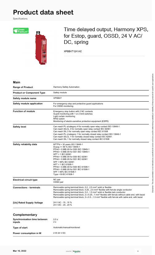
Product data sheetSpecificationsTime delayed output, Harmony XPS,for Estop, guard, OSSD, 24 V AC/DC, springXPSBAT12A1ACMainRange of ProductHarmony Safety Automation Product or Component Type Safety module Safety module name XPSBATSafety module application For emergency stop and protective guard applications For OSSD monitoringFunction of moduleEmergency stop button with 2 NC contacts Guard monitoring with 1 or 2 limit switches Light curtain monitoring RFID switchMonitoring of electro-sensitive protection equipment (ESPE)Safety levelCan reach PL e/category 4 for normally open relay contact ISO 13849-1Can reach SILCL 3 for normally open relay contact IEC 62061Can reach SIL 3 for normally open relay contact IEC 61508Can reach PL c/category 1 for normally closed relay contact ISO 13849-1Can reach SILCL 1 for normally closed relay contact IEC 62061Can reach SIL 1 for normally closed relay contact IEC 61508Safety reliability dataMTTFd > 30 years ISO 13849-1Dcavg >= 99 % ISO 13849-1PFHd = 0.98E-09 for SS0 ISO 13849-1PFHd = 0.96E-09 for SS1 ISO 13849-1HFT = 1 IEC 62061PFHd = 0.98E-09 for SS0 IEC 62061PFHd = 0.96E-09 for SS1 IEC 62061SFF > 99% IEC 62061HFT = 1 IEC 61508-1PFHd = 0.98E-09 for SS0 IEC 61508-1PFHd = 0.96E-09 for SS1 IEC 61508-1SFF > 99% IEC 61508-1Type = B IEC 61508-1Electrical circuit type NC pair OSSD pairConnections - terminalsRemovable spring terminal block, 0.2...2.5 mm² solid or flexibleRemovable spring terminal block, 0.25...2.5 mm² flexible with ferrule single conductor Removable spring terminal block, 0.2...1.5 mm² solid or flexible twin conductorRemovable spring terminal block, 2 x 0.25...1 mm² flexible with ferrule without cable end, with bezel Removable spring terminal block, 2 x 0.5...1.5 mm² flexible with ferrule with cable end, with bezel [Us] Rated Supply Voltage24 V AC - 15...10 %24 V DC - 20...20 %ComplementarySynchronisation time between inputs 0.5 s 2 sType of startAutomatic/manual/monitored Power consumption in W2 W 24 V DCD i s c l a i m e r : T h i s d o c u m e n t a t i o n i s n o t i n t e n d e d a s a s u b s t i t u t e f o r a n d i s n o t t o b e u s e d f o r d e t e r m i n i n g s u i t a b i l i t y o r r e l i a b i l i t y o f t h e s e p r o d u c t s f o r s p e c i f i c u s e r a p p l i c a t i o n sPower consumption in VA5 VA 24 V AC 50/60 HzInput protection type Internal, electronicSafety outputs 2 NO1 NOSafety inputs2Maximum wire resistance500 OhmTime delay range0...900 sInput compatibility Normally closed circuit ISO 14119Mechanical contact ISO 14119OSSD pair IEC 61496-1-2Normally closed circuit ISO 138503-wire proximity sensors PNP[Ie] rated operational current5 A AC-13 A AC-155 A DC-13 A DC-13Control outputs 3 pulsed outputInput/Output type Semiconductor output Z1, 20 mA[Ith] conventional free air12 Athermal currentAssociated fuse rating6 A gG NO relay output circuit IEC 60947-1 Minimum output current20 mA relay outputMinimum output voltage24 V relay outputMaximum response time on20 msinput open[Ui] rated insulation voltage250 V 2)EN/IEC 60947-1[Uimp] rated impulse withstand4 kV II EN/IEC 60947-1voltageLocal signalling LED green power power ONLED red error errorLED yellow state 1 safety output instantaneousLED yellow state 2 safety output delayedLED yellow start 1 startLED yellow start 2 startLED yellow S12 safety input S12LED yellow S22 safety input S22Mounting Support35 mm symmetrical DIN railDepth 4.72 in (120 mm)Height 3.94 in (100 mm)Width 1.77 in (45 mm)Net Weight0.77 lb(US) (0.350 kg)EnvironmentStandards IEC 60947-5-1IEC 61508-1 functional safety standardIEC 61508-2 functional safety standardIEC 61508-3 functional safety standardIEC 61508-4 functional safety standardIEC 61508-5 functional safety standardIEC 61508-6 functional safety standardIEC 61508-7 functional safety standardISO 13849-1 functional safety standardIEC 62061 functional safety standardProduct certifications TÜVcULusIP degree of protection IP20 terminals)EN/IEC 60529IP40 housing)EN/IEC 60529IP54 mounting area)EN/IEC 60529 Ambient air temperature for-13…131 °F (-25…55 °C)operationAmbient Air Temperature for-13…185 °F (-25…85 °C)StorageRelative Humidity5…95 % non-condensingOrdering and shipping detailsCategory22477-SAFETY MODULES (PREVENTA)Discount Schedule SAF2GTIN3606482034037Nbr. of units in pkg.1Package weight(Lbs)10.65 oz (302 g)Returnability NoPacking UnitsUnit Type of Package 1PCEPackage 1 Height 2.52 in (6.4 cm)Package 1 width 5.24 in (13.3 cm)Package 1 Length 6.02 in (15.3 cm)Unit Type of Package 2S03Number of Units in Package 216Package 2 Weight11.92 lb(US) (5.409 kg)Package 2 Height11.81 in (30 cm)Package 2 width11.81 in (30 cm)Package 2 Length15.75 in (40 cm)Package 3 Height11.81 in (30 cm)Offer SustainabilitySustainable offer status Green Premium productCalifornia proposition 65WARNING: This product can expose you to chemicals including: Lead and lead compounds, which isknown to the State of California to cause cancer and birth defects or other reproductive harm. For moreinformation go to REACh Regulation REACh DeclarationEU RoHS Directive Pro-active compliance (Product out of EU RoHS legal scope)EU RoHS DeclarationMercury free YesRoHS exemption information YesChina RoHS Regulation China RoHS declarationEnvironmental Disclosure Product Environmental ProfileCircularity Profile End of Life InformationWEEE The product must be disposed on European Union markets following specific waste collection andnever end up in rubbish bins.Dimensions Drawings DimensionsFront and Side Views(A) : Product drawing(B) : Spring terminal(C) : Side view(1) : Removable terminal blocks, top(2) : Removable terminal blocks, bottom(3) : LED indicators(4) : Delay factor selector(5) : Delay base selector(6) : Sealable transparent coverMounting to DIN railScrew-mountingConnections and SchemaWiring Diagram(1) : A1-A2 (Power supply)(2) : S11–S21 (Control outputs (DC+) of safety-related inputs), S12-S22 (Input channels (CH+) of safety-related inputs)(3) : Y1 (Control output of Start/Restart input), Y2 (Input channel for automatic/manual start), Y3 (Input channel for monitored start with falling edge)13-14-23-24 : Terminals of the safety-related outputs (instantaneous)37-38 : Terminals of the safety-related outputs (delayed)Z1 : Solid state output, not safety-related。

Eaton 072907Eaton Moeller® series E-PKZ0 Insulated enclosure, E-PKZ0, H x W x D = 129 x 85 x 124 mm, flush-mounted, rotary handle, black/gray, IP55General specificationsEaton Moeller® series E-PKZ0 Accessory Insulated enclosure0729074015080729075124 mm 129 mm 85 mm 0.224 kgIEC/EN 60947-4-1 CSA Class No.: 3211-05 CSA-C22.2 No. 14 CECSA File No.: 165628 UL UL 508UL Category Control No.: NLRV UL File No.: E36332 CSAProduct NameCatalog Number EANProduct Length/Depth Product Height Product Width Product Weight Certifications0 AAccessoriesIs the panel builder's responsibility. The specifications for the switchgear must be observed.0 W0 WMeets the product standard's requirements.Is the panel builder's responsibility. The specifications for the switchgear must be observed.Does not apply, since the entire switchgear needs to be evaluated.Meets the product standard's requirements.Black-gray rotary knobPE(N) terminalNEMA 1NEMA 12IP55NEMA 3RMeets the product standard's requirements.Meets the product standard's requirements.Is the panel builder's responsibility.eaton-manual-motor-starters-mounting-e-pkz0-accessory-dimensions.eps eaton-manual-motor-starters-enclosure-e-pkz0-accessory-dimensions-002.epseaton-manual-motor-starters-enclosure-e-pkz0-accessory-dimensions-003.epseaton-manual-motor-starters-enclosure-e-pkz0-accessory-dimensions.eps eaton-manual-motor-starters-enclosure-e-pkz0-accessory-3d-drawing-003.epsDA-CE-ETN.E-PKZ0-GIL03402029ZDA-CD-e_pkz0_gDA-CS-e_pkz0_gRated operational current for specified heat dissipation (In) Product category10.11 Short-circuit ratingEquipment heat dissipation, current-dependent PvidHeat dissipation capacity Pdiss10.4 Clearances and creepage distances10.12 Electromagnetic compatibility10.2.5 Lifting10.2.3.1 Verification of thermal stability of enclosuresFitted with:Degree of protection (front side)10.2.3.2 Verification of resistance of insulating materials to normal heat10.2.3.3 Resist. of insul. mat. to abnormal heat/fire by internal elect. effects10.8 Connections for external conductors10.9.2 Power-frequency electric strength DibujoseCAD model Instrucciones de instalación mCAD modelIs the panel builder's responsibility.Degree of protectionIP55NEMA OtherAmbient operating temperature - max40 °C10.7 Internal electrical circuits and connectionsIs the panel builder's responsibility.10.10 Temperature riseThe panel builder is responsible for the temperature rise calculation. Eaton will provide heat dissipation data for the devices.Static heat dissipation, non-current-dependent Pvs0 W10.9.3 Impulse withstand voltageIs the panel builder's responsibility.Enclosure materialPlasticAmbient operating temperature - min-25 °C10.2.2 Corrosion resistanceMeets the product standard's requirements.10.6 Incorporation of switching devices and componentsDoes not apply, since the entire switchgear needs to be evaluated.10.2.4 Resistance to ultra-violet (UV) radiationPlease enquire10.2.7 InscriptionsMeets the product standard's requirements.10.5 Protection against electric shockDoes not apply, since the entire switchgear needs to be evaluated.ModelBuilt-in10.13 Mechanical functionThe device meets the requirements, provided the information in the instruction leaflet (IL) is observed.10.2.6 Mechanical impactDoes not apply, since the entire switchgear needs to beEaton Corporation plc Eaton House30 Pembroke Road Dublin 4, Ireland © 2023 Eaton. Todos los derechos reservados. Eaton is a registered trademark.All other trademarks areproperty of their respectiveowners./socialmediaevaluated.Is the panel builder's responsibility.Does not apply, since the entire switchgear needs to be evaluated.0 W10.9.4 Testing of enclosures made of insulating material 10.3 Degree of protection of assembliesHeat dissipation per pole, current-dependent Pvid。


Supertex inc.HV9930DB1General DescriptionThe HV9930DB1 is an LED driver demoboard capable of driving up to 7 1-watt LEDs in series from an automotive input of 9 - 16VDC. The demoboard uses Supertex’s HV9930 in a boost-buck topology. The converter operates at frequencies in excess of 300kHz and has excellent output current regulation over the input voltage range. It can also withstand transients up to 42V and operate down to 6V input. The converter is also protected against open LED and output short circuit conditions. Protection against reverse polarity up to 20V is also included.Board Layout and Connection DiagramHigh Bright LED Driver IC DemoboardMeeting Automotive RequirementsConnections:Input - The input is connected between the terminals of connector J1 as shown in the Connection Diagram.Output - The output is connected between the terminals of connector J2 as shown.Enable/PWM Dimming:To just enable the board, short pins 1 and 2 of connector J3 as shown. For PWM dimming, connect the external push-pullsquare wave source between terminals 1 and 3 of connectorJ3 as shown by the dotted lines.Note: During PWM dimming, pin 2 of connector J3 should be left open. Also, the PWM signal must have the proper polarity with the positive connected to pin 1 of J3. Note that pin 3 of J3 is internally connected to the return path of the input voltage.Actual Size: 2.25” x 1.25”PWM DimmingV INTesting the Demo BoardNormal Operation: Connect the input source and the output LEDs as shown in the Connection Diagram and enable the board. The LEDs will glow with a steady intensity. Connect-ing an ammeter in series with the LEDs will allow measure-ment of the LED current. The current will be 350mA +/- 5%.Open LED test: Connect a voltmeter across the output ter-minals of the HV9930DB1. Start the demoboard normally, and once the LED current reaches steady state, unplug one end of the LED string from the demoboard. The output volt-age will rise to about 33V and stabilize.Short Circuit Test: When the HV9930DB1 is operating in steady state, connect a jumper across the terminals of the LED string. Notice that the switching frequency drops, but the average output current remains the same.PWM Dimming: With the input voltage to the board discon-nected, apply a TTL compatible, push-pull square wave sig-nal between PWMD and GND terminals of connector J3 as shown in the Connection Diagram. Turn the input voltage back on and adjust the duty cycle and / or frequency of the PWM dimming signal. The output current will track the PWMdimming signal. Note that although the converter operates perfectly well at 1.0kHz PWM dimming frequency, the best PWM dimming ratios can be obtained at lower frequencieslike 100 or 200HzTypical ResultsFig. 1 shows the efficiency plot f or the HV9930DB1 over the input voltage range. The converter has efficiencies greater than 80% over 13V input. Note that these measurements do not include the 0.3 - 0.5W loss in the reverse blocking diode.Fig. 2 shows the variation of the switching frequency over the input votage range. The frequency varies from 300kHz to 500kHz over the entire input voltage range and avoids the restricted frequency band of 150kHz to 300kHz and the AM band greater than 530kHz. This makes it easier to meet the conducted and radiated EMI specifications for the automo -tive industry.Fig.3 shows the output current variation over the input volt-age range. The LED current has a variation of about 2.0mA over the entire voltage range.7072747678808284Input Voltage (V)E f f i c i e n c y (%)300350400450500Input Voltage (V)S w i t c h i n g F r e q u e n c y (k H z )348.0348.5349.0349.5350.0350.5Input Voltage (V)O u t p u t C u r r e n t (m A )Fig. 3 Output Current vs. Input VoltageThe waveforms in Fig.4 show the drain voltage of the FET (channel 1 (blue); 10V/div) and the LED current (channel 4 (green); 100mA/div) at three different operating conditions – 9.0V in, 13.5V in and 16V in.Fig. 5 shows the operation of the converter during cold crank conditions as the input voltage decreases from 13.5V to 6V and increases back to 13.5V. In these cases, the input current reaches the limit set and the output current drops correspondingly. Thus, the LEDs continue to glow, but with reduced intensity. Once the voltage ramps back up, the out-put current goes back to its normal value and the converter comes out of the input current limit.Fig.6 shows the LED current during an input step change from 13.5 to 42V and back to 13.5V (similar to a clamped load dump). It can be seen that the LED current drops brieflywhen the input voltage jumps, but there are no overshoots.(a)(b)(c)Fig. 4. Steady State Waveforms(a): 9.0V in; (b): 13.5V in; (c): 16V inFig. 5. Cold Crank OperationChannel 1 (blue): Input voltage (10V/div)Channel 3 (pink): Input current (1A/div)Channel 4 (green): LED current; 100mA/divFig. 6 LED current during step changesin the input voltageChannel 1(blue): Input voltage (10V/div)Channel 4 (green): LED current (100mA/div)Fig. 7a shows the operation of the converter during an Open LED condition and Fig. 7b shows the operation during output short circuit condition. In both cases, it can be seen that the HV9930DB1 can easily withstand faults and come back into normal operation almost instantly.Fig. 8 shows the PWM dimming performance of the HV9930DB1 with a 100Hz, 3.3V square wave signal. The converter can easily operate at PWM dimming duty cyclesfrom 1% - 99%.(a): Open LED Condition(b): Output Short CircuitFig. 7 HV9930DB1 during output fault conditionsFET drain voltage (20V/div)Channel 1 in (a); Channel 2 in (b)Channel 4 (green): LED currentShort Circuit(a)(b)(c)Fig. 8 PWM Dimming at 100HzChannel 1 (blue): PWM Dimming Input Signal (2V/div)Channel 4 (Green): LED current (100mA/div)Fig. 9 shows the rise and fall times of the output current dur-ing PWM dimming. The converter has nearly symmetric rise and fall times of about 25µs. These rise and fall times can be reduced (if desired) by reducing the output capacitance C10. However, this will lead to increased ripple in the output current.Conducted EMI Tests on theHV9930DB1In preliminary tests conducted on the demo board, the board meets SAE J1113 Class 3 conducted EMI standards without the need for any input filters (other than the input capacitors already included). This is a result of the combination of the continuous input current and a localized switching loop (Q1 – C1 – D3).Table 1 details the conducted EMI limit as per SAE J1113 and the maximum conducted EMI obtained from measure-ments on the board. The table also lists the Class of the SAE standard the board meets in each frequency range.The conducted EMI plots for the HV9930DB1 obtained at an input voltage of 13.5V and an LED string voltage of 27V(output current is 350mA) are given in the Appendix. Fig. 9. PWM Dimming rise and fall timesChannel 1 (blue): PWM Dimming Input Signal (2V/div)Channel 4 (Green): LED current (100mA/div)(a): rise time(b): fall timeHV9930DB1 Circuit Schematic:PCB Top LayerPCB Bottom LayerAppendix – Conducted EMI Test ResultsAppendix – Conducted EMI Test Results (cont.)Ref. Level = 65dBµVRef. Level = 49dBµVSupertex inc. does not recommend the use of its products in life support applications, and will not knowingly sell them for use in such applications unless it receives an adequate “product liability indemnification insurance agreement.” Supertex inc. does not assume responsibility for use of devices described, and limits its liability to the replacement of the devices determined defective due to workmanship. No responsibility is assumed for possible omissions and inaccuracies. Circuitry and specifications are subject to change without notice. For the latest product specifications refer to the Supertex inc. (website: http//)©2013 Supertex inc.All rights reserved. Unauthorized use or reproduction is prohibited.Supertex inc.。

GEUSER MANUAL Uninterruptible Power Supply Line-interactive VCL Series UPS 400 – 600 – 800 – 1000 – 1500 VAGE Consumer & Industrial SAGeneral Electric CompanyCH – 6595 Riazzino (Locarno)SwitzerlandT +41 (0)91 / 850 51 51F +41 (0)91 / 850 52 52g imagination at workUser manualUninterruptible Power SupplyLine-interactive VCL Series UPS400 - 600 - 800 – 1000 - 1500 VAPlease read these instructions carefully before installation and start-up of the VCL Series UPS. Keep this manual in a safe place for future reference.Model: VCL Series 400 – 1500 VAIssued by: Product Document Department – Riazzino - CHDate of issue: 01.07.2013File name: OPM_VCL_XXX_0K4_1K5_XGB_V012Revision: 1.2Identification No.:Table of contents Page 1IMPORTANT SAFETY INSTRUCTIONS (4)1.1SAVE THESE INSTRUCTIONS (4)1.2SAFETY RULES (4)1.3WARRANTY (5)1.4STORAGE (5)2INSTALLATION & OPERATION (5)2.1INTRODUCTION (5)2.2INSTALLATION (6)2.3OPERATION (6)2.4BATTERY REPLACEMENT PROCEDURE (8)2.5RECYCLING THE UPS AT THE END OF SERVICE LIFE (9)3TROUBLESHOOTING (9)4SPECIFICATIONS (10)1 IMPORTANT SAFETY INSTRUCTIONS1.1 SAVE THESE INSTRUCTIONSThis manual contains important instructions that should be followed during installation and maintenance of the UPS. It also gives all necessary information about the correct use of the UPS.Before attempting to install and start up the UPS, carefully read this manual. Keep this manual next to the unit for future references.GE refuses any responsibility in case of non-observance, unauthorized alterations or improper use of the delivered UPS.The instructions in this manual are for UPS models VCL400, VCL600, VCL800, VCL1000 and VCL1500. You can find the model name at the rear panel of your UPS.While every care has been taken to ensure the completeness and accuracy of this manual, GE accepts no responsibility or liability for any loss or damage resulting from the use of the information contained in this document.1.2 SAFETY RULESThe UPS is intended to be used in normal domestic and office situations. The branch circuit supply has to be protected with a 16 A building fuse.The UPS must be powered from a single phase grounded wall outlet. This wall outlet must be easily accessible and close to the UPS. Do not use extension cords.Place cables in such a way that no one can step on or trip over them.Avoid locations that are excessively humid, near water, near heat sources or in direct sunlight.The ambient temperature should not exceed 40C. Optimal battery lifetime is obtained if the ambient temperature does not exceed 30C.It is important that ventilation air can move freely around and through the unit. Do not block the air vents.Do not plug appliances such as electric heaters, toasters and vacuum cleaners into the UPS. The UPS output can be used only for electronic loads such as computers and telecommunications equipment. Always disconnect the input power cord from the wall outlet before replacing the battery. Never dispose of batteries in a fire: they may explode.Never disassemble or reassemble batteries; their contents (electrolyte) may be extremely toxic.Never short the battery terminals. Shorting may cause the battery to burn. When working with batteries remove watches, rings or other metal objects and only use insulated tools.Proper disposal of batteries is required: refer to your local codes for disposal requirements.1.3 WARRANTYGE, operating through its authorized agents, warrants that the standard products will be free of defects in materials and workmanship for a period as per contract specifications.1.4 STORAGEStore the UPS in a dry location with the batteries in a fully charged state. Storage temperature must be within -15 +55C. If the unit is stored for a period exceeding 3 months, optimal battery lifetime is obtained if the storage temperature does not exceed 25°C.If the unit is stored for an extended period of time, the batteries must be recharged every 2 months.2 INSTALLATION & OPERATION2.1 INTRODUCTIONThe GE (General Electric) VCL Series UPS , a line-interactive uninterruptible power supply, has been designed to protect your sensitive electronic equipment such as computers and telecommunications equipment from virtually all forms of power interference, including complete power failures.When the mains supply is present and the UPS is switched on, the UPS is charging the battery and providing power to the connected equipment from the AC line directly. In case of a mains failure the reliable battery can provide the stable power to complete your work, save the data and safely shut down your system.Inspect the UPS for damage after unpacking. If any damage is present please immediately notify the carrier and place of purchase.Condensation may occur if the UPS system is moved directly from a cold to a warm environment. The UPS system must be absolutely dry before being installed. Please allow an acclimatization time of at least two hours prior to installation. Save the original packing material. No liability can be accepted for any transport damage when the equipment is shipped in non-original packaging.2.2INSTALLATION1. Connect the mains cord of the UPS to a working, grounded AC wall socket outlet. The unit will start automatically.2. For best results, allow the UPS to recharge the batteries during a period of approx. 8 hours. It is acceptable to usethe UPS without first charging the battery, but the runtime may be reduced.3. Plug your computer and monitor into the “Battery backup & surge protection” outlets. These outlets will provideemergency battery backup power during a mains power failure as well as surge protection from surges andspikes.CAUTION:Do NOT plug LASER PRINTERS into any of the “Battery backup &surge protection” or “surge protection”outlets.CAUTION:Do NOT plug an ACCESSORY SURGE strip into any of the “Battery backup & surge protection” outlets. 4. Plug your peripheral equipment (printer, scanner, fax, speaker, etc.) into the “Surge protection” outlets.NOTE: These outlets will NOT provide battery backup power during a mains power failure.5. When the “On mains” LED illuminates, switch on the connected equipment.2.3OPERATION1. ON/OFF ButtonPress and hold the ON/OFF button for one beep, then release it to turn on (or turn off) the UPS. The UPS will charge the battery as long as the mains power is present.NOTE: When you turn on the UPS it will perform a self-test during which the alarm will sound intermittently.2. LED On mains/ on battery (green)This green LED illuminates when the UPS is on and receiving the normal mains power. It indicates that theconnected equipment is receiving power and the battery is charging.The LED will blink and the alarm beeps every 10 seconds when the UPS operates on battery.3. LED Overload/ replace battery/ UPS fault (red)This red LED will blink and the alarm sounds 2 beeps every second when the load connected to the “Batterybackup & surge protection” outlets exceeds the nominal capacity of the UPS. The UPS will automatically shut down after beeping for ten seconds.The LED will blink and the alarm sounds 3 beeps every 30 seconds when the UPS detects that the battery needs to be replaced soon. Allow the UPS to recharge the battery for at least 4 hours. If the LED lights again after 4 hours of charging, the battery needs to be replaced to ensure full protection for your equipment. Contact your dealer.When the UPS detects a hardware fault, the red LED will illuminate, the alarm will sound continuously and the UPS will shut down. In some instances the fault condition may be cleared by switching the UPS off and then on again.4. Input socketAC mains supply to the UPS.5. Outlets “Surge protection”The outlets provide full time protection from surges and spikes. Peripheral equipment that does not require power during a mains power failure, e.g. printers, scanners, fax machines, or speakers can be connected to these outlets.6. Outlets “Battery backup & surge protection”The outlets not only provide full time surge protection but also provide emergency battery backup power during a mains power failure such as a blackout or brownout.7. Phone/FAX protectionThe RJ11 jacks can provide protection against surges and spikes on your phone line.8. RJ11 USB communication portThe provided GE monitoring and shutdown software can be automatically configured to save your files and shut down your computer in the event of a prolonged power outage. Refer to the manual that came with the software.9. Circuit breakerIn case of a severe overload the circuit breaker may trip. The button will come out, the UPS is disconnected from the mains and output power is lost. In this situation reduce the load connected to the “Battery b ackup & surge protection” and/or “Surge protection” outlets of the UPS. Subsequently reset the circuit breaker by pushing the button back in.LED display & buzzer alarm list2.4BATTERY REPLACEMENT PROCEDURE(Qualified service personnel only)1. Turn off the equipment that is connected to the output sockets of the UPS.2. Turn off the UPS.3. Unplug the UPS power cord from the AC wall outlet.4. Unplug the equipment from the output sockets of the UPS.5. Remove the 2 screws at the bottom side of the front panel (fig. 1.)6. Slide the panel downward, off the UPS (fig. 2).7. Disconnect the red and black DC wires from the battery terminals (fig. 3).NOTE : DO NOT short the battery wires.8. Replace the battery.9. Connect the battery wires to the battery terminals.NOTE: a small spark might occur, this is normal.10. Reinstall the front panel (fig. 4).11. Fasten the two screws (fig. 5).General guidelines1. When replacing the batteries, use only the same type and size battery.2. Never short the battery terminals. Shorting may cause the battery to burn. When working with batteries removewatches, rings or other metal objects and only use insulated tools.3. Avoid charging in a sealed container.4. Never dispose of batteries in a fire: they may explode.5. Never disassemble or reassemble batteries; their contents (electrolyte) may be extremely toxic. If exposed toelectrolyte, wash immediately with plenty of water, if eye contact occurs flush with water and contact a physician.2.5 RECYCLING THE UPS AT THE END OF SERVICE LIFE3 TROUBLESHOOTINGWhenever a malfunction occurs, first check external factors (e.g. connections, temperature, humidity or load) to determine whether the problem is caused by the unit itself or by its environment. Subsequently check the thermal circuit breaker: it may be tripped. If so: reset it and be sure that the UPS is not overloaded.The following chart is a simple troubleshooting checklist only. If the suggested solution does not succeed, or if the information is insufficient to solve the problem, please contact your dealer or consult .PB4SPECIFICATIONSModel : VCL400 VCL600 VCL800 VCL1000 VCL1500Rating VA/W : 400/250 600/360 800/480 1000/600 1500/900AC input voltage window : 170 ~ 280VacFrequency : 50 / 60 Hz auto sensingBattery type : 12V, sealed lead acid, maintenance freeNumber x capacity of battery : 1x4.5Ah 1x7Ah 1x9Ah 2x7Ah 2x9AhBattery recharge time : 8 hours typicalRuntime in minutes at typical load (60%) : 5 6 6 8 6Internet / phone / fax protection : RJ-11 (One pair), 2C; 114 joules; clamping rate 330VCommunication port : USB (RJ11)Ambient temperature : 0°C ~ 40°C (+32°F ~ 104°F)Maximum relative humidity : 95% (non-condensing)Storage temperature : -15°C ~55°C (+5°F ~ 131°F)Net weight (kg) : 4.0 4.6 5.6 8.4 10.3Dimensions (hxwxd, mm) : 220x112x222 220x112x330This document shall not be copied nor reproduced without the permission of GE.Due to technical improvements, some of the information contained in this manual may be changed without notice.© General Electric Consumer & Industrial SA. All rights reserved; reproduction without permission prohibited. The content of this manual may be subject to change without prior notice; no liability can be accepted for any error or omission. The illustrations and plans describing the equipment are intended as general reference only and are not necessarily complete in every detail.。

2020-07-29v2.60~37 beta version – condensed change log – release date to be determinedNote that v2.60 is still in beta.Details here: https:///live/ccgx:beta-testingThis document contains all differences compared to the last official version (v2.57). Compared to the regular updates on Community, this takes away all intermediate changes and fixes.Change log:Product support:•Add Inverter RS (possibly there are some limitations, monitoring when connected through VE.Direct works. Remote firmware updating & connecting through VE.Can is still being looked into.•Phoenix Inverters VE.Directo Fix how systems these inverters are visualised in the GUI on the overview, as well as on the detailed menus.o Use the best available power reading: first generation Phoenix VE.Direct inverters. Newer models have a better current & power measurement – which now also the GX device showswhen available.•VE.Bus Inverters:o Hide non-relevant items from the detailed menus•Phoenix Smart Charger IP43: Fix voltage and current not properly shown for output 1. This bug was introduced in v2.30•Inverter/chargers:o Add option to name the inverter/charger (see the Device submenu, its at the bottom of the inverter/charger menu)o Fix kWh reading errors on all Multi Compacts as well as the newer MultiPlus500/800/1200/1600 when on firmware version 467 or newer. Issues with kWh readings aremost noticeably visible on the VRM Portal graphs.•For all products that didn’t have the option yet, make it possible to set a custom name. This includes tanks as well as Solar Chargers connected in a VE.Can network, and more.•Add support for the new GX LTE 4G.Marine MFD integration via App:•Various layout improvements, including using pagination rather than hiding metrics when there is too much to show for the used screen size.•Add Generator on/off control (for generators controlled with start/stop wired to the relay on the GX device)•Fix the Victron App icon blinking on Navico displays.•Add support for Fischer Panda Generators. They are now shown on the page, including details (XYZ) as well the option for the user to switch between Off, On and Auto.•Stability improvements such as automatically reconnect to MQTT in case the connection was lost due, for example, a power cycle of the GX device or loss of network.NMEA2000-out feature:•Add Solar Chargers: now, solar charger data, including PV Array Voltage & Current, is available as standard N2K PGNs.•Add Tank levels, including automatically numbered default data instances. Those defaults are the same as the NMEA2000 Device Instance, instance 0 is assigned to the first tank, instance 1 isassigned to the second tank, and so forth.•Add a page to configure the VE.Can & N2K Device instance. Its available under the Settings -> Services -> VE.Can menus.•Add reading of GPS location from a NMEA2000 connected GPS. This changes Venus OS from handling only one GPS to (potentially) reading data from multiple GPS-es. All available (USB & NMEA2000)GPS-es are visible in the "Settings -> GPS" menu. And for the location as sent to VRM, as well as the icons in the GUI, it picks one with a valid position fix.•Improve the menus by changing wording and making the more intuitive to use.ESS:•Add installer configurable Feed-in limit setting (Power / Watts). It works both for AC-Coupled PV (Fronius & ABB) and DC-Coupled PV as well as a combination of both. For limiting feed-in of DC-Coupled PV, VE.Bus firmware 469 is required.•Add a new Energy Meter, the Carlo Gavazzi EM24 three-phase ethernet model. Also stocked by us, part number REL200200100. Carlo Gavazzi part number EM24-DIN.AV2.3.X.E1.X. Compared to theexisting energy meters, which are connected over RS485, this meter offers the advantage that byusing the Ethernet (or WiFi when adding bridges) network can be used – no need to pull RS485 wiring between the distribution board and the battery system. More information in the manual (TODO ADDMANUAL & LINK & ADD OR UPDATE PRODUCT PAGE ON WEBSITE)•Fix issue in scheduled charging, that made it impossible to set it above 23:00 hours on a few time zones.•Change how the “Grid meter installed yes/no” setting works. Now there is a setting called “Grid metering”; with two options: External meter and Inverter/charger.•Clean up the ESS configuration menus. Menu entries are better worded, ánd they are now better organised.•Improve the PV-limiting (aka zero feed-in) feature for large installations; sometimes they limited too much.•Better handle a DCL=0 limit from managed batteries by completely stopping discharge by the inverter/charger. Previously the system would try to still use power available from PV. Better to firstuse that to charge the battery, which will automatically make the managed battery to lift the DCL=0 restraint once sufficiently charged.PV Inverter monitoring:•Improve how the scanning mechanism works. For all types, and especially for Fronius PV Inverters •Fix a bug in relation to Fronius PV Inverters was fixed that caused the system to read 0W output now and then, while the actual power was higher. This issue caused downward spikes in graphs on VRM,but could also affect the Fronius Zero feed-in functionality: all works better now.•Add option to remove previously detected IP Addresses.•Significantly reduce the scan time. It was accidentally increased a lot when adding the Ethernet link-local addressing in v2.30.•Various other stability & performance improvements.Tank level monitoring (applies to analog inputs on Venus GX & Cerbo GX)•Add option to name tanks•Add option to configure a custom minimum and maximum resistance level•Add option to configure a custom shape: up to ten points can be configured, and the tank level is linearly interpolated between the points.•Fix bug that the read-out value didn’t always immediately read the correct level; at some tank levels it could take a long time for the right value to come through the filtering at start-up. Not any-more.•Add “Sensor resistance” to the menu. This is a read-out of raw & unfiltered resistance measurement, to aide in troubleshooting.Other changes:•Generator start/stop: improve how it gets the battery monitor data; details here.•Increase the speed of Remote VEConfigure by a factor 2 or 3•Move the VRM Two-way communication menu to the VRM Portal menu•Remote Console on LAN: fix mIncrease the sharpness of Remote Console on LAN•Improve resolution of several icons on higher resolution devices, such as the Cerbo GX by using better SVGs•Change the name of the CAN-bus services in the Settings -> Services menu. Now the used naming matches the labelling on the physical products.•Hide the Battery Details menu for battery (monitor) types that do no support that data.•Fix Error #48 showing in demo mode•Show the link-local IP Address in the Ethernet menu. To help when diagnosing Ethernet network issues as well as make it less hidden that the GX devices have a link-local address.•Improve WiFi stability: in some rare cases it would not retry to connect after losing a connection. Now it will always reconnect, instead of timing out, or limiting attempts, or giving up on other errors.•Disallow accidentally booting into an incompletely installed firmware update (this was -sometimes- possible by using the backup firmware menu. Not any more)•Send ARP replies the from correct network interface.This will not affect any normal installations; but was still wrong. Details here: https:///questions/49662/ccgx-ethernet-mac-address-changing-link-local.html. Thank you Kenrick for highlighting this.•In all Device submenus, rename Device instance to VRM instance. To make it cleared that its not the same as the VE.Can instance / NMEA2000 device instance.•GX GSM: Increase the max length of APN that can be entered•Grid failure alarm: fix issue where it could generate alarm in case left disabled while not having any inputs configured as Grid or Shore. In which case the setting itself is hidden, making the alarms rather mysterious aka unexpected. Not anymore: it will not generator alarms when there are no AC Inputsconfigured to be Grid or Shore.DVCC & Managed batteries:•Freedomwon batteries: force enable DVCC, and SVS & STS off, similar to other managed batteries.•Freedomwon batteries: show Freedwon logo on the GUI overview page•Pylontech: increase the charged battery voltage from 52 to 52.4. This fixes the issue that some batteries would always linger 98 or 99% rather than their SOC showing 100%.•Fix issue in which the GX Device applied current control to solar chargers configured to a VE.Can Device instance of 1 and higher; while as per documentation it should only control them whenconfigured with their VE.Can Device instance set to 0 (which is the default). The feature to have anoption to not control all solar chargers is for systems with multiple battery banks, such as a yacht.This is similar to synchronised parallel charging on VE.Can: also that works by VE.Can DeviceInstance.•Fix temperature source selection. The names were so long that it was impossible to see which one you were selecting.ModbusTCP•Add various new registers, such as one for the new Grid feed-in limiter setting.•Change the grid failure alarm register. This was at register 830, unit id 0 & 100, and is now at register64 on the vebus unit id. See the Unit ID mapping tab in the ModbusTCP spreadsheet. This is abreaking change that requires customers that use this register to update their ModbusTCPconfiguration, we know that is not good, and don't like it ourselves - but saw no sensible othersolution.。


—DATA S H EE TPower supply CP-E 24/0.75Primary switch mode power supplyThe CP-E range offers enhanced functionality while the number of different types has been considerably reduced. Now all power supply units can be operated at an ambient temperature of up to +70 °C.Characteristics• Rated output voltage 24 V DC• Output voltage adjustable via front-face rotary potentiometer “OUTPUT Adjust”• Rated output current 0.75 A • Rated output power 18 W• Wide range input 100-240 V AC (90-264 V AC, 120-375 V DC)• Typical efficiency of 77 %• Low power dissipation and low heating• Free convection cooling (no forced cooling with ventilators)• Ambient temperature range during operation -20...+70 °C • Open-circuit, overload and short-circuit stable • Integrated input fuse• Redundancy unit CP-RUD offering true redundancy, available as accessory • LEDs for status indication—ApprovalsAUL 508, CAN/CSA C22.2 No. 107.1 1)H UL 1310, CAN/CSA C22.2 No. 223 (Class 2 Power Supply)H ANSI/ISA‑12.12, CAN/CSA C22.2 No. 213 (Class I, Div. 2, hazardous locations)HUL 60950, CAN/CSA C22.2 No. 60950 1)UL 62368‑1, CAN/CSA‑C22.2 No. 62368‑1R EAC ECCC 1)1) Approval refers to rated input voltage Uin— Marksa CE bRCM—Order dataType Input voltage range Rated output voltage / current Order codeCP‑E 24/0.7590‑264 V AC / 120‑375 V DC24 V DC / 0.75 A1SVR 427 030 R0000—Order data – accessoriesType DescriptionOrder codeCP-RUDRedundancy unitThe CP-RUD provides decoupling of two CP-E power supply units ≤ 35 V and < 5 A.1SVR 423 418 R90002C D C 271 017 F 0006OUTPUT L+, L–:INPUT L, N, PE:OUTPUT Adjust:Circuit diagramApplicationThe primary switch mode power supply offers two voltage input ranges. This enables the supply with AC or DC. Furthermore it is equipped with two generous capacitors, which ensure mains buffering of at least 75 ms (at 230 V AC). That is why the devices can be used worldwide also in high fluctuating networks and battery-powered plants.Operating modeBy means of the potentiometer “OUTPUT Adjust” the output voltage can be adjusted within a range of 21.6 to 28.8 V DC. Thus, the power supply can be optimally adapted to the application, e.g. compensating the voltage drop caused by a long line length.The green LED “OK” is lightening during proper operation.The red LED “LOW” is lightening when the output voltage is too low.MountingThe switch mode power supply can be snapped on a DIN rail according to IEC/EN 60715 as shown in the accompanying picture. For that the device is set with its mounting rail slide on the upper edge of the mounting rail and locked by lifting it downwards.2C D C 272057F 0b 06DemountingRemove the switch mode power supply as shown in the accompanying picture. For that the latching lever is pulleddownwards by means of the screwdriver. Alternatively you can press the unlock button to release the device. Then in both cases the device can be unhinged from the mounting rail edge and removed.2C D C 272058F 0b 06Mounting positionThe devices have to be mounted horizontally with the input terminals on the b ottom. In order to ensure a sufficient convection, the minimum distance to other modules should not be less than 25 mm in vertical and horizontal direction.2C D C 272059F 0b 062C D C 272 059 F 0b 06Connect the input terminals L and N. The protective earth conductor PE must be connected. The i nstallation must be executed acc. to EN 62368-1, provide a suitable disconnecting device (e. g. line p rotection switch) in the supply line. The input side is protected by an internal input fuse.Rate the lines for the maximum output current (considering the short-circuit current) or provide a s eparate fuse protection. We recommend to choose the cable section as large as possible in order to minimize voltage drops. Observe the polarity. The device is overload, short-circuit and open-circuit proof. The secondary side of the power supply unit is electrically isolated from the input and internally not earthed (SELV) and can therefore be earthed by the user according to the needs with L+ or L- (PELV).Connection diagramL-L+PE N LL-L+L N PEPWM2C D C 272054F 0b 06L+, L-Output voltage L, N Input voltage PEProtective earthIn operation pay attention to:• Do not modify the installation (primary and secondary side)! High current!Risk of electric arcs and electric shock (danger to life)!• Risk of burns: Depending on the operation conditions the housing can become hot.• The device contains no user serviceable parts. In any case of device malfunction please send the unit backto manufacturer.The device must be installed by qualified persons only and in accordance with the specific national regulations (e. g. VDE, etc.).The CP-E power supplies are chassis-mounted units. It is maintenance-free and does not contain any integral setting elements and should therefore not be opened.Before any installation, maintenance or modification work:• Read the operating and installation instructions carefully and completely!• Disconnect the system from the supply network and protect against switching on!CAUTIONImproper installation/operation may impair safety of personnel and cause operational difficulties or destruc -tion of the unit.WARNINGBefore start of operation the following must be ensured:• Connection to mains or DC supply according to the specific national regulations for class of protection I.Power supply cables and unit must be sufficiently fused. A disconnecting device has to be provided for the end product to disengage unit and supply cables from supply mains if required.• Rate the output lines for the output current of the power supply and connect them with the correctpolarity.• In order to ensure sufficient convection the distance to the other devices has to be considered.WARNINGDanger to life!Never carry out work when voltage is present. The power supply contains components with high stored energy and circuits with high voltage! Do not introduce any objects into the unit and do not open the unit. With some units of this range the output is capable of providing hazardous energy. Ensure that the service personnel is protected against inadvertent contact with parts carrying energy. If the internal fuse is blown most probablythe device is defect. In this case an examination of the device by the manufacturer is necessary.!!!Data at T a = 25 °C, U in = 230 V AC and rated values, unless otherwise indicated—Input circuitsSupply circuitsRated input voltage U in L,N100‑240 V ACInput voltage range AC90‑264 VDC120‑375 VFrequency range AC47‑63 HzTypical input current at 115 V AC335 mAat 230 V AC210 mATypical power consumption22.8 WInrush current limiting at 115 V AC15 Aat 230 V AC30 ADischarge current input / output0.25 mAinput / PE 3.5 mAPower failure buffering time at 115 V AC min. 20 msat 230 V AC min. 75 msInternal input fuse 2 A slow‑acting / 250 V ACPower factor correction (PFC)no—User interfaceIndication of operational statesOutput voltage OK: green LED V: output voltage OKLOW: red LED V: output voltage too low—Output circuitRated output voltage L+, L-24 V DCTolerance of the output voltage0 ... +1 %Adjustment range of the output voltage21.6‑28.8 V DCRated output power18 WRated output current I r T a≤ 60 °C0.75 ADerating of the output current60 °C < T a≤ 70 °C 2.5 %/°CMaximum deviation with load change statical±2 %change of output voltage within theinput voltage range±1 %Control time< 2 msStarting time after applying the supply voltageat I r max. 1 s with 7000 µF max. 1.5 sRise time at I r max. 150 mswith 7000 µF max. 500 msFall time max. 150 msResidual ripple and switching peaks BW = 20 MHz50 mVParallel connection yes, to enable redundancy Series connection yes, to increase voltage Resistance to reverse feed 1 s – max. 35 V DCCharacteristic curve of output Hiccup-modeShort‑circuit protection continuous short-circuit proofShort‑circuit behaviour Hiccup-modeOverload protection output power limitingNo-load protection continuous no-load stabilityStarting of capacitive loads7000 µF—General dataPower dissipation typ. 4.45 WEfficiency typ. 77 %Duty time100 %Dimensions (W x H x D)22.5 x 90 x 114 mm(0.89 x 3.54 x 4.49 in)Weight0.143 kg (0.315 lb)Material of housing PlasticMounting DIN rail (IEC/EN 60715), snap‑on mounting without any tool Mounting position horizontalMinimum distance to other units horizontal / vertical25 mm / 25 mm (0.98 in / 0.98 in)Degree of protection housing / terminals IP20 / IP20Protection class I—Electrical connection – input circuit / output circuit—Environmental dataAmbient temperature range operation‑20…+70 °C (‑4...+158 °F)rated load‑20...+60 °C (‑4...+140 °Fstorage‑25…+85 °C (‑13...+185 °F)Damp heat95 % RH, without condensationVibration (sinusoidal) (IEC/EN 60068‑2‑6)10‑500 Hz, 2 G, along X, Y, Z each axis, 60 min. for each axis Shock (half‑sine) (IEC/EN 60068‑2‑27)15 G, 11 ms, 3 axis, 6 faces, 3 times for each face—Isolation dataRated insulation voltage U i input / output 3 kV ACinput / PE 1.5 kV ACoutput / PE0.5 kV AC; 0.71 kV DCPollution degree2Overvoltage category II—Standards / DirectivesStandards IEC/EN 62368‑1Low Voltage Directive2014/35/EUProtective low voltage SELV (IEC 60950‑1)EMC Directive2014/30/EURoHS Directive2011/65/EUInterference immunity to IEC/EN 61000‑6‑2electrostatic discharge IEC/EN 61000‑4‑2Level 4 (air discharge 15 kV / contact discharge 8 kV)radiated, radio-frequency, electromagnetic fieldIEC/EN 61000‑4‑3Level 3 (10 V/m)electrical fast transient / burst IEC/EN 61000‑4‑4Level 4 (4 kV / 2.5 kHz)surgeIEC/EN 61000‑4‑5L‑L Level 3 (2 kV) / L‑PE Level 4 (4 kV)conducted disturbances, induced by radio-frequency fieldsIEC/EN 61000‑4‑6Level 3 (10 V)power frequency magnetic fields IEC/EN 61000‑4‑8Level 4 (30 A/m)voltage dips, short interruptions and voltage variations IEC/EN 61000‑4‑11dip: >95 % 10 ms / >30 % 500 ms interruptions: >95 % 5000 ms Interference emission IEC/EN 61000‑6‑3high-frequency radiated IEC/CISPR 22, EN 55022Class B high-frequency conductedIEC/CISPR 22, EN 55022Class B limits for harmonic current emissionsIEC/EN 61000‑3‑2Class D—Technical diagramsOutput behaviourThe switch mode power supply CP‑E 24/0.75 is able to supply at 24 V DC output voltage and • at an ambient temperature of:≤ 60 °C a continuous output current of approx. 0.75 A • at ambient temperatures of:60 °C < T a ≤ 70 °C the output power has to be reduced by 2.5 % per °C temperature increase.Temperature behaviourP T a [°C]2C D C 272016F 0211Characteristic curve of temperature at rated load2C D C 272022F 0011CP-E 5/3.0Dimensions accessoriesin mm [inches]2C D C 252188F 0b 05CP-RUD10DATA SHEET CP-E 24/0.75—Further documentationDocument title Document type Document number Electronic Products and Relays Technical catalogue2CDC 110 004 C02xx Power Supply Units Application manual2CDC 114 048 M020x Redundancy unit CP-RUD Data sheet2CDC 114 032 D0201You can find the documentation on the internet at /lowvoltage-> Automation, control and protection -> Power supplies.—CAD system filesYou can find the CAD files for CAD systems at http://abb‑control‑‑> Low Voltage Products & Systems ‑> Control Products ‑> Power Supplies.D ocum e n t n u m b e r 2C D C 114043D 0201 R e v . I (02/2021)—We reserve the right to make technical changes or modify the contents of this document without prior notice. With regard to purchase orders, the agreed particulars shall prevail. ABB Ltd. does not accept any responsibility whatsoever for potential errors or possible lack of information inthis document.We reserve all rights in this document and in the subject matter and illustrations contained therein. Any reproduction, disclosure to third parties or utilization of its contents – in whole or in parts – is forbidden without prior written consent of ABB Ltd. Copyright© 2021 ABB Ltd.All rights reserved /lowvoltage —ABB STOTZ-KONTAKT GmbH Eppelheimer Strasse 8269123 Heidelberg, Germany。

EV2456-WTYouradvantagesDer EIZO FlexScan EV2456erfüllt höchste Ansprüche an einen modernen Bildschirmarbeitsplatz.Bildqualität und Ergonomie überzeugen gleichermaßen.Mit 1920x 1200Bildpunkten,ei-nem IPS-LCD-Modul mit LEDBacklight und reflexionsarmer Ober-fläche meistert er eine detailreiche und exzellente Bildwieder-gabe.Das erleichtert die Arbeit im Büro.Für die blendfreie,klare Sicht auf das Bild sorgt Auto-EcoView und regelt die Helligkeit passend zur Umgebung.Insgesamt wirkt der UltraSlim-Monitor wegen seiner extrem schmalen Ränder sehr kompakt.Besonders im Mehrschirmbetrieb brilliert der fast rahmenlose Monitor mit überzeugender Übersicht.Die zum Lieferumfang gehörige Soft-ware Screen InStyle eröffnet die Möglichkeit,den Schirm vom Windows PC oder aus dem Netzwerk zu steuern.Mehrschirmlö-sungen lassen sich mit Screen InStyle synchron bedienen.24.1”LCD monitor with 16:10aspect ratio and IPS technology for outstanding image quality Bezel only 1mm on both sides and at the top:extre-mely compact and elegant design Contrast 1000:1,brightness 350cd/m ²,178°view-ing angle Flicker-free image reproduction thanks to hybrid brightness control Auto EcoView,EcoView Index,and EcoView Optimi-zer For maximum power savings and superb ergono-mics Integrated speakers and headphone jackUSB 3.0hub with one upstream and two downstream ports DisplayPort,HDMI,DVI-D,and D-Sub inputs for digital and analogueconnection24.1"Office-MonitorUltra-slim.Ultra-smooth!Whether it’s in sophisticated black or pristine,eye-grabbing white:The ultra-thin design with its bezel of only 1mm and its completely flat and smooth front side is truly impressive.A thin black glass frame with a width of just 5.2mm is all that separates the display and bezel from one another.Even from the thin side and smart-looking back,the monitor will make passers-by do a double take.The EV2456model also offers a fully flat front surface with integrated sensorbuttons.Maximum image quality thanks to the IPS panelThe monitor is capable of all three key elements of excellent image quality:excellent resolution of 1920x 1200pixels,maxi-mum contrast of 1000:1,and stable brightness of up to 350cd /m 2.That means you will experience razor-sharp text contours,brilliant graphics,and clear images.Thanks to the high-quality IPS panels with LED backlight,contrasts and colours remain sta-ble from every viewingangle.Precise colour controlAn image can only be perfect if the colours are,too.This is why EIZO office monitors have a 10-bit look-up table at a minimum,which allows the colour information to be assigned much more precisely than with conventional 8-bit LUTs.The finest colour gradations ensure that gradients are always perfectly displayed,while also offering customised adjustment options.For example,you can adjust the white balance from 4000K to 10000K in 500-Kintervals.Look-Up-Table with 10and morebit Look-Up-Table with 8bitSave electricity and your eyes with Auto EcoViewAt day,at night,bright,dark:No matter when and how you work,the Auto EcoView function continuously measures changes of the ambient light and optimises the monitor with ideal bright-ness values fully automatically by using a sensor.The benefits:Annoying glare is reduced,your eyes will not get tired as quickly.A special two-point control takes into account the brightest and darkest environment over the course of the day with the respec-tively desired screen brightness.Another advantage:Thanks to the automatic brightness adjustment,you will save up to 50%of your electricity costs in comparison to a monitor that is per-manently operated at maximum brightness.Of course,you can also continue to configure the monitor manu-ally.EcoView Index is used for orientation on how environmen-tally friendly and economical your settings are.Anti-glare coating:more image,less reflectionThe EV2456offers a surface with optimal anti-glare coating.By minimising glare from the spread of the reflected light,the anti-glare coating effectively protects your eyes from straining.This keeps your eyes from getting as tired and allows you to sit comfortably in front of the screen,without having to sit in a forced position to prevent glare.Flicker free:for the sake of the eyesTo help protect your eyes,EIZO has developed a hybrid tech-nology to control the backlight.This combines the benefits of the otherwise standard PWM (pulse width modulation)and DC (di-rect current)control.The PWM control uses much higher frequen-cies than standard PWM methods.The result:a flicker-free view-ing experience.Flickering is reduced down to absolute freedom from flickering,without impairing image quality or colour stabi-lity.In addition,the brightness can be set to less than 1%of the maximum value in darkly lit rooms.The benefit:Your screen re-mains free from glare even under theseconditions.Preset colour modes:Optimised display at the press of a buttonPreset colour modes make it easier for you to work and view images,texts and videos.This is because when choosing colour settings,it makes a difference whether you are looking at a film,editing an image,surfing the Internet or writing texts.You can configure the respective default settings for brightness,gamma correction and colour temperature at the press of a button.For example,paper mode simulates the pleasant contrast of books by reducing the blue light portion and brightness.This reduces wear on your eyes when reading documents and prevents tired-ness.Screen InStyleIn addition to the on-screen menu,you can conveniently con-trol the EV2456by using the Screen InStyle software on a Win-dows PC.The configuration options include colour reproduc-tion,energy saving options,and ergonomic functions that allow you to reduce the blue light portion (Circadian Dimming).The Screen InStyle software allows the user to apply the settings to all connected screens when using a multi-screen system.More about Screen InStyleScreen InStyle Server is a server application that allows system administrators to centrally manage and control monitors on which Screen InStyle is installed and which are connected to the network.This optimises power consumption and simplifies monitor asset management.More about Screen InStyle ServerMonitor Configurator for cross-network settings Reduced workload for network administrators:The software allows you to configure multiple monitors uniformly in a single step –via a USB connection.This saves you time and ensuresyou have the same settings on all screens.The configuration can be saved as an XML file and transferred toclients.Operation made easy thanks to the Button GuideThe Button Guide provides all functions at a glance.Touching the button is enough and the screen will show all functions and the corresponding controlpanel.Overdrive to quickly change imagesFast,faster,overdrive.The overdrive function accelerates swit-ching time so that the grey-grey change takes only 5ms on ave-rage.You can watch films and rapidly changing images without annoying afterglow.Save up to 30%of energy with the EcoView Optimizer Save electricity without compromising quality:The EcoView Optimizer reduces the background lighting fully automatically for dark images.This reduces electricity consumption by up to 30%.At the same time,the signal is amplified and the colour tone values adjusted.The result:You will enjoy the image quality you are used to but consume lesspower.LED backlight:Economical in consumption,free from mercury The monitors with an LED backlight help save the environment throughout their entire service life –from manufacturing through operation to disposal.For on the one hand they are characteri-zed by particularly low electricity consumption.The typical con-sumption is just 11Watt.On the other hand,they are free from mercury –a substance that is harmful to both humans and the en-vironment and is very difficult to disposeof.Zero-Watt consumption thanks to the power switch The monitors have an integrated mechanical power switch,which is extremely practical and energy-saving:If you switch off the monitor using the power switch,the device will stop consu-ming any power at all.Moreover,it consumes a maximum of 0.5watt in standby mode.One monitor,many portsIt doesn’t get easier than this:You can connect most of your devices,such as PC,laptop or cameras directly to the monitor because the monitor hasa number of different ports.That makes your daily work easier.Perfectly organizedThe monitor ships with a cable holder,which ensures a clean desk and prevents messycabling.Flexible baseErgonomic and stable:the adjustable stand focuses on ergono-mics.You can rotate,swivel and tilt the monitor stand until you find the most comfortable setting for your back,neck and sitting posture.It features continuous height adjustment and can be lo-wered almost to the base plate of the stand,enabling you to po-sition the top image line ergonomically right below your eye le-vel.Height 158.6mm TiltTilt down 5°,tilt up 35°Swivel 344°RotationRotation 90°(right andleft)Five-year warrantyEIZO grants a five-year warranty.This is possible thanks to the highly developed production process based on a simple princi-ple of success:sophisticated and innovative monitor technology,made from high-endmaterials.FeaturesGeneralItem no.EV2456-WTCase colors WhiteAreas of application OfficeProduct line FlexScanEAN4995047049739Variants EV2456-BK(Colour:Black)DisplayScreen size[in inches]24.1Screen size[in cm]61.1Format16:10Viewable image size(width x height)518x324Ideal and recommended resolution1920x1200Pixel pitch[mm]0.27x0.27Resolution supported1920x1200,1600x1200,1680x1050,1280x1024,1024x768,800x600,720x400,640x480 Panel technology IPSMax.viewing angle horizontal178°Max.viewing angle vertical178°Number of colours or greyscale16.7million colours(display port,8Bit),16.7millioncolours(HDMI,8Bit),16.7million colours(DVI,8Bit),16.7million colours(Dsub,8Bit)Colour palette/look-up table 1.06billion colour tones/10BitMax.colour space(typical)sRGBMax.brightness(typical)[in cd/m²]350Max.dark room contrast(typical)1000:1Typical response time[grey/greyalternation]5msMax.refresh rate[in hertz]60Backlight LEDFeatures&controlPreset colour/greyscale modes sRGB,Paper,Movie,DICOM,2x free modes for userselectionDICOM tone curveRadiCS application classes VIIIAuto EcoViewEcoView IndexEcoView OptimizerOverdriveNo flickering thanks to hybrid controlsSignal range amplifier(HDMI)HDCP DecoderInput signal identificationBuilt-in speakersOSD language de,en,fr,es,it,se,ja,zhAdjustment options Brightness,Contrast,Gamma,All EcoView functions,Colour saturation,Colour temperature,Colour Mode,Colour tone,Signal input,Overdrive,Resolution,Audiosource,Smoothing,OSD language,Interpolation,Volume Button GuideIntegrated power unitPortsSignal inputs DisplayPort(HDCP1.3),HDMI(HDCP1.4),DVI-D(HDCP1.4),DsubUSB specification USB3.1Gen1USB upstream ports1x type BUSB downstream ports2x type AVideo signal DisplayPort,DVI(TMDS),HDMI(YUV,RGB),RGB Analog Sync formats SeparateAudio input 3.5mm stereo jack,DisplayPort,HDMIAudio output 3.5mm stereo jack Electric dataFrequency Dsub:31-81kHz/55-76Hz;Display Port:31-76kHz/59-61Hz;DVI-D:31-76kHz/59-61Hz;HDMI:31-76kHz/49-61HzPower consumption(typical)[in watt]11Maximum Power Consumption[inwatt]44(bei maximaler Helligkeit und Betrieb aller Signal-undUSB-Anschlüsse)Power Save Mode[in watt]0.5Power consumption off[in watt]0Energy-efficiency class A++Annual energy consumption[in kWh]19Power supply AC100-120V/200-240V,50/60Hz Dimensions&weightsDimensions[mm]531x351,4-510,1x190Weight[in kilograms] 5.7Dimensions without stand[mm]531x341,9x45,5Weight without stand[in kilograms] 3.7Swivel344°Incline forward/backward5°/35°Pivot 90°(right and left)Height adjustment range[mm]158.6Hole spacing VESA standard100x100mm Certification&standardsCertification CE,CB,TCO certified8.0,EPA Energy Star,TÜV/GS,TÜV/Ergonomics(including ISO9241-307),TÜV/BlueLow Light Content,TÜV/Flicker Free,EPEAT2018(US),cTÜVus,TÜV/S,EAC,PSE,FCC-B,CAN ICES-3(B),RCM,VCCI-B,CCC,RoHS,China RoHS,WEEE Software&accessoriesAccompanying software and other ac-cessories are available for downloadScreenManager PRO,ScreenSlicer,Screen InStyleAdditional supply Power cord,Signal cable DisplayPort-DisplayPort,USB3.0cable,Quick guide,Manual on CD,Cable protection Accessories EIZO ScreenCleaner(for the best possible clean withoutscratching the monitor),HH200PR-K(HDMI(High Defini-tion Multimedia Interface)cable),PM200-K(DisplayPortcable to transfer digital video and audio signals.),PCSK-03-WT(Thin client mount for the stand EIZO FlexStand4/FlexStand5)WarrantyWarranty and service5years warranty*SpecificationTerms*)Maximum of30,000hours of operation from the date of purchase.**)Zero pixel error guarantee forcompletely lit sub-pixels(partial pixels ISO9241-307).Valid:six months from the purchase date.。

No.EX##-OMY0006CNSI单元EX245-FPS1EX245-FPS2EX245-FPS3数字输入模块EX245-DX1数字输出模块EX245-DY1重要本使用说明书针对以下硬件版本、固件版本的EX245-FPS1/2/3。
∙ Firmware version (FW) : 2.1.X(X 为0以上的数值)∙ Hardware version (HW) : 03以上FW 版本明细上位 : 安全FW 版本中位 : watch dog 版本下位 : PROFINET FW 版本有关网络安全的重要信息请参考24节附属H 。
本使用说明书为翻译版。
原版请参考EX##-OMY0004。
2. 1. X PROFINET FW 版本 watch dog 版本 安全FW 版本重要 (1)目录 (2)2.功能安全产品的使用注意事项 (10)2.1.一般安全注意事项 (10)2.2.电气的安全性 (11)2.3.装置或设备的安全 (12)2.4.指令和规格 (12)2.5.文件 (13)2.6.安全相关用语的简称 (13)3.产品概要 (14)3.1.特征 (14)3.2.系统构成 (15)3.3.安全输入 (时钟脉冲输出)UT1/UT2 (16)3.4.安全输出 (20)4.一般规格 (21)5.电源电压概念 (22)5.1.电源分配 (22)5.2.电压降低检测功能 (23)6. 集装阀 (24)7.设置 (25)7.1.安装 (25)7.2.配线 (27)8.设定 (33)8.1.构成 (33)8.2.参数 (36)9.诊断 (44)9.1.诊断数据IO表 (44)9.2.光通信电缆的维修诊断 (48)10. SI单元 (49)10.1.产品各部分名称 (49)10.2.产品规格 (51)10.3.配线 (53)10.4.安全数字I/O –安全数字输入 (53)10.5.安全数字I/O –安全输出 (54)10.6.安全参数 (54)10.7.阀用进程数据 (59)10.8. Output status unit (59)10.9. LED显示部 (61)10.10.机种铭板 (65)10.11. DIP开关 (65)10.12.方框图 (68)11. 数字输入模块 - EX245-DX1 (70)11.1.产品各部分名称 (70)11.2.规格 (71)11.3.配线 (72)11.4.进程数据 (72)11.5. LED显示 (73)11.6.方框图 (74)12. 数字输出模块- EX245-DY1 (75)12.1.产品各部分名称 (75)12.2.规格 (76)12.3.配线 (77)12.4.进程数据 (77)12.5. LED显示部 (78)12.6.方框图 (79)13.附属品 (80)13.1.标识牌 (80)13.2. Y分支连接器 (81)13.3.防水盖 (82)14.外观尺寸 (83)14.1. EX245-FPS1/2/3 (83)14.2.输入输出模块组合时的尺寸 (85)15.故障一览表 (86)15.1. EX245-FPS1/2/3 (86)15.2. EX245-DX1 (88)15.3. EX245-DY1 (88)16.错误代码 (89)16.1.错误代码 (89)16.2. PROFIsafe的错误 (99)16.3. PROFIsafe错误的复位(Acknowledgement) (99)17.附录A:用语集 (100)18.附录B:F-参数 (102)19.附录C:i-参数 (103)20.附录D:PROFIsafe诊断信息 (104)21.附录E:检查列表 (105)22.附录F:安全特性 (109)23.附录G:EX245-FPS 响应时间 (110)24.附录H:网络安全对策 (111)1. 安全注意事项此处所示的注意事项是为了确保您能安全正确地使用本产品,预先防止对您和他人造成危害和伤害而制定的。

Release Note Version ARCO 2.9ARCO2.9版本发布说明A. Hardware Interface/硬件接口1. Control WPC: It is now available the use with controller WCP2030 from Pantec.WPC控制:支持Pantec WCP2030控制器。
2. Control Deva: It is now available the use with controller 004 from Deva.Deva控制:支持 Deva 004 控制器。
3. Control Ucc: The libraries from Renishaw UCC has been updatedUcc控制:支持Renishaw UCC的系统已经升级。
B. Languages/ 语言1. Polish Language: The language in Polish is now available波兰语:支持波兰语。
C. General Software implementations/软件升级1.Graphical Simulations of the Measuring Path: It is now possible, as an option, tosimulate the inspection path in Offline mode.测量路径的图形仿真:增加了离线状态的测量路径仿真选项。
2.Graphical Editing of Path: It has been added the option to graphically edit themeasuring path on the teach panel before they actually got send to the part program.路径的图形化编辑:增加了图形化的编辑测量路径功能,可以在路径实际生成程序前加以修改编辑。


Supertex inc.HV9911DB2The HV9911DB2 is an LED driver capable of driving up to twenty 100mA LEDs in series from an input of 9 - 16V DC. The demoboard uses Supertex’s HV9911 IC in a boost topology. The converter has a very good initial regulation, (+/-5%), and excellent line and load regulation over the entire input and output voltage range (<+/- 1%). The full load efficiency of the converter is typically greater than 85%.The HV9911DB2 is also protected against open LED and output short circuit conditions. It has an excellent PWM dimming response, with typical rise and fall times less than 2.0μs, which will allow high PWM dimming ratios. The HV9911DB2 also features an ENABLE input which can be used to shut down the IC and allow a very small power draw from the input.The switching frequency of the HV9911DB2 can be synchronized to other HV9911 boards or to an external 200kHz clock by connecting the clock to the SYNC pin of the HV9911DB2.Board Layout and Connection DiagramBoost LED Driver Demoboardwith 1:3000 Dimming Ratio and Excellent Current RegulationConnections:Input - The input is connected between the terminals of connector J1 as shown in the Connection Diagram.Output - The output is connected between the terminals of connector J2 as shown.Enable - To Enable to board, connect the EN pin of the connector J3 to the input voltage as shown in the ConnectionDiagram. This will enable the IC and a small current will be drawn from the input. However, this will not start the converter. To start the converter, connect the PWMD pin to the VDD pin of the connector J3.PWM Dimming - To PWM dim the board, connect the external push-pull waveform source between terminals PWMD andGND of connector J3 as shown by the solid lines. Note that EN should be connected to the input voltage.SYNC - To synchronize two or more boards, connect the SYNC pins of all the boards together. To synchronize theHV9911DB1 to an external 200kHz clock, connect the clockbetween the SYNC terminal and GND pin of terminal J3.Note: During PWM dimming, pin VDD of connector J3 should be left open. Also, the PWM signal must have the proper polarity with the positive connected to pin PWMD of J3.Note that pin GND of J3 is internally connected to thereturn path of the input voltage.Actual Size: 64mm X 31mmGeneral DescriptionSpecificationsTesting The Demoboard:Normal Operation: Connect the input source and the output LEDs as shown in the Connection Diagram and enable the board. The LEDs will glow with a steady intensity. Connecting an ammeter in series with the LEDs will allow measurement of the LED current. The current will be 100mA +/- 5%.Current Regulation: With the input power to the converter disconnected, change the LED string voltage within the specifications mentioned. T he current output of the HV9911DB2 will remain very steady over the entire load range. Vary the input voltage while the circuit is operational. The current will be regulated over the entire line range.Open LED test: Connect a voltmeter across the output terminals of the HV9911DB2. Start the demoboard normally and once the LED current reaches steady state, unplug one end of the LED string from the demoboard. The output voltage will rise to about 92V and then the HV9911DB2 will shut down. To restart the converter, disconnect and reconnect the input voltage (recycle the power to the board).Short Circuit Test: When the HV9911DB2 is operating in steady state, connect a jumper across the terminals of the LED string. Notice that the output current will immediately go to zero and the converter will shut down. To restart the HV9911DB2, recycle the input power to the demoboard.PWM Dimming: With the input voltage to the board disconnected, apply a TTL compatible, push-pull square wave signal between PWMD and GND terminals of connector J3 as shown in the Connection Diagram. Turn the input voltage back on and adjust the duty cycle and / or frequency of the PWM dimming signal. The output current will track the PWM dimming signal. Note that although the converter operates perfectly well at 1.0kHz PWM dimming frequency, the widest PWM dimming ratio can be obtained at lower frequencies like 100 or 200Hz.Typical Results1. Efficiency: The efficiency of the converter at various LED string voltages are shown in Fig.1 (measured at the nominal input voltage of 24V). Fig.2 shows the full load efficiency of the converter at varying input voltages. The minimum efficiency of 86% for the converter occurs at 9V input and full load output.2. Current Regulation: Figs. 3 and 4 show the output current regulation vs. input voltage and load voltage respectively. The total current regulation (line and load combined) is found to be less than 1%.Efficiency(%)Efficiency(%)OutputCurrent(mA)35 45 55 65 75Output Voltage (V)OutputCurrent(mA)Fig. 1. Efficiency vs Output Voltage3. Open LED Protection: Open LED protection for the cir-cuit is set at 92V. The waveforms in Fig. 5 shows the out-put voltage, drain voltage and output current during an open LED condition. The time taken for the over voltage protection to shut the IC down will depend on the size of the output capacitor.4. Output Short Circuit Protection: Fig. 6 shows the wave-forms for output short circuit condition. The disconnected FET is turned off in less than 300ns. The rise in the output current will depend on the input voltage and the value of inductor L1. The same protection will also help in protecting the LEDs in case the output voltage increases beyond theLED string voltage.5. PWM Dimming: The rise and fall transitions of the LED current during PWM dimming are shown in Figs. 7 and 8, at output voltages of 80 and 40V respectively. The timescale for all waveforms is set at 5.0μs/div. The rise and fall times are less than 1.0μs in each case. Thus, a PWM dimming ratio of 1:3000 is achievable at a PWM dimming frequency of 200Hz.Fig. 5: Open LED Protection (20μ/div)Output VoltageOutput CurrentDrain Voltage (Q1)Fig. 6: Open Short Circuit Protection (500ns/div)Output CurrentOutput VoltageFig. 7a: Rise time of LED Current at 80V output (5μs/div)PWM dimming input LED CurrentFig. 7b: Fall time of LED Current at 80V output (5μs/div)PWM dimming inputLED CurrentFig. 8a: Rise time of LED Current at 40V output (5μs/div)PWM dimming inputLED CurrentFig. 8b: Fall time of LED Current at 40V output (5μs/div)PWM dimming inputLED CurrentHV9911DB2 Circuit Schematic:Top Layer:Bottom Layer:Silk Screen:Supertex inc. does not recommend the use of its products in life support applications, and will not knowingly sell them for use in such applications unless it receives an adequate “product liability indemnification insurance agreement.” Supertex inc. does not assume responsibility for use of devices described, and limits its liability to the replacement of the devices determined defective due to workmanship. No responsibility is assumed for possible omissions and inaccuracies. Circuitry and specifications are subject to change without notice. For the latest product specifications refer to the Supertex inc. (website: http//)©2013 Supertex inc. All rights reserved. Unauthorized use or reproduction is prohibited.Supertex inc.Bill of Materials。
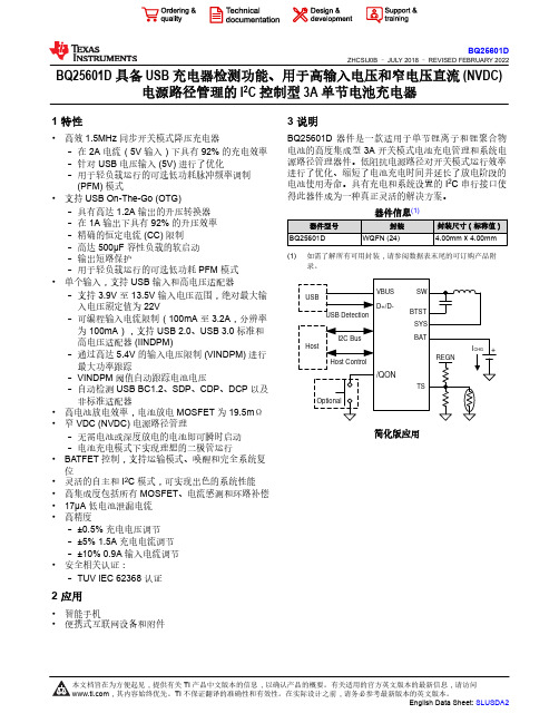
BQ25601D 具备 USB 充电器检测功能、用于高输入电压和窄电压直流 (NVDC) 电源路径管理的 I2C 控制型 3A 单节电池充电器1 特性•高效 1.5MHz 同步开关模式降压充电器–在 2A 电流(5V 输入)下具有 92% 的充电效率–针对 USB 电压输入 (5V) 进行了优化–用于轻负载运行的可选低功耗脉冲频率调制 (PFM) 模式•支持 USB On-The-Go (OTG)–具有高达 1.2A 输出的升压转换器–在 1A 输出下具有 92% 的升压效率–精确的恒定电流 (CC) 限制–高达 500µF 容性负载的软启动–输出短路保护–用于轻负载运行的可选低功耗 PFM 模式•单个输入,支持 USB 输入和高电压适配器–支持 3.9V 至 13.5V 输入电压范围,绝对最大输入电压额定值为 22V–可编程输入电流限制(100mA 至 3.2A,分辨率为 100mA),支持 USB 2.0、USB 3.0 标准和高电压适配器 (IINDPM)–通过高达 5.4V 的输入电压限制 (VINDPM) 进行最大功率跟踪–VINDPM 阈值自动跟踪电池电压–自动检测 USB BC1.2、SDP、CDP、DCP 以及非标准适配器•高电池放电效率,电池放电 MOSFET 为 19.5mΩ•窄 VDC (NVDC) 电源路径管理–无需电池或深度放电的电池即可瞬时启动–电池充电模式下实现理想的二极管运行•BATFET 控制,支持运输模式、唤醒和完全系统复位•灵活的自主和 I2C 模式,可实现出色的系统性能•高集成度包括所有 MOSFET、电流感测和环路补偿•17µA 低电池泄漏电流•高精度–±0.5% 充电电压调节–±5% 1.5A 充电电流调节–±10% 0.9A 输入电流调节•安全相关认证:–TUV IEC 62368 认证2 应用•智能手机•便携式互联网设备和附件3 说明BQ25601D 器件是一款适用于单节锂离子和锂聚合物电池的高度集成型 3A 开关模式电池充电管理和系统电源路径管理器件。

Victron Energy B.V. | De Paal 35 | 1351 JG Almere | The Netherlands E-mail: *********************** | Venus OS supports several types of energy meters, some of which are manufactured and/orstocked by Victron and others that need to be purchased from the manufacturers directly, such as Carlo Gavazzi or ABB.The Energy Meters are used in systems with a GX device to measure the output of a PVInverter, a AC Genset or as a Grid Meter in an ESS installation . It also can be used to measure AC loads.The VM-3P75CT energy meter connects to the GX device via VE.Can or Ethernet and is ready to use out of the box with no configuration required. Alternatively, the EM24 Ethernet meter can be used, provided the meter connects to a local network in such a way that the GX device can reach it. All other Energy Meters listed here connect to a GX device via RS485 either through a wired connection via a RS485 to USB interface or wirelessly via a Zigbee to USB and Zigbee to RS485 converters . Its data is then displayed on a GX device and the VRM portal .To make a selection, first decide if you need a single- or three-phase meter:Which Energy Meter should be selected depends on the installation, the number of phases you want to measure and the maximum current per phase.Examples: For a three-phase utility connection, use a three-phase meter. For a three-phase PV Inverter, use a three-phase meter as well. For a single-phase utility connection, use a single-phase meter or alternatively a three-phase meter; most of them have a single-phase mode. And in an installation with a single-phase utility connection, that also has a PV Inverter that needs measuring with an energy meter, then you can use two pieces of ET112 or use the ET340. If the application exceeds the max. current rating, use an Energy Meter with current transformers. Note that most PV Inverters feature "direct-readout" by the Victron system and thus don't need their output to be measured by an energy meter.Now, based on current, select the model:RequirementMeasurement typeSolutionSingle-phase up to 100A Direct/Shunt ET1XX / EM1XX / ABB B21Three-phase up to 65A/phaseDirect/Shunt ET340 / EM24 / EM340 / EM540 / ABB B23 Single-phase more than 100A/phase Current Transformers Not available, use a 3-phase CT solution Three-phase more than 65A/phaseCurrent TransformersVM-3P75CT / EM24* / EM330 / EM530 / ABB B24* EM24DINAV53DISX only, not stocked by VictronChoose between RS485, VE.Can and/or Ethernet connection:The Ethernet mode of the VM-3P75CT and the EM24 Ethernet will have an advantage ininstallations where an Ethernet network is available. Rather than having to pull an RS485 wire between the main AC distribution board and the storage system, the existing Ethernet can be used. The disadvantage is that this relies on that network functioning properly – in case of issues the storage system will switch to idle mode: passthrough.It's even easier via the VE.Can connection, a direct connection between the VM-3P75CT and the GX device that works completely independently of a network connection.The VM-3P75CT, EM24, EM3XX, EM5XX and ABB meters use vector registration to count energy. This is the preferred method for countries, such as Germany and Austria and most other countries. The other energy meters use arithmetic registration. See FAQ Q8 in the Victron Energy Meter manuals for further details regarding energy counting differences.EM540ET112ET340ABB B21ABB B23/B24Victron VM-3P75CTVictron Energy B.V. | De Paal 35 | 1351 JG Almere | The Netherlands E-mail: *********************** | 4VM-3P75CTVM-3P75CT REL200300100No3 80A CTs VE.Can / Ethernet 100msET112 ET112REL300100000 1 100ADirect/Shunt RS485 750ms ET112DINAV01XS1XET340 ET340REL3003000003 65A per phase2000ms ET340DINAV23XS1XEM540 EM540REL200100100LCD 100ms EM540DINAV23XS1XEM24 EthernetEM24Ethernet REL20020010065A per phase5A per phaseDirect/ShuntCTs Ethernet 600msEM24DINAV23XE1XEM24DINAV53XE1X 3EM111 EM111Not stocked LCD 145ADirect/ShuntRS485750msEM112 EM112100AEM330 1EM3303 5A per phase CTs 1200msEM330DINAV53HS1X27EM330DINAV53HS1PFB27EM340 1EM34065A per phase Direct/Shunt - EM340DINAV23XS1X27EM340DINAV23XS1PFB27 EM530 1EM5305A per phase CTs 100ms EM530DINAV53XS1XEM24 RS485 1EM24RS48565A per phaseDirect/Shunt600ms EM24DINAV93XISXABB B21 1, 2B21 1 65A480ms 2CMA100155R1000 SilverABB B23 1, 2B233 65A per phase 2CMA100169R1000 SilverABB B24 1, 2B246A per phase CTs 2CMA100183R1000 Silver1 Selected models are supported2 Zigbee connection is not supported3 Not stocked by Victron4 Refresh rate = how often the energy meter provides a new value in its registers. Note that the GX device’s latency (the time it takes to read at 9600 baud) is between 180 and 250ms.。
ECP2459
4.5-60V 0.5A 480KHz Step-down converter in a SOT23-6
Preliminary v01 01/2020
Description
The ECP2459 is a monolithic,step-down, switch-mode converter with a built-in power MOSFET. It achieves a 0.5A peak-output current over a wide input supply range with excellent load and line regulation. Current- mode operation provides a fast transient response and eases loop stabilization. Fault condition protections include cycle-by-cycle current limiting and thermal shutdown. The ECP2459 requires a minimal number of readily available, external components and is available in a space saving SOT23-6 package.Feature
Input voltage range : 4.5V~60V
0.5A peak output current
1Ω Internal power MOSFET
Fixed 480KHz frequency
Up to 90% efficiency
1μA shutdown mode
Package Type : SOT23-6 Application
Power meters
Distributed power systems
Industrial power systems
B attery chargers
Pre-regulator for linear regulators
Functional Block Diagram Typical Application
Description
Bootstrap pin for top switch. A 0.1uF or larger capacitor should be connected between this pin and the SW pin to supply current to the top switch and top switch driver.
Ground pin.
Output feedback pin. Input to the error amplifier.Set the output voltage.When the load is short-circuited, FB voltage is lower than 250mV, the return circuit will reduce the oscillation
Typical Characteristics V IN=12V, unless otherwise noted.
VIN=12V, VOUT=5V, L=10μH, TA=25°C, unless otherwise noted.
VIN=12V, VOUT=5V, L=10μH, TA=25°C, unless otherwise noted.
Application Information
Setting Output Voltage
The external resistor divider sets the output voltage (see the Typical Application schematic). Table 1 lists resistors for common output voltages. The feedback resistor (R2) also sets the feedback loop bandwidth with the internal compensation network (see Figure 1). R1 is:
PCB Layout Guide
PCB layout is very important to stability. Please follow these guidelines and use Figure 1 as reference.
1)Keep the path of switching current short and minimize the loop area formed by the input
capacitor, high-side MOSFET, and Schottky diode.
2)Keep the connection from the power ground →Schottky diode→SW pin as short and wide as
possible.
3)Ensure all feedback connections are short and direct. Place the feedback resistors and
compensation components as close to the chip as possible.
4)Route SW away from sensitive analog areas such as FB.
5)Connect IN, SW, and especially GND to large copper areas to cool the chip for improved
thermal performance and longterm reliability. For single layer PCBs, avoid soldering the exposed pad.
Figure 1:PCB Layout
Typical Application Circuit
Figure 3: 5V Output Typical Application Circuit:
Figure 4: 3.3V Output Typical Application Circuit
ECP2459
Package Information
SOT23-6
Note:
1. All dimensions are in millimeters.
2. Package length does not include mold flash, protrusion or gate burr.
3.
Package width does not include flash or protrusion.
4. Lead coplanarity (bottom of leads after forming) shall be 0.10 millimeters max.
5. Pin 1 is lower left pin when reading top mark from left to right.。