ESP-101_伊萨中文手册
- 格式:pdf
- 大小:4.99 MB
- 文档页数:50

Protective Devices Miniature Circuit Breakers PLN4Catalog1.11EATON CORPORATION CA019074ENProtective DevicesMiniature Circuit Breakers PLN4 (MW)• T op-quality miniature circuit breakers 1P+N with a width of 1 module unit requiring little space for installation• Contact position indicator red - green • Guide for secure terminal connection • C omprehensive range of accessories can be mounted subsequently • Rated currents up to 40 A • Tripping characteristics B, C• R ated breaking capacity 4.5 kA according to IEC/EN 60898-1DescriptionSG157112EATON CORPORATION CA019074EN 3EATON CORPORATION CA019074ENSpecifications | Miniature Circuit Breakers PLN6, PLN4Description• High selectivity between MCB and back-up fuse due to low let-through energy • B usbar positioning optionally above or below • Compatible with standard busbar• Switching toggle in colour designating the rated current • M eets the requirements of insulation co-ordination, distance between con-tacts ³ 4 mm, for secure isolation • 1-pole breaking capacityI cn 1 = 3 kA Accessories:Auxiliary switch for subsequent installation ZP-IHK 286052ZP-WHK 286053Tripping signal switch for subsequent installation ZP-NHK 248437Remote control and automatic switching device Z-FW/LP 248296Shunt trip release ZP-ASA/..248438, 248439Undervoltage releaseZ-USA/..248288-248291Busbars:see capter busbar systemsTechnical DataPLN6, PLN4ElectricalDesign according toCurrent test marks as printed onto the device IEC/EN 60898-1Rated voltage U n 230 VAC Rated frequency50/60 Hz Rated breaking capacity according to IEC/EN 60898-1I cnPLN6 6 kA PLN4 4.5 kA Characteristic B, CBack-up fuse>6 kA max. 100 A gL/gG >4.5 kA max. 80 A gL/gG Selectivity class3Endurance electrical components ³ 8,000 switching operationsMechanical Frame size 45 mm Device height 80 mmDevice width 17.5 mm (1MU for 1+N)Mountingquick fastening with 2 lock-in positions on DIN rail IEC/EN 60715Degree of protectionIP20Upper and lower terminals open-mouthed/lift terminalsTerminal protection finger and hand touch safe, DGUV VS3, EN 50274Terminal capacity1-16 mm 2Connection diagram1+N-poleDimensions (mm)Rated current I n (A)TypeDesignationArticle No.Units per package4.5 kA, Characteristic BSG157116PLN4-B6/1N 26317912/12010PLN4-B10/1N 26318012/12013PLN4-B13/1N 26318112/12016PLN4-B16/1N 26318212/12020PLN4-B20/1N 26318312/12025PLN4-B25/1N 26318412/12032PLN4-B32/1N 26318512/12040PLN4-B40/1N26318612/1201+N-pole4.5 kA, Characteristic CSG157116PLN4-C6/1N 26318912/12010PLN4-C10/1N 26319012/12013PLN4-C13/1N 26319112/12016PLN4-C16/1N 26319212/12020PLN4-C20/1N 26319312/12025PLN4-C25/1N 26319412/12032PLN4-C32/1N 26319512/12040PLN4-C40/1N26319612/1201+N-pole Explanation PLN4:P = xPole , LN = Miniature Circuit Breakers 1P+N, 1MU , 4 = 4.5 kA4EATON CORPORATION CA019074EN5EATON CORPORATION CA019074ENShort-circuit Selectivity PLN4In case of short-circuit, there is selectivity between the miniature circuit breakers PLN4 and the upstream fuses up to the specified values of the selectivity limit current I s [kA] (i. e. in case of short-circuit currents I ks under I s only the MCB will trip, in case of short-circuit currents above this value both protective devices will respond).*) basically in accordance with EN 60898-1 D.5.2.bShort-circuit selectivity Characteristic B towards fuse link DII-DIV *)Short-circuit selectivity Characteristic C towards fuse link DII-DIV *)PLN4DII-DIV gL/gG I n [A]20253550638010060.7 1.2 2.9 4.52) 4.52) 4.52) 4.52)100.60.9 1.9 3.1 4.52) 4.52) 4.52)130.50.7 1.5 2.5 4.52) 4.52) 4.52)160.50.7 1.4 2.3 4.3 4.52) 4.52)200.50.7 1.4 2.2 4.0 4.52) 4.52)250.50.6 1.3 2.0 3.8 4.52) 4.52)320.50.6 1.2 1.8 3.4 4.52) 4.52)40<0.51)0.61.1 1.7 3.1 4.52) 4.52)Short-circuit selectivity Characteristic B towards fuse link D01-D03*)Short-circuit selectivity Characteristic C towards fuse link D01-D03*)PLN4DII-DIV gL/gG I n [A]2025355063801002 1.5 3.8 4.52) 4.52) 4.52) 4.52) 4.52)40.7 1.2 3.3 4.52) 4.52) 4.52) 4.52)60.7 1.1 2.6 4.52) 4.52) 4.52) 4.52)100.50.8 1.7 2.8 4.52) 4.52) 4.52)130.50.7 1.5 2.5 4.52) 4.52) 4.52)160.50.6 1.2 2.0 3.6 4.52) 4.52)200.50.61.2 1.8 3.3 4.52) 4.52)25<0.51)0.6 1.1 1.7 3.0 4.52) 4.52)32<0.51)0.6 1.0 1.6 2.8 4.52) 4.52)40<0.51)0.6 1.0 1.5 2.6 4.0 4.52)PLN4D01-D03 gL/gG I n [A]20253550638010060.60.9 2.5 4.52) 4.52) 4.52) 4.52)100.50.8 1.6 3.4 4.52) 4.52) 4.52)130.50.7 1.3 2.7 4.0 4.52) 4.52)160.50.6 1.3 2.5 3.8 4.52) 4.52)20<0.51)0.61.32.43.64.52) 4.52)25<0.51)0.6 1.2 2.3 3.3 4.52) 4.52)32<0.51)0.6 1.1 2.1 3.0 4.52) 4.52)40<0.51)0.6 1.0 2.0 2.8 4.52) 4.52)PLN4D01-D03 gL/gG I n [A]2025355063801002 1.1 2.0 4.52) 4.52) 4.52) 4.52) 4.52)40.60.9 2.7 4.52) 4.52) 4.52) 4.52)60.60.9 2.3 4.52) 4.52) 4.52) 4.52)100.50.7 1.5 3.0 4.52) 4.52) 4.52)130.50.71.32.7 4.0 4.52) 4.52)16<0.51)0.6 1.1 2.23.14.52) 4.52)20<0.51)0.6 1.1 2.1 2.9 4.52) 4.52)25<0.51)0.5 1.0 2.0 2.7 4.52) 4.52)32<0.51)0.5 1.0 1.9 2.6 4.52) 4.52)40<0.51)0.50.9 1.7 2.3 4.0 4.52)1) Selectivity limit current I sunder 0.5 kA2) S electivity limit current I s = rated breaking capacity I cn of the MCBShort-circuit selectivity Characteristic B towards fuse link NH-00*)Short-circuit selectivity Characteristic C towards fuse link NH-00*)PLN4NH-00 gL/gG I n [A]202532354050638010060.50.91.52.33.24.52) 4.52) 4.52) 4.52)10<0.51)0.7 1.2 1.5 2.0 3.1 3.9 4.52) 4.52)13<0.51)0.6 1.0 1.3 1.7 2.5 3.1 4.52) 4.52)16<0.51)0.6 1.0 1.3 1.6 2.4 2.9 4.52) 4.52)20<0.51)0.50.9 1.3 1.5 2.3 2.8 4.3 4.52)25<0.51)0.50.9 1.1 1.4 2.1 2.6 4.0 4.52)32<0.51)0.50.8 1.0 1.3 1.9 2.4 3.6 4.52)40<0.51)0.50.80.9 1.1 1.7 2.2 3.3 4.52)PLN4NH-00 gL/gG I n [A]202532354050638010020.7 2.1 4.52) 4.52) 4.52) 4.52) 4.52) 4.52) 4.52)40.50.9 1.6 2.6 3.7 4.52) 4.52) 4.52) 4.52)60.50.8 1.4 2.1 2.9 4.52) 4.52) 4.52) 4.52)10<0.51)0.6 1.0 1.4 1.9 2.8 3.5 4.52) 4.52)13<0.51)0.60.9 1.3 1.7 2.5 3.1 4.52) 4.52)16<0.51)0.50.7 1.0 1.3 2.0 2.5 3.8 4.52)20<0.51)0.50.70.9 1.2 1.8 2.3 3.5 4.52)25<0.51)0.50.70.9 1.1 1.6 2.1 3.3 4.52)32<0.51)<0.51)0.60.8 1.1 1.5 2.0 3.1 4.52)40<0.51)<0.51)0.60.8 1.0 1.4 1.9 2.9 4.52)Load Capacity PLN4Let-through Energy PLN4Determined according to 60898-1.Maximum let-through energy PLN4, Characteristic BMaximum let-through energy PLN4, Characteristic CLoad capacity in case of MCB block installationCurrent carrying capacity at ambient temperature (I n = 2-13 A)Permitted permanent load at ambient temperature T (°C) with n devices: I DL = I n K T (T)K N (N).Current carrying capacity at ambient temperature (I n = 16-25 A)Current carrying capacity at ambient temperature (I n = 32, 40 A)Number of devices (n)L o a d c a p a c i t y f a c t o r K N500300500100015002000300040005000600070001000015000800090004009007008006001500100030002000500040002000090007000100008000600015000300005000060000400007000080000prospektiver Kurzschlußstrom [A]D u r c h l a ße n e r g i e I t [A s e c ]22prospektiver Kurzschlußstrom [A]D u r c h l a ße n e r g i e I t [A s e c ]22500300500100015002000300040005000600070001000015000800090004009007008006001500100030002000500040002000090007000100008000600015000300005000060000400007000080000Prospective short-circuit current [A]L e t t h r o u g h e n e r g y I 2t [A 2 s e c ]Prospective short-circuit current [A]L e t t h r o u g h e n e r g y I 2t [A2 s e c ]EatonEMEA Headquarters Route de la Longeraie 71110 Morges, Switzerland Eaton.eu© 2020 EatonAll Rights Reserved Printed in AustriaPublication No. CA019074EN Article number 302799-MK July 2023Grafics: SRA, Schrems9010238178694Eaton Industries (Austria) GmbH Scheydgasse 421210 Vienna AustriaFollow us on social media to get the latest product and support information.Eaton is a registered trademark.All other trademarks are property of their respective owners.To contact us please visit https:///contacts For technical questions please contact your local Eaton team.Changes to the products, to the information contained in thisdocument, and to prices are reserved; as are errors and omissions.Only order confirmations and technical documentation by Eaton is binding. Photos and pictures also do not warrant a specific layout or functionality. Their use in whatever form is subject to prior approval by Eaton. The same applies to trademarks (especially Eaton, Moeller,and Cutler-Hammer). The Terms and Conditions of Eaton apply, as referenced on Eaton Internet pages and Eaton order confirmations.Eaton is an intelligent power management company dedicated toimproving the quality of life and protecting the environment for people everywhere. We are guided by our commitment to do business right, to operate sustainably and to help our customers manage power - today and well into the future. By capitalizing on the global growth trends of electrification and digitalization, we’re accelerating the planet’s transition to renewable energy, helping to solve the world’s most urgent power management challenges, and doing what’s best for our stakeholders and all of society.For more information, visit .。
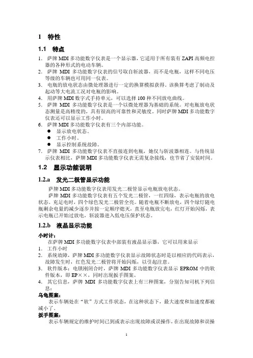
1 特性1.1 特点1.萨牌MDI多功能数字仪表是一个显示器,它适用于所有装有ZAPI高频电控器的各种形式的电动车辆。
2.萨牌MDI多功能数字仪表的信号取自斩波器,而不是电瓶,这样不同电压等级的车辆也可用同一仪表。
3.电瓶的放电状态由微处理器进行一定的换算模拟获得。
该换算考虑了制动及起动等大电流工况对电瓶的影响。
4.用萨牌MDI数字式手持单元,可以选择100种不同放电曲线。
5.萨牌MDI多功能数字仪表是一个以微处理器为基础的系统。
对电瓶放电状态测量是高精度的,具有很高的可靠性和灵敏度。
同时萨牌MDI多功能数字仪表还可以显示工作小时。
6.萨牌MDI多功能数字仪表有三个内部功能。
●显示放电状态。
●工作小时。
●显示控制系统故障。
7.萨牌MDI多功能数字仪表不直接连到电瓶,她仅与斩波器相连。
与传统显示仪表相比,萨牌MDI多功能数字仪表无需复杂接线,也节省了安装时间。
1.2 显示功能说明1.2.a 发光二极管显示功能萨牌MDI多功能数字仪表用发光二极管显示电瓶放电状态。
萨牌MDI多功能数字仪表有五个发光二极管,一红四绿,表示电瓶的放电状态。
充足电时,四个绿色发光二极管全亮。
随着电瓶不断放电,四个绿灯随电瓶剩余电量的减少逐步并按一定顺序熄灭,直至电瓶放完电,红灯开始闪烁,表示电瓶已开始过放电,斩波器进入低电压保护状态。
1.2.b 液晶显示功能小时计:在萨牌MDI多功能数字仪表中部装有液晶显示器,它可以用来显示1.工作小时2.系统故障,萨牌MDI多功能数字仪表显示故障状态时是以相应的代码表示,故障发生时,红色发光二极管将开始闪烁,以引起注意。
3.软件版本:电锁刚闭合时,萨牌MDI多功能数字仪表显示EPROM中的软件版本,即EP××,同时出现扳手图案。
4.其它信息,萨牌MDI多功能数字仪表上有三种图案,分别告知司机下列信息:乌龟图案:表示车辆处在“软”方式工作状态,在这种状态下,最大速度和加速度都被减小了。
说明非常感谢您使用鹰眼电子科技有限公司的CO B—E201A系列产品,在安装、操作、维修或检查本产品之前请务必要彻底阅读本说明书。
本手册内容和规格可能会根据机器版本(包括硬件和软件)而更变,恕不另行通知。
未经鹰眼电子科技有限公司许可,本手册任何部分都不可以任何形式或者通过电子或机械方法复制。
目录1.安全措施- - - - - - - - - - - - - - - - - - - - - - 3 -2.界面操作- - - - - - - - - - - - - - - - - - - - - - 4 –2-1. 主界面操作- - - - - - - - - - - - - - - - - - - - - 4 –2-2. 参数设定面板- - - - - - - - - - - - - - - - - - - - 4 –2-3. 运动控制面板- - - - - - - - - - - - - - - - - - - - 12 –2-4. 界面调试操作- - - - - - - - - - - - - - - - - - - - 13 –3.控制面板介绍- - - - - - - - - - - - - - - - - - - - - - 16 –3-1.电源控制面板- - - - - - - - - - - - - - - - - - - - 16 –3-2. 点胶快捷键面板介绍- - - - - - - - - - - - - - - - - 17 –3-3.参数控制面板- - - - - - - - - - - - - - - - - - - - - 17 –3-3-1.气路系统- - - - - - - - - - - - - - - - - - - - - - 18 –3-3-2. 温控系统- - - - - - - - - - - - - - - - - - - - - 18 –备注:设备易损件及其使用寿命- - - - - - - - - - - - - - - 19 –4.常见故障及其排除方法- - - - - - - - - - - - - - - - - - 20 –5.机台的保养方法- - - - - - - - - - - - - - - - - - - - - 21 –6.相对应标准件清单- - - - - - - - - - - - - - - - - - - - 22 –7.整机检修问题备忘录- - - - - - - - - - - - - - - - - - - 24 -1.安全措施1-1.机器搬运及安装注意事项:1.由于机器比较重,建议在搬运时要由4人以上进行。
目录手册使用说明(必读)--------------------------------------------------------------- 3 第一章概述 ------------------------------------------------------------------------ 4 第二章主要参数 ------------------------------------------------------------------- 5 第三章安装、接口与数据格式---------------------------------------------------- 6一、仪表前、后功能示意图 -------------------------------------------------- 6二、传感器与仪表的连接 ----------------------------------------------------- 8三、输入输出接口--------------------------------------------------------------- 9四、大屏幕显示接口 ----------------------------------------------------------- 9五、串行通讯接口-------------------------------------------------------------- 10六、模拟量输出----------------------------------------------------------------- 11七、打印与存储----------------------------------------------------------------- 13 第四章标定---------------------------------------------------------------------------- 14 第五章参数设置 --------------------------------------------------------------------- 16一、【SEt 0】查询类参数 ------------------------------------------------- 16二、【SEt 1】一般类参数 ------------------------------------------------- 19三、【SEt 2】控制参数 ---------------------------------------------------- 21四、【SEt 3】记录打印 ---------------------------------------------------- 26 第六章操作说明 --------------------------------------------------------------------- 28一、开机及开机置零 ---------------------------------------------------------- 28二、手动置零-------------------------------------------------------------------- 28三、除皮 -------------------------------------------------------------------------- 28四、日期与时间的设置 ------------------------------------------------------- 28五、启动/停止 ------------------------------------------------------------------- 28六、峰值保持-------------------------------------------------------------------- 29七、输入输出功能-------------------------------------------------------------- 29八、常用参数快速设置 ------------------------------------------------------- 29 第七章控制过程详解-------------------------------------------------------------- 30一、模式0(1种配料的加法模式) -------------------------------------- 30二、模式1(1种配料的减法模式) -------------------------------------- 32三、模式2(两种料加法秤)----------------------------------------------- 34四、模式3(分选模式) ----------------------------------------------------- 36第八章维护保养及注意事项 ----------------------------------------------------41 附录一出错信息提示--------------------------------------------------------------43 附录二大屏幕数据波形图及格式------------------------------------------------44 附录三串行通信-指令应答方式的数据格式 --------------------------------45 附录四常见问题处理方法 ---------------------------------------------------------47亲爱的用户:在使用仪表前,敬请仔细阅读说明书!- 2 -手册使用说明(必读)为客户能正确使用仪表,用户必须了解本手册中相关内容。
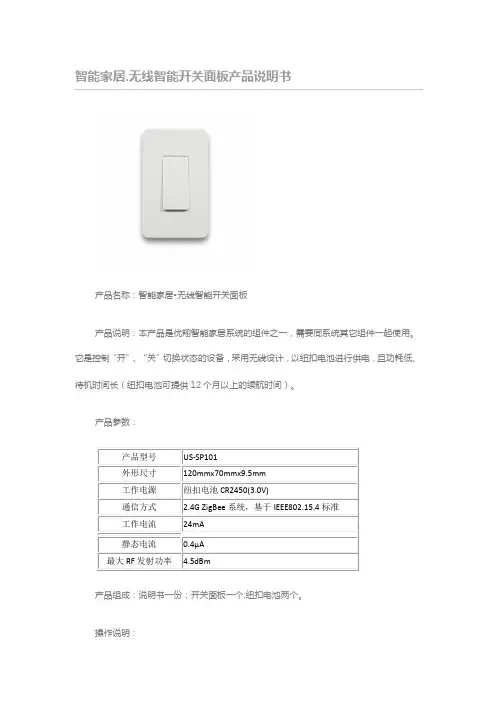
智能家居.无线智能开关面板产品说明书
产品名称:智能家居•无线智能开关面板
产品说明:本产品是优翔智能家居系统的组件之一,需要同系统其它组件一起使用。
它是控制“开”、“关”切换状态的设备,采用无线设计,以纽扣电池进行供电,且功耗低、待机时间长(纽扣电池可提供12个月以上的续航时间)。
产品参数:
产品组成:说明书一份;开关面板一个;纽扣电池两个。
操作说明:
1、平置开关面板,用针或其他辅助工具轻戳位于按钮右下方的小孔,弹出电池插槽;
2、取掉纽扣电池背面的绝缘片,将纽扣电池装入,再推入插槽、合紧;
3、使用随产品附赠的泡棉胶,将开关面板粘贴固定在合适的位置;
4、安装完成。
图解说明:
注意事项:
1、请不要擅自对产品进行拆卸和维修;
2、请不要将本产品置于高温高压等极端环境中;
3、请正确安装纽扣电池,切勿接反;
4、请将本产品放置于婴孩不能触及的场所;
5、请保持产品干燥,不要放置于潮湿的环境中;
厦门同人物联技术有限公司(Xiamen Tongren IOT Technology Co.,Ltd.)二十四小时服务热线:4008888022
网址:。

ELAC DS-C101W-G说明书重要安全说明1.一般信息•请阅读并遵守这些安全说明。
•请妥善保管,以便日后参考。
•请遵守装置上和手册中的所有警告。
使用前请检查扬声器是否损坏。
本装置必须处于完美的工作状态。
损坏的部件可能导致人身伤害。
2.仅按指示使用•按照手册中的说明连接设备。
3.地点•只需将设备安装在一个水平面上•在为该设备选择位置时,不要将其放置在有以下情况的地方。
•在阳光直射下•非常湿润•易受振动影响•特别热或特别冷不要堵塞任何通风口。
按照制造商的说明进行安装。
•请勿将本设备安装在封闭的机架或封闭的橱柜中。
•不要把燃烧的蜡烛放在设备上或附近。
•不要在变压器附近安装设备,因为电磁杂散场会导致低音扬声器出现嗡嗡声。
4.服务危险!不要打开机柜,因为部件和导体可能带有危险等级的电流!请不要打开机柜。
只能由合格的服务人员进行维修。
当扬声器以任何方式被损坏时,如电源线或插头损坏,或有液体溢出或物体落入扬声器时,需要进行维修。
扬声器被暴露在雨中或湿气中,不能正常操作,或被掉落。
为减少电击的危险,请勿打开扬声器。
维修工作只能由合格的服务人员进行。
5.清洁注意:只能用柔软、光滑的布或防尘刷清洁。
不要使用洗刷剂、酒精、苯、家具上光剂或其他药剂进行清洁!现代家具通常涂有多种清漆和塑料,可以用化学制剂处理。
这些药剂中有些含有降解或软化橡胶脚的物质。
6.废弃处理包装是由可回收材料制成的。
请以环保的方式进行处理。
在使用寿命结束时,不要将扬声器与标准的家庭垃圾一起处理。
必须按照当地法律规定对扬声器进行回收。
由于本设备含有宝贵的原材料,请向当地政府询问有关回收的进一步信息。
在弃置前请禁用扬声器。
7.权力本设备只能连接到箱体后面板上所列的电压。
连接到任何其他电压可能会对亚低音扬声器造成不可逆的损坏,并且会导致保修失效。
不建议使用插头适配器,因为它们可能会允许连接到本低音炮背面所印的电压以外的电压。
8.无线发射器的合规信息无线电认证号前的术语"IC:"仅表示符合加拿大工业部的技术规范。
WinPAC ISaGRAF PAC 快速上手手冊WinPAC-8xx7或WP-8xx7 為 WP-8147/8447/8847/8137/8437/8837的簡稱。
WinPAC-8xx6或WP-8xx6 為 WP-8146/8446/8846/8136/8436/8836的簡稱。
重要1. WP-8xx7/8xx6 的插槽0 ~ 7 只支援高卡的 I-8K 與 I-87K I/O 模組。
請參考 WP-8xx7 CD: \napdos\isagraf\wp-8xx7\chinese_manu\“chinese_wp-8x47_datasheet.pdf”2. WinPAC-8xx7 需設定為固定 IP 位址。
(不可使用 DHCP)3. 如果不使用 WP-8xx7的 LAN2,需將 LAN2 設定為 Disable (請參考附錄D)。
4. 建議使用工業級乙太網路交換器NS-205或NS-208來連接WP-8xx7/8xx6。
注意泓格科技股份有限公司對於因為使用本系列產品所造成的任何損害並不負任何法律上的責任,本公司並保留在任何時候修訂本書且不需通知的權利。
泓格科技股份有限公司將儘可能地提供本系列產品可靠而詳盡的資訊。
然而,本公司並無義務需提供此系列產品詳盡的應用資訊,或對因非法使用本系列產品所遭受的損害負任何責任。
商標與著作權本書所提所有公司商標,商標名稱及產品名稱分別屬於該商標或名稱的擁有者所有。
開發軟體兩種選項:- ISaGRAF: 3.4x或3.5x版,符合IEC 61131-3標準。
LD, ST, FBD, SFC, IL 與 FC。
- 非ISaGRAF: Microsoft EVC++4.0 或 2008/2005/2003 (, C#.net)。
參考資料- ISaGRAF English User’s Manual:WinPAC-8xx7 CD: \napdos\isagraf\wp-8xx7\english_manu\"user_manual_i_8xx7.pdf" 與 "user_manual_i_8xx7_appendix.pdf"(附錄)- ISaGRAF中文進階使用手冊:WinPAC-8xx7 CD: \napdos\isagraf\wp-8xx7\chinese_manu\"chinese_user_manual_i_8xx7.pdf" 與"chinese_user_manual_i_8xx7_appendix.pdf"(附錄)- 更多網頁資訊: /products/PAC/i-8000/isagraf_c.htm技術支援請連絡當地的經銷商或 E-mail 問題至****************** .常見問答集請參考FAQ : /faq/isagraf.htm版本: 1.1 版, 2009年 7月著作者: Chun Tsai; 編譯者: Eva Li版權所有泓格科技股份有限公司,2009年7月起,保留所有權利。
智能型调光硅箱操作手册目录1. 一般说明 (2)2. 保修与服务 (2)3. 概述 (3)4. 产品简介 (3)5. 性能与特点 (3)6. 功能键的定义 (5)7. 操作菜单 (5)8. 正常运行状态 (5)9.1 DMX Address(设置DMX开始地址) (6)9.2 Sel Curve(选择通道曲线) (6)9.3 Def Curve(定义自定义曲线) (7)9.4 Set Value(设置手动调光值) (8)9.5 LCD Contrast(调整LCD对比度) (9)9.6 SW Version(查看软件版本号) (9)9.7 RST Config(复位用户设置) (10)1. 一般说明:⇩请仔细阅读本手册的用法说明,它提供了有关安全的安装、应用和维护的重要信息。
⇩请妥善保存本手册,以备日后查询。
如果该设备被转卖或更换操作员,请确保设备与手册不分离,使操作者阅悉它的操作及相关指令。
⇩禁止易燃液体、水或金属粉末物质进入该设备。
⇩禁止拆除或修改该设备。
⇩如果不慎有液体进入机箱内,请立刻切断设备电源。
⇩如果有严重的操作问题,请立刻关闭机器,并即刻与TINHAO经销商或代理商联系。
⇩禁止打开该设备,机箱内没有用户使用的部分。
⇩禁止用户自己修理该设备。
不合格的修理人员可能损害设备或引起不正当的操作。
⇩如果设备有问题,请即刻与你最近的授权服务中心或制造商联系。
★务必坚持原配件进行安装维护!2. 保修与服务⇩自购买之日起一年内,若发生任何制造工艺或元器件问题造成的损坏,本公司提供免费的维修服务。
⇩由于粗心或不正当操作导致的故障,不属于保修服务之列。
⇩未经授权就擅自改装或修改本设备的,本保修服务将自动无效。
⇩运输费用和相关风险由设备所有者承担。
⇩本承诺服务不包括附件、辅助装置以及维修人员上门服务费。
⇩如果设备已被未经许可的人损坏或修理,本保证将不再有效。
3. 概述:AT1000+智能型调光硅箱是根据国内市场的需求,在中英合作下共同研制开发的调光硅箱,其重量轻和在防震技术上的完善及在维修方面的便利,解决了目前国内在流动硅箱方面存在的一大难题。
AIG-101Series2-port Modbus RTU/ASCII/TCP to MQTT/Azure/AWS cloud-ready gatewaysFeatures and Benefits•Supports generic MQTT client•Supports MQTT connection with built-in device SDKs for Azure/AWS cloud•Supports Modbus RTU/ASCII/TCP master/client•Supports Modbus TCP server•Built-in network traffic monitoring and diagnostic tool for easytroubleshooting•Supports data buffering using store and forward and datalogger•Seamless integration with Moxa ioLogik/UPort devices to easily extend I/Oand serial interfaces•Built-in data processing function to eliminate programming efforts•-40to70°C operating temperature range•LTE Cat.1US,EU,and APAC models availableCertificationsIntroductionThe AIG-101Series gateways are entry-level IIoT gateways that connect Modbus RTU/ASCII/TCP devices to cloud platforms and applications such as Azure,AWS,and MQTT.The AIG-101as a Modbus master can integrate existing Modbus devices with cloud platforms,effortlessly collecting and transmitting data to the Azure and AWS clouds.Moreover,the gateways also support the Modbus TCP slave mode,enabling simultaneous transmission of data to a cloud platform and local SCADA system.Effortless Extension of I/O and Serial InterfacesAs the number of field sites increases,additional I/O or serial interfaces are required to connect devices,such as sensors,meters,and inverters,for collecting and processing the large amount of data that is generated.A typical approach is to install remote I/O and device servers to extend the interfaces,but the configuration settings required can be a nightmare for most users.To provide an extremely simple configuration process for interface extension,AIG-101gateways have better integration and come with an intuitive wizard that can configure Moxa ioLogiks and UPorts with just a few clicks.Built-in Ready-to-use Data Preprocessing Functions,No Coding RequiredEnergy Management Systems mainly collect energy data such as average power generation and energy efficiency.This data is then used to display on-site conditions,observe the energy trend,and optimize energy usage.Most edge systems require additional programming to process the data required by energy management system.The AIG-101can preprocess the edge data and directly send meaningful data to the energy management systems.The intuitive UI enables easy configuration of the IIoT gateway settings to collect and process data.Secure Remote Access Reduces Maintenance CostsThe AIG-101comes with powerful troubleshooting tools to diagnose issues with protocol statuses and capture and analyze traffic packets, enabling engineers to remotely identify the root cause of issues and quickly bring the operation back to normal.The tools also provide secure remote access to the AIG-101to enable the maintenance engineers to directly access it,saving a lot of time and effort and reducing system downtime in energy management systems.AppearanceAIG-101-T-AP/EU/USAIG-101-TSpecificationsEthernet Interface10/100BaseT(X)Ports(RJ45connector)2,Auto MDI/MDI-X connectionMagnetic Isolation Protection 1.5kV(built-in)Ethernet Software FeaturesIndustrial Protocols Modbus TCP Client(Master)/Server(Slave)Generic MQTTAzure IoT DeviceAWS IoT CoreConfiguration Options Web Console(HTTP/HTTPS)Time Management NTP ClientGPSSerial InterfaceNo.of Ports2Connector DB9maleSerial Standards RS-232/422/485Baudrate300bps to921.6kbpsData Bits7,8Parity None,Even,Odd,Space,MarkStop Bits1,2Flow Control RTS/CTSSerial SignalsRS-232TxD,RxD,RTS,CTS,DTR,DSR,DCD,GNDRS-422Tx+,Tx-,Rx+,Rx-,GNDRS-485-2w Data+,Data-,GNDRS-485-4w Tx+,Tx-,Rx+,Rx-,GNDCellular InterfaceCellular Standards LTE Cat.1Cellular Antenna Connectors SMA x2SIM Format Nano SIMNo.of SIMs2GPS Antenna Connectors SMA x1Band Options US Model:LTE Bands:Band2(1900MHz)/Band4(1700MHz)/Band5(850MHz)/Band12(700MHz)/Band13(700MHz)/Band14(700MHz)/Band66(1700MHz)/Band71(600MHz)UMTS Bands:2(1900MHz)/Band4(1700MHz)/Band5(850MHz)Carrier Approval:Verizon,AT&TEU Model:LTE Bands:Band1(2100MHz)/Band3(1800MHz)/Band7(2600MHz)/Band8(900MHz)/Band20(800MHz)/Band28(700MHz)UMTS Bands:Band1(2100MHz)/Band3(1800MHz)Band8(900MHz)AP Model:LTE Bands:Band1(2100MHz)/Band3(1800MHz)/Band5(850MHz)/Band8(900MHz)/Band28(700MHz)UMTS Bands:Band1(2100MHz)/Band5(850MHz)/Band8(900MHz)Serial Software FeaturesIndustrial Protocols Modbus RTU/ASCII MasterModbus RTU/ASCIIMode MasterFunctions Supported1,2,3,4,5,6,15,16,23Max.No.of Commands256per portModbus TCPMode Server(Slave)Client(Master)Functions Supported1,2,3,4,5,6,15,16,23Max.No.of Client Connections4Max.No.of Server Connections64Max.No.of Commands1500Generic MQTT ClientVersions Supported v3.1.1v3.1QoS Levels0,1,2Authentication Methods Username and passwordSecure Transmission TLS1.0TLS1.1TLS1.2Native Capabilities Keep AliveRetain MessageClean SessionWill and TestamentMoxa Functions Store and ForwardCustom PayloadRemote API InvocationAzure IoT DeviceConnection Protocols Supported MQTTMQTT over WebSocketsAMQPAMQP over WebSockets Authentication Methods Symmetric KeyX.509CertificateAzure Direct Methods RebootSoftware UpgradeRemote API InvocationMoxa Functions Store and ForwardCustom PayloadAWS IoT CoreQoS Levels0,1Authentication Methods X.509CertificatePrivate KeyTrusted Root CANative Capabilities Keep AliveMoxa Functions Store and ForwardCustom PayloadCommands Invokable Via Jobs RebootSoftware UpgradeRemote API InvocationMemorymicroSD Slot Up to32GB(SD2.0compatible)Max.No.of Tags Supported:1500Power ParametersInput Voltage9to36VDCPower Connector Screw-fastened Euroblock terminalPower Consumption8W(max.)Physical CharacteristicsDimensions128.5x89.1x41mm(5.06x3.51x1.61in)Housing MetalInstallation DIN-rail mountingWall mounting(with optional kit)Weight AIG-101-T:492g(1.08lb)AIG-101-T-AP/EU/US:512g(1.13lb)Environmental LimitsAmbient Relative Humidity5to95%(non-condensing)Operating Temperature-40to70°C(-40to158°F)Storage Temperature(package included)-40to85°C(-40to185°F)Standards and CertificationsEMC EN55032/35EMI CISPR32,FCC Part15B Class AEMS IEC61000-4-2ESD:Contact:4kV;Air:8kVIEC61000-4-3RS:80MHz to1GHz:10V/mIEC61000-4-4EFT:Power:2kV;Signal:1kVIEC61000-4-5Surge:Power:1kV;Signal:1kVIEC61000-4-6CS:10VIEC61000-4-8PFMFSafety IEC62368-1UL62368-1EN62368-1Shock IEC60068-2-27Vibration IEC60068-2-645Grms@5to500Hz,random wave,1hr per axis(without USB devices attached) Cellular Standards EN303413(GPS)EN301908-1(WCDMA/LTE)EN301908-2/-13(WCDMA/LTE)EN301489-1/-19EN301489-1/-52EN62311Radio Frequency FCCPTCRBRCMCarrier Approvals VerizonAT&TGreen Product RoHS,CRoHS,WEEEMTBFTime566,458hrsStandards Telcordia SR332WarrantyWarranty Period5yearsDetails See /warrantyPackage ContentsDevice1x AIG-101Series gatewayCable1x terminal block to power jack converterInstallation Kit1x DIN-rail kitDocumentation1x quick installation guide1x warranty cardDimensionsOrdering InformationModel Name LTE BandAIG-101-T––AIG-101-T-AP Cat.1APAIG-101-T-EU Cat.1EUAIG-101-T-US Cat.1US Accessories(sold separately)Power AdaptersPWR-12150-AU-SA-T Locking barrel plug,12VDC,1.5A,100to240VAC,AU plug,-40to75°C operating temperature PWR-12150-CN-SA-T Locking barrel plug,12VDC,1.5A,100to240VAC,CN plug,-40to75°C operating temperature PWR-12150-EU-SA-T Locking barrel plug,12VDC,1.5A,100to240VAC,EU plug,-40to75°C operating temperaturePWR-12150-UK-SA-T Locking barrel plug,12VDC,1.5A,100to240VAC,UK plug,-40to75°C operating temperature PWR-12150-USJP-SA-T Locking barrel plug,12VDC1.5A,100to240VAC,US/JP plug,-40to75°C operating temperature AntennasANT-LTE-ASM-02GPRS/EDGE/UMTS/HSPA/LTE,2dBi,omnidirectional rubber-duck antennaANT-LTEUS-ASM-01GSM/GPRS/EDGE/UMTS/HSPA/LTE,1dBi,omnidirectional rubber-duck antenna©Moxa Inc.All rights reserved.Updated May04,2023.This document and any portion thereof may not be reproduced or used in any manner whatsoever without the express written permission of Moxa Inc.Product specifications subject to change without notice.Visit our website for the most up-to-date product information.。
串口以太网服务器MWT101/2系列用户手册(使用前请先阅读本手册)版本号:2.0.1重要声明本公司将尽可能地提供本系列产品可靠而详尽的资讯,努力使本手册中提供的信息准确和适用,然而本公司并不对这些信息的使用承担任何责任,也不对这些信息的使用承担任何连带责任。
本公司并无义务提供此系列产品详尽的应用资讯,或对因非法使用本系列产品所遭受的损害负任何责任。
本公司保留在不事先通知情况下更改本使用手册全部或部分内容的权力。
由于产品和技术的不断更新、完善,本资料中的内容可能与实际产品不完全相符,敬请谅解。
如需查询产品的更新情况,请查询本公司网站或直接与本公司业务代表联系。
商标&著作权本书提到的所有公司商标、商标名称及产品名称分别属于该商标或名称的拥有者所有。
1目录一、产品介绍 (3)1、产品概述 (3)2、简明特点 (3)3、外形图及指示灯说明 (4)4、引脚定义 (6)二、产品应用 (8)1、应用概述 (8)2、跳线说明 (9)3、接线说明 (9)4、设备配置 (11)5、设备应用 (16)1)通信帧说明 (16)2)使用方式 (17)6、安装尺寸 (19)7、常见故障排除方法 (19)三、选型指南 (21)1、电源配置 (21)2、产品型号定义 (21)2一、产品介绍1、产品概述重要设备联网是工厂企业发展的趋势。
MWT101/2系列串口以太网服务器的主要功能就是将标准的串口总线数据(RS-232、RS-422、RS-485)与标准的支持TCP/IP协议的以太网数据进行双向转换,用来解决普通串口设备在Internet/Intranet上的联网问题。
MWT101/2系列包含如下几种型号:型号说明MWT101-A 一路串口信号与以太网的双向转换,非隔离型MWT101-B 一路串口信号与以太网的双向转换,隔离型MWT102-A 二路串口信号与以太网的双向转换,非隔离型MWT102-B 二路串口信号与以太网的双向转换,隔离型以上几种型号大部分功能与特性是一致的,有不同的地方会特别说明。