3KASMC22中文资料
- 格式:pdf
- 大小:93.40 KB
- 文档页数:5

配线产品系列中心机房子系统1.GPXKA-Z 型光纤总配架医用在新建机房独立光纤跳接场,现有机房独立光纤跳接场。
产品采用传统MDF 式的线缆管理方式、即直列模块部分为外线侧,提供室外光缆固定、汇流、熔接、与终端功能,横列模块部分为内线侧,提供室内光缆的终端、调度与管理功能。
采用前后双面操作,敞开式结构,上下均可进缆线。
尺寸外线侧内线侧总容量直列单元72芯托盘数量最大芯数横列单元96芯最大芯数2000*720*600954648657612242000*720*6001060720767213922000*720*6001272864876816322.GPXKA-T型光纤熔配为中心局机房,接入局点机房等需要在一个架体内进行分光、熔纤、配纤等工作的场景;采用正面操作,全/半封闭结构,上下均可进缆。
3.ZHGK型综合柜19和21英寸标准安装机柜,提供机房中的各种通信设备提供可靠地安装和保护的设备。
4.接续单元箱应用环境:19英寸安装,适用于综合柜和GPXKA-Ta型光纤熔配架。
5.电源分配单元适用于综合柜,提供引入电源的连接、分配和保护6.音频部件应用环境:适用于综合柜,提供引入电源的连接、分配和保护。
名称型号尺寸容量备注音频部件JPXK-A100H90*W260*D482内线128外线100选配告警单元,保安单元等音频部件JPXK-A100H90*W400*D482内线192外线200音频部件JPXK-A100H90*533*D482内线256外线300音频部件JPXK-A100H90*W711*D482内线384外线400音频部件JPXK-A100H90*W1020*D482内线512外线6007.数字单元体应用环境:西门子或NEC 制式,19英寸安装,适用于综合柜,提供同轴电缆的成端和调度。
馈线光缆子系统1.传统型光缆交接箱光缆交接箱(传统型)应用环境:为光传输网络、光接入网需要实现光缆、光纤的连接与调度的场景,实现短接主干光缆与配线光缆、并可放置光分路器的功能,箱体材质为不锈钢或SMC型。
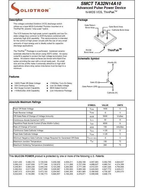
Performance Characteristics T=25o C unless otherwise specified MeasurementsJParameters Symbol Test Conditions Min.Typ.Max.Units Anode to Cathode Breakdown Voltage V(BR)V GK=-5, I A=1mA 1400V Anode-Cathode Off-State Current i D V GE=-5V, V AK=1200V T C=25o C<10100uAT C=150o C2501000uA Gate-Cathode Turn-On Threshold Voltage V GK(TH) V AK=V GK, I AK=1mA 0.7V Gate-Cathode Leakage Current I GK(lkg)V GK=+/-20V500nA Anode-Cathode On-State Voltage V T I T=32A, V GK=+5V T C=25o C 1.5 2.0V(See Figures 1,2 & 3)T C=150o C 1.3 1.5V Input Capacitance C ISS6nF Turn-on Delay Time t D(ON)0.2uF Capacitor Discharge50100nS Rate of Change of Current dI/dt T J=25o C, V GK= -5V to +5V75kA/uSec Peak Anode Current I P V AK=800V, RG=4.7Ω3500A Discharge Event Energy E DIS L S= 7nH (See Figures 4,5 & 6)32mJ Turn-on Delay Time t D(ON)0.2uF Capacitor Discharge50100nS Rate of Change of Current dI/dt T J=150o C, V GK= -5V to +5V110kA/uSec Peak Anode Current I P V AK=1200V, RG=4.7Ω4000A Discharge Event Energy E DIS L S= 7nH (See Figures 4,5 & 6)70mJ Junction to Case Thermal Resistance RAnode (bottom) side cooled (Note 1.)0.08o C/WθJCJunction to Case Thermal Resistance RCathode-Gate (top) side cooled (Note 2.) 1.5o C/WθJCNotes:1. Case Exterior Assumed to be 0.002" of 63sn/37pb solder applied directly to Anode. (See Figure 7.)2. Case Exterior Assummed to be 0.002" of 63sn/37pb solder applied directly to cathode bond area of thinPak. (See Figure 7.) Typical Performance Curves (unless otherwise specified)Figure 1. On-State Characteristics Figure 2. On-State CharacteristicsFigure 3. Predicted High Current On-State CharacteristicsFigure 4. Turn-On Delay Characteristics Figure 5. Turn-On Delay Characteristics R G=4.7Ω - 500Ω, T J=25o C R G=4.7Ω & 50Ω, T J=25o C & 150o CFigure 6. 0.2uF Discharge Pulse Performance Characteristics (See Figure 9.)Figure 7. Transient Thermal Impedance ResponseA2. Calculation of Pulses to Failure for Intermediate/Long Pulse Widths(Bottom) Side Interface(Top) Side InterfaceDevice Junction。
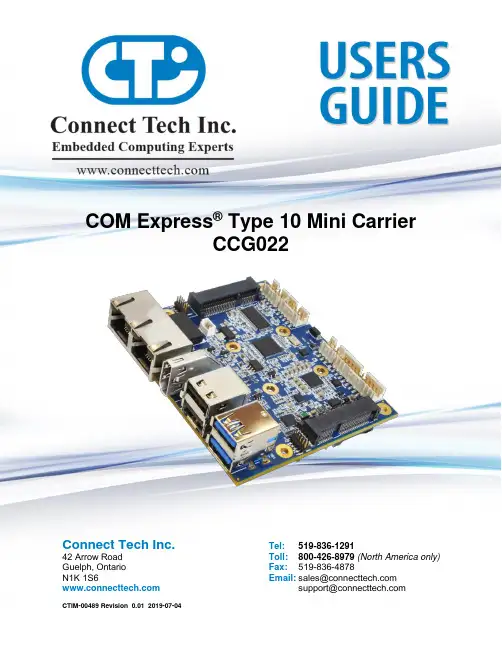
COM Express® Type 10 Mini CarrierCCG022Connect Tech Inc.Tel:519-836-129142 Arrow Road Toll:800-426-8979 (North America only) Guelph, Ontario Fax:519-836-4878N1K 1S6 Email:********************************************Table of ContentsTable of Contents (1)Preface (4)Disclaimer (4)Customer Support Overview (4)Contact Information (4)Limited Product Warranty (5)Copyright Notice (5)Trademark Acknowledgment (5)ESD Warning (6)Revision History (6)Introduction (7)Product Features and Specifications (7)Part Numbers / Ordering Information (8)Product Overview (9)CCG022 Block Diagram (9)Connector Summary & Locations (10)CCG022 Top View (10)CCG022 Bottom View (10)Jumper Summary (11)Detailed Feature Pinouts and Functional Descriptions (12)COM Express Module (12)Display Outputs (13)LVDS Video Connector (13)LVDS Backlight Power Connector (14)HDMI Video Connector (15)USB (16)USB 2.0 Port Connectors (16)USB 3.0/2.0 Port Connectors (16)10/100/1000 Ethernet (GBE) Connector (17)Software Support for the Intel 82574 (17)Serial (18)RS-232/485 Connector (18)RS-232/485 Jumper Configuration (19)J1 – RS-232/485 Jumper Block (19)Serial Line Modes (19)Examples (19)Audio (20)Software Support for the CS4207 (20)microSD Card Connector (21)mini PCIe & mSATA Slots (22)Dual Function mini PCIe mSATA Slots (22)Half and Full Length mini PCIe / mSATA module Installation (23)Standoff and Screw Assembly Details (23)CCG022 – External Hard Drive Installation (24)mini pcie / mSATA Connector Pinout (25)System Miscellaneous (26)System Connector (26)J2 – System Jumper Block (26)Input Power & Control (27)RTC Battery (27)Typical Hardware Installation Procedure (28)On-board Indicator LED (28)Power Consumption and Thermals (29)Current Consumption (29)Thermal Properties (30)Mechanical Drawings & Models (31)Cable Kits (32)CCG022 Cable Kit - CKG044 –“Full” Cable Kit (32)Appendix A – COM Express Signal/Pinout Connection Details (33)PrefaceDisclaimerThe information contained within this user’s guide, including but not limited to any product specification, is subject to change without notice.Connect Tech assumes no liability for any damages incurred directly or indirectly from any technical ortypographical errors or omissions contained herein or for discrepancies between the product and the user’s guide.Customer Support OverviewIf you experience difficulties after reading the manual and/or using the product, contact the Connect Tech reseller from which you purchased the product. In most cases the reseller can help you with product installation and difficulties. In the event that the reseller is unable to resolve your problem, our highly qualified support staff can assist you. Our support section is available 24 hours a day, 7 days a week on our website at:/support/. See the contact information section below for more information on how to contact us directly. Our technical support is always free.Contact InformationMail/CourierConnect Tech Inc.Technical Support42 Arrow RoadGuelph, OntarioCanada N1K 1S6Email/Internet********************************************Note:Please go to the Resource Center or the Support Center on the Connect Tech website for productmanuals, installation guides, device driver software and technical tips.Submit your technical support questions to our customer support engineers via the Support Center on the Connect Tech website.Telephone/FacsimileTechnical Support representatives are ready to answer your call Monday through Friday, from 8:30 a.m. to 5:00 p.m. Eastern Standard Time. Our numbers for calls are:Toll Free: 800-426-8979 (North America only)Telephone: 519-836-1291 (Live assistance available 8:30 a.m. to 5:00 p.m. EST,Monday to Friday)Facsimile: 519-836-4878 (on-line 24 hours)Limited Product WarrantyConnect Tech Inc. provides a two-year Warranty for the COM Express® Type 10 PC Connector Carrier Board.Should this product, in Connect Tech Inc.'s opinion, fail to be in good working order during the warrantyperiod, Connect Tech Inc. will, at its option, repair or replace this product at no charge, provided that theproduct has not been subjected to abuse, misuse, accident, disaster or non-Connect Tech Inc. authorizedmodification or repair.You may obtain warranty service by delivering this product to an authorized Connect Tech Inc. businesspartner or to Connect Tech Inc. along with proof of purchase. Product returned to Connect Tech Inc. must be pre-authorized by Connect Tech Inc. with an RMA (Return Material Authorization) number marked on the outside of the package and sent prepaid, insured and packaged for safe shipment. Connect Tech Inc. willreturn this product by prepaid ground shipment service.The Connect Tech Inc. Limited Warranty is only valid over the serviceable life of the product. This is defined as the period during which all components are available. Should the product prove to be irreparable, Connect Tech Inc. reserves the right to substitute an equivalent product if available or to retract the Warranty if no replacement is available.The above warranty is the only warranty authorized by Connect Tech Inc. Under no circumstances willConnect Tech Inc. be liable in any way for any damages, including any lost profits, lost savings or otherincidental or consequential damages arising out of the use of, or inability to use, such product. Copyright NoticeThe information contained in this document is subject to change without notice. Connect Tech Inc. shall not be liable for errors contained herein or for incidental consequential damages in connection with the furnishing, performance, or use of this material. This document contains proprietary information that is protected by copyright. All rights are reserved. No part of this document may be photocopied, reproduced, or translated to another language without the prior written consent of Connect Tech, Inc.Copyright © 2017 by Connect Tech, Inc.Trademark AcknowledgmentConnect Tech, Inc. acknowledges all trademarks, registered trademarks and/or copyrights referred to in this document as the property of their respective owners.Not listing all possible trademarks or copyright acknowledgments does not constitute a lack ofacknowledgment to the rightful owners of the trademarks and copyrights mentioned in this document.ESD WarningElectroStatic Discharge (ESD). When handling any circuitboard assemblies including Connect Tech COM Expresscarrier assemblies, it is recommended that ESD safetyprecautions be observed. ESD safe best practices include,but are not limited to:•Leaving circuit boards in their antistatic packaginguntil they are ready to be installed.•Using a grounded wrist strap when handling circuitboards, at a minimum you should touch a groundedmetal object to dissipate any static charge that may bepresent on you.•Only handling circuit boards in ESD safe areas, whichmay include ESD floor and table mats, wrist strapstations and ESD safe lab coats.•Avoiding handling circuit boards in carpeted areas.•Try to handle the board by the edges, avoiding contactwith components.Revision HistoryIntroductionProduct Overview CCG022 Block DiagramConnector Summary & Locations CCG022 Top ViewCCG022 Bottom ViewDetailed Feature Pinouts and Functional DescriptionsCOM Express ModuleThe processor and chipset are implemented on the COM Express Type 10 CPU module, which connects to the COM Express carrier via a Tyco fine pitch stacking connector.Display OutputsLVDS Video ConnectorThe COM Express carrier provides dual 18 or 24 bit LVDS display channels via P9, which are connected directly from the COM Express module.[1] –+5V_VCC_PNL– This voltage can be enabled or disabled to the display via Jumper J2 position B.[2] –BKLT Control– This signal can be connected to the COM Express backlight control pin or to GND via Jumper J2position C and D.LVDS Backlight Power ConnectorThe COM Express Type 10 PC Connector Carrier is equipped with a LVDS backlight inverter power supply connector. This power supply is designed to power HDA700LPT-GHL (or similar screen type) which has 13 parallel strings of 3 series white LEDS. Each white LED has a Vf of approximately 3.3V.HDMI Video ConnectorThe COM Express Type 10 PC Connector Carrier features a HDMI connector.USBUSB 2.0 Port ConnectorsThe COM Express Type 10 PC Connector Carrier has 2 external USB 2.0 ports. Each of these are directly sourced from the COM Express Type 10 module and do not go through any external hubs or bridges.USB 3.0/2.0 Port ConnectorsThe maximum configuration for a Type 10 COM Express Modules allows for 2 USB 3.0 Ports with integrated USB 2.0 Ports. However most modules currently on the market only expose a single USB 3.0 Port. The USB3.0 signals are sourced from the COM Express Module, and run through a Pericom SemiconductorPI3EQX7502AIZDE re-driver.Over current protection, power supply filtering and ESD protection is also provided.10/100/1000 Ethernet (GBE) ConnectorThe COM Express Type 10 PC Connector Carrier features dual 10/100/1000 Ethernet Ports.GBE Port 1 is coming directly from the COM Express module.GBE Port 2 is coming from an Intel 82574 PCIe PHY Controller located on the carrier.Software Support for the Intel 82574Additional drivers will be needed to properly operate the GBE Port 2 on the COM Express carrier.These drivers can be downloaded directly from Intel website from the below link:/SearchResult.aspx?lang=eng&ProductFamily=Ethernet+Components&Produc tLine=Ethernet+Controllers&ProductProduct=Intel%C2%AE+82574+Gigabit+Ethernet+ControllerSerialThe COM Express Type 10 PC Connector Carrier provides 2 asynchronous serial ports. Each of these ports are derived directly from the COM Express Type 10 SER1 and SER2 connections. These ports are hardware selectable through he means of jumpers to RS-232 or RS-422/485RS-232/485 ConnectorRS-232/485 Jumper ConfigurationBelow is a listing of the 3 main configurations of jumper settings for the serial ports on the carrier board.Positions A & B set the line mode, while positions C – F set BIAS termination for RS-485 signaling.J1 – RS-232/485 Jumper BlockSerial Line ModesExamplesAudioThe COM Express Type 10 PC Connector Carrier features HD Audio capabilities care of the Cirrus Logic CS4207 Codec device. From the codec 1 input (microphone) and 1 output (headphone) are available.Software Support for the CS4207The audio codec used on the carrier board is the CS4207 from Cirrus Logic.Additional drivers will be needed to properly operate audio on the COM Express carrier. Some downloadable ldrivers can be found below.https:///products/cs4207/Linux Driver: Included in kernels 2.6.30 and up.microSD Card ConnectorThe COM Express Type 10 PC Connector Carrier provides a Micro SD Card Slot at P3. This Micro SD Card slot sources the SDIO interface from the COM Express modules GPIO pins.** Note this SD card slot will ONLY operate if the COM Express module provides the SDIO interface over the GPIO pins. Some COM Express modules may have this as a BIOS setting, others will be strictly a hardware option. See below for the SDIO / GPIO mapping **mini PCIe & mSATA SlotsDual Function mini PCIe mSATA SlotsThe COM Express Type 10 PC Connector Carrier has a standard mini PCIe slot and a special dual purpose functionality mini PCIe / mSATA slot. The dual purpose slot can accept either a mini PCIe module or an mSATA SSD module. These slots have special circuitry that allows for the selection between connecting PCIe lanes or SATA lanes.Each slot is also provided with a USB 2.0 connection in addition to the PCIe as per the mini PCIespecification; see below for a block diagram of the slots functionality.Standard mini PCIe Slot Block Diagram (U19)Note: SIM card is only connected to the “left” mini pcie Slot 1PCIe / SATA Dual Functionality Diagram (U12)** Selection between mSATA and mini pcie is done via Jumper J2 position E. (ON = mini pcie, OFF = mSATA)Half and Full Length mini PCIe / mSATA module InstallationThe COM Express Type 10 PC Connector Carrier’s mini pcie / mSATA slots are designed for easy ruggedized selection between full and half-length modules. This is done via the installation of M2.5 threaded standoffs.Standoffs and screws are provided with the shipping configuration of the carrier board. Below are someexamples of how the various modules sizes can be installed.Two Half Length Modules Installed One Full Length mini pcieModule InstalledOne Full Length mSATAModule InstalledStandoff and Screw Assembly DetailsBelow is a diagram of how the standoffs and mounting hardware should be installed. If the screw mount type standoffs is not preferred a solder-in standoff is also available.CCG022 – External Hard Drive InstallationThe CCG022 model only has a single mSATA link, so if an external 2.5” (or other) drive is needed, this can be ****************************************************************************************** configuration.mini pcie / mSATA Connector PinoutSystem MiscellaneousSystem ConnectorThis system control header can be used to connect power button, reset button, PC speaker, I2C device and monitor other power rails.J2 – System Jumper BlockInput Power & ControlThe COM Express Type 10 PC Connector Carrier accepts a single input to power all of the on board devices.All intermediate voltages are derived from this input. Most COM Express Type 10 module can accept a wide input voltage range, however the on-board power supplies on CTI’s carrier ca n only accept up to a maximum +14V.RTC BatteryThe COM Express Type 10 PC Connector Carrier allows for an external RTC battery to be connected. This battery should be a 3V DC battery, and it will hold all BIOS settings including date and time. Some COM Express modules may have the RTC battery on the module so in this case this connector can be leftdisconnected.Connect Tech provides a Battery with cable assembly in any of the “Full” or “Starter” cable kits, please see the Cable Section of this manual for more details. If this battery is not sufficient for the application, a different battery cable can be designed.For further information about RTC battery selection and life time estimation, see Application Note 00009 CTIN-00009 /pdf/CTIN-00009.pdfTypical Hardware Installation Procedure1.Ensure all external system power supplies are off.2.Install the COM Express module. Be sure to follow the manufacturer’s direction for properheatsink/heatspreader installation and any other cooling instructions from the manufacturer.3.Install the necessary cables for the application. At a minimum, this would include:a)Power cable to the input power connectorb)Connect a video display cablec)Keyboard and mouse via USBd)mSATA Hard Drive or bootable USB4.Connect the power cable to power supply5.Ensure your power supply is in the range of +8V to +14V DC6.Switch on the power supplyOn-board Indicator LEDThe COM Express Type 10 PC Connector Carrier has 1 on-board indicator LED.See below for a diagram of where the LED is located.Power Consumption and ThermalsCurrent ConsumptionBelow are some examples of actual measurements taken with the COM Express Type 10 PC Connector Carrier running in various test configurations. Some values will change depending on what COM Express module is installed, please refer to the module manufactures manual for full details on the current consumption of the particular module you are using.Note [1]: COM Express Type 10 Module used for measurements - Intel Atom E3815 CPUNote [2]: Input voltage for all tests above was +12VThermal PropertiesAll components on the COM Express Type 10 PC Connector Carrier rare rated to a maximum operating temperature of -40°C to +85°C. The carrier has been fully tested to run in both extremes in an environmental test chamber with 125 CFM of airflow.Below are thermal images of the carrier. System details:•booted into a Linux OS, idle,•23.4 degrees Celsius open-air environment (lab setting)•Intel Atom E3815 type 10 module installed•Images captured after 30 minutes in above system stateTOP VIEWSIDE VIEWSMechanical Drawings & ModelsA complete 3D STEP Model file of carrier board can be downloaded here:/ftp/3d_models/CCG022_3D_MODEL.zip 2D Mechanical Dimensioned DrawingCable KitsThe following table summarizes the carrier’s available cable kits from Connect Tech. These cable kits all include breakout cables to PC type panel mountable connectors. These cables can be used for production deployment or for lab bring-up and test purposes.CCG022 Cable Kit - CKG044 –“Full” Cable KitAppendix A – COM Express Signal/Pinout Connection Details The following table summarizes the COM Express Type-10 Mini Carrier’s COM Express signal/pinoututilization. From this table you will be able to see which COM Express signals have been used and where they are connected to on the carrier. No Connection pi ns are noted as “NC”, pull-ups as “PU”, and pull-downs as “PD”.。
SM-14S M C系列阀门电动装置使 用 说 明 书天津百利二通机械有限公司TIANJIN BAILI ERTONG MACHINERY CO.,LTD.目 录第一部分 SMC系列普通型产品使用说明第二部分 SMC系列整体型产品使用说明第三部分 SMC系列隔爆型产品使用说明第四部分 SMC-04~SMC-2低温型产品使用说明第一部分 SMC系列普通型产品使用说明1.概述SMC系列多回转型阀门电动装置(以下称电动装置)用于驱动控制阀瓣作直线运动的闸阀、截止阀、隔膜阀等多回转阀门。
SMC系列中的部分机座产品也可以同BA伞齿轮减速器或直齿轮减速器组合,形成SMC/BA等组合式多回转电动装置。
当SMC系列产品与HBC蜗轮减速器或JA行星减速器组合后则成为组合式部分回转电动装置,它用于驱动控制阀瓣作旋转运动的球阀、蝶阀、旋塞阀等部分回转阀门。
SMC系列电动装置可以远距离电动操作(控制室内操作),可以根据订货要求加装现场按钮灯盒,从而具备现场操作功能。
SMC系列产品的手动机构可完成现场手动操作阀门。
由于SMC/BA、SMC/HBC、SMC/JA等组合型式电动装置的控制、调节部件均在SMC系列产品上,所以本说明书同样适用于上述产品。
(图1)~(图9)所示为SMC、SMC/BA、SMC/HBC、SMC/JA普通型产品的外形主视图。
上述产品的外形和法兰连接尺寸可参见我公司有关产品样本。
所用电动装置的输出转矩、转速、转圈数、电动机功率等详见该电动装置的铭牌。
2.基本技术参数产品符合GB/T24923-2010《普通型阀门电动装置技术条件》2.1动力电源:380V、50Hz(特殊订货可提供220V、415 V、440 V、460 V、480 V、660 V、690 V,50Hz、60Hz)三项正弦交流电(根据用户要求,某些规格可提供单相220V电源的电动机)。
2.2外壳保护等级:IP65~IP67(IP68订货时提出)2.3使用环境温度:-20℃~70℃(根据用户订货要求)2.4环境相对湿度:≤90%(25℃时)2.5海拔高度:≤1000m2.6短时工作:时间定额为10、15、30min(根据电动机负载情况而定)2.7无强烈振动工况。
Other SettingsSummary of Product partsSimple Setting ModeTroubleshootingNote: Specifications are subject to change without prior notice and any obligation on the part of the manufacturer.© 2015 SMC Corporation All Rights ReservedAkihabara UDX 15F, 4-14-1, Sotokanda, Chiyoda-ku, Tokyo 101-0021, JAPANPhone: +81 3-5207-8249 Fax: +81 3-5298-5362URL Specifications/Outline with Dimensions (in mm)Refer to the product catalogue or SMC website (URL ) formore information about the product specifications and outline dimensions.PS※※-OMS0008-A InstallationMounting with bracketMount the bracket to the body with mounting screws (Self tapping screws:Nominal size 3 x 8L (2 pcs)), then set the body to the specified position.∗: Tighten the bracket mounting screws to a torque of 0.5±0.05 Nm.Self tapping screws are used, and should not be re-used several times.∗: The panel mount adapter can be rotated through 90 degrees for mounting.•Bracket A (Part No.: ZS-46-A1)•Bracket B (Part No.: ZS-46-A2)Mounting with panel mount adapterMount part (a) to the front of the body and fix it. Then insert the body with (a)into the panel until (a) comes into contact with the panel front surface. Next,WiringWiring connectionsConnections should be made with the power supply turned off.Use a separate route for the product wiring and any power or high voltagewiring. Otherwise, malfunction may result due to noise.If a commercially available switching power supply is used, be sure toground the frame ground (FG) terminal. If the switching power supply isconnected for use, switching noise will be superimposed and it will not beable to meet the product specifications. In that case, insert a noise filtersuch as a line noise filter/ferrite between the switching power supplies orchange the switching power supply to the series power supply.How to use connectorstraight out.OUT1NCNCDC(-)PipingTightening the connection threadFor connecting to the body (piping specification: -M5)After hand tightening, apply a spanner of the correctsize to the spanner flats of the piping body, and tightenwith a 1/6 to 1/4 rotation.As a reference, the tightening torque is 1 to 1.5 Nm.(When replacing the piping adapter ZS-39-N∗, tighten itusing the same method.)Piping specification: -01, -N01After hand tightening, hold the hexagonal spanner flatsof the pressure port with a spanner, and tighten with 2 to3 rotations.As a reference, the tightening torque is 3 to 5 Nm.When tightening, do not hold the Z/ISE20 body with aspanner.Default settingsWhen the pressure exceedsthe set value, the switch will beturned on. When the pressurefalls below the set value by theamount of hysteresis or more,the switch will be turned off.The default setting is to turn onthe pressure switch when thepressure reaches the centre of the atmospheric pressure and upper limit of therated pressure range. If this condition, shown to the right, is acceptable, then keepthese settings.Error indication functionThis function is to display error location and content when a problem or error has occurred.than above are displayed, please contact SMC.Refer to the SMC website (URL ) for more informationabout troubleshooting.button between1 and 3 sec.button between3 and 5 sec.∗:The outputs will continue to operate during setting.∗:If a button operation is not performed for 3 seconds during the setting, the display will flash.(This is to prevent the setting from remaining incomplete if, for instance, an operator were to leaveduring setting.)∗:3 step setting mode, simple setting mode and function selection mode settings are reflected eachother.[3 step setting mode (hysteresis mode)]orsetting can be changed in the same way.button once when the item toThe set value on the sub display (right) willstart flashing.orbutton and can be reduced withbutton.buttons are pressed and held simultaneously for 1second or longer, the set value is displayed as [- - -], and the set value will bethe same as the current pressure value automatically (snap shot function).button.button to complete the setting.The Pressure switch turns on within a set pressure range (from P1L to P1H) duringwindow comparator mode.Set P1L, the lower limit of the switch operation, and P1H, the upper limit of theswitch operation and WH1 (hysteresis) following the instructions given above.(When reversed output is selected, the sub display (left) shows [n1L] and [n1H].)∗:Setting of the normal/reverse output switching and hysteresis/window comparator modeswitching are performed with the function selection mode [F 1] OUT1 setting.valuePeak/bottom value indicationbutton inmeasurement mode.Snap shot functionbuttons for 1second or longer simultaneously. Then, the set value of the sub display (right)shows [- - -], and the values corresponding to the current pressure values areautomatically displayed.Zero-clear functionbuttons are pressed for 1 secondor longer simultaneously, the main display shows [- - -], and the reset to zero.The display returns to measurement mode automatically.Key-lock functionTo set each of these functions, refer to the SMC website(URL ) for more detailed information, or contact SMC.button between 1 and 3 seconds inmeasurement mode. [SEt] is displayed on the main display. Whenthe button is released while in the [SEt] display, the current pressurevalue is displayed on the main display, [P_1] or [n_1] is displayed onthe sub display (left), and the set value is displayed on the subdisplay (right) (Flashing).or button to set the(The snap shot function can be used.)or button to set the(The snap shot function can be used.)or button, the delay time of the switch output can be selected.button for 2 seconds or longer to complete the OUT1 setting.∗:If the button is pressed for less than 2 seconds, the setting will be returned to P_1.In the window comparator mode, set P1L, the lower limit of the switch operation,and P1H, the upper limit of the switch operation, WH1 (hysteresis) and dt1 (delaytime) following the instructions given above.(When reversed output is selected, the sub display (left) shows [n1L] and [n1H].)Function selection modebutton between 3 and 5seconds, to display [F 0]. Select todisplay the function to be changed[F]. Press and hold the buttonfor 2 seconds or longer in functionselection mode to return tomeasurement mode.∗:Some products do not have all the functions. If no function is available or selected due toconfiguration of other functions, [- - -] is displayed on the sub display (right).Names of individual partsRefer to the product catalogue or SMC website (URL )for more information about panel cut-out and mounting hole dimensions.Pressure Setting3 Step Setting Mode(URL ) for more detailed information, or contact SMC.MaintenanceHow to reset the product after a power cut or forcible de-energizingThe setting of the product will be retained as it was before a power cut orde-energizing. The output condition is also basically recovered to that before apower cut or de-energizing, but may change depending on the operatingenvironment. Therefore, check the safety of the whole installation before operatingthe product. If the installation is using accurate control, wait until the product haswarmed up (approximately 10 to 15 minutes).Safety InstructionsBefore UseDigital Pressure SwitchZSE20(F)/ISE20Thank you for purchasing an SMC ZSE20(F)/ISE20 Series Digital PressureSwitch.Please read this manual carefully before operating the product and make sure youunderstand its capabilities and limitations. Please keep this manual handy forfuture reference.Safety InstructionsThese safety instructions are intended to prevent hazardous situations and/orequipment damage.These instructions indicate the level of potential hazard with the labels of"Caution", "Warning" or "Danger". They are all important notes for safety and mustbe followed in addition to International standards (ISO/IEC) and other safetyregulations.OperatorSwitch ONAt normal output Switch OFFSet valueP_1HysteresisH_1TimePressureOther parameter settingsDefault settingThe default setting is as follows.If no problem is caused by thissetting, keep these settings.。
0.4kV配电箱(SMC)技术规范广东电网公司配网0.4kV SMC开关箱订货技术协议书二0一0年三月1.范围本技术条件适用于广东电网公司10kV及以下配网工程对0.4kVSMC开关箱的招标通用订货,是相关设备通用订货合同的技术条款。
2.应遵循的主要标准供方应遵循最新版本的国家标准(GB)、电力行业标准(DL)和国际单位制(SI)。
如果供方有自已的标准或规范,应提供标准代号及其有关内容,并须经需方同意后方可采用,但原则上应采用更高要求的标准。
供方提供的产品应满足本技术条件书规定的技术参数和要求以及如下的专用标准:GB/T14048-1993 《低压开关设备和控制设备总则》GB7251-1997 《低压成套开关设备和控制设备》DL/T791-2001 《户内交流充气式开关柜选用导则》GB3096-1993 《城市区域环境噪声标准》J B/T7770-1995 《不饱和聚酯玻璃纤维增强塑料》GA132-96 《材料产烟毒性分析》GB 4208—1993 《外壳防护等级(IP代码)》3. 主要技术条件3.1 环境条件3.1.1 周围空气温度最高温度: 45℃(24小时内平均值≤35℃)最热月平均温度:35℃最低温度: -10℃最大日温差: 25K3.1.2 海拔高度: ≤1000m3.1.3 环境湿度: 日平均相对湿度不大于95%日平均水蒸汽压力值不超过2.2kPa月平均相对湿度不大于90%月平均水蒸汽压力值不超过1.8kPa3.1.4 地震烈度:8度3.1.5 污秽等级:四级(含地级)3.1.6 安装场所:户外3.2 工程条件3.2.1 系统概况a. 系统额定电压:0.4kVb. 系统额定频率:50Hzc. 系统中性点接地方式:接地。
3.2.2 新建或扩建、改造工程。
3.3 设备的主要参数本次采购的0.4kV SMC开关箱,其技术参数除应满足应遵循的主要标准外,还应满足以下要求:3.3.1 0.4kVSMC开关箱主要技术参数1、额定电压0.4kV;2、额定电流:按图纸要求3、额定短路开断电流50kA;4、额定短时耐受电流(1S)50kA;5、额定峰值耐受电流105kA;6、工频耐压2500V;7、外壳防护等级:400KVA以下的变压器配电箱按IP33;400KVA及以下按IP438、操作方式:就地手动分合;9、结线方式:按图纸要求10、要求箱内安装的电流互感器的准确度级别均为0.2S级。
Vishay General Semiconductor3KASMC10 thru 3KASMC43ANew ProductDocument Number Surface Mount Automotive Transient Voltage SuppressorsHigh Temperature Stability & High Reliability ConditionsFEATURES•Patented PAR ® construction•Available in Unidirectional polarity only•3000 W peak pulse power capability with a10/1000 µs waveform •Excellent clamping capability •Very fast response time•Low incremental surge resistance•Typical I D less than 1.0 µA above 13 V rating•Meets MSL level 1, per J-STD-020C, LF max peak of 260 °C •Solder Dip 260 °C, 40 seconds•Component in accordance to RoHS 2002/95/EC and WEEE 2002/96/EC TYPICAL APPLICATIONSUse in sensitive electronics protection against voltage transients induced by inductive load switching and lighting on ICs, MOSFET, signal lines of sensor units for consumer, computer, industrial, automotive and telecommunication.MECHANICAL DATA Case: DO-214AB (SMC)Epoxy meets UL 94V-0 flammability ratingTerminals: Matte tin plated leads, solderable per J-STD-002B and JESD22-B102DHE3 suffix for high reliability grade (AEC Q101qualified)Polarity:Color band denotes cathode end*Patent #'s 4,980,315 5,278,094P a ten t ed *5,166,769 DO-214AB (SMC)MAJOR RATINGS AND CHARACTERISTICSV WM 10 V to 43 V P PPM 3000 W P D 6.0 W I FSM 200 A T j max.185 °CNote:(1) Non-repetitive current pulse, per Fig. 3 and derated above T A = 25 °C per Fig. 2(2) Measured on 8.3 ms single half sine-wave, or equivalent square wave, duty cycle = 4 pulses per minute maximumMAXIMUM RATINGS (T A = 25°C unless otherwise noted)PARAMETERSYMBOL VALUE UNIT Peak pulse power dissipation with a 10/1000 µs waveform (1) (Fig. 3)P PPM Minimum 3000W Peak power pulse current with a 10/1000 µs waveform (1) (Fig. 1)I PPM see next tableA Peak forward surge current 8.3 ms single half sine-wave (2)I FSM 200A Power dissipation on infinite heatsink at T L = 75 °C (Fig. 6)P D 6.0W Maximum instantaneous forward voltage at 100 A (2)V F 3.5V Operating junction and storage temperature range T J , T STG- 65 to + 185°CDocument Number 88480Vishay General Semiconductor3KASMC10 thru 3KASMC43ANote:(1) Pulse test: t p ≤ 50 ms(2) Surge current waveform per Fig. 3 and derated per Fig. 2(3) All terms and symbols are consistent with ANSI/IEEE C62.35ELECTRICAL CHARACTERISTICS (T A = 25°C unless otherwise noted)DEVICE TYPEDEVICE MARKING CODEBREAKDOWN VOLTAGE V (BR) (1) AT I T(V)TESTCURRENT I T(mA)STAND-OFF VOLTAGEV WM (V)MAXIMUMREVERSE LEAKAGE AT V WM I R (µA)T J = 150 °C MAXIMUM REVERSE LEAKAGE AT V WM I D (µA)MAXIMUM PEAK PULSE SURGE CURRENT I PPM (2) (A)MAXIMUM CLAMPING VOLTAGE AT I PPMV C (V)MIN MAX3KASMC103AW 11.113.6 1.010 5.05016018.83KASMC10A 3AX 11.112.3 1.010 5.05017717.03KASMC113AY 12.214.9 1.011 5.05014920.13KASMC11A 3AZ 12.213.5 1.011 5.05016518.23KASMC123BD 13.316.3 1.012 2.02013622.03KASMC12A 3BE 13.314.7 1.012 2.02015119.93KASMC133BF 14.417.6 1.013 2.02012623.83KASMC13A 3BG 14.415.9 1.013 2.02014021.53KASMC143BH 15.619.1 1.014 1.01011625.83KASMC14A 3BK 15.617.2 1.014 1.01012923.23KASMC153BL 16.720.4 1.015 1.01011226.93KASMC15A 3BM 16.718.5 1.015 1.01012324.43KASMC163BN 17.821.8 1.016 1.01010428.83KASMC16A 3BP 17.819.7 1.016 1.01011526.03KASMC173BQ 18.923.1 1.017 1.01098.430.53KASMC17A 3BR 18.920.9 1.017 1.01010927.63KASMC183BS 20.024.4 1.018 1.01093.232.23KASMC18A 3BT 20.022.1 1.018 1.01010329.23KASMC203BU 22.227.1 1.020 1.01083.835.83KASMC20A 3BV 22.224.5 1.020 1.01092.632.43KASMC223BW 24.429.8 1.022 1.01076.139.43KASMC22A 3BX 24.426.9 1.022 1.01084.535.53KASMC243BY 26.732.6 1.024 1.01069.843.03KASMC24A 3BZ 26.729.5 1.024 1.01077.138.93KASMC263CD 28.935.3 1.026 1.01064.446.63KASMC26A 3CE 28.931.9 1.026 1.01071.342.13KASMC283CF 31.138.0 1.028 1.01060.050.03KASMC28A 3CG 31.134.4 1.028 1.01066.145.43KASMC303CH 33.340.7 1.030 1.01556.153.53KASMC30A 3CK 33.336.8 1.030 1.01562.048.43KASMC333CL 36.744.9 1.033 1.01550.859.03KASMC33A 3CM 36.740.6 1.033 1.01556.353.33KASMC363CN 40.048.9 1.036 1.02046.764.33KASMC36A 3CP 40.044.2 1.036 1.02051.658.13KASMC403CQ 44.454.3 1.040 1.02042.071.43KASMC40A 3CR 44.449.1 1.040 1.02046.564.53KASMC433CS 47.858.4 1.043 1.02039.176.73KASMC43A 3CT47.852.81.0431.02043.269.4Document Number 3KASMC10 thru 3KASMC43AVishay General SemiconductorNote:(1) Mounted on minimum recommended pad layoutRATINGS AND CHARACTERISTICS CURVES (T A = 25 °C unless otherwise noted)THERMAL CHARACTERISTICS (T A = 25°C unless otherwise noted)PARAMETERSYMBOL VALUE UNIT Thermal resistance junction to ambient air (1)R θJA 77.5°C/WThermal resistance Junction to leads R θJL18.3ORDERING INFORMATIONPREFERRED P/N UNIT WEIGHT (g)PREFERRED PACKAGE CODEBASE QUANTITYDELIVERY MODE 3KASMC10AHE3/57T 0.21157T 8507" Diameter Plastic Tape & Reel 3KASMC10AHE3/9AT0.2119AT350013" Diameter Plastic Tape & ReelFigure 1. Peak Pulse Power Rating Curve Figure 2. Pulse Power or Current versus Initial JunctionTemperatureFigure 3. Pulse WaveformFigure 4. Typical Junction Capacitance Document Number 88480Vishay General Semiconductor3KASMC10 thru 3KASMC43APACKAGE OUTLINE DIMENSIONS in inches (millimeters)Figure 5. Maximum Non-Repetitive/Peak Forward Surge CurrentFigure 6. Power Derating CurveLegal Disclaimer NoticeVishayNoticeSpecifications of the products displayed herein are subject to change without notice. Vishay Intertechnology, Inc., or anyone on its behalf, assumes no responsibility or liability for any errors or inaccuracies.Information contained herein is intended to provide a product description only. No license, express or implied, by estoppel or otherwise, to any intellectual property rights is granted by this document. Except as provided in Vishay's terms and conditions of sale for such products, Vishay assumes no liability whatsoever, and disclaims any express or implied warranty, relating to sale and/or use of Vishay products including liability or warranties relating to fitness for a particular purpose, merchantability, or infringement of any patent, copyright, or other intellectual property right. The products shown herein are not designed for use in medical, life-saving, or life-sustaining applications. Customers using or selling these products for use in such applications do so at their own risk and agree to fully indemnify Vishay for any damages resulting from such improper use or sale.。