红光应用激光器
- 格式:ppt
- 大小:15.00 KB
- 文档页数:4
激光器的基本参数和基础知识激光器(Laser)是一种将谐振腔中储存的能量转变为一束具有高度相干性质的光的装置。
激光器的基本参数包括:1.波长;2.功率;3.束径;4.激光的相干性。
首先,激光器通常根据其波长进行分类。
波长是指光波在真空中一次振动所经过的距离,通常用纳米(nm)表示。
常见的激光器波长有红光(630-680nm)、绿光(532nm)和蓝光(405-473nm)等。
不同的波长适用于不同的应用领域,例如红光适用于医疗领域的血管照明和演出行业的舞台灯光,而蓝光适用于高密度光存储和显示器的背光源。
其次,激光器的功率是指光的输出强度,通常用瓦(W)表示。
激光器的功率有不同的等级,从毫瓦级到千瓦级不等。
功率越高,激光器的输出能量和功率密度也就越大,能够应用于更广泛的应用领域,如材料加工、雷达和航天等。
再次,激光器的束径是指光束的直径,通常以毫米(mm)为单位。
激光器的束径可以通过采用合适的光学系统调节,使其在不同的距离上具有不同的尺寸。
束径的大小直接影响到光束的聚焦性能和峰度,从而影响到使用激光器进行加工和操控的精度和效果。
最后,激光的相干性是指光的相位和波动性之间的关联程度。
激光器具有高度的相干性,光波的相位差非常小,波动性较小。
这使得激光器在干涉、全息、光纤通信等领域具有重要应用。
相干性的高低需要通过测量激光器的相位噪声和相干度等物理量来判断。
除了以上的基本参数,激光器还有一些基础知识。
例如激光产生的条件包括有源介质、泵浦源和正反馈条件。
有源介质是指激光器中的工作物质,它具有能够增益光子能量的特性,如固体激光器中的晶体、气体激光器中的气体等。
泵浦源是指提供能够将有源介质的粒子激发至高能级的能量的装置,如光泵浦、电泵浦和化学泵浦等。
正反馈条件是指激光器中光波在谐振腔内经过多次反射放大,并最终产生激光的条件。
此外,激光器还面临一些问题,如聚焦能力、波长稳定性和频率稳定性等。
聚焦能力是指激光器能够将光束聚焦到多细小的尺寸的能力,这可能受到衍射效应和非线性光学效应的影响。
操作员在使用激光打标机的过程中,偶尔会出现打标机的红光不显示,有时又出现了红光,但只看到红光在闪烁,激光却打不出来东西,这时我们应该怎么调试激光打标机的红光?为什么激光打标机的红光不显示,一是光路动了,而激光打标机设备并没有坏,调整一下光路就可以了,二是电源模块坏了,也有可能是激光聚焦的焦距位置不对。
如果是突然之间红光就没有了,原因可能是激光打标机红光的线头坏了,或者红光插座松动错位,红线模组坏了,也有可能是红光笔坏了,总之造成这个问题的原因有很多。
厂家出货的设备型号和具体参数不同,如果出现了大家解决不了的问题,不建议自己动手解决,最好的办法是打电话联系一下供应商派人过来售后,让供应商来解决问题。
激光打标机红光调试方法如下:1、红光增加的位置是在激光器出光后,也就是扩束镜之前。
2、保证红光通能扩束镜,场镜后到达焦平面的光点最小,则是最好的效果。
3、调节红光的位置,使红光能达到打标头振镜的X振镜片的中心,再固定红光。
4、重新校正好激光及扩束镜。
5、再校正一下红光及第3步的内容即可。
(1)采用偏焦标刻:因为每一个聚焦镜都有对应的焦深范围,而采用偏离焦点的办法会容易导致大范围标刻图案时,边缘处在焦深临界点或者超出焦深范围,这样就比较容易造成效果的不均匀性。
因此,偏焦标刻的方法须考虑激光能量的问题。
(2)激光输出光斑被遮挡:即激光光束经过振镜及场镜后光斑有缺,不够圆激光输出头、固定夹具与振镜等未调好,导致激光经过振镜头时部分光斑被遮挡,经场镜聚焦后在倍频片上所呈现的光斑为非圆形,这样也有可能会导致效果不均匀。
还有一种情况,即振镜偏转镜片有损伤,当激光光束通过镜片损伤区域时,无法很好地反射出去。
因此,激光束经过镜片损伤区域与镜片无损伤区域激光能量有不一致,终作用在材料上的激光能量也不一样,从而使标刻效果不均匀。
(3)热透镜现象:当激光通过光学镜片(折射、反射)时,会使镜片发热产生细微的形变。
这种形变会使激光聚焦焦点上升,焦距变短。
激光器的参数激光器是一种将电能转化为强聚光光束的装置,具有许多重要的参数。
本文将介绍激光器的一些关键参数以及它们的意义和影响。
1. 波长:激光器的波长是指激光光束的频率或色彩。
不同波长的激光具有不同的特性和应用。
常见的激光波长有红光(630-700纳米)、绿光(510-550纳米)和蓝光(450-490纳米)。
不同波长的激光适用于不同的应用领域,例如红光激光器常用于激光指示器和光束瞄准器,蓝光激光器常用于高清晰度显示和光存储。
2. 输出功率:激光器的输出功率是指激光光束的功率密度,通常以瓦特(W)为单位。
输出功率的大小取决于激光器的设计和应用需求。
高功率激光器常用于材料加工、激光切割和激光焊接等工业应用,而低功率激光器则常用于医疗美容、激光打印和光通信等领域。
3. 光束质量:激光器的光束质量是指光束在传输过程中的聚焦能力和光斑形状的好坏。
光束质量好的激光器具有高光束质量因数(M²),能够实现更好的光束聚焦和精细加工。
光束质量常用参数有TEM₀₀模式的激光束直径和发散角等。
4. 单脉冲能量:激光器的单脉冲能量是指每个脉冲中携带的能量量级,通常以焦耳(J)为单位。
单脉冲能量的大小决定了激光器的功率密度和材料加工的效率。
高单脉冲能量的激光器常用于激光打孔、激光打标和激光烧蚀等工艺。
5. 脉冲宽度:激光器的脉冲宽度是指激光脉冲的时间长度,通常以纳秒(ns)为单位。
脉冲宽度的大小取决于激光器的调制方式和应用需求。
短脉冲宽度的激光器常用于激光雷达、激光测距和激光医疗等领域,可以实现高精度的测量和治疗。
6. 频率稳定性:激光器的频率稳定性是指激光输出频率的稳定程度。
频率稳定性好的激光器可用于精密测量、光谱分析和光学标准等领域。
一般来说,激光器的频率稳定性可以通过消除噪声源和优化激光器的设计来提高。
7. 效率:激光器的效率是指将输入电能转化为激光能量的比例。
高效率的激光器可以减少能源消耗和热量产生,提高激光器的可靠性和寿命。

红光的发光效率低的原有
当我们谈论光的效率时,我们通常将其与能源消耗联系在一起。
然而,有一种光在发光效率方面并不出众,那就是红光。
红光是一种具有较长波长的光,它在可见光谱中处于低频端。
由于其波长较长,红光的能量较低,因此其发光效率也相对较低。
红光的发光效率低与能量转换有关。
当能量转换为光时,一部分能量会被损耗掉,这就导致了光的发光效率下降。
而红光由于其波长较长,所以在能量转换过程中会有更多的能量损耗,从而使其发光效率较低。
红光的发光效率低也与发光材料的特性有关。
发光材料的特性直接影响着光的发射效率。
对于红光而言,由于其波长较长,发光材料需要具备更高的能量转化能力才能实现高效的红光发射。
然而,目前的发光材料在红光发射方面仍存在一定的挑战,其发光效率相对较低。
红光的发光效率低还与人眼的感知有关。
人眼对不同波长的光有不同的感知效果,对红光的感知相对较弱。
这意味着即使红光的发射效率较低,人眼仍然可以感知到红光的存在,只是相对于其他颜色的光来说,人眼对红光的感知会相对较弱。
尽管红光的发光效率相对较低,但它在日常生活中仍然具有重要的
应用价值。
例如,在照明领域,红光可以用于夜间导航和警示灯,其低亮度反而能够减少对人眼的刺激。
此外,红光还可以用于激光器、红外线通信等领域。
总的来说,红光的发光效率较低是由其波长较长、发光材料特性以及人眼感知等多种因素共同影响所致。
尽管如此,红光仍然在许多领域中发挥着重要的作用。
我们需要进一步的研究和技术创新,以提高红光的发光效率,为人们带来更好的光学体验。
红外红光黑色吸收
摘要:
一、红外与红光的概述
1.红外线的定义与特性
2.红光的定义与特性
二、黑色吸收与红外红光的关联
1.黑色吸收的概念
2.黑色吸收与红外红光的关系
三、红外与红光在实际应用中的结合
1.红外线在实际生活中的应用
2.红光在实际生活中的应用
3.黑色吸收在红外红光应用中的作用
正文:
一、红外与红光的概述
红外线,是光谱上红光以外的光,波长范围约在0.7 微米至1000 微米之间。
红外线具有热效应,可以用于遥感、热成像、通信等领域。
红光,是可见光谱中波长范围约在620 纳米至750 纳米之间的光,具有较高的穿透力和反射率。
红光在照明、显示、通信等方面具有广泛的应用。
二、黑色吸收与红外红光的关联
黑色吸收,是指物质对某一波段的光具有强烈的吸收能力。
在红外和红光领域,黑色吸收材料可以提高红外线和红光的吸收效率,从而实现更高的热效
应和更高效的能量传递。
黑色吸收材料在红外线热成像、太阳能利用、光热转换等领域具有重要应用价值。
三、红外与红光在实际应用中的结合
红外线在现实生活中有广泛的应用,如红外线热像仪可以用于检查建筑物的保温性能、查找故障的电气设备等;红外线遥感技术可以用于农业、林业、气象等领域。
红光在现实生活中也有很多应用,如红光LED 可以用于照明、显示屏、交通信号灯等;红光激光器可以用于切割、打标、焊接等。
黑色吸收材料在红外与红光的实际应用中发挥着关键作用,如用于提高太阳能电池的吸收效率,实现高效的光电转换。
激光器输出激光的波长
激光器可以输出不同波长的激光,具体的波长取决于激光器的设计和构造。
常见的激光器波长包括:
- 532纳米:绿光激光器常见的波长,用于激光指示器、激光笔等。
- 635-660纳米:红光激光器常见的波长,用于激光标定、激光打印、激光显示等。
- 405纳米:蓝光激光器常见的波长,用于蓝光光盘、激光雕刻等。
- 808、980、1064纳米:红外线激光器常见的波长,用于激光切割、激光焊接、激光雷达等。
除了这些常见的波长,根据具体应用需求,激光器还可以输出其他波长的激光。
红光定位器原理一、引言红光定位器是一种常见的测量工具,广泛用于建筑、装修、木工、金属加工等领域。
它可以通过发射红色激光束来确定物体的位置和方向,从而实现精确的测量和定位。
本文将详细介绍红光定位器的原理及其应用。
二、红光定位器的结构红光定位器通常由以下几个部分组成:1. 激光发生器:产生高亮度的红色激光束。
2. 透镜:将激光束聚焦成一条直线。
3. 反射镜:将激光束反射出去,形成一个水平或垂直的线。
4. 电路板:控制激光发生器和反射镜的运动。
5. 电池盒:提供电源。
三、红光定位器的原理1. 激光发生器原理激光发生器是红光定位器最核心的部件之一。
它通过使用半导体材料(如氮化镓)来产生高亮度、窄谱宽(约为1nm)和单色性良好(即波长稳定)的激光束。
半导体材料中的电子被激发到高能态后,会通过受控的辐射跃迁释放出光子,从而形成激光束。
2. 透镜原理透镜是将激光束聚焦成一条直线的关键部件。
它通过折射和反射来改变激光束的传播方向和角度。
透镜通常采用凸透镜或柱面透镜,根据不同的设计要求选择不同的曲率半径和长度。
3. 反射镜原理反射镜是将激光束反射出去,形成一个水平或垂直的线的关键部件。
反射镜通常采用金属或玻璃材料制成,表面经过高度抛光和涂覆以提高反射率。
当激光束照射到反射镜上时,会被完全反射,并形成一条明亮而清晰的线。
4. 电路板原理电路板是控制红光定位器运动和输出信号的核心部件之一。
它通常由微处理器、传感器、驱动器、存储器等组成。
微处理器负责控制激光发生器和反射镜的运动,传感器用于检测定位器的位置和方向,驱动器用于控制电机的转动,存储器用于存储数据。
5. 电池盒原理电池盒是红光定位器的能量来源。
它通常采用干电池或锂电池,具有较高的能量密度和长寿命。
为了保证红光定位器的稳定性和可靠性,电池盒必须具有较好的防水、防震、防尘等性能。
四、红光定位器的应用红光定位器广泛应用于建筑、装修、木工、金属加工等领域。
它可以实现以下功能:1. 垂直线测量:将红光定位器放置在地面上或墙壁上,可以快速而准确地测量出垂直线。
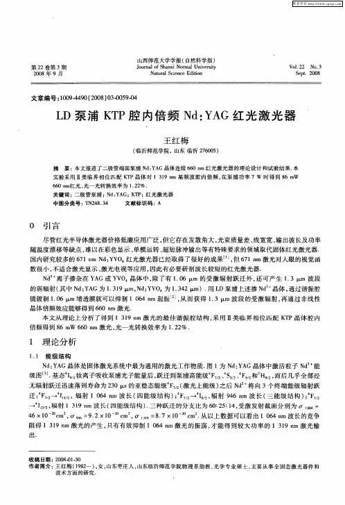
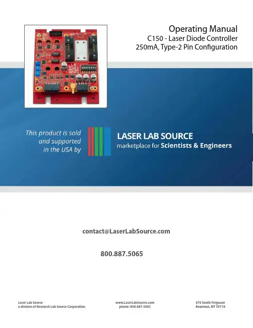
**************************800.887.5065Laser Lab Sourcea division of Research Lab Source Corporation phone: 800-887-5065670 South FergusonBozeman, MT 59718Operating ManualC150 - Laser Diode Controller 250mA, Type-2 Pin CongurationOperating manual Laser ControllerC150ContentsIntroduction (3)Absolute Maximum Ratings (4)Mechanical Information (4)Pin Layout (4)Electrical Characteristics (5)Power Connector J6 (7)Control and Monitor Connector J4 (7)Control and Monitor Connector J5 (SMB) (8)Test Connector J1 (8)DIP SwitchS1 (9)Status LED (10)Temperature Set Point (10)Temperature Measurements (10)PI Control (11)Integral heat sink (11)Power dissipation (11)External connections and cables (12)Installation (12)Certification (12)Warranty and returns (12)Return procedure (12)Revisions (12)IntroductionThe Laser Controller C150 combines an integrated temperature driver and laserdriver in one package. Temperature control is fully linear; a separate power supplycan be used for the laser TEC. TEC control can be via the built-in PI loop or anexternal signal. The laser driver has an analog bandwidth of 250 kHz; a separatefast TTL compatible switching is provided via a SMB connector. The laser currenthas a hardware limit of 250 mA which cannot be exceeded withoutcustomization.Features Laser Controller C150 provides full control for semiconductor laser including laser diode control and integrated temperature control.Applications Spectroscopy, Laser, Precision Instrument, OEM applicationsSpecifications Parameter ValuePower Dual Option 1: +12 V/2 A -12 V/0.5 AOption 2: +12V/0.5 A -12V/0.5A +5V /1.5ALaser Current ControlLaser current 0 - 250 mA. Hardware limit. Can be modified for customized versionsCompliance voltage > 4.0 VSetting accuracy 2 % fsNoise (RMS) < 2µADrift < 20 µATemperature coefficient 50 ppm/CCurrent limit 250 mASetting accuracy of current limit 2 % fsLaser External Control Voltage range 0 --> 10 VInput impedance 10 kOhmModulation coefficient ( I const ) 20 mA/V3dB Bandwidth DC … 250 kHzTTL modulation, rise / fall-time 250 nsInterlock YesTEC control TEC current 0 … +- 1.0 A /1.5ATEC voltage > 8.0 VMax output power 12 WCurrent limit 1A or 1.5 AInput sensor Thermistor 10 kOhm or 100 kOhm at 25 CPID control Internal PI control or External direct TEC currentcontrolConnectors Laser Integrated Azimuth Electronics 14 pin connectorwith heat sink. NEL DFB laser pinout. Can bereplaced with optional DB15 connector.Power Molex MicroFit 8 pin.Control Molex MicroFit 12 pin.Dimensions (WxHxD) 120 x 92 x 30 mmWeight 350 gStorage Temp -55 to 100 COperating Temp -40 to 85 CRedWave Labs Ltd keeps improving its products and therefore some specifications can vary.Absolute Maximum RatingsSymbol Parameter RatingsUnitV dd1Supply positive voltage / Laser driver and TEC +12±10% V V dd2Supply positive voltage / Separate TEC rail +5;+10%;-0% VV ee Supply negative voltage / Laser driver andTEC-12±10% VT op Operational Temperature -40 to 85 Deg CT st Storage Temperature -55 to 100 Deg CMechanical InformationParameter Value UnitLength 4.75 (120.65) Inch (mm)Width 3.65 (92.7) Inch (mm)Height 1.01 (25.1) Inch (mm)Weight 350 gramPin Layout1 TH+ 14 Not in use2 TH- 13 LD+3 Not in use 12 LD-4 Not in use 11 LD+5 Not in use 10 Not in use6 TEC+ 9 Not in use7 TEC- 8 Not in useTEMP SET P GAIN I GAIN PI GAIN TPElectrical CharacteristicsPower Connector J6Power connector J6 (pin assignment is on left) is Molex Micro-Fit p/n 43045-0800. Mating connector is Molex Micro-Fit p/n 43025-0800 with crimp pins Molex p/n 43030-0009. Mating connector and necessary number of crimp pins are included with C150 Laser controller. Molex suggested crimping tool p/n 63819-0000 which can be purchased from Digikey Inc ()Control and Monitor Connector J4Control and monitor connector J4(pin assignment is on left) is Molex Micro-Fit p/n 43045-1200. Mating connector is Molex Micro-Fit p/n 43025-1200 with crimp pins Molex p/n 43030-0009 . Mating connector and necessary number of crimp pins are included with C150 Laser controller. Molex suggested crimping tool p/n 63819-0000 which can be purchased from Digikey Inc ( )Control and Monitor Connector J5 (SMB)Laser On/Off connector J5 is standard SMB connector for easy direct connection of laser current fast ON/OFF signal.Test Connector J1Test connector J1 (pin assignment is on left) is Molex Milli-Grid p/n 87831-1620. Mating connector is Molex Milli-Grid p/n 87568-1694 for ribbon cable. C150 comes without Milli-Grid mating connector. Customized connector arrangement can be used for the remote control of the switch S1. RedWave Labs can advised on the specific applications when required.DIP SwitchS1S1 can be remotely controlled through J1 except for the TEC power selection (POSITION 8 in table below). This remote control functionality can be used for integration inside spectrometers or other instruments.Status LEDStatus LEDs are used for fast visual assessment of the C150 status. LEDs are located close to test connector J1. Default LED color is red; this can varied in customized versions.Temperature Set PointC150 has 2 options to control temperature set point. These options are:i) internal set point with the 11-turn potentiometer located on the opposite side of laser connector ; ii) external voltage applied to the Pin 7 of the J4 connector. Temperature MeasurementsLaser Controller C150 has two modes of temperature measurements. Temperature can be measured using the 10K or 100K thermistor. Selection between modes is made through switch S1-2. C150 uses a high stability voltage reference (V 0 = 5.00 V) on the board and measures the voltage across the thermistor using a bridge scheme. Thermistor voltage can be monitored between pins 11 and 12 of J1.Temperature can be derived from the voltage across the thermistor using the following formula:1/T = A + B * ln(R t ) + C * (ln(R t ))3R t = V t / (V 0 – V t ) * R 0Where R 0 = 10.0kOhm for the 10K thermistor and R 0=100K for the 100K thermistor. V t is the voltage across the thermistor. The 10 µA value of constants A, B and C (A= 1.1280e-03; B=2.3450e-04;C=8.73e-08) should be used to calculate thecorrect temperature. For example V t =2.500 V for T=25 C using 10K thermistor settings and using the 10K thermistor as the temperature measurement element.Note: This voltage is different from T set voltage (see above Temperature Set Point).PI ControlC150 has 2 options to control the temperature feedback loop: Internal and External. Internal PI control covers the vast majority of systems and the P and I control potentiometers can be adjusted to obtain the optimal PI. External PI control can be used if the user has a digital PID implementation elsewhere and connected to the Pin 3 of J4. Selection between internal and external control modes is done via S1-3.Proportional and Integral gains can be measured using 3 test points (Common ‘C’, Proportional ‘P’, and Integral ‘I’) just under of P and I potentiometers. The Proportional gain (A/V) can be calculated using the value of the resistance between ‘C’ and ‘P’ t est points and expressed in kOhm:mmprop R R G *+*−=98.142400where R m is the measured resistance.The Integral gain (A/(V*sec)) can be calculated using the same approach:min R G ++=15.45.0Integral heat sinkC150 has two options for the laser integrated heat sink (‘Low’ and ‘High’).‘Low’ heatsink is level with Printed circuit Board (PCB) and allows mount of customers’ designed laser package enclosure. Thi s option is used when an additional thermal isolation for DFB butterfly package is required.‘High’ heatsink is about 2.5 mm higher than PCB and typically used for direct mounting of butterfly packages. 2.5 mm elevation provides minimum stress for package pins.‘Low’ and ‘High’ option are easy interchangeable and relevant heat sinks can purchased independently.Power dissipationC150 laser controllers have been designed to 25 Watt power dissipation without heat sink at normal atmospheric conditions. 25 W dissipated heat is the maximum dissipated power. Most common regime would result in about 15 W heat dissipation. C150 does not require external heatsink.External connections and cablesC150 laser controller comes with mating connectors and crimp kit for J4 and J6. Cables for J1, J4 and J6 can be purchased separately.InstallationWe recommend a first time use of the C150 with a high power load resistor (at least 10W rating) as TEC load and Laser Diode load. These load should connected to the corresponding pins of J1. Such a set-up will enable a system check before connecting to the laser temperature controller system and risking potential damages.CertificationRedWave Labs Ltd certifies that: i) the parts and/or materials were produced in conformance with all contractually applicable Government and/or Buyer’s specification as referenced in, or furnished with, the above purchase order and ii) all processes required in the production of these parts and/or materials are listed and were performed by a facility or by personnel specifically approved or certified by the seller’s cognizant government quality control agency when such approval or certifi cation is required by an applicable specification. RedWave Labs products are not authorized for use in safety-critical applications (such as life support) where a failure of the product would reasonably be expected to cause severe personal injury or death, unless officers of the parties have executed an agreement specifically governing such use of the products.Warranty and returnsC150 Laser Controllers are warranted against defects in materials and workmanship for a period of 180 days from date of shipment. During the warranty period RedWave Labs Ltd will replace or repair products which prove to be defective or damaged. Our warranty shall not apply to defects or damages resulting from: i) misuse of the product or ii) operation beyond specifications detailed in the current manual.Return procedureCustomer must obtain a valid RMA number by contacting RedWave Labs prior to the return. In all cases the customer is responsible for duty fees incurred on all received shipments and on all international returns for both warranty and non-warranty items; the customer is responsible for any duties, brokers fees or freight charges deemed chargeable to RedWave Labs Ltd.RevisionsRevision 2: -Various changes in hardware to improve temperature stability.Revision 3: -Add 5 V power rail to decrease heat dissipation.-Changes for Connector J6-Corrected thermistor 10K/100K marking. Manual Rev 3.1-Added pinouts for laser diode. Manual Rev 3.1-Corrected TEC_I_MON transfer function. Manual Rev 3.1-Added information on LD_ON_OFF. Manual Rev 3.1。
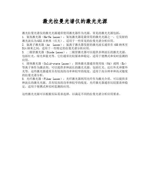
激光拉曼光谱仪的激光光源
激光拉曼光谱仪的激光光源通常使用激光器作为光源。
常见的激光光源包括:
1. 氦氖激光器(He-Ne Laser):氦氖激光器是最常用的激光光源之一,它发射的激光波长为63
2.8纳米(红光),适用于一些常见的拉曼光谱分析应用。
2. 氩离子激光器(Ar Laser):氩离子激光器发射的激光波长通常在488纳米至514纳米之间,适用于一些特定的拉曼光谱分析应用。
3. 二极管激光器(Diode Laser):二极管激光器可以提供多种波长的激光光源,包括红光、绿光和蓝光等。
它们通常比较紧凑和稳定,适用于便携式和实时监测的应用。
4. 固体激光器(Solid-state Laser):固体激光器通常使用钕(Nd)或铒(Er)等离子体作为激活剂,可以提供多种波长的激光光源,包括红光、近红外光和紫外光等。
这些激光器通常具有较高的功率和较窄的线宽,适用于高分辨率和高灵敏度的拉曼光谱分析。
5. 光纤激光器(Fiber Laser):光纤激光器利用光纤作为激光介质,可以提供多种波长的激光光源,具有较高的功率和较窄的线宽。
光纤激光器通常比较紧凑和稳定,适用于便携式和实时监测的应用。
这些激光光源可以根据实际需求选择,以满足不同的拉曼光谱分析应用要求。
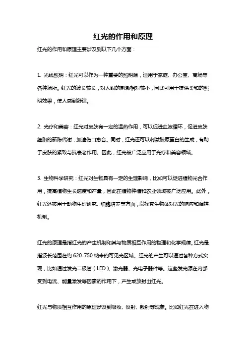
红光的作用和原理
红光的作用和原理主要涉及到以下几个方面:
1. 光线照明:红光可以作为一种重要的照明源,适用于家庭、办公室、商场等各种场所。
红光的波长较长,对人眼的刺激相对较小,因此可用于提供柔和的照明效果,使人感到舒适。
2. 光疗和美容:红光对皮肤有一定的温热作用,可以促进血液循环,促进皮肤细胞的新陈代谢,加速伤口愈合。
同时,红光还可以刺激胶原蛋白的生成,有助于皮肤的紧致与抗衰老作用。
因此,红光被广泛应用于光疗和美容领域。
3. 生物科学研究:红光对生物具有一定的生理影响,比如可以促进植物光合作用,提高植物生长速度和产量,因此在植物种植和农业领域被广泛应用。
此外,红光还被用于动物生理研究、细胞培养等方面,以探究生物体对光的响应和调控机制。
红光的原理是指红光的产生机制和其与物质相互作用的物理和化学规律。
红光是指波长范围在约620-750纳米的可见光区域。
红光的产生可以通过各种方式实现,比如通过发光二极管(LED)、激光器、光电子器件等。
这些发光源在内部受到电流、能量激发等因素的作用下,产生或放射出红光。
红光与物质相互作用的原理涉及到吸收、反射、散射等现象。
比如红光在进入物
体表面后,可以被物体的颜色成分吸收或反射,吸收后的能量可以转化为热能,从而产生温热效应。
此外,红光对不同物质的穿透性也不同,比如在皮肤组织中,红光可以较好地穿透到浅层组织,促进皮肤细胞的活化和修复。
总的来说,红光作为一种特定波长的可见光,具有较长的波长和较低的能量,其作用和原理在光照明、光疗和美容、生物科学研究等方面得到广泛应用。