高漫1060pro中文说明书
- 格式:pdf
- 大小:11.95 MB
- 文档页数:14

NXP Semiconductors Document identifier: MIMXRT10601064EKBHUG User's Guide Rev. 0, 06/2020MIMXRT1060/1064 Evaluation Kit Board Hardware User's GuideContentsChapter 1 Introduction (3)1.1 Board overview (3)1.2 MIMXRT1060/1064 EVK contents (4)1.3 MIMXRT1060/1064 EVK board revision history (4)Chapter 2 Specifications (5)2.1 i.MX RT1060/1064 processor (7)2.2 Boot mode configurations (7)2.3 Power tree (8)2.4 SDRAM memory (11)2.5 SD card slot (11)2.6 Hyper flash (11)2.7 QSPI flash (11)2.8 Ethernet connector (12)2.9 USB PHY connector (12)2.10 Audio input/output connector (12)2.11 OpenSDA circuit (DAP-Link) (12)2.12 JTAG connector (12)2.13 Arduino expansion port (13)2.14 Camera module connector (14)2.15 User interface switch (14)2.16 Sensor (15)2.17 User interface LED indicator (15)2.18 LCD interface (15)Chapter 3 PCB information (16)Chapter 4 EVK design files (17)Chapter 5 EVK contents (18)Chapter 1IntroductionThis document describes MIMXRT1060/1064 Evaluation Kit (EVK) based on the i.MX RT1060/1064 processor from NXP Semiconductor. The document includes system setup, debugging, and provides detailed information on the overall design and usage of the EVK board from a hardware system.1.1Board overviewThis EVK board is a platform designed to showcase the commonly used features of the i.MX RT1060/1064 Processor in a small, low-cost package. The MIMXRT1060/1064 EVK board is an entry level development board that familiarizes the developer to the processor before investing on resources for specific designs.The features of the MIMXRT1060/1064 EVK board are listed in Board features.The features of the MIMXRT1060/1064 EVK board are listed in Table 1.Table 1.Board featuresProcessor NXP Processor MIMXRT1062DVL6AMIMXRT1064DVL6ADRAM Memory SDRAM 256 Mbit, 166 MHz IS42S16160J-6BLIDCDC MPS MP2144GJLDO UNION UM1550S-18UM1750S-00Mass Storage TF Card Slot64 Mbit Quad SPI flash512 Mbit Hyper flashDisplay Interface LCD connectorEthernet10/100 Mbit/s Ethernet connector. PHY chip: KSZ8081RNBUSB USB 2.0 OTG connectorUSB 2.0 host connectorAudio Connector 3.5 mm audio stereo headphone jackBoard-mounted microphoneLeft and right speaker out connectorsS/PDIF interface (unpopulated )Power Connector 5 V DC-jackDebug Connector JTAG 20-pin connector (SWD by default)OpenSDA with DAP-LinkSensor FXOS8700CQ: 6-Axis Ecompass (3-Axis Mag, 3-Axis Accel)(Some boards are unpopulated)Table continues on the next page...IntroductionTable 1.Board features (continued)Camera CMOS sensor interfaceCAN CAN bus connectorUser Interface Button ON/OFF, POR Reset, Reset, USER buttonLED Indicator Power Status, Reset, OpenSDA, USER LEDExpansion Port Arduino interfacePCB 3.937 inch x 5.9055 inch (10 cm x 15 cm), 4-layer board1.2MIMXRT1060/1064 EVK contentsThe MIMXRT1060/1064 EVK contains the following items:•MIMXRT1060/1064 EVK board•USB cable (Micro B)•Camera1.3MIMXRT1060/1064 EVK board revision historyEVK: Mass ProductChapter 2SpecificationsThis section provides detailed information about the electrical design and practical considerations of the EVK board. The document describes each block shown in Block diagram.The document describes each block shown in Figure 1.Figure 1.Block diagramThe overview of the MIMXRT1060 EVK board is shown in Figure 2 and Figure 3.Figure 2.Overview of the MIMXRT1060 EVK board (Front side)Figure 3.Overview of the MIMXRT1060 EVK board (Back side)2.1i.MX RT1060/1064 processorThe i.MX RT1060/1064 is a new processor family featuring NXP advanced implementation of the Arm Cortex-M7 Core. It provides high CPU performance and best real-time response. i.MX RT1060/1064 provides various memory interfaces, including SDRAM, Raw NAND flash, NOR flash, SD/eMMC, Quad SPI, HyperBus, and a wide range of other interfaces for connecting peripherals, such as WLAN, Bluetooth™, GPS, displays, and camera sensors. i.MX RT1060/1064 has rich audio and video features, including LCD display, basic 2D graphics, camera interface, S/PDIF, and I2S audio interface.The i.MX RT1060/1064 applications processor can be used in areas such as industrial HMI, IoT, motor control, and home appliances. The flexibility of the architecture enables it to be used in a wide variety of other general embedded applications too. The i.MX RT processor provides all interfaces necessary to connect peripherals such as WLAN, Bluetooth™, GPS, camera sensors, and multiple displays.The more detail information about i.MX RT1060/1064 can be found in the Datasheet and Reference Manual.2.2Boot mode configurationsThe device has four boot modes (one is reserved for NXP use). The boot mode is selected based on the binary value stored in the internal BOOT_MODE register.Switch (SW7-3 and SW7-4) is used to select the boot mode on the MIMXRT1060/1064 EVK board.Table 2.Boot mode pin settingsBOOT_MODE[1:0] (SW7-3 SW7-4)BOOT TypeTable continues on the next page...Table 2.Boot mode pin settings (continued)00Boot From Fuses 01Serial Downloader 10Internal Boot 11ReservedTypically, the internal boot is selected for normal boot, which is configured by external BOOT_CFG GPIOs. Table 3 shows the typical Boot Mode and Boot Device settings.Table 3.Typical boot mode and boot device settings for RT1060SW7-1SW7-2SW7-3SW7-4Boot Device OFF ON ON OFF Hyper flash OFFOFF ON OFF QSPI flash ONOFFONOFFSD cardFor more information about boot mode configuration, see the System Boot chapter of the MIMXRT1060 Reference Manual .For more information about MIMXRT1060 EVK boot device selection and configuration, see the main board schematic .Table 4.Typical boot mode and boot device settings for RT1064SW7-1SW7-2SW7-3SW7-4Boot Device OFF OFF ON OFF QSPI flash ONOFFONOFFSD card2.3Power treeA DC 5 V external power supply is used to supply the MIMXRT1060/1064 EVK board at J2, and a slide switch SW1 is used to turn the Power ON/OFF. J41 and J9 is used to supply the EVK board.Table 5 lists different J1 jumper settings for different power supply.Table 5.Jumper settings for power supply Power Supply J1 Setting J21-2J93-4J415-6The power tree is shown in the following figure.Figure 4.Power treeThe power control logic of the MIMXRT1060/1064 EVK board is shown in the Figure 5.•SNVS is powered first and then PMIC_REQ_ON is switched on to enable external DC/DC to power up other power domains.•ON/OFF button is used to switch ON/OFF PMIC_REQ_ON to control power modes.•RESET button and WDOG output are used to reset the system power.Figure 5.Power control diagramThe power rails on the board are shown in Table 6.Table 6.Power railsTable continues on the next page...Table 6.Power rails (continued)2.4SDRAM memory256 Mbit, 166 MHz SDRAM (IS42S16160J-6BLI) is used on the EVK board.2.5SD card slotThere is an SD card slot (J39) on the MIMXRT1060/1064 EVK board. J39 is the Micro SD slot for USDHC1 interface. To boot from the SD card, the boot device switch (SW7) settings should be: ON, OFF, ON, OFF, as shown in Typical boot mode and boot device settings.2.6Hyper flashOn the MIMXRT1060/1064 EVK board, there is one 512 Mbit hyper flash device. To boot from the Hyper Flash, the boot device switch (SW7) settings should be: OFF, ON, ON, OFF, as shown in Table 3. By default, this hyper flash is disabled on the EVK. To enable the onboard hyper flash, update the following settings.1.Weld resistors: R356, R361 - R366.2.Removed 0Ωresistors: R153 - R158.The boot from hyper flash only supports RT1060.2.7QSPI flashA 64 Mbit QSPI flash is used on the MIMXRT1060/1064 EVK board. If the developer wants to boot from the QSPI flash, the boot device switch (SW7) settings should be: OFF, OFF, ON, OFF, as shown in Table 3. The QSPI flash is the default onboard flash.The boot from QSPI flash only supports RT1060.2.8Ethernet connectorThere are two Ethernet Mac controllers in the MIMXRT1060/1064 processor. The Ethernet subsystem of the MIMXRT1060/1064 EVK board is provided by the KSZ8081RNB 10/100 M Ethernet Transceiver (U16) and an RJ45 (J19) with integrated magnetic.2.9USB PHY connectorMIMXRT1060/1064 contains two integrated USB 2.0 PHYs capable of connecting USB host/device systems at:•USB low-speed (LS) rate of 1.5 Mbits/s•USB full-speed (FS) rate of 12 Mbits/s•USB 2.0 high-speed (HS) rate of 480 Mbits/s2.10Audio input/output connectorThe audio codec used on the MIMXRT1060/1064 EVK board is Wolfson’s low power, high-quality stereo codec, WM8960. The MIMXRT1060/1064 EVK board includes:•one headphone interface (J12)•one onboard MIC (P1)•two speaker interfaces (J16, J17)•S/PDIF interface (J14 and J18, DNP).J12 is a 3.5 mm audio-stereo headphone jack, which supports jack detect.2.11OpenSDA circuit (DAP-Link)The OpenSDA circuit (CMSIS–DAP) is an open-standard serial and debug adapter. It bridges serial and debug communications between a USB host and an embedded target processor.CMSIS-DAP features a mass storage device (MSD) bootloader, which provides a quick and easy mechanism for loading different CMSIS-DAP applications such as flash programmers, run-control debug interfaces, serial-to-USB converters, and more.Two or more CMSIS-DAP applications can run simultaneously. For example, run-control debug application and serial-to-USB converter run in parallel to provide a virtual COM communication interface while allowing code debugging via CMSIS-DAP with single USB connection.For the MIMXRT1060/1064 EVK board, J41 is the connector between the USB host and the RT1060/1064. To update the Open SDA firmaware, press the SW8 and Power on the board. There is a disk named "MAINTENANCE". Drag/drop the new firmware to the "MAINTENANCE" and re-power the board. The firmware is updated.2.12JTAG connectorJ21 is a standard 20-pin/2.54 mm box header connector JTAG. The pin definitions are shown in Figure 6. It supports SWD by default.Figure 6.JTAG pin definitions2.13Arduino expansion portJ22 – J25 is defined as Arduino interface. Table 7 lists the pin definitions of Arduino interface. Table 7.Arduino Interface pin definitionsJ22J23UART_RX/D0A0/ADC0UART_TX/D1A1/ADC1D2/INT0A2/ADC2D3/INT1/PWM/OC2B A3/ADC3D4/T0/XCK A4/ADC4/SDAD5/TI/PWM A5/ADC5/SCLD6/AIN0/PWM/OC0AD7/AIN1/PWMJ24J25D8/CLKO/ICP1NCD9/OC1A/PWM IOREFD10/SPI_CS RESETD11/OC2A/PWM/SPI_MOSI 3.3 VD12/SPI_MISO 5 VD13/SPI_CLK GNDGND GNDAREFD14/I2C_SDAD15/I2C_SCL2.14Camera module connectori.MX RT1060/1064 supports one parallel CSI (Camera Sensor Interface). There is a camera module connector (J35) on the MIMXRT1060/1064 EVK board. The CA031C based on OV7725 and CA111C based on MT9M114 are used directly.J35 supports both MT9M114 and OV7725 camera module, but 3.3 V is a violation to MT9M114 spec 3.1 V. Itproved fine for evaluation/demo with 3.3 V supply, but in product design, it is recommended to adjust DCDC outputor add level shifter.2.15User interface switchThere are four user interface switches on the MIMXRT1060/1064 EVK board.•Power switch•ON/OFF button•Reset button•USER button2.15.1Power switchSW1 is a slide switch to control the power of the MIMXRT1060/1064 EVK board when the power supply is from J2.•Sliding the switch to the ON position connects the 5 V power supply to the evaluation board main power system.•Sliding the switch to the OFF position immediately removes all power from the board.2.15.2ON/OFF buttonSW2 is the ON/OFF button for MIMXRT1060/1064 EVK board. A short pressing in OFF mode causes the internal power management state machine to change state to ON. In ON mode, a short pressing generates an interrupt as a software-controllable power-down. An approximate 5 seconds or more pressing causes a forced OFF. However, you can disconnect both the boot mode inputs.2.15.3Reset buttonThere are two Reset buttons on the EVK board. SW3 is the power-on reset button. Pressing SW3 in the power on state forces to reset the system power except SNVS domain. The processor immediately turns off and reinitiates a boot cycle from the processor power off state. SW9 is a reset button.2.15.4USER buttonSW8 is a USER button (GPIO5-00). Pressing the USER button can produce changes in high and low levels.2.16SensorU32 on the EVK board is a 6-Axis Ecompass (3-Axis Mag, 3-Axis Accel) sensor FXOS8700CQ. The Ecompass is connected to i.MX RT1060/1064 I2C1 port.The sensor is not populated on some boards.2.17User interface LED indicatorThere are four LED status indicators on the EVK board.The functions of these LEDs include:•Main Power Supply (D3)—Green: DC 5 V main supply is normal.—Red: J2 input voltage is over 5.6 V.—Off: Board is not powered.•Reset RED LED (D21)•OpenSDA LED (D20)•USER LED (D18)2.18LCD interfaceThe enhanced Liquid Crystal Display Interface (eLCDIF) is a general-purpose display controller.The eLCDIF block supports the following:•Displays that support moving pictures and require the RGB interface mode (DOTCLK interface).The eLCDIF provides fully programmable functionality to supported interfaces:•Bus master interface to source frame buffer data for display refresh.•8/16/18/24/32 bit LCD data bus support available depending on I/O MUX options.•Programmable timing and parameters for DOTCLK LCD interfaces.To use the LCD, NXP provides an optional LCD module RK043FN02H-CT. RK043FN02H-CT has a 4.3 inches touch screen and supports a resolution of up to 480*3(RGB)*272. This module contains two FPC cables. The LCD interface is connected to J8 (A1-A40) and the CPT interface can be connected to J8 (B1-B6). You can purchase LCD modules from .PCB informationThe MIMXRT1060/1064 EVK board is uses the standard 4-layer technology. The material used is FR-4. The PCB stack-up information is shown in Table 8.Table 8.Board stack-up informationEVK design filesYou can download, the schematics, layout files, and gerber files (including Silkscreen) from /MIMXRT1060-EVK.EVK contentsThe following table lists the contents on the evaluation kit.Table 9.EVK contentsItem DescriptionEVK board EVK board with processor, memory, interfaces and so on. USB cable USB cable (Micro-B to Standard-A).Camera CA111C based on MT9M114.Power adapter, micro-SD card, and LCD module are not standard parts of the evaluation kit.How To Reach Us Home Page: Web Support: /support Information in this document is provided solely to enable system and software implementers to use NXP products. There are no express or implied copyright licenses granted hereunder to design or fabricate any integrated circuits based on the information in this document. NXP reserves the right to make changes without further notice to any products herein.NXP makes no warranty, representation, or guarantee regarding the suitability of its products for any particular purpose, nor does NXP assume any liability arising out of the application or use of any product or circuit, and specifically disclaims any and all liability, including without limitation consequential or incidental damages. “Typical” parameters that may be provided in NXP data sheets and/or specifications can and do vary in different applications, and actual performance may vary over time. All operating parameters, including “typicals,” must be validated for each customer application by customer's technical experts. NXP does not convey any license under its patent rights nor the rights of others. NXP sells products pursuant to standard terms and conditions of sale, which can be found at the following address: / SalesTermsandConditions.While NXP has implemented advanced security features, all products may be subject to unidentified vulnerabilities. Customers are responsible for the design and operation of their applications and products to reduce the effect of these vulnerabilities on customer’s applications and products, and NXP accepts no liability for any vulnerability that is discovered. Customers should implement appropriate design and operating safeguards to minimize the risks associated with their applications and products.NXP, the NXP logo, NXP SECURE CONNECTIONS FOR A SMARTER WORLD, COOLFLUX, EMBRACE, GREENCHIP, HITAG, I2C BUS, ICODE, JCOP, LIFE VIBES, MIFARE, MIFARE CLASSIC, MIFARE DESFire, MIFARE PLUS, MIFARE FLEX, MANTIS, MIFARE ULTRALIGHT, MIFARE4MOBILE, MIGLO, NTAG, ROADLINK, SMARTLX, SMARTMX, STARPLUG, TOPFET, TRENCHMOS, UCODE, Freescale, the Freescale logo, AltiVec, C‑5, CodeTEST, CodeWarrior, ColdFire, ColdFire+, C‑Ware, the Energy Efficient Solutions logo, Kinetis, Layerscape, MagniV, mobileGT, PEG, PowerQUICC, Processor Expert, QorIQ, QorIQ Qonverge, Ready Play, SafeAssure, the SafeAssure logo, StarCore, Symphony, VortiQa, Vybrid, Airfast, BeeKit, BeeStack, CoreNet, Flexis, MXC, Platform in a Package, QUICC Engine, SMARTMOS, Tower, TurboLink, and UMEMS are trademarks of NXP B.V. All other product or service names are the property of their respective owners. AMBA, Arm, Arm7, Arm7TDMI, Arm9, Arm11, Artisan, big.LITTLE, Cordio, CoreLink, CoreSight, Cortex, DesignStart, DynamIQ, Jazelle, Keil, Mali, Mbed, Mbed Enabled, NEON, POP, RealView, SecurCore, Socrates, Thumb, TrustZone, ULINK, ULINK2, ULINK-ME, ULINK-PLUS, ULINKpro, µVision, Versatile are trademarks or registered trademarks of Arm Limited (or its subsidiaries) in the US and/or elsewhere. The related technology may be protected by any or all of patents, copyrights, designs and trade secrets. All rights reserved. Oracle and Java are registered trademarks of Oracle and/or its affiliates. The Power Architecture and word marks and the Power and logos and related marks are trademarks and service marks licensed by .© NXP B.V. 2020.All rights reserved.For more information, please visit: Forsalesofficeaddresses,pleasesendanemailto:**********************Date of release: 06/2020Document identifier: MIMXRT10601064EKBHUG。
MX HomePro MXHP-R700 Owner’s Manual© 2018 Universal Remote Control Inc. all rights reserved.The information in this manual is copyright protected. No part of this manual may be copied or reproduced in any form without prior written consent fromUniversal Remote Control.Universal Remote Control SHALL NOT BE LIABLE FOR OPERATIONAL, TECHNICAL, OR EDITORIAL ERRORS/OMISSIONS MADE IN THIS MANUAL. The information in this manual is subject to change without prior notice.MXHP-R700 Owner’s Manual © 2018 Universal Remote Control, Inc. URC - Control the Experience is a registered trademark of Universal Remote Control, Inc.Table of ContentsCongratulations (1)Features and Benefits.......................................................................................................1Parts List.............................................................................................................................1Before Getting Started......................................................................................................2Connecting the Lithium Polymer Battery......................................................................2Using the Charging Cradle...............................................................................................2Using the MXHP-R700.......................................................................................................3Displaying the Settings....................................................................................................4Settings Menu.. (5)MX HomePro Editor (13)Specifications (13)Limited Warranty Statement (13)End User Agreement (13)Congratulations!Thank you for purchasing the MXHP-R700 Wi-Fi based remote for your MX HomePro system. This remote offers real-time two-way feedback on compatible smart devices throughout the home or small office space. Controlling and monitoring the home’s devices is as simple as a click on the remote.Features and Benefits:The MX HomePro remote is designed to be the perfect companion to any TV room or bedroom night table. Enjoy the following features:●Quick Connect Wi-FiWhen picked up, the remote automatically connects to Wi-Fi within moments to control the home’s audio/video system and devices.●Two-way Meta-data Feedback:Experience real-time two-way feedback right on the remote’s LCD screen when used with compatible Z-Wave smart devices. Enjoy this same feedback when used with URC’s ever expanding list of 3rd party products.●Button LED Backlighting:Use your remote with ease regardless of lighting conditions thanks to the MXHP-R700’s LED button backlighting.●Pick-Up Sensor:Lifting the remote immediately wakes it up and turns on the LCD screen. It quickly connects to Wi-Fi allowing the user to control their MX HomePro system instantly.●Rechargeable Lithium Polymer Battery:Parts List:Included in the MXHP-R700 box:●MXHP-R700 Wi-Fi Remote●AC Power Adapter●Rechargeable Lithium Polymer Battery●Charging CradleBefore Getting Started:Prior to installing an MX HomePro system, there are a few things to remember:●MX HomePro systems are designed for use on the home’s local network .The hub can be connected to the home network through an Ethernet cable or wirelessly via Wi-Fi.●Adding a TRF-ZW Z-Wave Gateway gives the MX HomePro system access to control the home’s Z-Wave devices such as locks, thermostats, lighting,cameras, and scenes.●Programming is performed via the MX HomePro Editor . The smart home professional must log into this web portal in order to program all applicable MX HomePro devices. Further enhancements may be added, for all inquires please contact URC Technical Support .●This remote communicates exclusively through 2.4 GHz Wi-Fi usingb/g/n signals.Connecting the Lithium Polymer Battery:When getting ready to add the remote to the system or replacing a battery, perform the following steps:1. Press the spring lock down to open the remote cover.2. Place the battery (included) into the compartment making sure to align the contacts on the battery and the remote.3.Replace the ing the Charging Cradle:Connect the 6V DC adapter into the power outlet and into the rear of the charging cradle (also connects to the remote for direct charging). Gently place the MXHP-R700 remote into the cradle. The remote automatically aligns itself to the contacts on the charging base. The status light immediately illuminates:●Red indicates that the remote is charging.●Blueindicates the remote is fully charged.Using the MXHP-R700 (Remote):The Home menu pages display all the programmed activities and devices within the MX HomePro system.To navigate to this, simply press the Home button and use the Up and Down buttons to move throughout the menu.Press any button adjacent to the screen to select an activity or device. Press the Homebutton to return to the previous page and select a new device or activity.The Volume and Mute buttons are alwaysavailable regardless of what screen is displayed.The Home button always displays the Home Menupages.The Up and Down buttons areused to navigate through amenu screen.Displaying the Settings:Entering the Settings Menu is accomplished by pressing and holding the Home and Enter (ENT) buttons simultaneously for three (3) seconds.Use the Up and Down buttons to navigate between items on the Settings Menu. To select, press the button on the side of the LCD screen or the Select (SEL) button when the item is highlighted.Shown below is an expanded view of the MXHP-R700’s Settings Menu, not all options on this image are available on the screen at once.Settings Menu:The following sections cover the sub-menus found within the Settings Menu: Network Settings:This menu displays the network information about the MXHP-R700 and the network it is connected to.From this screen, it is possible to scan for different Wi-Fi networks, select a network to connect to, and enter any custom settings.Base Station (Hub) Setup:This menu displays all of the hubs that are currently connected to the network.Remember, hubs are identified by their Wired MAC Address.This can be found on the underside of a hub (refer to MX HomePro MXHP-H500Owner’s manual).TRF-ZW Z-Wave Accessory Account Info:When using smart home devices that use Z-Wave, it is necessary to log the Accessory Account info onto the remote (see MX HomePro Installation Guide). The Accessory Account info item allows the entry of a URC TRF-ZW account username and password.The screens displayed at the right show how this looks when the Accessory Account information has been entered and verified.Contact your smartinstaller to acquire Z-Wave home lighting,comfort, and security products for use withyour MX HomePro system.Sleep Timer:This setting item allows the user to adjust the amount of time the LCD remains On when not in use.The time can be set independently based on whether the remote is using battery power or is connected to the charger.Selecting an item on this screen allows for the settings of each Sleep Timer value.Once the Sleep Timers are adjusted, press Save . The Go Back button returns the remote’s to the Setup Menu and preserves the last saved setting.Brightness:This item allows the user to adjust the brightness of the LCD screen’s e the “-” and “+” buttons to decrease or increase the LCD’s brightness.Once complete, press Save . Pressing Go Back button returns to the remote’s last saved setting.Button Light:Adjust the brightness of the LEDs that backlight the buttons of the MXHP-R700.Adjust the button light brightness by using the “-” and “+” buttons to do so.Once adjusted, press Save . Pressing Go back reverts to the remote’s lastsaved setting.System:This menu displays data about the remote’s operating system, memory, and other information.Press the More button to view further system information or press Go Back to exitto the previous menu.Power:Displays the remaining battery level of the remote.The low battery warning message can be adjusted from this section. Adjust the battery percentage using the “-” and “+” buttons to do so.Once adjusted, press Save . Pressing Go back reverts to the remote’s last saved setting.Sound:Through this menu, adjusting the sound on button presses can be changed.Press the adjacent hard buttons to increase or decrease the button volume.Once adjusted, press the Save button. Pressing the Go Back button returns to the remote’s last saved setting.Pickup:This menu allows the user to adjust the sensitivity of the remote when reacting to being picked up.Increase or decrease the sensitivity using the “-” and “+” buttons.Once adjusted, press the Save button. Pressing the Go Back button returns to the remote’s last saved settingFirmware Update:Selecting this makes the remote search for any available firmware update. When available, the screen displays as seen on the right. Select Yes to begin the updating the remote’s firmware. Select No to return to the previous menu.When the firmware updates successfully, this screen is displayed as confirmation.Factory Default:Warning!Selecting this options returns the MXHP-R700 to its factory default settings. All programming is lost and the system requires re-programming.Select Yes starts the factory reset process. This should only be done wheninstructed by URC Technical Support or by the smart home professional installer.Selecting No returns the user to the previous screen.Exit:When completed with adjusting any user settings, select Exit to return the remote to normal operation.MX HomePro Editor:To begin programming the system, log into the MX HomePro Editor via:See the MX HomePro Programming Guide for more details.Specifications:LCD: 2 inch screen (240 x 320) LCD Backlighting by LEDDevices: Supports up to 255 devices with text, less with heavy graphics Macro Capability: Up to 255 steps each; however, nesting is allowed Wi-Fi: IEEE 802.11 b/g/nBattery: Lithium polymer 1,960mAhBattery Charging Time: 5 hoursSize: 8.46” H x 2.04” W x 1.02” DBattery Warranty: 90 days Limited Warranty Statement Click on the section title above to read the full terms and conditions of the Limited Warranty Statement. Also available publicly on the URC home page.End User Agreement Click on the section title above to read the full terms and conditions of theEnd User Agreement. Also available publicly on the URC home page.Federal Communication Commission Interference Statement:This equipment has been tested and found to comply with the limits for a Class B digital device, pursuant to part 15 of the FCC Rules. These limits are designed to provide reasonable protection against harmful interference in a residential installation. This equipment generates, uses and can radiate radio frequency energy and, if not installed and used in accordance with the instructions, may cause harmful interference to radio communications. However, there is no guarantee that interference will not occur in a particular installation. If this equipment does cause harmful interference to radio ortelevision reception, which can be determined by turning the equipment off and on, the user is encouraged to try to correct the interference by one more of the following measures:●Reorient or relocate the receiving antenna.●Increase the separation between the equipment and receiver.●Connect the equipment into an outlet on a circuit different from that to which the receiver is connected.●Consult the dealer or an experienced radio/TV technical for help.Warning!Changes or modifications not expressly approved by the manufacturer could void the user's authority to operate the equipment.The manufacturer is not responsible for any Radio or TV interference caused by unauthorized modifications to this equipment. Such modifications could void the user's authority to operate the equipment.FCC Caution:This device complies with Part 15 of the FCC Rules. Operation is subject to the following two conditions:1. This device may not cause harmful interference.2. This device must accept any interference received, including interference thatmay cause undesired operation. Any changes or modifications not expresslyapproved by the party responsible for compliance could void the authority tooperate equipment. The antenna(s) used for this transmitter must not be co-located or operating in conjunction with any other antenna or transmitter. Federal Communication Commissions (FCC)Radiation Exposure Statement:This remote device is approved as a hand-held and hand-operated only portable (relative to hand) device, which is normally operated at 5cm from a person’s body.。
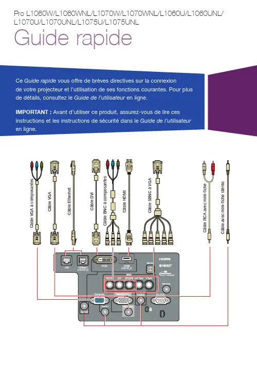
Alterner entre les sources d’imageAppuyez sur la touche Search ou sur l’une des touches de source (télécommande), ou appuyez sur la touche Source Search (projecteur).Sélectionner le type d’objectifAssurez-vous que le paramètre Type d’objectif correspond à l’objectif que vous utilisez.1. A ppuyez sur la touche Menu .2. S électionnez Avancé >Fonctionnement > Avancé > Type d’objectif .R emarque : Si le paramètre de Type d’objectif est grisé, cela signifie que le projecteur a automatiquement détecté l’objectif installé et vous pouvez passer les étapes restantes.3. S électionnez l’objectif que vousutilisez.4. L orsque vous avez terminé, appuyezsur la touche Menu pour quitter.Modifier le format d’écranRéglez le paramètre de format d’écran selon le rapport hauteur/largeur de l’écran que vous utilisez. 1. A ppuyez sur la touche Menu .2. S électionnez Avancé > Affichage >Réglages Écran > Format d’écran .Allumer le projecteur1. M ettez l’ordinateur ou la sourced’image sous tension.2. R etirez le couvre-objectif.3. A ppuyez sur la touche Ond’alimentation du projecteur ou de la télécommande. Lorsque le témoin d’état reste bleu, le projecteur est prêt à être utilisé.R emarque : Si la fonction Aliment.Directe est activée, vous pouvez mettre le projecteur sous tension sans appuyer sur la touche On d’alimentation; vous pouvez le brancher ou actionner l’interrupteur contrôlant la prise de courant à laquelle le projecteur estbranché. Pour activer cette fonctionnalité, consultez le Guide de l’utilisateur en ligne.4. S i votre image ne s’affiche pas,consultez la section « Alterner entre les sources d’image » ou « Dépannage ».Modifier la langue des menus du projecteurLa langue par défaut du projecteur est l’anglais, mais vous pouvez modifier la langue si vous le désirez.1. A ppuyez sur la touche Menu pouraccéder au système des menus.2. S électionnez Extended >Language .3. S électionnez votre langue.4. L orsque vous avez terminé, appuyezsur la touche Menupour quitter.Ajuster la mise au point et le zoom1. S ur la télécommande, appuyez surla touche Zoom ou Focus.S ur le projecteur, appuyez sur latouche Lens à plusieurs reprises jusqu’à ce que l’écran d’ajustement de zoom ou de mise au point s’affiche.2. A ppuyez sur les touches fléchéesou afin d’effectuer l’ajustement. 3. A ppuyez sur la touche Esc afin decompléter l’ajustement.Corriger la forme de l’imageSi les bords de votre image ne sont pas égaux, vous pouvez utiliser les fonctionnalités de correction de la distorsion du projecteur telles que H/V-Keystone et Quick Corner ® pour régler la forme. Consultez le Guide de l’utilisateur en ligne.3. S électionnez le rapport hauteur/largeur de l’écran.R emarque : L’image affichée devrait correspondre à la taille et à la forme de l’écran.4. L orsque vous avez terminé, appuyezsur la touche Menu pour quitter.R emarque :Après avoir modifié le format d’écran, il est possible que vous deviezmodifier le rapport hauteur/largeur de l’image projetée selon le signal d’entrée. Appuyez sur la touche Aspect de la télécommande pour modifier le rapport hauteur/largeur, au besoin.Ajuster la position de l’image1. A ppuyez sur la touche Lens Shift(télécommande) ou sur la touche Lens (projecteur).2. A ppuyez sur les touches fléchéespour ajuster la position de l’image projetée.3. L orsque vous avez terminé, appuyezsur la touche Esc pour compléter l’ajustement.Si le projecteur est placé sur une table, vous pouvez ajuster le niveau de l’image en tournant l’une des pattes arrière réglables du projecteur.Effectuer d’autres réglages de l’imagePour obtenir de l’aide concernantl’utilisation des fonctionnalités du projecteur afin d’améliorer la qualitéde l’image, consultez le Guide del’utilisateur en ligne. Vous pouvez aussi consulter de l’information sur la façon de régler les couleurs, la position et les bordures (harmonisation des bordures) de l’image lorsque vous utilisez plusieurs projecteurs pour créer une image continue de format large.Éteindre le projecteurAppuyez sur la touche Standby pour mettre le projecteur hors tension. Siun message de confirmation s’affiche, appuyez de nouveau sur la touche Standby.Remarque : Si la fonction Aliment. Directe est activée, vous pouvez débrancherle projecteur ou actionner l’interrupteur contrôlant la prise de courant à laquellele projecteur est branché. Pour activercette fonctionnalité, consultez le Guide de l’utilisateur en ligne.Avec la technologie Instant Off®d’Epson, vous n’avez pas besoind’attendre le refroidissement du projecteur. Vous pouvez simplement le mettre hors tension et le débrancher lorsque vous avez terminé.DépannageL’écran est vide ou le message Aucun signal s’affiche :• A ssurez-vous que le témoin d’état du projecteur est bleu, qu’il neclignote pas et vérifiez que lecouvre-objectif est ouvert.• A ssurez-vous que les câbles sont branchés correctement. Consultez le Guide de l’utilisateur en ligne.• I l est possible que vous deviez modifier la source d’image.Consultez la section « Alterner entreles sources d’image ». Assurez-vous aussi que le dispositif de la sourced’image est sous tension.Le projecteur et l’ordinateur portable n’affichent pas la même image : Windows®Appuyez sur la touche de fonctionde votre clavier qui permet d’afficher sur un moniteur externe. Cette touche peut être étiquetée CRT/LCD ou peut être identifiée par une icône comme . Il est possible que vous deviez maintenir la touche Fn du clavier de votre ordinateur portable enfoncée aumême moment (comme Fn + F7). Vous devez attendre quelques instants pour que l’image s’affiche. Il est possible que vous deviez appuyer sur les touches de nouveau afin d’afficher l’image sur les deux appareils.Pour Windows 7 ou une versionultérieure, maintenez la touche Windows enfoncée et appuyez sur P en même temps, puis cliquez sur Dupliquer. MacOuvrez Préférences Système etsélectionnez Moniteurs. Cliquez surl’onglet Disposition et cochez la case Recopie vidéo.Allume le projecteur Illumine les touches de façon temporaireRègle automatiquement l’imagede l’ordinateurModifie le rapport hauteur/largeurOuvre les menus désignéspar l’utilisateur Agrandit ou rapetisse une partie de l’imageCorrige la forme de l’image Enregistre et applique les présélectionsPort pour la connexion du câblede la télécommandeCommande un ou plusieursprojecteursMaintenez enfoncé et utilisez les touches numériques pour sélectionner le projecteur àcommander Maintenez enfoncé et utilisez les touches numériques pour entrer des chiffresSélectionne un des modes couleursÉteint le projecteurSélectionne une sourcePermet de naviguer à travers les paramètres des menus;déplace le pointeurAffiche un motif de test Règle la position de l’image Ouvre les menus du projecteur Sélectionne les paramètres du menu; bouton de souris gaucheDésactive temporairementl’affichage et le son Passe à l’image suivante ou précédente lorsque vous projetez depuis un ordinateursur un réseauCommande le volume Arrête la fonction en cours ou retourne au menu précédent; bouton de souris droit Affiche le menu Information Permet de basculer entre les sources d’imagePermet de figer l’image Divise l’écran entre deux entréesRègle la mise au point Modifie la taille de l’imageRéinitialise les paramètres du menu à leurs valeurs par défaut Accède à l’écran d’accueilFonctions de la télécommandeEPSON, Instant Off et Quick Corner sont des marques déposées et EPSON Exceed Your Vision est un logotype déposé de Seiko Epson Corporation.PrivateLine est une marque déposée d’Epson America, Inc.Mac est une marque de commerce d’Apple Inc., déposée aux États-Unis et dans d’autres pays.Windows est une marque déposée de Microsoft Corporation aux États-Unis et/ou dans d’autres pays.HDBaseT et le logo HDBaseT Alliance sont des marques de commerce de HDBaseT Alliance.Avis général : Les autres noms de produit figurant dans le présent document ne sont cités qu’à des fins d’identification et peuvent être des marques de commerce de leurs propriétaires respectifs. Epson renonce à tous les droits associés à ces marques. L’information contenue dans ce guide peut être modifiée sans préavis.© 2019 Epson America, Inc., 7/19CPD-57481。


LENOVO ThinkServer 1060 Servers Computer system user manual /file/2451764From collects and classifies the global productinstrunction manuals to help users access anytime andanywhere, helping users make better use of products.Home: / Chinese: /联想万全1060服务器系统用户手册Legeng SureServerUser Guide版本: V1.0目录第1章 产品概述 (4)1.1 产品简介 (4)1.2 产品特色 (4)1.3 技术特性 (4)第2章 系统安装指导 (6)2.1 服务器安装 (6)2.2 机箱特性简介 (6)2.3 机箱的拆装 (8)2.4 设备扩展 (10)第3章 系统技术特性 (14)3.1 主板结构布局及特性 (14)3.2 CMOS配置清除跳线 (15)第4章 系统设置 (16)4.1 系统加电自检(POST) (16)4.2 BIOS设置程序使用 (16)4.3 BIOS设置项简介 (17)第5章 操作系统安装指导 (22)5.1 Windows NT 4.0 Server安装指导(用启动软盘安装) (22)5.2 Windows NT 4.0 Server安装指导(用光盘直接安装) (22)5.3 Windows 2000 Server安装指导 (23)5.4 NetWare 4.11安装指导 (24)5.5 NetWare 5.0安装指导 (25)5.6 Redhat Linux 7.0安装指导 (26)5.7 Turbo Linux Server 6.1安装指导 (27)第6章 IDE RAID系统概述 (29)6.1 FastTrak66卡简介 (29)6.2 FastTrak66卡安装 (30)第7章 IDE RAID系统配置 (31)7.1 FastTrak66 BIOS屏幕 (31)7.2 设置菜单导航 (31)7.3 设置主菜单 (32)7.4 自动设置菜单 (32)7.5 硬盘分配情况菜单 (33)7.6 定义阵列菜单 (33)7.7 删除阵列菜单 (36)7.8 重建阵列菜单 (36)7.9 控制器配置菜单 (38)第8章 IDE RAID系统操作系统安装指导 (39)8.1 Windows NT 4.0 Server安装指导 (39)8.2 Windows 2000 Server安装指导 (41)8.3 Netware 4.11安装指导 (42)8.4 Netware 5.0安装指导 (44)8.5 Turbo Linux Server 6.1安装指导 (45)第9章 IDE RAID系统监控程序 (48)9.1 FastCheck安装 (48)9.2 FastCheck运行 (48)9.3 FastCheck监控程序主屏幕 (48)9.4 阵列窗口 (49)9.5 阵列同步 (51)9.6 阵列重建 (52)9.7 控制器窗口 (55)9.8 选项窗口 (57)第10章 常见问题解答 (59)10.1 一般安装常见问题解答 (59)10.2 网卡常见问题解答 (60)10.3 操作系统安装常见问题解答 (60)10.4 FastTrack66卡相关问题 (61)附录1 安全使用注意事项 (64)附录2 保修声明和服务技术支持信息 (65)第1章 产品概述本章将简要介绍万全1060服务器的产品特色及技术特性,以使您对万全1060服务器有一个概要的了解。

MANUFACTURER’SWARNINGPLEASE READProMow Inc. proudly manufacture’s a safe product. Our mowers only turn when they are being pulled and therefore stand still when you get off your mower. They do not produce any suction so they do not throw any objects when in use which could cause injury.Our sharpening kit does put your hands close to the mower head during the sharpening process. If done with caution and according to our instructions you should enjoy tremendous results. Failure to use caution could result in injury!Keep these safety tips in mind:Keep both hands on the drill motor while the blades are turning.Apply the lapping compound only when blades are stopped.Wipe blades and cutter bar off when drill has been removed.Keep children away when sharpening.Always wear heavy leather gloves and protective eye wear.Blades will be sharp when done and you should make sure your hands and fingers are kept at a safe distance.ProMow, Inc. is not responsible for any injury incurred while operating thisFor questions or service needs call our toll free number: 1-877-477-6669.You can view the sharpening process at /ProMowReelsPROMOW GANG REEL MOWER SHARPENING INSTRUCTIONSYour ProMow gang reel system is designed to give you years of trouble free mowing service.With normal use, we would recommend sharpening your mower at the start of the mowing season with the ProMow Sharpening Kit. It is much easier to sharpen the reels before they need it badly. Each individual lawn type of grass and mowing conditions are different, so use your own judgment as to when the best time would be to sharpen. A sharp mower allows you to keep the cutting action in superior condition and maximize its efficiency.Each individual lawn, type of grass and mowing conditions are different. It should not, however, be necessary to sharpen your mower’s blades more often than a few times per mowing season even in the most severe applications.SHARPENING INSTRUCTIONS1. Remove each head out of the frame and securely support it on your work table.Figure 1 2. Using a screwdriver inserted in the slot of the “C” clip retainingring, which holds the wheel onto the axle. Remove the “C” clipand wheel from the right hand side of the mower (See Figure 1)Figure 2 3. Carefully remove the pinion gear being extremely careful not tolose the pawl, as it will easily fall out of the slot located on the reelshaft. Remove the pawl and place in a safe place. (See Figure 2)Figure 3 4. Place the provided backlapping tool attachment carefully over thereel shaft,. The cotter pin should fit through the hole in the shaft andthe drill attachment in place. (See Figure 3)MANUFACTURERS ALERT: Failure to firmly secure mower head to work surface could result in injury. Always keep fingers and hands away from the blades while sharpening.Figure 45. Take the jar of sharpening compound and brush provided, spreadthe compound over the edges of each reel blade. (See Figure 4)Figure 56. After the compound is on the blades, start the drill turningthe reel backwards or counterclockwise. (The reel should beturning in the opposite direction of normal mowing rotation.)Turn blades slowing to avoid compound from spinning offblades. As the compound begins to hone the blades it willchange color. Continue this movement for approximately1 – 3 minutes (See Figure 5)7. To check your progress, take a clean rag and remove material from the edge of a blade. Youshould see a clean shiny cutting edge along the entire blade. On extremely dull and damaged blades, it may be necessary to tighten the cutting action using your adjusting screws on the mower and repeat No. 6, to properly sharpen the mower blades.8. After completing the sharpening operation, remove the drill and attachment. Replace the pawl inthe reel shaft, pinion gear, wheel and secure the “C” clip retaining ring. Wash all the grinding compound from reel blades and cutter bar.9. To insure proper sharpening and blade adjustment turn mower upside down and use a strip ofpaper approximately 1” to 2” in width, carefully insert paper between the reel and the cutter bar.Slowly and carefully turn the reel by hand. The reel should cut paper on each blade along its entire length. If not, it is necessary to readjust the cutting action according to your owner’s manual. Adjust blades no tighter to cutter bar than needed to cut paper. After proper adjustment has been done, lightly oil blades and cutter bar with a light oil such as WD-40.TECHNICAL SERVICE PROBLEMS OR QUESTIONS.CALL PROMOW, INC. - TOLL FREE 1-877-477-6669。

PRO Series LCD MonitorPRO MP243P (3PB5) PRO MP273P (3PB4) PRO MP273QP (3PB6) PRO MP273QV (3PB6)User GuideContentsGetting Started (3)Package Contents (3)Installing the Monitor Stand (4)Adjusting the Monitor (6)Monitor Overview (8)Connecting the Monitor to PC (11)OSD Setup (13)OSD Keys (13)OSD Menus (14)Professional (15)Image (17)Input Source (18)Navi Key (19)Setting (20)Specifications (22)Preset Display Modes (24)Troubleshooting (25)Safety Instructions (26)TÜV Rheinland Certification (28)ENERGY STAR Certification (28)Regulatory Notices (29)RevisionV1.0, 2022/112ContentsGetting StartedThis chapter provides you with the information on hardware setup procedures. While connecting devices, be careful in holding the devices and use a grounded wrist strap to avoid static electricity.∙Contact your place of purchase or local distributor if any of the items is damaged or missing.∙Package contents may vary by country.∙The included power cord is exclusively for this monitor and should not be used with other products.3Getting StartedInstalling the Monitor StandPRO MP243P, PRO MP273P, PRO MP273QP1. Leave the monitor in its protective foam packaging. Align the stand bracket to themonitor groove.2. Tighten the stand bracket with screws.3. Connect the base to the stand and tighten the base screw to secure the base.4. Make sure the stand assembly is properly installed before setting the monitorupright.4Getting Started5Getting Started PRO MP273QV 1. Leave the monitor in its protective foam packaging. Align the stand bracket to the monitor.2. Connect the base to the stand to secure the base.3. Make sure the stand assembly is properly installed before setting the monitor upright.⚠Important ∙Place the monitor on a soft, protected surface to avoid scratching the display panel. ∙Do not use any sharp objects on the panel. ∙The back of the monitor can also be used for wall mount. Please contact your dealer for proper wall mount kit. ∙This product comes with NO protective film to be removed by the user! Any mechanical damages to the product including removal of the polarizing film mayaffect the warranty!6Getting Started Adjusting the Monitor This monitor is designed to maximize your viewing comfort with its adjustment capabilities.PRO MP243P, PRO MP273P, PRO MP273QP90°90°PRO MP273QV⚠Important∙Avoid touching the display panel when adjusting the monitor.∙Please slightly tilt the monitor backwards before pivoting it.7Getting StartedMonitor Overview8Getting StartedPRO MP273QV9Getting Started10Getting StartedConnecting the Monitor to PCPRO MP243P, PRO MP273P, PRO MP273QP1. Turn off your computer.2. Connect the video cable from the monitor to your computer.3. Assemble the external power supply & power cord. (Figure A)4. Connect the external power supply to the monitor power jack. (Figure B)5. Plug the power cord into the electrical outlet. (Figure C)6. Turn on the monitor. (Figure D)7. Power on the computer and the monitor will auto detect the signal source.11Getting StartedPRO MP273QV1. Turn off your computer.2. Connect the video cable from the monitor to your computer.3. Assemble the external power supply & power cord. (Figure A)4. Connect the external power supply to the monitor power jack. (Figure B)5. Plug the power cord into the electrical outlet. (Figure C)6. Turn on the monitor. (Figure D)7. Power on the computer and the monitor will auto detect the signal source.12Getting StartedOSD SetupThis chapter provides you with essential information on OSD Setup.⚠ImportantAll information is subject to change without prior notice.OSD KeysThe monitor comes with a set of OSD Keys that help to control the On-Screen Display (OSD) menu.13OSD SetupOSD MenusPRO MP243P/ PRO MP273PPRO MP273QP / PRO MP273QV⚠ImportantThe following settings will be grayed out when HDR signals are received:∙HDCR∙Brightness14OSD Menus15OSD MenusNone 16OSD Menus17OSD Menus18OSD Menus19 OSD Menus20OSD Menus21OSD Menus12V 12V 22Specifications* Based on CIE1976 test standards.23SpecificationsPreset Display ModesImportant24Preset Display ModesTroubleshootingThe power LED is off.• Press the monitor power button again.• Check if the monitor power cable is properly connected.No image.• Check if the computer graphics card is properly installed.• Check if the computer and monitor are connected to electrical outlets and are turned on.• Check if the monitor signal cable is properly connected.• The computer may be in Standby mode. Press any key to activate the monitor. The screen image is not properly sized or centered.• Refer to Preset Display Modes to set the computer to a setting suitable for the monitor to display.No Plug & Play.• Check if the monitor power cable is properly connected.• Check if the monitor signal cable is properly connected.• Check if the computer and graphics card are Plug & Play compatible.The icons, font or screen are fuzzy, blurry or have color problems.• Avoid using any video extension cables.• Adjust brightness and contrast.• Adjust RGB color or tune color temperature.• Check if the monitor signal cable is properly connected.• Check for bent pins on the signal cable connector.The monitor starts flickering or shows waves.• Change the refresh rate to match the capabilities of your monitor.• Update your graphics card drivers.• Keep the monitor away from electrical devices that may cause electromagnetic interference (EMI).25TroubleshootingSafety Instructions∙Read the safety instructions carefully and thoroughly.∙All cautions and warnings on the device or User Guide should be noted.∙Refer servicing to qualified personnel only.Power∙Make sure that the power voltage is within its safety range and has been adjustedproperly to the value of 100~240V before connecting the device to the power outlet. ∙If the power cord comes with a 3-pin plug, do not disable the protective earth pinfrom the plug. The device must be connected to an earthed mains socket-outlet.∙Please confirm the power distribution system in the installation site shall providethe circuit breaker rated 120/240V, 20A (maximum).∙Always disconnect the power cord or switch the wall socket off if the device wouldbe left unused for a certain time to achieve zero energy consumption.∙Place the power cord in a way that people are unlikely to step on it. Do not placeanything on the power cord.∙If this device comes with an adapter, use only the MSI provided AC adapter approved for use with this device.BatteryPlease take special precautions if this device comes with a battery.∙Danger of explosion if battery is incorrectly replaced. Replace only with the same or equivalent type recommended by the manufacturer.∙Avoid disposal of a battery into fire or a hot oven, or mechanically crushing orcutting of a battery, which can result in an explosion.∙Avoid leaving a battery in an extremely high temperature or extremely low airpressure environment that can result in an explosion or the leakage of flammableliquid or gas.∙Do not ingest battery. If the coin/button cell battery is swallowed, it can causesevere internal burns and can lead to death. Keep new and used batteries awayfrom children.European Union:Batteries, battery packs, and accumulators should not be disposed of asunsorted household waste. Please use the public collection system toreturn, recycle, or treat them in compliance with the local regulations. BSMI:廢電池請回收For better environmental protection, waste batteries should be collectedseparately for recycling or special disposal.26Safety InstructionsCalifornia, USA:The button cell battery may contain perchlorate material and requiresspecial handling when recycled or disposed of in California.For further information please visit: https:///perchlorate/ Environment∙To reduce the possibility of heat-related injuries or of overheating the device, do not place the device on a soft, unsteady surface or obstruct its air ventilators.∙Use this device only on a hard, flat and steady surface.∙To prevent the device from tipping over, secure the device to a desk, wall or fixed object with an anti-tip fastener that helps to properly support the device and keep it safe in place.∙To prevent fire or shock hazard, keep this device away from humidity and high temperature.∙Do not leave the device in an unconditioned environment with a storage temperature above 60℃ or below -20℃, which may damage the device.∙The maximum operating temperature is around 40℃.∙When cleaning the device, be sure to remove the power plug. Use a piece of soft cloth rather than industrial chemical to clean the device. Never pour any liquid into the opening; that could damage the device or cause electric shock.∙Always keep strong magnetic or electrical objects away from the device.∙If any of the following situations arises, get the device checked by service personnel:• The power cord or plug is damaged.• Liquid has penetrated into the device.• The device has been exposed to moisture.• The device does not work well or you can not get it working according to the User Guide.• The device has dropped and damaged.• The device has obvious sign of breakage.27Safety InstructionsTÜV Rheinland CertificationTÜV Rheinland Low Blue Light CertificationBlue light has been shown to cause eye fatigueand discomfort. MSI now offers monitors with TÜVRheinland Low Blue Light certification to ensureusers’ eye comfort and well-being. Please followthe instructions below to reduce the symptoms fromextended exposure to the screen and blue light.∙Place the screen 20 – 28 inches (50 – 70 cm) away from your eyes and a little below eye level.∙Consciously blinking the eyes every now and then will help to reduce eye strain after extended screen time.∙Take breaks for 20 minutes every 2 hours.∙Look away from the screen and gaze at a distant object for at least 20 secondsduring breaks.∙Make stretches to relieve body fatigue or pain during breaks.∙Turn on the optional Low Blue Light function.TÜV Rheinland Flicker Free Certification∙TÜV Rheinland has tested this product toascertain whether the display produces visibleand invisible flicker for the human eye andtherefore strains the eyes of users.∙TÜV Rheinland has defined a catalogue oftests, which sets out minimum standardsat various frequency ranges. The test catalogue is based on internationallyapplicable standards or standards common within the industry and exceeds theserequirements.∙The product has been tested in the laboratory according to these criteria.∙The keyword “Flicker Free” confirms that the device has no visible and invisibleflicker defined in this standard within the range of 0 - 3000 Hz under variousbrightness settings.∙The display will not support Flicker Free when Anti Motion Blur/MPRT is enabled.(The availability of Anti Motion Blur/MPRT varies by products.) ENERGY STAR CertificationENERGY STAR is a program run by the U.S. Environmental Protection Agency (EPA) and U.S. Department of Energy (DOE) to promote energy efficiency. This product qualifies for ENERGY STARin the “factory default” settings through which power savings will be achieved. Changing the factory default picture settings or enablingother features will increase power consumption, which could exceedthe limits necessary to qualify for ENERGY STAR rating.For more information on ENERGY STAR, refer to https:///.28TÜV Rheinland CertificationRegulatory NoticesCE ConformityThis device complies with the requirements set out in the Council Directive on the Approximation of the Laws of the Member Statesrelating to Electromagnetic Compatibility (2014/30/EU), Low-voltage Directive (2014/35/EU), ErP Directive (2009/125/EC) and RoHS directive (2011/65/EU). This product has been tested and found to comply with the harmonized standards for Information Technology Equipment published under Directives of Official Journal of the European Union.FCC-B Radio Frequency Interference StatementThis equipment has been tested and found to comply with the limitsfor a Class B digital device, pursuant to Part 15 of the FCC Rules.These limits are designed to provide reasonable protection againstharmful interference in a residential installation. This equipment generates, uses and can radiate radio frequency energy and, ifnot installed and used in accordance with the instruction manual, may cause harmful interference to radio communications. However, there is no guarantee that interference will not occur in a particular installation. If this equipment does cause harmful interference to radio or television reception, which can be determinedby turning the equipment off and on, the user is encouraged to try to correct the interference by one or more of the measures listed below:∙Reorient or relocate the receiving antenna.∙Increase the separation between the equipment and receiver.∙Connect the equipment into an outlet on a circuit different from that to which the receiver is connected.∙Consult the dealer or an experienced radio/television technician for help. Notice 1The changes or modifications not expressly approved by the party responsible for compliance could void the user’s authority to operate the equipment.Notice 2Shielded interface cables and AC power cord, if any, must be used in order to comply with the emission limits.This device complies with Part 15 of the FCC Rules. Operation is subject to the following two conditions:1. This device may not cause harmful interference, and2. This device must accept any interference received, including interference that may cause undesired operation.MSI Computer Corp.901 Canada Court, City of Industry, CA 91748, USA(626) 913-082829Regulatory NoticesWEEE StatementUnder the European Union (“EU”) Directive on Waste Electrical and Electronic Equipment, Directive 2012/19/EU, products of “electrical and electronic equipment” cannot be discarded as municipal waste anymoreand manufacturers of covered electronic equipment will be obligated totake back such products at the end of their useful life. Chemical Substances InformationIn compliance with chemical substances regulations, such as the EU REACH Regulation (Regulation EC No. 1907/2006 of the European Parliament and the Council), MSI provides the information of chemical substances in products at: https:///global/indexRoHS StatementJapan JIS C 0950 Material DeclarationA Japanese regulatory requirement, defined by specification JIS C 0950, mandates that manufacturers provide material declarations for certain categories of electronic products offered for sale after July 1, 2006.https:///global/Japan-JIS-C-0950-Material-Declarations India RoHSThis product complies with the “India E-waste (Management and Handling) Rule 2016” and prohibits use of lead, mercury, hexavalent chromium, polybrominated biphenyls or polybrominated diphenyl ethers in concentrations exceeding 0.1 weight % and 0.01 weight % for cadmium, except for the exemptions set in Schedule 2 of the Rule. Turkey EEE RegulationConforms to the EEE Regulations of the Republic Of Turkey Ukraine Restriction of Hazardous SubstancesThe equipment complies with requirements of the Technical Regulation, approved by the Resolution of Cabinet of Ministry of Ukraine as of 10 March 2017, № 139, in terms of restrictions for the use of certain dangerous substances in electrical and electronic equipment.Vietnam RoHSAs from December 1, 2012, all products manufactured by MSI comply with Circular 30/2011/TT-BCT temporarily regulating the permitted limits for a number of hazardous substances in electronic and electric products.30Regulatory Notices31Regulatory Notices Green Product Features∙Reduced energy consumption during use and stand-by ∙Limited use of substances harmful to the environment and health∙Easily dismantled and recycled ∙Reduced use of natural resources by encouraging recycling ∙Extended product lifetime through easy upgrades ∙Reduced solid waste production through take-back policy Environmental Policy ∙The product has been designed to enable proper reuse of parts and recycling and should not be thrown away at its end of life. ∙Users should contact the local authorized point of collection for recycling and disposing of their end-of-life products. ∙Visit the MSI website and locate a nearby distributor for further recycling information. ∙*******************************************************************disposal, take-back, recycling, and disassembly of MSI products.Warning!Overuse of screens is likely to affect eyesight.Recommendations: 1. Take a 10-minute break for every 30 minutes of screen time. 2. Children under 2 years of age should have no screen time. For children aged 2 years and over, screen time should be limited to less than one hour per day.Copyright and Trademarks Notice Copyright © Micro-Star Int’l Co., Ltd. All rights reserved. The MSI logo used is a registered trademark of Micro-Star Int’l Co., Ltd. All other marks and names mentioned may be trademarks of their respective owners. No warranty as to accuracy or completeness is expressed or implied. MSI reserves the right to make changes to this document without prior notice.Technical Support If a problem arises with your product and no solution can be obtained from the user’s manual, please contact your place of purchase or local distributor. Alternatively,please visit https:///support/ for further guidance.。
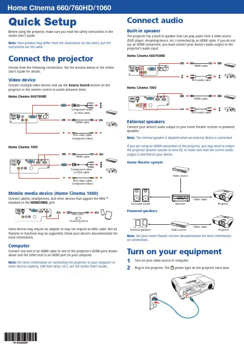
Quick SetupBefore using the projector, make sure you read the safety instructions in the online User’s Guide .Note: Your product may differ from the illustrations on this sheet, but the instructions are the same.Connect the projectorChoose from the following connections. See the sections below or the online User’s Guide for details.Video deviceConnect multiple video devices and use the Source Search button on the projector or the remote control to switch between them.Home Cinema 660/760HD(composite video)to VGA cableRCA video cable (composite video)Mobile media device (Home Cinema 1060)Connect tablets, smartphones, and other devices that support the MHL ™ standard to the HDMI2/MHLport.Some devices may require an adapter or may not require an MHL cable. Not all features or functions may be supported. Check your device’s documentation for more information.ComputerConnect one end of an HDMI cable to one of the projector’s HDMI ports shown above and the other end to an HDMI port on your computer.Note: For more information on connecting the projector to your computer or other devices (camera, USB flash drive, etc.), see the online User’s Guide .Connect audioBuilt-in speakerThe projector has a built-in speaker that can play audio from a video source (DVD player, streaming device, etc.) connected by an HDMI cable. If you do not use an HDMI connection, you must connect your device’s audio output to the projector’s audio input.Home Cinema 660/760HDHome Cinema 1060External speakersConnect your device’s audio output to your home theater receiver or powered speakers.Note: The internal speaker is disabled when an external device is connected.If you are using an HDMI connection to the projector, you may need to reduce the projector speaker volume to zero (0), or make sure that the correct audio output is selected on your device.Home theater systemVideo sourceSurround soundReceiverPowered speakersNote: See your home theater receiver documentation for more information on connections.Turn on your equipment1T urn on your video source or computer.2P lug in the projector. Thepower light on the projector turns blue.3 Open the A/V Mute slide all the way.4 P ress the power button on the projector or remote control. Theprojector beeps, the Statuslight flashes blue, and then stays on.Note: To shut down the projector, press the power button twice.5 U se the arrow buttons on the remote control to highlight any options onthe Home screen that appears, then press to select it. You can switchbetween projection sources and quickly access various adjustment optionsfrom this screen.6 T he default language of the menu system is English. To select anotherlanguage, press the Menu button on the projector or the remotecontrol. Select Extended and press . Select Language and press .Select your language and press . Press the Menu button to exit themenu system.Adjust the image1 I f you don’t see an image, press the Source Search button on theprojector or the remote control to select the image source.Note: If you still see a blank screen or have other display problems, see2 T3 Hor W (enlarge) button on the projector.H ome Cinema 760HD/1060: To reduce or enlarge the image, turn thezoom ring.4To sharpen the image, turn the focus ring.5 I f your image looks like or , you may have placed the projectoroff to one side of the screen at an angle. Place the projector directly infront of the center of the screen, facing the screen squarely. If you can’tmove the projector, use the horizontal keystone slider on the projectorto correct the image shape.6 Ycorrect it.Using the remote controlInstall the batteries as shown (two AA batteries).Choose which sourceto displayTurn projectoron and offAccess projectormenusdisplayAccess the HomescreenNavigate projectormenusFor more information on using the remote control, see the onlineUser’s Guide.TroubleshootingI f you see a blank screen or the No signal message after turning on your computer or video device, check the following:•M ake sure the Status light on the projector is blue and not flashing, and the A/V Mute slide is open.•P ress the Source Search button on the projector or remote control to switch to the correct image source, if necessary.•P ress the Home button on the projector or remote control to verify the source input and settings.•O n Windows® 7 or later, hold down the Windows key and press P at the same time, then click Duplicate.•I f you’re using a Windows laptop, press the function key on your keyboard that lets you display on an external monitor. It may be labeled CRT/LCD or have an icon such as . You may have to hold down the Fn key while pressing it (such as Fn + F7). Wait a moment for the display to appear.•I f you’re using a Mac laptop, open System Preferences and select Displays. Click the Arrangement tab and select the Mirror Displayscheckbox.Where to get helpManualFor more information about using the projector, click the icon on your desktop to access the online manual (requires an Internet connection). If you don’t have a User’s Guide icon, you can install it from the projector CD or go to the Epson website, as described below.Telephone support servicesTo use the Epson® PrivateLine® Support service, call (800) 637-7661. This service is available for the duration of your warranty period. You may also speak with a support specialist by calling (562) 276-4394 (U.S.) or (905) 709-3839 (Canada). Support hours are 6 am to 8 pm, Pacific Time, Monday through Friday, and7 am to 4 pm, Pacific Time, Saturday. Days and hours of support are subject to change without notice. Toll or long distance charges may apply.Internet supportVisit /support (U.S.) or www.epson.ca/support (Canada) for solutions to common problems. You can download utilities and documentation, get FAQs and troubleshooting advice, or e-mail Epson. RegistrationRegister today to get product updates and exclusive offers. You can use the CD included with your projector or register online at /webreg.Optional accessoriesFor a list of optional accessories, see the online User’s Guide.You can purchase screens or other accessories from an Epson authorized reseller. To find the nearest reseller, call 800-GO-EPSON (800-463-7766).Or you can purchase online at (U.S. sales) orwww.epsonstore.ca (Canadian sales).NoticesDeclaration of ConformityAccording to 47CFR, Part 2 and 15, Class B Personal Computers and Peripherals; and/or CPU Boards and Power Supplies used with Class B Personal Computers.We: Epson America, Inc.Located at: 3840 Kilroy Airport Way, MS: 3-13, Long Beach, CA 90806 Telephone: (562) 981-3840Declare under sole responsibility that the product identified herein, complies with47CFR Part 2 and 15 of the FCC rules as a Class B digital device. Each product marketed, is identical to the representative unit tested and found to be compliant with the standards. Records maintained continue to reflect the equipment being produced can be expected to be within the variation accepted, due to quantity production and testing on a statistical basis as required by 47CFR 2.909. Operation is subject to the following two conditions: (1) this device may not cause harmful interference, and (2) this device must accept any interference received, including interference that may cause undesired operation.Trade Name: EpsonType of Product: LCD ProjectorModel: H847A/H848A/H849AMarketing Name: Home Cinema 660/760HD/1060Wireless LAN Safety and SpecificationsContains wireless LAN module model: WN7122BEP (Home Cinema 1060)This document provides safety instructions and describes the specifications. Read this document carefully before use to ensure your safety and product performance.Data transmission is always initiated by software, which is the passed down throughthe MAC, through the digital and analog baseband, and finally to the RF chip. Several special packets are initiated by the MAC. These are the only ways the digital baseband portion will turn on the RF transmitter, which it then turns off at the end of the packet. Therefore, the transmitter will be on only while one of the aforementioned packets is being transmitted. In other words, this device automatically discontinue transmission in case of either absence of information to transmit or operational failure.This equipment is restricted to indoor operation only.U.S. FCC NoticesContains FCC ID: BKMAE-7122This device complies with Part 15 of the FCC Rules. Operation is subject to the following two conditions: (1) This device may not cause harmful interference, and (2) this device must accept any interference received, including interference that may cause undesired operation.This equipment has been tested and found to comply with the limits for a Class Bdigital device, pursuant to Part 15 of the FCC Rules. These limits are designed to provide reasonable protection against harmful interference in a residential installation. This equipment generates, uses and can radiate radio frequency energy and, if not installed and used in accordance with the instructions, may cause harmful interference to radio communications. However, there is no guarantee that interference will not occur ina particular installation. If this equipment does cause harmful interference to radioor television reception, which can be determined by turning the equipment off and on, the user is encouraged to try to correct the interference by one of the following measures:• Reorient or relocate the receiving antenna.• Increase the separation between the equipment and receiver.• C onnect the equipment into an outlet on a circuit different from that to which the receiver is connected.• Consult the dealer or an experienced radio/TV technician for help.Caution: Changes or modifications not expressly approved by the party responsible for compliance could void the user’s authority to operate this equipment. Properly shielded and grounded cables and connectors must be used for connection to host computers and / or peripherals in order to meet FCC emission limits.This transmitter must not be co-located or operating in conjunction with any other antenna or transmitter.This equipment complies with FCC radiation exposure limits set forth for an uncontrolled environment and meets the FCC radio frequency (RF) Exposure Guidelines. This equipment should be installed and operated keeping the radiator at least 7.8 inches (20 cm) or more away from person’s body.Industry Canada (IC) NoticesContains IC: 1052D-7122CAN ICES-3 (B)/NMB-3 (B)This device complies with Industry Canada’s licence-exempt RSSs. Operation is subjectto the following two conditions: (1) This device may not cause interference; and (2) This device must accept any interference, including interference that may cause undesired operation of the device.This equipment complies with IC radiation exposure limits set forth for an uncontrolled environment and meets RSS-102 of the IC radio frequency (RF) Exposure rules. This equipment should be installed and operated keeping the radiator at least 7.8 inches (20 cm) or more away from person’s body.Epson America, Inc. Limited WarrantyTwo-Year Projector Limited Warranty and 90-Day Lamp Limited WarrantyWhat Is Covered : Epson America, Inc. (“Epson”) warrants to the original retail purchaser of the Epson projector product enclosed with this limited warranty statement that the product, if purchased new and operated in the United States, Canada, or Puerto Rico will be free from defects in workmanship and materials for a period of two years from the date of original purchase. This limited warranty applies only to the projector and not to the projector lamp, which carries a limited warranty period of ninety days from the date of original purchase. For warranty service, you may be required to provide proof of the date of original purchase.What Epson Will Do To Correct Problems : If your product requires service during thelimited warranty period, please call Epson at the number on the bottom of this statement and be prepared to provide the model, serial number, and, if required, date of original purchase. If Epson confirms that warranty service is required, Epson will, at its option, repair or replace the defective unit, without charge for parts or labor. If Epson authorizes an exchange for the defective unit, Epson will ship a replacement product to you, freight prepaid, so long as you use an address in the United States, Canada, or Puerto Rico. You are responsible for securely packaging the defective unit and returning it to Epson within five working days of receipt of the replacement. Epson requires a debit or a credit card number to secure the cost of the replacement product in the event that you fail to return the defective one. If Epson authorizes repair instead of exchange, Epson will direct you to send your product to Epson or its authorized service center, where the product will be repaired and sent back to you. You are responsible for packing the product and for all postage or shipping costs to and from the Epson authorized service center. When warranty service involves the exchange of the product or of a part, the item replaced becomes Epson property. The exchanged product or part may be new or refurbished to the Epson standard of quality. If service cannot be provided on the product for any reason and Epson no longer sells the same model, Epson will replace your product with a model of equal or superior value. Replacement products or parts assume the remaining warranty period of the original product. If Epson replaces the lamp as part of thewarranty service, the replacement lamp carries the limited 90-day warranty stated above.What This Warranty Does Not Cover : This warranty covers only normal use in the United States, Canada, or Puerto Rico.This warranty does not cover the following:•Excessive continual use •Consumables such as filters •Installation or removal• C osmetic damage caused by handling or normal wear and tear during usage • Damage caused by failure to properly maintain the projector (see your online User’s Guide for details)• D amage caused by interaction with non-Epson products, such as add-in cards or cables • A ny problem resulting from misuse, abuse, improper installation, neglect, improper shipping, disasters such as fire, flood, and lightning, improper electrical current,software problems, exposure to chemical smoke, or excessive humidity • Any problem resulting from service by other than Epson or an Epson Authorized Servicer Epson is not responsible for warranty service should the Epson label or logo or the rating label or serial number be removed. This warranty is not transferrable. Epson is not responsible for your data or applications, which cannot be restored and should be backed up by you. Postage, insurance, or shipping costs incurred in presenting your Epson product for carry-in warranty service are your responsibility. If a claimed defect cannot be identified or reproduced in service, you will be held responsible for costs incurred.DISCLAIMER OF OTHER WARRANTIES : THE WARRANTY AND REMEDY PROVIDEDABOVE ARE EXCLUSIVE AND IN LIEU OF ALL OTHER EXPRESS OR IMPLIED WARRANTIES INCLUDING, BUT NOT LIMITED TO, THE IMPLIED WARRANTIES OF MERCHANTABILITY , NONINFRINGEMENT OR FITNESS FOR A PARTICULAR PURPOSE. SOME LAWS DO NOT ALLOW THE EXCLUSION OF IMPLIED WARRANTIES. IF THESE LAWS APPLY , THEN ALL EXPRESS AND IMPLIED WARRANTIES ARE LIMITED TO THE WARRANTY PERIOD IDENTIFIED ABOVE. UNLESS STATED HEREIN, ANY STATEMENTS OR REPRESENTATIONS MADE BY ANY OTHER PERSON OR FIRM ARE VOID.EXCLUSION OF DAMAGES; EPSON’S MAXIMUM LIABILITY : IN NO EVENT SHALL EPSON OR ITS AFFILIATES BE LIABLE FOR ANY SPECIAL, INCIDENTAL, OR CONSEQUENTIAL DAMAGES OR ANY LOST PROFITS RESULTING FROM THE USE OR INABILITY TO USE THE EPSON PRODUCT, WHETHER RESULTING FROM BREACH OF WARRANTY OR ANY OTHER LEGAL THEORY . IN NO EVENT SHALL EPSON OR ITS AFFILIATES BE LIABLE FOR DAMAGES OF ANY KIND IN EXCESS OF THE ORIGINAL RETAIL PURCHASE PRICE OF THE PRODUCT.Arbitration, Governing Laws : Any dispute, claim or controversy arising out of or relating to this warranty shall be determined by arbitration in Los Angeles County, California before a single arbitrator. The arbitration shall be administered by JAMS pursuant to its Comprehensive Arbitration Rules and Procedures. Judgment on the award may beentered in any court having jurisdiction. Any action must be brought within three months of the expiration of the warranty. This clause shall not preclude parties from seeking provisional remedies in aid of arbitration from a court of appropriate jurisdiction. This warranty shall be construed in accordance with the laws of the State of California, except this arbitration clause which shall be construed in accordance with the Federal Arbitration Act.Other Rights You May Have : This warranty gives you specific legal rights, and you may also have other rights which vary from jurisdiction to jurisdiction. Some jurisdictions do not allow limitations on how long an implied warranty lasts, or allow the exclusion or limitation of incidental or consequential damages, so the above limitations or exclusions may not apply to you.In Canada, warranties include both warranties and conditions.To find the Epson Authorized Reseller nearest you, please visit in the U.S. or www.epson.ca in Canada.To find the Epson Customer Care Center nearest you, please visit/support in the U.S. or www.epson.ca/support in Canada.To contact the Epson Connection SM , please call (800) 637-7661 or (562) 276-4394 in the U.S. and (905) 709-3839 in Canada or write to Epson America, Inc., P .O. Box 93012,Long Beach, CA 90809-3012.EPSON is a registered trademark and EPSON Exceed Your Vision is a registered logomark of Seiko Epson Corporation. PrivateLine is a registered trademark and Epson Connection is a service mark of Epson America, Inc.Mac is a trademark of Apple Inc., registered in the U.S. and other countries.General Notice: Other product names used herein are for identification purposes only and may be trademarks of their respective owners. Epson disclaims any and all rights in those marks.This information is subject to change without notice. © 2017 Epson America, Inc., 4/17 CPD-53626。
目 录1、产品介绍 (1)1)关于产品 (2)2)产品及其附件 (2)3)产品示意图 (2)4)感应区域 (3)5)系统需求 (3)2、配件说明 (4)1)压感笔 (5)2)笔芯更换 (6)3)笔尖双击 (7)4)压感笔放置 (7)3、数位板的连接方式 (8)1)连接方式 (9)2)数位板指示灯状态说明 (9)4、驱动程序安装 (10)1)安装前注意事项 (11)2)Windows系统下驱动安装方式 (11)3)Mac系统下驱动安装方式 (12)5、数位板功能设定 (14)1)Windows系统下设定指南 (15)① 开启数位板控制面板 (15)② 控制面板概览 (15)③ 笔设置 (16)④ 屏幕映射 (17)⑤ 压感调节 (23)⑥ 模式选择 (24)⑦ 快捷设定 (24)⑧ 导入/导出配置 (29)⑨ 软件更新 (29)2)Mac系统下设定指南 (30)① 开启数位板控制面板 (30)② 设定选项 (30)③ 笔 (31)④ 屏幕 (33)⑤ 数位板区域 (35)⑥ 快捷键 (36)⑦ 信息页面 (39)6、驱动程序卸载 (40)1)Windows系统 (41)2)Mac系统 (41)7、常见问题 (42)8、售后服务 (44)第一章产品介绍感谢您选购友基绘图系列产品。
本产品不仅可实现无纸化数字绘画,更导入了先进的无源技术,从而带给您更便捷的创作、绘画体验。
使用者可将其与电脑连接,直接以压感笔于数位板上进行输入及绘图操作,可应用于多媒体绘画教学及相关领域。
使用此产品前,请确认下列所列附件均置于包装箱内。
①UG-1060数板;②附件盒内含:如果上述附件欠缺或损坏请与您的购买点联系,如无法解决问题,请联系友基售后服务中心。
图1-3-1.产品示意图图1-4.感应区域①操作系统:PC:Windows7/8/10(32/64bit);Mac:Mac OS X 10.8或以上版本;②处理器:Pentium 233MHz以上;③内存:64MB以上;④硬盘空间:128MB以上可用空间;⑤光驱:4倍速光驱或更高;⑥接口:USB接口。
MANUALCÁMARA IP RÓBOTICA APP TUYA SMART – 1080PREF: 106058DESCRIPCIÓN DE FUNCIONES PRINCIPALESDETALLES FÍSICOS DEL PRODUCTO-DESCARGA DE APLICACIÓNBusque y descargue la APP “Tuya Smart” desde Play Store o Apple Store.-REGISTRO DE USUARIO / INICIO DE SESION CON USUARIO EXISTENSTEREGISTRO POR PRIMERA VEZSí usted no tiene una cuenta en TUYA SMART, puede generar una cuenta o iniciar sesión con un código vía correo electrónico. Por favor lea la página inicial y luego la siguiente para el proceso de registro.Haga clic en CREA CUENTA NUEVA, ingrese a la página de políticas de privacidad, clic en DE ACUERDO e ingrese a la página de registro para correo electrónico. Luego clic en OBTENGA EL CÓDIGO DE VERIFICACIÓN. Digítelo e inicie sesión.INICIO DE SESIÓN CON CUENTA EXISTENTESí usted tiene una cuenta registrada, puede omitir la creación de una nueva cuenta, Haga clic en INICIAR SESION CON UNA C UENTA EXISTENTE. Ingrese a la página para iniciar sesión1)El sistema automáticamente seleccionará el país o puede hacerlo usted manualmente.2)Ingrese su correo electrónico registrado y su contraseña para iniciar sesión.-CONFIGURACIÓNNotas importantes:Este dispositivo solo soporta frecuencias de banda de 2.4GHz.NO puede conectarse a redes de 5GHz.Cuando se encuentre configurando el dispositivo con su red WiFi, mantenga su teléfono celular y el dispositivo cercanos al router para acelerar la velocidad de configuración y conexión.Ingrese correctamente la contraseña establecida para iniciar sesión.El dispositivo sólo puede agregarse a una cuenta de la APP, si ya ha sido vinculado a una cuenta no podrá ser agregado a otra cuenta.El dispositivo será desvinculado en cuanto usted lo elimine a través de la aplicación. Se reiniciará automáticamente y emitirá un mensaje de voz cada 30 segundos, lo cual indicará que se encuentra en modo de configuración.PROCESO DE CONFIGURACIONPaso 1.- Abra la aplicación “TuyaSmart” y haga clic en “+” en la esq uina superior derecha o en “Añadir un dispositivo”.Después seleccione el tipo de dispositivo, opción Video vigilancia y en este caso es una“Cámara de seguridad inteligente WI-FI”.Paso 2.- Asegúrese de que el dispositivo está encendido en modo de configuración y haga clic en “siguiente paso” para continuar.Paso 3.- Elija red WiFi a la que desee añadir la cámara e introduzca la contraseña de la red. Haga clic en “Confirmar”. Coloque el código QR que le aparecerá en la pantalla de su teléfo no frente al lente de la cámara para su lectura. Al oir el asistente de voz, clic en OIR TONO DE AVISOPaso 4.- Haga clic cuando haya escuchado el tono de aviso y espere a que termine la configuración de la cámara.Paso 5.- Cuando muestre la conexión al 100% el dispositivo ha sido añadido.Usted podrá cambiar el nombre del dispositivo, compartirlo y comenzar a disfrutar de sus funciones local o remotamente.8. INTERFAZ DE LA VISTA PREVIA9. FUNCIONES DE VIDEO EN LA APP:Advertencias de uso:∙Intente mantener la cámara fuera de espacios metálicos o bloqueados por muebles u hornos de microondas que obstruyan las señales de sonido, video y datos.∙Procure instalar en los sitios más cercanos a la cobertura WiFi de su hogar u oficina.∙No gire bruscamente la cámara. Puede dañar el eje de rotación del motor.∙Funciona únicamente con cable USB y adaptador 5VDC a 1.5 Amperios. Verifique que el adaptador y el cable estén en buen estado, para evitar corto circuitos en la cámara.∙Aleje la cámara de cualquier tipo de humedad ó líquido corrosivo que la pueda averiar en su parte física y electrónica.∙Evite dejar caer la cámara. El golpe genera daños en su tarjeta principal, lente y motor.∙Incruste el conector del cable USB al puerto de energía de la cámara con cuidado, para no generarle un daño.。
Windows 10中高漫数位板(1060PRO)的使用说明
曾棕根
2020年4月19日星期日
一、购买网址
京东网上搜索“高漫数位板”,
二、进入官网,下载驱动
官网
驱动:
三、安装驱动
运行Gaomon Windows Driver_v14.8.90.,直接安装它。
四、设置驱动
把高漫数位板直接插入电脑的USB接口,再运行Gaomon Tablet软件,设置界面如下:
最后,点击“应用”按钮。
五、使用Windows 10操作系统中的Windows Ink软件直接写字
点击全屏截图,在截图界面里右上角点击“缩放”-“查看实际大小”:
现在可以在上面写写画画了,可以发现,笔迹当中的锯齿被自动消除了,而且没有增加笔锋,很灵敏:
六、重启Windows 10后,不会再运行Gaomon Tablet软件了,也不必运行它。
如果你要设置高漫数位板时,你可以再运行它去设置驱动。
注意,一定是用Windows Ink软件去屏幕上写字。
如果你在其它软件里去写字,笔划中不会消除锯齿,太难看了:
最后,把笔上的按键抠出来,免得老按到它:。
山 东 化 工 收稿日期:2019-09-20作者简介:戴超兰(1992—),女,湖南长沙人,助教,硕士,主要从事文件检验研究。
触摸板数字手写签名与中性笔签名字迹的比较与分析戴超兰1,赵智浩2(1.湖南警察学院,湖南长沙 410000;2.衡山县公安局,湖南衡阳 421000)摘要:触摸板数字手写签名是一种新型数字签名,广泛运用于公安、金融交易等领域。
本文从概貌特征、笔顺特征、运笔特征、搭配比例特征、布局特征和笔痕特征六个方面对触摸板数字手写签名笔迹与中性笔手写签名笔迹进行特征比对分析。
实验结果表明两种签名笔迹在概貌特征、布局和笔顺特征方面具有稳定性,在运笔特征、搭配比例和笔痕特征方面易变,为数字手写签名笔迹和中性笔签名笔迹的比对检验提供一定的依据。
关键词:中性笔;触摸板;签名笔迹;比对分析中图分类号:D918.92 文献标识码:A 文章编号:1008-021X(2019)22-0130-03 触屏手写电子签名,是利用触摸屏和手写互动软件系统,使用特殊笔或直接用手指在屏幕上签写的新型电子签名。
从笔迹形成机理来说,触屏手写电子同纸笔签名一样,理论上是可以鉴定的,因为其产生的笔迹是可以反映个人的书写能力,从而折射出书写者的书写特点[1]。
因其书写流畅,效果逼真,安全高效的特点,在公安笔录系统中,正在逐步取代传统笔录签字,但由于书写工具和书写载体的变化,当事人在使用触摸手写板进行签名时书写习惯和心理活动都会出现变化,容易造成签名笔迹变化,从而给笔迹检验增加难度[2]。
研究该新型笔迹特征变化,为数字手写签名笔迹的检验提供依据显得尤为重要。
1 实验仪器和设备扫描仪:EPSONGV39,显微镜:徕卡125C,图像处理软件:PhotoshopCS3。
1.1 实验原理1.1.1 笔迹检验原理笔迹检验是依据书写人书写动作技能与日常书写习惯的痕迹,通过分别与比对检验两个过程,针对两个或多个笔迹特征的异同点进行判断,以此分析书写人的书写习惯特征,判断书写字迹是否由书写人所写。
TH1060数码投影机用户手册欢迎使用目录重要安全说明 (3)简介 (7)投影机特点 (7)物品清单 (8)投影机外观概览 (9)控制装置和功能 (10)安装投影机 (15)选择位置 (15)获取首选的投影图像大小 (16)连接 (19)连接计算机或显示器 (19)连接视频源设备 (20)连接HDMI信号源设备 (21)操作 (25)启动投影机 (25)使用菜单 (26)投影机安全 (26)使用密码功能 (27)切换输入信号 (29)调节投影图像 (30)放大并搜索细部 (32)选择宽高比 (32)优化图像 (35)隐藏图像 (40)设置休眠计时器 (40)远程接收器 (41)冻结图像 (41)在高海拔环境中使用 (41)调节声音......................42个性化投影机菜单显示. (43)关闭投影机 (43)菜单操作 (44)维护 (52)维护投影机 (52)灯泡信息 (53)故障排除 (59)规格 (60)投影机规格 (60)外形尺寸 (61)时序表 (62)保修及版权信息 (66)目录2重要安全说明您的投影机经过设计和测试,符合最新信息技术设备的安全标准。
然而,为确保安全使用本产品,按本手册中提及和产品上标记的说明进行操作是至关重要的。
重要安全说明3重要安全说明4重要安全说明5重要安全说明6简介投影机特点此投影机集成了高性能的光学引擎投影技术和用户友好的设计以提供高可靠性和易用性。
此投影机具有下列特点。
• 快速自动搜索可提高信号检测速度。
• 可选的密码保护功能• 3D 色彩管理可按您的喜好进行色彩调节• 可选快速冷却功能,能缩短投影机冷却时间• 单键自动调整,可显示最佳图像质量• 数码梯形失真校正,可校正失真变形的图像• 为数据/视频显示提供可调节的颜色平衡控制• 高亮度投影灯泡• 能够显示10.70亿颜色• 多语言屏显(OSD)菜单• 可切换到正常和经济模式以降低功耗• 兼容分量HDTV (YP b P r)• 高质量手动变焦镜头• 当连接了音频输入时,内置扬声器提供混合单声道音频• 强大的AV功能可提供高质量视频图像• HDCP兼容• 双HDMI 输入• 自动梯形校正功能可自动校正图像的梯形失真投影图像的亮度与使用环境的照明条件和所选输入信号对比度/亮度设置有关,并与投影距离成正比。