DS3231
- 格式:pdf
- 大小:449.27 KB
- 文档页数:19
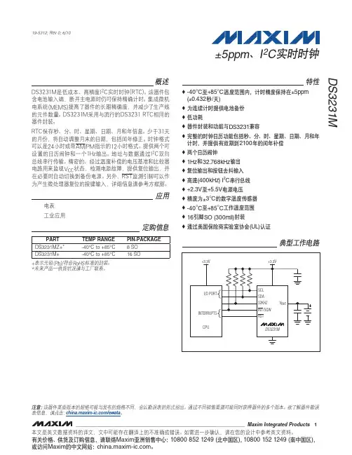
DS3231 高精度I2C 实时时钟(R
DS3231 是低成本、高精度I2C 实时时钟(RTC),具有集成的温补晶振(TCXO)和晶体。
该器件包含电池输入端,断开主电源时仍可保持精确的计时。
集成晶振提高了器件的长期精确度,并减少了生产线的元件数量。
DS3231 提供商用级和工业级温度范围,采用16 引脚300mil 的SO 封装。
RTC 保存秒、分、时、星期、日期、月和年信息。
少于31 天的月份,将自动调整月末的日期,包括闰年的修正。
时钟的工作格式可以是24 小时或带/AM/PM 指示的12 小时格式。
提供两个可设置的日历闹钟和一个可设置的方波输出。
地址与数据通过I²C 双向总线串行传输。
精密的、经过温度补偿的电压基准和比较器电路用来监视VCC 状态,检测电源故障,提供复位输出,并在必要时自动切换到备份电源。
另外,
/RST 监视引脚可以作为产生µP 复位的手动输入。
关键特性
0°C至+40°C范围内精度为±2ppm
-40°C至+85°C范围内精度为±3.5ppm
为连续计时提供电池备份输入。
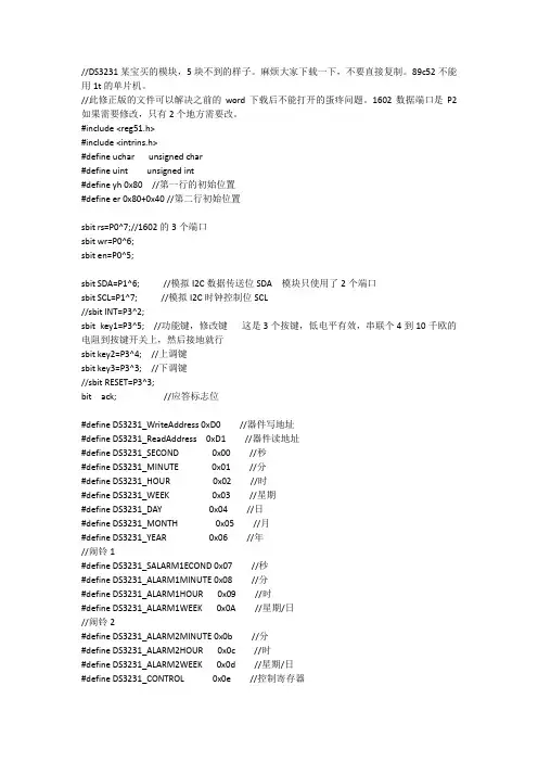
//DS3231某宝买的模块,5块不到的样子。
麻烦大家下载一下,不要直接复制。
89c52不能用1t的单片机。
//此修正版的文件可以解决之前的word下载后不能打开的蛋疼问题。
1602数据端口是P2如果需要修改,只有2个地方需要改。
#include <reg51.h>#include <intrins.h>#define uchar unsigned char#define uint unsigned int#define yh 0x80 //第一行的初始位置#define er 0x80+0x40 //第二行初始位置sbitrs=P0^7;//1602的3个端口sbitwr=P0^6;sbit en=P0^5;sbit SDA=P1^6; //模拟I2C数据传送位SDA 模块只使用了2个端口sbit SCL=P1^7; //模拟I2C时钟控制位SCL//sbit INT=P3^2;sbit key1=P3^5; //功能键,修改键这是3个按键,低电平有效,串联个4到10千欧的电阻到按键开关上,然后接地就行sbit key2=P3^4; //上调键sbit key3=P3^3; //下调键//sbit RESET=P3^3;bit ack; //应答标志位#define DS3231_WriteAddress 0xD0 //器件写地址#define DS3231_ReadAddress 0xD1 //器件读地址#define DS3231_SECOND 0x00 //秒#define DS3231_MINUTE 0x01 //分#define DS3231_HOUR 0x02 //时#define DS3231_WEEK 0x03 //星期#define DS3231_DAY 0x04 //日#define DS3231_MONTH 0x05 //月#define DS3231_YEAR 0x06 //年//闹铃1#define DS3231_SALARM1ECOND 0x07 //秒#define DS3231_ALARM1MINUTE 0x08 //分#define DS3231_ALARM1HOUR 0x09 //时#define DS3231_ALARM1WEEK 0x0A //星期/日//闹铃2#define DS3231_ALARM2MINUTE 0x0b //分#define DS3231_ALARM2HOUR 0x0c //时#define DS3231_ALARM2WEEK 0x0d //星期/日#define DS3231_CONTROL 0x0e //控制寄存器#define DS3231_STATUS 0x0f //状态寄存器#define BSY 2 //忙#define OSF 7 //振荡器停止标志#define DS3231_XTAL 0x10 //晶体老化寄存器#define DS3231_TEMPERATUREH 0x11 //温度寄存器高字节(8位) #define DS3231_TEMPERATUREL 0x12 //温度寄存器低字节(高2位)uchar a,miao,shi,fen,ri,yue,nian,week,temp1,temp2,key1n,temp;uchar code tab1[]={"2017- - FRI"};uchar code tab2[]={" : : ."};/*uchar HEX2BCD(ucharval) //B码转换为BCD码{uchar k;k=(val)/10*16+(val)%10;return k;}*/ucharBCD_Decimal(ucharbcd){uchar Decimal;Decimal=bcd>>4;return(Decimal=Decimal*10+(bcd&=0x0F));}void delayus(uint us){while (us--);}void Start_I2C(){SDA=1; //发送起始条件的数据信号delayus(1);SCL=1;delayus(5); //起始条件建立时间大于4.7us,延时SDA=0; //发送起始信号delayus(5); // 起始条件锁定时间大于4μsSCL=0; //钳住I2C总线,准备发送或接收数据delayus(2);}void Stop_I2C(){SDA=0; //发送结束条件的数据信号delayus(1); //发送结束条件的时钟信号SCL=1; //结束条件建立时间大于4usdelayus(5);SDA=1; //发送I2C总线结束信号delayus(4);}void SendByte(uchar c){ucharBitCnt;for(BitCnt=0;BitCnt<8;BitCnt++) //要传送的数据长度为8位{if((c<<BitCnt)&0x80)SDA=1; //判断发送位elseSDA=0;delayus(1);SCL=1; //置时钟线为高,通知被控器开始接收数据位delayus(5); //保证时钟高电平周期大于4μsSCL=0;}delayus(2);SDA=1; //8位发送完后释放数据线,准备接收应答位delayus(2);SCL=1;delayus(3);if(SDA==1)ack=0;elseack=1; //判断是否接收到应答信号SCL=0;delayus(2);}ucharRcvByte()ucharretc;ucharBitCnt;retc=0;SDA=1; //置数据线为输入方式for(BitCnt=0;BitCnt<8;BitCnt++){delayus(1);SCL=0; //置时钟线为低,准备接收数据位delayus(5); //时钟低电平周期大于4.7μsSCL=1; //置时钟线为高使数据线上数据有效delayus(3);retc=retc<<1;if(SDA==1)retc=retc+1; //读数据位,接收的数据位放入retc中delayus(2);}SCL=0;delayus(2);return(retc);}void Ack_I2C(bit a){if(a==0)SDA=0; //在此发出应答或非应答信号elseSDA=1;delayus(3);SCL=1;delayus(5); //时钟低电平周期大于4μsSCL=0; //清时钟线,钳住I2C总线以便继续接收delayus(2);}ucharwrite_byte(ucharaddr, ucharwrite_data){Start_I2C();SendByte(DS3231_WriteAddress);if (ack == 0)return 0;SendByte(addr);if (ack == 0)return 0;SendByte(write_data);if (ack == 0)return 0;Stop_I2C();delayus(10);return 1;}ucharread_current(){ucharread_data;Start_I2C();SendByte(DS3231_ReadAddress);if(ack==0)return(0);read_data = RcvByte();Ack_I2C(1);Stop_I2C();return read_data;}ucharread_random(ucharrandom_addr) {Start_I2C();SendByte(DS3231_WriteAddress);if(ack==0)return(0);SendByte(random_addr);if(ack==0)return(0);return(read_current());}/*void ModifyTime(ucharyea,ucharmon,ucharda,ucharhou,ucharmin,ucharsec,uchar week) {uchar temp=0;temp=HEX2BCD(yea);write_byte(DS3231_YEAR,temp); //修改年temp=HEX2BCD(mon);write_byte(DS3231_MONTH,temp); //修改月temp=HEX2BCD(da);write_byte(DS3231_DAY,temp); //修改日temp=HEX2BCD(hou);write_byte(DS3231_HOUR,temp); //修改时temp=HEX2BCD(min);write_byte(DS3231_MINUTE,temp); //修改分temp=HEX2BCD(sec);write_byte(DS3231_SECOND,temp); //修改秒temp=HEX2BCD(week);write_byte(DS3231_WEEK,temp); //修改星期}*//******************液晶写入************************/void write_1602com(uchar com)//液晶写入指令函数{rs=0;//置为写入命令P2=com;//送入数据delayus(1000);en=1;//拉高使能端delayus(1000);en=0;//完成高脉冲}void write_1602dat(uchardat){rs=1;//置为写入数据P2=dat;//送入数据delayus(1000);en=1;delayus(1000);en=0;}/*********************over***********************/ void lcd_init()//液晶初始化函数{ wr=0;write_1602com(0x38);//设置液晶工作模式write_1602com(0x0c);//开显示不显示光标write_1602com(0x06);//整屏不移动,指针加一write_1602com(0x01);write_1602com(yh+1);//字符写入的位置for(a=0;a<14;a++){write_1602dat(tab1[a]);//delay(3);}write_1602com(er);for(a=0;a<12;a++){write_1602dat(tab2[a]);//delay(3);}write_1602com(er+14); //写温度符号write_1602dat(0xdf);write_1602dat(0x43);}void write_sfm(ucharadd,uchardat)//写时分秒及温度{uchargw,sw;gw=dat%10;sw=dat/10;write_1602com(er+add);write_1602dat(0x30+sw);write_1602dat(0x30+gw);}void write_nyr(ucharadd,uchardat) //写日期{uchargw,sw;gw=dat%10;sw=dat/10;write_1602com(yh+add);write_1602dat(0x30+sw);write_1602dat(0x30+gw);}void write_week(uchar week)//写星期函数{write_1602com(yh+0x0c);switch(week){case 1:write_1602dat('M');//delay(5);write_1602dat('O');//delay(5);write_1602dat('N');break;case 2:write_1602dat('T');//delay(5);write_1602dat('U');//delay(5);write_1602dat('E');break;case 3:write_1602dat('W');//delay(5);write_1602dat('E');//delay(5);write_1602dat('D');break;case 4:write_1602dat('T');//delay(5);write_1602dat('H');//delay(5);write_1602dat('U');break;case 5:write_1602dat('F');//delay(5);write_1602dat('R');//delay(5);write_1602dat('I');break;case 6:write_1602dat('S');//delay(5);write_1602dat('T');//delay(5);write_1602dat('A');break;case 7:write_1602dat('S');//delay(5);write_1602dat('U');//delay(5);write_1602dat('N');break;}}void keyscan(){if(key1==0)//key1为功能键{delayus(5000);if(key1==0){while(!key1);key1n++;if(key1n==9)key1n=1;switch(key1n){case 1: TR0=0;//关闭定时器//TR1=0;write_1602com(er+0x06);//写入光标位置write_1602com(0x0f);//设置光标为闪烁break;case 2: write_1602com(er+3);//fen//write_1602com(0x0f);break;case 3: write_1602com(er+0);//shi//write_1602com(0x0f);break;case 4: write_1602com(yh+0x0d);//week//write_1602com(0x0f);break;case 5: write_1602com(yh+0x09);//ri//write_1602com(0x0f);break;case 6: write_1602com(yh+0x06);//yue//write_1602com(0x0f);break;case 7: write_1602com(yh+0x03);//nian//write_1602com(0x0f);break;case 8: write_1602com(0x0c);//设置光标不闪烁write_sfm(6,miao);//写入新的秒数temp=(miao)/10*16+(miao)%10;write_byte(DS3231_SECOND,temp); //退出时修改秒write_1602com(er+6);write_sfm(0x03,fen);temp=(fen)/10*16+(fen)%10;write_byte(DS3231_MINUTE,temp); //修改分write_1602com(er+3);TR0=1;//打开定时器break;}}}if(key1n!=0)//当key1按下以下。

使用STM32和DS3231 RTC:设置并获取时间和日期——笔记在本文中,将使用STM32开发一个驱动程序,用于在DS3231中设置和获取时间存储。
在本文中,将介绍以下内容:DS3231模块。
与STM32F411核-64的连接。
源文件。
产品图片DS3231模块DS3231是一款低成本、极其精确的I 2 C实时时钟(RTC),集成温度补偿晶体振荡器(TCXO)和晶体。
该器件集成了电池输入,并在器件的主电源中断时保持精确的计时。
晶体谐振器的集成提高了设备的长期精度,并减少了生产线中的零件数量。
RTC 维护秒、分钟、小时、星期、日期、月份和年份信息。
对于少于31 天的月份,月底的日期会自动调整,包括闰年的更正。
时钟以24 小时制或12 小时制运行,带有AM/PM 指示器。
提供两个可编程时间闹钟和一个可编程方波输出。
地址和数据通过I 2 C双向总线串行传输。
该模块可在3.3 或5 V 电压下工作,适用于许多开发平台或微控制器。
电池输入为3V,典型的CR2032 3V电池可以为模块供电并保持信息超过一年。
与STM32F411核-64的连接:在开始开发驱动器之前,需要I2C多读和多写才能使DS3231工作。
我们首先创建名称为ds3231.h 的新头文件。
在头文件中,我们将声明一个结构如下:该结构将包含以下内容:秒。
分。
小时。
月中的某天。
月。
年。
计算所需的其他数据。
此外,声明以下三个函数:首先是设置时间和数据,并以结构为参数。
第二个是从DS3231读取时间,并获取指向结构的指针。
第三个功能将打印时间。
因此,整个头文件如下所示:创建一个名称为ds3231.c 的新源代码。
在此声明以下宏:此外,还有两个功能:第一个将 dec 转换为 BCD 的方法:第二个是将 BCD 转换为 dec :为了设置时间和日期:由于我们已经超过了2000 年,因此我们将世纪位设置为1:并从给定年份中减去2000。
然后将变量转换为BCD,并将变量发送到DS3231,以设置时间和日期。
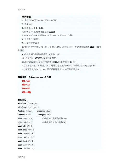
模块参数:1.尺寸:38mm(长)*22mm(宽)*14mm(高)2.重量:8g3.工作电压:3.3--5.5V4.时钟芯片:高精度时钟芯片DS32315.时钟精度:0-40℃范围内,精度2ppm,年误差约1分钟6.带2个日历闹钟7.可编程方波输出8.实时时钟产生秒、分、时、星期、日期、月和年计时,并提供有效期到2100年的闰年补偿9.芯片内部自带温度传感器,精度为±3℃10.存储芯片:AT24C32(存储容量32K)11.IIC总线接口,最高传输速度400KHz(工作电压为5V时)12.可级联其它IIC设备,24C32地址可通过短路A0/A1/A2修改,默认地址为0x5713.带可充电电池LIR2032,保证系统断电后,时钟任然正常走动接线说明,以Arduino uno r3为例:SCL→A5SDA→A4VCC→5VGND→GND代码部分:#include <reg51.h>#include <intrins.h>#define uchar unsigned char#define uint unsigned intsbit SDA=P3^6; //模拟I2C数据传送位SDAsbit SCL=P3^7; //模拟I2C时钟控制位SCLsbit INT=P3^2;sbit RESET=P3^3;sbit led0=P1^0;sbit led1=P1^1;sbit led2=P1^2;sbit led3=P1^3;sbit led4=P1^4;sbit led5=P1^5;sbit led6=P1^6;sbit led7=P1^7;bit ack; //应答标志位#define DS3231_WriteAddress 0xD0 //器件写地址#define DS3231_ReadAddress 0xD1 //器件读地址#define DS3231_SECOND 0x00 //秒#define DS3231_MINUTE 0x01 //分#define DS3231_HOUR 0x02 //时#define DS3231_WEEK 0x03 //星期#define DS3231_DAY 0x04 //日#define DS3231_MONTH 0x05 //月#define DS3231_YEAR 0x06 //年//闹铃1#define DS3231_SALARM1ECOND 0x07 //秒#define DS3231_ALARM1MINUTE 0x08 //分#define DS3231_ALARM1HOUR 0x09 //时#define DS3231_ALARM1WEEK 0x0A //星期/日//闹铃2#define DS3231_ALARM2MINUTE 0x0b //分#define DS3231_ALARM2HOUR 0x0c //时#define DS3231_ALARM2WEEK 0x0d //星期/日#define DS3231_CONTROL 0x0e //控制寄存器#define DS3231_STATUS 0x0f //状态寄存器#define BSY 2 //忙#define OSF 7 //振荡器停止标志#define DS3231_XTAL 0x10 //晶体老化寄存器#define DS3231_TEMPERATUREH 0x11 //温度寄存器高字节(8位)#define DS3231_TEMPERATUREL 0x12 //温度寄存器低字节(高2位)uchar code dis_code[11]={0xc0,0xf9,0xa4,0xb0, // 0,1,2,30x99,0x92,0x82,0xf8,0x80,0x90, 0xff}; // 4,5,6,7,8,9,offuchar data dis_buf[8];uchar data dis_index;uchar data dis_digit;uchar BCD2HEX(uchar val) //BCD转换为Byte{uchar temp;temp=val&0x0f;val>>=4;val&=0x0f;val*=10;temp+=val;return temp;}uchar HEX2BCD(uchar val) //B码转换为BCD码{uchar i,j,k;i=val/10;j=val;k=j+(i<<4);return k;}void delayus(uint us){while (us--);}void Start_I2C(){SDA=1; //发送起始条件的数据信号delayus(1);SCL=1;delayus(5); //起始条件建立时间大于4.7us,延时SDA=0; //发送起始信号delayus(5); // 起始条件锁定时间大于4μsSCL=0; //钳住I2C总线,准备发送或接收数据delayus(2);}void Stop_I2C(){SDA=0; //发送结束条件的数据信号delayus(1); //发送结束条件的时钟信号SCL=1; //结束条件建立时间大于4usdelayus(5);SDA=1; //发送I2C总线结束信号delayus(4);}void SendByte(uchar c){uchar BitCnt;for(BitCnt=0;BitCnt<8;BitCnt++) //要传送的数据长度为8位 {if((c<<BitCnt)&0x80)SDA=1;//判断发送位elseSDA=0;delayus(1);SCL=1;//置时钟线为高,通知被控器开始接收数据位delayus(5); //保证时钟高电平周期大于4μsSCL=0;}delayus(2);SDA=1;//8位发送完后释放数据线,准备接收应答位delayus(2);SCL=1;delayus(3);if(SDA==1)ack=0;elseack=1;//判断是否接收到应答信号SCL=0;delayus(2);}uchar RcvByte(){uchar retc;uchar BitCnt;retc=0;SDA=1; //置数据线为输入方式for(BitCnt=0;BitCnt<8;BitCnt++){delayus(1);SCL=0; //置时钟线为低,准备接收数据位delayus(5); //时钟低电平周期大于4.7μsSCL=1; //置时钟线为高使数据线上数据有效delayus(3);retc=retc<<1;if(SDA==1)retc=retc+1; //读数据位,接收的数据位放入retc中delayus(2);}SCL=0;delayus(2);return(retc);}void Ack_I2C(bit a){if(a==0)SDA=0; //在此发出应答或非应答信号 elseSDA=1;delayus(3);SCL=1;delayus(5); //时钟低电平周期大于4μsSCL=0; //清时钟线,钳住I2C总线以便继续接收delayus(2);}uchar write_byte(uchar addr, uchar write_data){Start_I2C();SendByte(DS3231_WriteAddress);if (ack == 0)return 0;SendByte(addr);if (ack == 0)return 0;SendByte(write_data);if (ack == 0)return 0;Stop_I2C();delayus(10);return 1;}uchar read_current(){uchar read_data;Start_I2C();SendByte(DS3231_ReadAddress);if(ack==0)return(0);read_data = RcvByte();Ack_I2C(1);Stop_I2C();return read_data;}uchar read_random(uchar random_addr) {Start_I2C();SendByte(DS3231_WriteAddress);if(ack==0)return(0);SendByte(random_addr);if(ack==0)return(0);return(read_current());}void ModifyTime(uchar yea,uchar mon,uchar da,uchar hou,uchar min,uchar sec) {uchar temp=0;temp=HEX2BCD(yea);write_byte(DS3231_YEAR,temp); //修改年temp=HEX2BCD(mon);write_byte(DS3231_MONTH,temp); //修改月temp=HEX2BCD(da);write_byte(DS3231_DAY,temp); //修改日temp=HEX2BCD(hou);write_byte(DS3231_HOUR,temp); //修改时temp=HEX2BCD(min);write_byte(DS3231_MINUTE,temp); //修改分temp=HEX2BCD(sec);write_byte(DS3231_SECOND,temp); //修改秒}void TimeDisplay(uchar Dhour,uchar Dmin,uchar Dsec){dis_buf[7]=dis_code[Dhour / 10]; // 时十位dis_buf[6]=dis_code[Dhour % 10]; // 时个位dis_buf[4]=dis_code[Dmin / 10]; // 分十位dis_buf[3]=dis_code[Dmin % 10]; // 分个位dis_buf[1]=dis_code[Dsec / 10]; // 秒十位dis_buf[0]=dis_code[Dsec % 10]; // 秒个位dis_buf[2]=0xbf; // 显示"-"dis_buf[5]=0xbf;}void DateDisplay(uchar Dyear,uchar Dmonth,uchar Dday){dis_buf[7]=dis_code[Dyear / 10]; // 年十位dis_buf[6]=dis_code[Dyear % 10]; // 年个位dis_buf[4]=dis_code[Dmonth / 10]; // 月十位dis_buf[3]=dis_code[Dmonth % 10]; // 月个位dis_buf[1]=dis_code[Dday / 10]; // 天十位dis_buf[0]=dis_code[Dday % 10]; // 天个位dis_buf[2]=0xbf; // 显示"-"dis_buf[5]=0xbf;}void get_show_time(void){uchar Htemp1,Htemp2,Mtemp1,Mtemp2,Stemp1,Stemp2;Htemp1=read_random(DS3231_HOUR); //时 24小时制Htemp1&=0x3f;Htemp2=BCD2HEX(Htemp1);Mtemp1=read_random(DS3231_MINUTE); //分Mtemp2=BCD2HEX(Mtemp1);Stemp1=read_random(DS3231_SECOND); //秒Stemp2=BCD2HEX(Stemp1);TimeDisplay(Htemp2,Mtemp2,Stemp2);}void get_show_date(void){uchar Ytemp1,Ytemp2,Mtemp1,Mtemp2,Dtemp1,Dtemp2;Ytemp1=read_random(DS3231_YEAR); //年Ytemp2=BCD2HEX(Ytemp1);Mtemp1=read_random(DS3231_MONTH); //月Mtemp2=BCD2HEX(Mtemp1);Dtemp1=read_random(DS3231_DAY); //日Dtemp2=BCD2HEX(Dtemp1);DateDisplay(Ytemp2,Mtemp2,Dtemp2);}void get_show_Temperature(void){uchar Ttemp1,Ttemp2,Ttemp3,Ttemp4;Ttemp1=read_random(DS3231_TEMPERATUREH); //温度高字节 Ttemp2=BCD2HEX(Ttemp1);Ttemp3=read_random(DS3231_TEMPERATUREL); //温度低字节Ttemp4=BCD2HEX(Ttemp3);DateDisplay(0,Ttemp2,Ttemp4);}void timer0() interrupt 1{TH0=0xFC;TL0=0x17;P2=0xff; // 先关闭所有数码管P0=dis_buf[dis_index]; // 显示代码传送到P0口P2=dis_digit;if (dis_digit & 0x80)dis_digit=(dis_digit << 1) | 0x1;elsedis_digit=(dis_digit << 1);dis_index++;dis_index&=0x07; // 8个数码管全部扫描完一遍之后,再回到第一个开始下一次扫描}void main(){uint ii = 0;RESET=0x1; //DS3231复位操作,正常操作下不需要每次都复位delayus(5000);led0=0;led1=0;led2=0;led3=0;led4=0;P0=0xff;P2=0xff;dis_digit=0xfe;dis_index=0;TimeDisplay(12, 5, 18);TMOD=0x11; // 定时器0, 1工作模式1, 16位定时方式 TH0=0xFC;TL0=0x17;TCON=0x01;IE=0x82; // 使能timer0,1 中断TR0=1;if (write_byte(DS3231_CONTROL, 0x1C) == 0)led0=1;if (write_byte(DS3231_STATUS, 0x00) == 0)led1=1;ModifyTime(10,6,13,15,30,00); //初始化时钟,2010/6/13,15/30/00//小时采用24小时制while(1){//get_show_date(); //显示日期//get_show_Temperature(); //显示温度get_show_time(); //显示时间delayus(50000);}}。
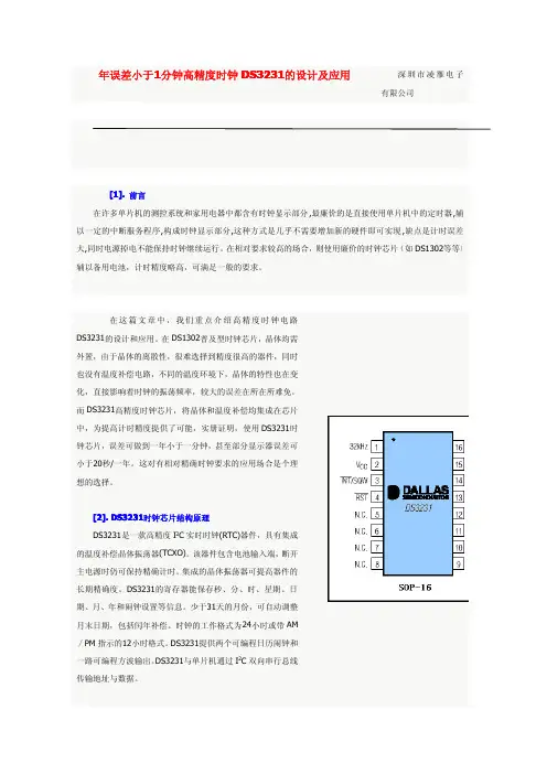
年误差小于1分钟高精度时钟DS3231的设计及应用深圳市凌雁电子有限公司[1].前言在许多单片机的测控系统和家用电器中都含有时钟显示部分,最廉价的是直接使用单片机中的定时器,辅以一定的中断服务程序,构成时钟显示部分,这种方式是几乎不需要增加新的硬件即可实现,缺点是计时误差大,同时电源掉电不能保持时钟继续运行。
在相对要求较高的场合,则使用廉价的时钟芯片(如DS1302等等)辅以备用电池,计时精度略高,可满足一般的要求。
在这篇文章中,我们重点介绍高精度时钟电路DS3231的设计和应用。
在DS1302普及型时钟芯片,晶体均需外置,由于晶体的离散性,很难选择到精度很高的器件,同时也没有温度补偿电路,不同的温度环境下,晶体的特性也在变化,直接影响着时钟的振荡频率,较大的误差在所在所难免。
而DS3231高精度时钟芯片,将晶体和温度补偿均集成在芯片中,为提高计时精度提供了可能,实册证明,使用DS3231时钟芯片,误差可做到一年小于一分钟,甚至部分显示器误差可小于20秒/一年。
这对有相对精确时钟要求的应用场合是个理想的选择。
[2].DS3231时钟芯片结构原理DS3231是一款高精度I2C实时时钟(RTC)器件,具有集成的温度补偿晶体振荡器(TCXO)。
该器件包含电池输入端,断开主电源时仍可保持精确计时。
集成的晶体振荡器可提高器件的长期精确度。
DS3231的寄存器能保存秒、分、时、星期、日期、月、年和闹钟设置等信息。
少于31天的月份,可自动调整月末日期,包括闰年补偿。
时钟的工作格式为24小时或带AM/PM指示的12小时格式。
DS3231提供两个可编程日历闹钟和一路可编程方波输出。
DS3231与单片机通过I2C双向串行总线传输地址与数据。
下图为DS3231典型应用电路,图中可看出,DS3231几乎不需要外部元件。
[3].DS3231时钟芯片结构如图1所示,DS3231的主要组成部分有8个模块,划分为4个功能组:TCXO、电源控制、按钮复位和RTC。
Maxim的几款实时时钟(RTC)芯片
本文介绍了Maxim 的几款实时时钟(RTC)芯片,列出了
DS3231、DS3232、DS3234、DS32B35 和DS32C35 之间的性能差异,以帮助用户找到最合适的解决方案。
重点讨论了DS2131M 内置微机电系统(MEMS)谐
振电路的时钟方案,用于替换晶振方案。
Maxim 是实时时钟(RTC)产品的引领者,已经设计了多款在市场上炙手可热
的实时时钟产品。
这些产品提供完全集成的高精度、温度补偿RTC 方案。
多
数情况下,RTC 的精度主要取决于晶振频率随温度的变化。
因此,对晶体进行
高精度的温度补偿能够提高这些器件的时钟精度。
本文列出了几款RTC (DS3231、DS3232、DS3234、DS32B35 和DS32C35)的性能差异,帮助用户查找合适的器件。
本还重点讨论了内置MEMS 谐振器的
DS3231M,用于替代晶振方案。
DS3231
DS3231 是一款精密的I?C 接口实时时钟,集成了温度补偿晶体振荡器(TCXO)和晶体,以下列出了这款器件的关键参数:
0°C 至+40°C 范围具有±2ppm 精度
-40°C 至+85°C 范围具有±3.5ppm 精度
电池备份输入用于支持连续计时
工作温度范围:
商业级:0°C 至+70°C
工业级:-40°C 至+85°C
低功耗
RTC 提供秒、分钟、小时、星期、日期、月、年计时,并具有闰年补偿,有。
Maxim 的几款实时时钟(RTC)芯片
摘要:本文介绍了Maxim 的几款实时时钟(RTC)芯片,列出了DS3231、DS3232、DS3234、DS32B35 和DS32C35 之间的性能差异,以帮助用户找到最合适的解决方案。
重点讨论了DS2131M 内置微机电系统(MEMS)谐振电路
的时钟方案,用于替换晶振方案。
Maxim 是实时时钟(RTC)产品的引领者,已经设计了多款在市场上炙手可
热的实时时钟产品。
这些产品提供完全集成的高精度、温度补偿RTC 方案。
多数情况下,RTC 的精度主要取决于晶振频率随温度的变化。
因此,对晶体
进行高精度的温度补偿能够提高这些器件的时钟精度。
本文列出了几款RTC (DS3231、DS3232、DS3234、DS32B35 和DS32C35)的性能差异,帮助用户查找合适的器件。
本还重点讨论了内置MEMS 谐振器的DS3231M,用于替代晶振方案。
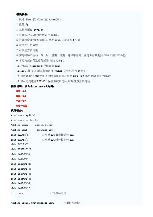
模块参数:1.尺寸:38mm(长)*22mm(宽)*14mm(高)2.重量:8g3.工作电压:3.3--5.5V4.时钟芯片:高精度时钟芯片DS32315.时钟精度:0-40℃范围内,精度2ppm,年误差约1分钟6.带2个日历闹钟7.可编程方波输出8.实时时钟产生秒、分、时、星期、日期、月和年计时,并提供有效期到2100年的闰年补偿9.芯片内部自带温度传感器,精度为±3℃10.存储芯片:AT24C32(存储容量32K)11.IIC总线接口,最高传输速度400KHz(工作电压为5V时)12.可级联其它IIC设备,24C32地址可通过短路A0/A1/A2修改,默认地址为0x5713.带可充电电池LIR2032,保证系统断电后,时钟任然正常走动接线说明,以Arduino uno r3为例:SCL→A5SDA→A4VCC→5VGND→GND代码部分:#include <reg51.h>#include <intrins.h>#define uchar unsigned char#define uint unsigned intsbit SDA=P3^6; //模拟I2C数据传送位SDAsbit SCL=P3^7; //模拟I2C时钟控制位SCLsbit INT=P3^2;sbit RESET=P3^3;sbit led0=P1^0;sbit led1=P1^1;sbit led2=P1^2;sbit led3=P1^3;sbit led4=P1^4;sbit led5=P1^5;sbit led6=P1^6;sbit led7=P1^7;bit ack; //应答标志位#define DS3231_WriteAddress 0xD0 //器件写地址#define DS3231_ReadAddress 0xD1 //器件读地址#define DS3231_SECOND 0x00 //秒#define DS3231_MINUTE 0x01 //分#define DS3231_HOUR 0x02 //时#define DS3231_WEEK 0x03 //星期#define DS3231_DAY 0x04 //日#define DS3231_MONTH 0x05 //月#define DS3231_YEAR 0x06 //年//闹铃1#define DS3231_SALARM1ECOND 0x07 //秒#define DS3231_ALARM1MINUTE 0x08 //分#define DS3231_ALARM1HOUR 0x09 //时#define DS3231_ALARM1WEEK 0x0A //星期/日//闹铃2#define DS3231_ALARM2MINUTE 0x0b //分#define DS3231_ALARM2HOUR 0x0c //时#define DS3231_ALARM2WEEK 0x0d //星期/日#define DS3231_CONTROL 0x0e //控制寄存器#define DS3231_STATUS 0x0f //状态寄存器#define BSY 2 //忙#define OSF 7 //振荡器停止标志#define DS3231_XTAL 0x10 //晶体老化寄存器#define DS3231_TEMPERATUREH 0x11 //温度寄存器高字节(8位)#define DS3231_TEMPERATUREL 0x12 //温度寄存器低字节(高2位)uchar code dis_code[11]={0xc0,0xf9,0xa4,0xb0, // 0,1,2,30x99,0x92,0x82,0xf8,0x80,0x90, 0xff}; // 4,5,6,7,8,9,off uchar data dis_buf[8];uchar data dis_index;uchar data dis_digit;uchar BCD2HEX(uchar val) //BCD转换为Byte{uchar temp;temp=val&0x0f;val>>=4;val&=0x0f;val*=10;temp+=val;return temp;uchar HEX2BCD(uchar val) //B码转换为BCD码{uchar i,j,k;i=val/10;j=val;k=j+(i<<4);return k;}void delayus(uint us){while (us--);}void Start_I2C(){SDA=1; //发送起始条件的数据信号delayus(1);SCL=1;delayus(5); //起始条件建立时间大于4.7us,延时SDA=0; //发送起始信号delayus(5); // 起始条件锁定时间大于4μsSCL=0; //钳住I2C总线,准备发送或接收数据 delayus(2);}void Stop_I2C(){SDA=0; //发送结束条件的数据信号delayus(1); //发送结束条件的时钟信号SCL=1; //结束条件建立时间大于4usdelayus(5);SDA=1; //发送I2C总线结束信号delayus(4);}void SendByte(uchar c){uchar BitCnt;for(BitCnt=0;BitCnt<8;BitCnt++) //要传送的数据长度为8位{if((c<<BitCnt)&0x80)SDA=1; //判断发送位 elseSDA=0;delayus(1);SCL=1; //置时钟线为高,通知被控器开始接收数据位delayus(5); //保证时钟高电平周期大于4μsSCL=0;}delayus(2);SDA=1; //8位发送完后释放数据线,准备接收应答位delayus(2);SCL=1;delayus(3);if(SDA==1)ack=0;elseack=1; //判断是否接收到应答信号SCL=0;delayus(2);}uchar RcvByte(){uchar retc;uchar BitCnt;retc=0;SDA=1; //置数据线为输入方式for(BitCnt=0;BitCnt<8;BitCnt++){delayus(1);SCL=0; //置时钟线为低,准备接收数据位delayus(5); //时钟低电平周期大于4.7μsSCL=1; //置时钟线为高使数据线上数据有效delayus(3);retc=retc<<1;if(SDA==1)retc=retc+1; //读数据位,接收的数据位放入retc中 delayus(2);}SCL=0;delayus(2);return(retc);}void Ack_I2C(bit a){if(a==0)SDA=0; //在此发出应答或非应答信号elseSDA=1;delayus(3);SCL=1;delayus(5); //时钟低电平周期大于4μsSCL=0; //清时钟线,钳住I2C总线以便继续接收delayus(2);}uchar write_byte(uchar addr, uchar write_data){Start_I2C();SendByte(DS3231_WriteAddress);if (ack == 0)return 0;SendByte(addr);if (ack == 0)return 0;SendByte(write_data);if (ack == 0)return 0;Stop_I2C();delayus(10);return 1;}uchar read_current(){uchar read_data;Start_I2C();SendByte(DS3231_ReadAddress);if(ack==0)return(0);read_data = RcvByte();Ack_I2C(1);Stop_I2C();return read_data;}uchar read_random(uchar random_addr) {Start_I2C();SendByte(DS3231_WriteAddress);if(ack==0)return(0);SendByte(random_addr);if(ack==0)return(0);return(read_current());}void ModifyTime(uchar yea,uchar mon,uchar da,uchar hou,uchar min,uchar sec){uchar temp=0;temp=HEX2BCD(yea);write_byte(DS3231_YEAR,temp); //修改年temp=HEX2BCD(mon);write_byte(DS3231_MONTH,temp); //修改月temp=HEX2BCD(da);write_byte(DS3231_DAY,temp); //修改日temp=HEX2BCD(hou);write_byte(DS3231_HOUR,temp); //修改时temp=HEX2BCD(min);write_byte(DS3231_MINUTE,temp); //修改分temp=HEX2BCD(sec);write_byte(DS3231_SECOND,temp); //修改秒}void TimeDisplay(uchar Dhour,uchar Dmin,uchar Dsec){dis_buf[7]=dis_code[Dhour / 10]; // 时十位dis_buf[6]=dis_code[Dhour % 10]; // 时个位dis_buf[4]=dis_code[Dmin / 10]; // 分十位dis_buf[3]=dis_code[Dmin % 10]; // 分个位dis_buf[1]=dis_code[Dsec / 10]; // 秒十位dis_buf[0]=dis_code[Dsec % 10]; // 秒个位dis_buf[2]=0xbf; // 显示"-"dis_buf[5]=0xbf;}void DateDisplay(uchar Dyear,uchar Dmonth,uchar Dday){dis_buf[7]=dis_code[Dyear / 10]; // 年十位dis_buf[6]=dis_code[Dyear % 10]; // 年个位dis_buf[4]=dis_code[Dmonth / 10]; // 月十位dis_buf[3]=dis_code[Dmonth % 10]; // 月个位dis_buf[1]=dis_code[Dday / 10]; // 天十位dis_buf[0]=dis_code[Dday % 10]; // 天个位dis_buf[2]=0xbf; // 显示"-"dis_buf[5]=0xbf;}void get_show_time(void){uchar Htemp1,Htemp2,Mtemp1,Mtemp2,Stemp1,Stemp2;Htemp1=read_random(DS3231_HOUR); //时 24小时制Htemp1&=0x3f;Htemp2=BCD2HEX(Htemp1);Mtemp1=read_random(DS3231_MINUTE); //分Mtemp2=BCD2HEX(Mtemp1);Stemp1=read_random(DS3231_SECOND); //秒Stemp2=BCD2HEX(Stemp1);TimeDisplay(Htemp2,Mtemp2,Stemp2);}void get_show_date(void){uchar Ytemp1,Ytemp2,Mtemp1,Mtemp2,Dtemp1,Dtemp2;Ytemp1=read_random(DS3231_YEAR); //年Ytemp2=BCD2HEX(Ytemp1);Mtemp1=read_random(DS3231_MONTH); //月Mtemp2=BCD2HEX(Mtemp1);Dtemp1=read_random(DS3231_DAY); //日Dtemp2=BCD2HEX(Dtemp1);DateDisplay(Ytemp2,Mtemp2,Dtemp2);}void get_show_Temperature(void){uchar Ttemp1,Ttemp2,Ttemp3,Ttemp4;Ttemp1=read_random(DS3231_TEMPERATUREH); //温度高字节Ttemp2=BCD2HEX(Ttemp1);Ttemp3=read_random(DS3231_TEMPERATUREL); //温度低字节Ttemp4=BCD2HEX(Ttemp3);DateDisplay(0,Ttemp2,Ttemp4);}void timer0() interrupt 1{TH0=0xFC;TL0=0x17;P2=0xff; // 先关闭所有数码管P0=dis_buf[dis_index]; // 显示代码传送到P0口P2=dis_digit;if (dis_digit & 0x80)dis_digit=(dis_digit << 1) | 0x1;elsedis_digit=(dis_digit << 1);dis_index++;dis_index&=0x07; // 8个数码管全部扫描完一遍之后,再回到第一个开始下一次扫描}void main(){uint ii = 0;RESET=0x1; //DS3231复位操作,正常操作下不需要每次都复位delayus(5000);led0=0;led1=0;led2=0;led3=0;led4=0;P0=0xff;P2=0xff;dis_digit=0xfe;dis_index=0;TimeDisplay(12, 5, 18);TMOD=0x11; // 定时器0, 1工作模式1, 16位定时方式TH0=0xFC;TL0=0x17;TCON=0x01;IE=0x82; // 使能timer0,1 中断TR0=1;if (write_byte(DS3231_CONTROL, 0x1C) == 0)led0=1;if (write_byte(DS3231_STATUS, 0x00) == 0)led1=1;ModifyTime(10,6,13,15,30,00); //初始化时钟,2010/6/13,15/30/00//小时采用24小时制while(1){//get_show_date(); //显示日期//get_show_Temperature(); //显示温度get_show_time(); //显示时间delayus(50000);} }。
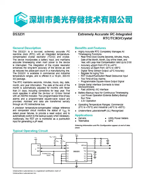
General DescriptionThe DS3231 is a low-cost, extremely accurate I 2C real-time clock (RTC) with an integrated temperature-compensated crystal oscillator (TCXO) and crystal. The device incorporates a battery input, and maintains accurate timekeeping when main power to the device is interrupted. The integration of the crystal resonator enhances the long-term accuracy of the device as well as reduces the piece-part count in a manufacturing line. The DS3231 is available in commercial and industrial temperature ranges, and is offered in a 16-pin, 300-mil SO package.The RTC maintains seconds, minutes, hours, day, date, month, and year information. The date at the end of the month is automatically adjusted for months with fewer than 31 days, including corrections for leap year. The clock operates in either the 24-hour or 12-hour format with an AM /PM indicator. Two programmable time-of-day alarms and a programmable square-wave output are provided. Address and data are transferred serially through an I 2C bidirectional bus.A precision temperature-compensated voltage reference and comparator circuit monitors the status of V CC to detect power failures, to provide a reset output, and to automatically switch to the backup supply when necessary. Additionally, the RST pin is monitored as a pushbutton input for generating a μP reset.Benefits and Features●Highly Accurate RTC Completely Manages AllTimekeeping Functions•Real-Time Clock Counts Seconds, Minutes, Hours,Date of the Month, Month, Day of the Week, and Year, with Leap-Year Compensation Valid Up to 2100•Accuracy ±2ppm from 0°C to +40°C •Accuracy ±3.5ppm from -40°C to +85°C •Digital Temp Sensor Output: ±3°C Accuracy •Register for Aging Trim•RST Output/Pushbutton Reset Debounce Input •Two Time-of-Day Alarms•Programmable Square-Wave Output Signal ●Simple Serial Interface Connects to MostMicrocontrollers•Fast (400kHz) I 2C Interface●Battery-Backup Input for Continuous Timekeeping•Low Power Operation Extends Battery-Backup Run Time• 3.3V Operation ●Operating Temperature Ranges: Commercial(0°C to +70°C) and Industrial (-40°C to +85°C)●Underwriters Laboratories ® (UL) Recognized ApplicationsUnderwriters Laboratories is a registered certification mark of Underwriters Laboratories Inc.Ordering Information and Pin Configuration appear at end of data sheet.●Servers ●Telematics●Utility Power Meters ●GPSDS3231Extremely Accurate I 2C-IntegratedRTC/TCXO/Crystalto the DS3231 resets because of a loss of V CC or other event, it is possible that the microcontroller and DS3231 I 2C communications could become unsynchronized, e.g., the microcontroller resets while reading data from the DS3231. When the microcontroller resets, the DS3231 I 2C interface may be placed into a known state by tog-gling SCL until SDA is observed to be at a high level. At that point the microcontroller should pull SDA low while SCL is high, generating a START condition.Clock and CalendarThe time and calendar information is obtained by reading the appropriate register bytes. Figure 1 illustrates the RTC registers. The time and calendar data are set or initialized by writing the appropriate register bytes. The contents of the time and calendar registers are in the binary-codedNote: Unless otherwise specified, the registers’ state is not defined when power is first applied.Figure 1. Timekeeping RegistersADDRESSBIT 7MSB BIT 6BIT 5BIT 4BIT 3BIT 2BIT 1BIT 0LSBFUNCTION RANGE 00h 010 Seconds Seconds Seconds 00–5901h 010 Minutes MinutesMinutes 00–5902h 012/24AM /PM 10 HourHourHours1–12 + AM /PM00–2320 Hour03h 000DayDay 1–704h 0010 DateDate Date 01–3105h Century10 MonthMonth Month/Century 01–12 + Century06h 10 YearYear Year 00–9907h A1M110 Seconds Seconds Alarm 1 Seconds 00–5908h A1M210 Minutes Minutes Alarm 1 Minutes 00–5909h A1M312/24AM /PM 10 HourHour Alarm 1 Hours 1–12 + AM /PM00–2320 Hour0Ah A1M4DY/DT10 DateDay Alarm 1 Day 1–7Date Alarm 1 Date 1–310Bh A2M210 Minutes MinutesAlarm 2 Minutes 00–590Ch A2M312/24AM /PM 10 HourHour Alarm 2 Hours 1–12 + AM /PM00–2320 Hour0Dh A2M4DY/DT 10 Date Day Alarm 2 Day 1–7DateAlarm 2 Date 1–310Eh EOSC BBSQWCONV RS2RS1INTCN A2IE A1IE Control —0Fh OSF 000EN32kHz BSY A2F A1F Control/Status —10h SIGN DATA DATA DATA DATA DATA DATA DATA Aging Offset —11h SIGN DATA DATA DATA DATA DATA DATA DATA MSB of Temp —12hDATADATA 0LSB of Temp—RTC/TCXO/CrystalAddress MapFigure 1 shows the address map for the DS3231 time-keeping registers. During a multibyte access, when the address pointer reaches the end of the register space (12h), it wraps around to location 00h. On an I 2C START or address pointer incrementing to location 00h, the cur-rent time is transferred to a second set of registers. The time information is read from these secondary registers, while the clock may continue to run. This eliminates the need to reread the registers in case the main registers update during a read.I 2C InterfaceThe I 2C interface is accessible whenever either V CC or V BAT is at a valid level. If a microcontroller connecteddecimal (BCD) format. The DS3231 can be run in either 12-hour or 24-hour mode. Bit 6 of the hours register is defined as the 12- or 24-hour mode select bit. When high, the 12-hour mode is selected. In the 12-hour mode, bit 5 is the AM/PM bit with logic-high being PM. In the 24-hour mode, bit 5 is the 20-hour bit (20–23 hours). The century bit (bit 7 of the month register) is toggled when the years register overflows from 99 to 00.The day-of-week register increments at midnight. Values that correspond to the day of week are user-defined but must be sequential (i.e., if 1 equals Sunday, then 2 equals Monday, and so on). Illogical time and date entries result in undefined operation.When reading or writing the time and date registers, sec-ondary (user) buffers are used to prevent errors when the internal registers update. When reading the time and date registers, the user buffers are synchronized to the internal registers on any START and when the register pointer rolls over to zero. The time information is read from these secondary registers, while the clock continues to run. This eliminates the need to reread the registers in case the main registers update during a read.The countdown chain is reset whenever the seconds register is written. Write transfers occur on the acknowl-edge from the DS3231. Once the countdown chain is reset, to avoid rollover issues the remaining time and date registers must be written within 1 second. The 1Hz square-wave output, if enabled, transitions high 500ms after the seconds data transfer, provided the oscillator is already running.AlarmsThe DS3231 contains two time-of-day/date alarms. Alarm 1 can be set by writing to registers 07h to 0Ah. Alarm 2 can be set by writing to registers 0Bh to 0Dh. The alarms can be programmed (by the alarm enable and INTCN bits of the control register) to activate the INT/SQW output on an alarm match condition. Bit 7 of each of the time-of-day/date alarm registers are mask bits (Table 2). When all the mask bits for each alarm are logic 0, an alarm only occurs when the values in the timekeeping registers match the corresponding val-ues stored in the time-of-day/date alarm registers. The alarms can also be programmed to repeat every second, minute, hour, day, or date. Table 2 shows the possible settings. Configurations not listed in the table will result in illogical operation.The DY/DT bits (bit 6 of the alarm day/date registers) control whether the alarm value stored in bits 0 to 5 of that register reflects the day of the week or the date of the month. If DY/DT is written to logic 0, the alarm will be the result of a match with date of the month. If DY/DT is written to logic 1, the alarm will be the result of a match with day of the week.When the RTC register values match alarm register set-tings, the corresponding Alarm Flag ‘A1F’ or ‘A2F’ bit is set to logic 1. If the corresponding Alarm Interrupt Enable ‘A1IE’ or ‘A2IE’ is also set to logic 1 and the INTCN bit is set to logic 1, the alarm condition will activate the INT/SQW signal. The match is tested on the once-per-second update of the time and date registers.Table 2. Alarm Mask BitsDY/DTALARM 1 REGISTER MASK BITS (BIT 7)ALARM RATE A1M4A1M3A1M2A1M1X1111Alarm once per secondX1110Alarm when seconds matchX1100Alarm when minutes and seconds matchX1000Alarm when hours, minutes, and seconds match 00000Alarm when date, hours, minutes, and seconds match 10000Alarm when day, hours, minutes, and seconds matchDY/DT ALARM 2 REGISTER MASK BITS (BIT 7)ALARM RATE A2M4A2M3A2M2X111Alarm once per minute (00 seconds of every minute)X110Alarm when minutes matchX100Alarm when hours and minutes match0000Alarm when date, hours, and minutes match1000Alarm when day, hours, and minutes matchRTC/TCXO/Crystaling an acknowledge bit on the last byte that has been clocked out of the slave. In this case, the slave must leave the data line high to enable the master to gener-ate the STOP condition.Figures 3 and 4 detail how data transfer is accomplished on the I 2C bus. Depending upon the state of the R/W bit, two types of data transfer are possible:Data transfer from a master transmitter to a slave receiver. The first byte transmitted by the masteris the slave address. Next follows a number of data bytes. The slave returns an acknowledge bit after each received byte. Data is transferred with the most signifi-cant bit (MSB) first.Data transfer from a slave transmitter to a master receiver. The first byte (the slave address) is transmit-ted by the master. The slave then returns an acknowl-edge bit. Next follows a number of data bytes transmit-ted by the slave to the master. The master returns an acknowledge bit after all received bytes other than theFigure 2. IC Data Transfer OverviewFigure 3. Data Write—Slave Receiver ModeFigure 4. Data Read—Slave Transmitter ModeRTC/TCXO/CrystalRTC/TCXO/CrystalFigure 5. Data Write/Read (Write Pointer, Then Read)—Slave Receive and Transmit。
General DescriptionThe DS3231 is a low-cost, extremely accurate I 2C real-time clock (RTC) with an integrated temperature-compensated crystal oscillator (TCXO) and crystal. The device incorporates a battery input, and maintains accurate timekeeping when main power to the device is interrupted. The integration of the crystal resonator enhances the long-term accuracy of the device as well as reduces the piece-part count in a manufacturing line. The DS3231 is available in commercial and industrial temperature ranges, and is offered in a 16-pin, 300-mil SO package.The RTC maintains seconds, minutes, hours, day, date, month, and year information. The date at the end of the month is automatically adjusted for months with fewer than 31 days, including corrections for leap year. The clock operates in either the 24-hour or 12-hour format with an AM /PM indicator. Two programmable time-of-day alarms and a programmable square-wave output are provided. Address and data are transferred serially through an I 2C bidirectional bus.A precision temperature-compensated voltage reference and comparator circuit monitors the status of V CC to detect power failures, to provide a reset output, and to automatically switch to the backup supply when necessary. Additionally, the RST pin is monitored as a pushbutton input for generating a μP reset.Benefits and Features●Highly Accurate RTC Completely Manages AllTimekeeping Functions•Real-Time Clock Counts Seconds, Minutes, Hours,Date of the Month, Month, Day of the Week, and Year, with Leap-Year Compensation Valid Up to 2100•Accuracy ±2ppm from 0°C to +40°C •Accuracy ±3.5ppm from -40°C to +85°C •Digital Temp Sensor Output: ±3°C Accuracy •Register for Aging Trim•RST Output/Pushbutton Reset Debounce Input •Two Time-of-Day Alarms•Programmable Square-Wave Output Signal ●Simple Serial Interface Connects to MostMicrocontrollers•Fast (400kHz) I 2C Interface●Battery-Backup Input for Continuous Timekeeping•Low Power Operation Extends Battery-Backup Run Time• 3.3V Operation ●Operating Temperature Ranges: Commercial(0°C to +70°C) and Industrial (-40°C to +85°C)●Underwriters Laboratories ® (UL) Recognized ApplicationsUnderwriters Laboratories is a registered certification mark of Underwriters Laboratories Inc.Ordering Information and Pin Configuration appear at end of data sheet.●Servers ●Telematics●Utility Power Meters ●GPSDS3231Extremely Accurate I 2C-IntegratedRTC/TCXO/Crystalto the DS3231 resets because of a loss of V CC or other event, it is possible that the microcontroller and DS3231 I 2C communications could become unsynchronized, e.g., the microcontroller resets while reading data from the DS3231. When the microcontroller resets, the DS3231 I 2C interface may be placed into a known state by tog-gling SCL until SDA is observed to be at a high level. At that point the microcontroller should pull SDA low while SCL is high, generating a START condition.Clock and CalendarThe time and calendar information is obtained by reading the appropriate register bytes. Figure 1 illustrates the RTC registers. The time and calendar data are set or initialized by writing the appropriate register bytes. The contents of the time and calendar registers are in the binary-codedNote: Unless otherwise specified, the registers’ state is not defined when power is first applied.Figure 1. Timekeeping RegistersADDRESSBIT 7MSB BIT 6BIT 5BIT 4BIT 3BIT 2BIT 1BIT 0LSBFUNCTION RANGE 00h 010 Seconds Seconds Seconds 00–5901h 010 Minutes MinutesMinutes 00–5902h 012/24AM /PM 10 HourHourHours1–12 + AM /PM00–2320 Hour03h 000DayDay 1–704h 0010 DateDate Date 01–3105h Century10 MonthMonth Month/Century 01–12 + Century06h 10 YearYear Year 00–9907h A1M110 Seconds Seconds Alarm 1 Seconds 00–5908h A1M210 Minutes Minutes Alarm 1 Minutes 00–5909h A1M312/24AM /PM 10 HourHour Alarm 1 Hours 1–12 + AM /PM00–2320 Hour0Ah A1M4DY/DT10 DateDay Alarm 1 Day 1–7Date Alarm 1 Date 1–310Bh A2M210 Minutes MinutesAlarm 2 Minutes 00–590Ch A2M312/24AM /PM 10 HourHour Alarm 2 Hours 1–12 + AM /PM00–2320 Hour0Dh A2M4DY/DT 10 Date Day Alarm 2 Day 1–7DateAlarm 2 Date 1–310Eh EOSC BBSQWCONV RS2RS1INTCN A2IE A1IE Control —0Fh OSF 000EN32kHz BSY A2F A1F Control/Status —10h SIGN DATA DATA DATA DATA DATA DATA DATA Aging Offset —11h SIGN DATA DATA DATA DATA DATA DATA DATA MSB of Temp —12hDATADATA 0LSB of Temp—RTC/TCXO/CrystalAddress MapFigure 1 shows the address map for the DS3231 time-keeping registers. During a multibyte access, when the address pointer reaches the end of the register space (12h), it wraps around to location 00h. On an I 2C START or address pointer incrementing to location 00h, the cur-rent time is transferred to a second set of registers. The time information is read from these secondary registers, while the clock may continue to run. This eliminates the need to reread the registers in case the main registers update during a read.I 2C InterfaceThe I 2C interface is accessible whenever either V CC or V BAT is at a valid level. If a microcontroller connecteddecimal (BCD) format. The DS3231 can be run in either 12-hour or 24-hour mode. Bit 6 of the hours register is defined as the 12- or 24-hour mode select bit. When high, the 12-hour mode is selected. In the 12-hour mode, bit 5 is the AM/PM bit with logic-high being PM. In the 24-hour mode, bit 5 is the 20-hour bit (20–23 hours). The century bit (bit 7 of the month register) is toggled when the years register overflows from 99 to 00.The day-of-week register increments at midnight. Values that correspond to the day of week are user-defined but must be sequential (i.e., if 1 equals Sunday, then 2 equals Monday, and so on). Illogical time and date entries result in undefined operation.When reading or writing the time and date registers, sec-ondary (user) buffers are used to prevent errors when the internal registers update. When reading the time and date registers, the user buffers are synchronized to the internal registers on any START and when the register pointer rolls over to zero. The time information is read from these secondary registers, while the clock continues to run. This eliminates the need to reread the registers in case the main registers update during a read.The countdown chain is reset whenever the seconds register is written. Write transfers occur on the acknowl-edge from the DS3231. Once the countdown chain is reset, to avoid rollover issues the remaining time and date registers must be written within 1 second. The 1Hz square-wave output, if enabled, transitions high 500ms after the seconds data transfer, provided the oscillator is already running.AlarmsThe DS3231 contains two time-of-day/date alarms. Alarm 1 can be set by writing to registers 07h to 0Ah. Alarm 2 can be set by writing to registers 0Bh to 0Dh. The alarms can be programmed (by the alarm enable and INTCN bits of the control register) to activate the INT/SQW output on an alarm match condition. Bit 7 of each of the time-of-day/date alarm registers are mask bits (Table 2). When all the mask bits for each alarm are logic 0, an alarm only occurs when the values in the timekeeping registers match the corresponding val-ues stored in the time-of-day/date alarm registers. The alarms can also be programmed to repeat every second, minute, hour, day, or date. Table 2 shows the possible settings. Configurations not listed in the table will result in illogical operation.The DY/DT bits (bit 6 of the alarm day/date registers) control whether the alarm value stored in bits 0 to 5 of that register reflects the day of the week or the date of the month. If DY/DT is written to logic 0, the alarm will be the result of a match with date of the month. If DY/DT is written to logic 1, the alarm will be the result of a match with day of the week.When the RTC register values match alarm register set-tings, the corresponding Alarm Flag ‘A1F’ or ‘A2F’ bit is set to logic 1. If the corresponding Alarm Interrupt Enable ‘A1IE’ or ‘A2IE’ is also set to logic 1 and the INTCN bit is set to logic 1, the alarm condition will activate the INT/SQW signal. The match is tested on the once-per-second update of the time and date registers.Table 2. Alarm Mask BitsDY/DTALARM 1 REGISTER MASK BITS (BIT 7)ALARM RATE A1M4A1M3A1M2A1M1X1111Alarm once per secondX1110Alarm when seconds matchX1100Alarm when minutes and seconds matchX1000Alarm when hours, minutes, and seconds match 00000Alarm when date, hours, minutes, and seconds match 10000Alarm when day, hours, minutes, and seconds matchDY/DT ALARM 2 REGISTER MASK BITS (BIT 7)ALARM RATE A2M4A2M3A2M2X111Alarm once per minute (00 seconds of every minute)X110Alarm when minutes matchX100Alarm when hours and minutes match0000Alarm when date, hours, and minutes match1000Alarm when day, hours, and minutes matchRTC/TCXO/Crystaling an acknowledge bit on the last byte that has been clocked out of the slave. In this case, the slave must leave the data line high to enable the master to gener-ate the STOP condition.Figures 3 and 4 detail how data transfer is accomplished on the I 2C bus. Depending upon the state of the R/W bit, two types of data transfer are possible:Data transfer from a master transmitter to a slave receiver. The first byte transmitted by the masteris the slave address. Next follows a number of data bytes. The slave returns an acknowledge bit after each received byte. Data is transferred with the most signifi-cant bit (MSB) first.Data transfer from a slave transmitter to a master receiver. The first byte (the slave address) is transmit-ted by the master. The slave then returns an acknowl-edge bit. Next follows a number of data bytes transmit-ted by the slave to the master. The master returns an acknowledge bit after all received bytes other than theFigure 2. IC Data Transfer OverviewFigure 3. Data Write—Slave Receiver ModeFigure 4. Data Read—Slave Transmitter ModeRTC/TCXO/CrystalRTC/TCXO/CrystalFigure 5. Data Write/Read (Write Pointer, Then Read)—Slave Receive and Transmit。
//DS3231,经测试,日期,时间,星期,温度可以用1602显示#in elude <reg51.h>#in elude vintrin s.h>#defi ne uchar un sig ned char#defi ne uint un sig ned int#define yh 0x80 //第一行的初始位置#defi ne er 0x80+0x40 // 第二行初始位置sbit wr=P1A1;sbit rs=P1A。
;sbit en=卩2人5;sbit SDA=P3A6; //模拟I2C数据传送位 SDAsbit SCL=P3A7; //模拟I2C时钟控制位 SCL sbit INT=P3A2;sbit key1=P1A7; // 功能键,修改键sbitkey2=P3A4;// 上调键sbitkey3=P3A5;// 下调键sbit RESET=P3A3;bit ack;// 应答标志位#define DS3231 _WriteAddress 0xD0 // 器件写地址#define DS3231 _ReadAddress 0xD1// 器件读地址#define DS3231_SECOND 0x00 // 秒#define DS3231 _MINUTE 0x01 // 分#define DS3231 _HOUR 0x02 // 时#define DS3231 _WEEK 0x03 // 星期#define DS3231 _DAY 0x04 // 日#define DS3231_MONTH 0x05 // 月#define DS3231 _YEAR 0x06 // 年// 闹铃 1#define DS3231 _SALARM1ECOND 0x07 // 秒#define DS3231 _ALARM1MINUTE 0x08 // 分#define DS3231 _ALARM1HOUR 0x09 // 时#define DS3231 _ALARM1WEEK 0x0A// 星期 / 日// 闹铃 2#define DS3231 _ALARM2MINUTE 0x0b // 分#define DS3231 _ALARM2HOUR0x0c // 时可编辑#define DS3231_TEMPERATUREH 0x11#define DS3231_TEMPERATUREL 0x12 uchara,miao,shi,fen,ri,yue,nian,week,temp1,temp2,key1n,temp; uchar code tab1[]={"2017- - FRI"}; uchar code tab2[]={" : : ."};uchar HEX2BCD(uchar val) //B 码转换为 BCD 码{uchar k;k=(val)/10*16+(val)%10; return k;}uchar BCD_Decimal(uchar bcd){uchar Decimal; Decimal=bcd>>4;return(Decimal=Decimal*10+(bcd&=0x0F));#define DS3231_ALARM2WEEK #define DS3231_CONTROL #define DS3231_STATUS #define BSY #define OSF0x0d // 星期 / 日0x0e // 控制寄存器 0x0f // 状态寄存器2 // 忙7// 振荡器停止标志#define DS3231_XTAL0x10 // 晶体老化寄存器// 温度寄存器高字节 // 温度寄存器低字节 (8 位 ) (高 2 位 )}void delayus(uint us){while (us--);}void Start_I2C(){SDA=1; // 发送起始条件的数据信号 delayus(1);SCL=1;delayus(5); // 起始条件建立时间大于 4.7us, 延时SDA=0; // 发送起始信号delayus(5); //起始条件锁定时间大于4阳SCL=0; //钳住 I2C 总线,准备发送或接收数据delayus(2);}void Stop_I2C(){SDA=0; // 发送结束条件的数据信号delayus(1); // 发送结束条件的时钟信号SCL=1; // 结束条件建立时间大于 4us delayus(5);SDA=1; // 发送 I2C 总线结束信号delayus(4);}void SendByte(uchar c){uchar BitCnt;for(BitCnt=0;BitCnt<8;BitCnt ++){if((c<<BitCnt)&0x80)SDA=1;elseSDA=0;delayus(1);SCL=1;数据位delayus(5);SCL=0;// 要传送的数据长度为 8 位// 判断发送位// 置时钟线为高,通知被控器开始接收//保证时钟咼电平周期大于 4阳delayus(2);SDA=1; //8 位发送完后释放数据线,准备接收应答位delayus(2);SCL=1;delayus(3);if(SDA==1)ack=0;elseack=1; // 判断是否接收到应答信号SCL=0;delayus(2);}uchar RcvByte(){uchar retc;uchar BitCnt;retc=0;SDA=1; // 置数据线为输入方式for(BitCnt=0;BitCnt<8;BitCnt++)SCL=0;delayus(5);SCL=1;delayus(3);retc=retc<<1;if(SDA==1)retc=retc+1;delayus(2);}SCL=0;delayus(2);return(retc);}// 置时钟线为低,准备接收数据位//时钟低电平周期大于 4.7 Q//置时钟线为高使数据线上数据有效// 读数据位 ,接收的数据位放入 retc 中void Ack_I2C(bit a){if(a==0)SDA=0; else // 在此发出应答或非应答信号SDA=1;SCL=1;delayus(5); //时钟低电平周期大于4阴SCL=0; // 清时钟线,钳住 I2C 总线以便继续接收delayus(2);}uchar write_byte(uchar addr, uchar write_data) {Start_I2C();SendByte(DS3231_WriteAddress);if (ack == 0)return 0;SendByte(addr);if (ack == 0)return 0;SendByte(write_data);if (ack == 0)return 0;Stop_I2C();return 1;}uchar read_current(){uchar read_data;Start_I2C();SendByte(DS3231_ReadAddress);if(ack==0)return(0);read_data = RcvByte();Ack_I2C(1);Stop_I2C();return read_data;}uchar read_random(uchar random_addr) {Start_I2C();SendByte(DS3231_WriteAddress);if(ack==0)SendByte(random_addr);if(ack==0)return(0);return(read_current()); }void ModifyTime(uchar yea,uchar sec,uchar week){uchar temp=0;temp=HEX2BCD(yea);write_byte(DS3231_YEAR,temp);temp=HEX2BCD(mon);write_byte(DS3231_MONTH,temp);temp=HEX2BCD(da);write_byte(DS3231_DAY,temp);temp=HEX2BCD(hou);write_byte(DS3231_HOUR,temp); mon,uchar da,uchar hou,uchar// 修改年// 修改月// 修改日// 修改时min,uchartemp=HEX2BCD(min);write_byte(DS3231_MINUTE,temp); // 修改分temp=HEX2BCD(sec);write_byte(DS3231_SECOND,temp); // 修改秒temp=HEX2BCD(week);write_byte(DS3231_WEEK,temp); // 修改星期}**************** 液晶写入********************** write_1602com(uchar com)// 液晶写入指令函数{ rs=0;// 置为写入命令P0=com;// 送入数据delayus(1000);en=1;// 拉高使能端delayus(1000);en=0;// 完成高脉冲}write_1602dat(uchar dat){rs=1;// 置为写入数据P0=dat;// 送入数据delayus(1000);en=1;delayus(1000);en=0;}*******************over*********************lcd_init()// 液晶初始化函数{ wr=0;write_1602com(0x38);// 设置液晶工作模式write_1602com(0x0c);// 开显示不显示光标write_1602com(0x06);// 整屏不移动,指针加一write_1602com(0x01);write_1602com(yh+1);// 字符写入的位置for(a=0;a<14;a++){write_1602dat(tab1[a]);//delay(3);}write_1602com(er);for(a=0;a<12;a++){//delay(3);}write_1602com(er+14); // 写温度符号write_1602dat(0xdf);write_1602dat(0x43);void write_sfm(uchar add,uchar dat)// 写时分秒及温度{ uchar gw,sw;gw=dat%10;sw=dat/10;write_1602com(er+add);write_1602dat(0x30+sw);write_1602dat(0x30+gw);}void write_nyr(uchar add,uchar dat) // 写日期{ uchar gw,sw;gw=dat%10;sw=dat/10;write_1602com(yh+add);write_1602dat(0x30+sw);write_1602dat(0x30+gw);}void write_week(uchar week)// 写星期函数{write_1602com(yh+0x0c);switch(week){case 1:write_1602dat('M');//delay(5);write_1602dat('O');//delay(5);write_1602dat('N');break;case 2:write_1602dat('T');//delay(5);write_1602dat('U');//delay(5);write_1602dat('E');break;case 3:write_1602dat('W');//delay(5);break;case 4:write_1602dat('T');//delay(5);write_1602dat('H');//delay(5);write_1602dat('U');break;case 5:write_1602dat('F');//delay(5);write_1602dat('R');//delay(5);write_1602dat('I');break;case 6:write_1602dat('S');//delay(5);write_1602dat('T');//delay(5);write_1602dat('A');break;case 7:write_1602dat('S');//delay(5);write_1602dat('U');//delay(5);write_1602dat('N');break;}void keyscan(){if(key1==0)//key1 为功能键{delayus(5000);if(key1==0){while(!key1);key1n++;if(key1n==9)key1n=1;switch(key1n){case 1: TR0=0;// 关闭定时器//TR1=0;write_1602com(er+0x06);// 写入光标位置write_1602com(0x0f);// 设置光标为闪烁break;//write_1602com(0x0f);break;case 3: write_1602com(er+0);//shi//write_1602com(0x0f);break;case 4: write_1602com(yh+0x0d);//week//write_1602com(0x0f);break;case 5: write_1602com(yh+0x09);//ri//write_1602com(0x0f);break;case 6: write_1602com(yh+0x06);//yue//write_1602com(0x0f);break;case 7: write_1602com(yh+0x03);//nian//write_1602com(0x0f);break;case 8: write_1602com(0x0c);// 设置光标不闪烁write_sfm(6,miao);// 写入新的秒数temp=(miao)/10*16+(miao)%10;write_byte(DS3231_SECOND,temp); // 退出时修改秒write_1602com(er+6);temp=(fen)/10*16+(fen)%10;write_byte(DS3231_MINUTE,temp); // 修改分write_1602com(er+3);TR0=1;// 打开定时器break;}}}if(key1n!=0)// 当 key1 按下以下。
实时时钟DS3231读取信息出错的分析实时时钟芯片DS3231Maxim Integrated新型实时时钟(RTC)DS3231,内部集成了TCXO、RTC和32.768kHz晶体,并采用低成本、标准型、16引脚SOIC封装。
在-40C至+85C温度范围内,计时精度为2分钟/年。
这一出色性能使DS3231成为当前要求高计时精度应用的最佳解决方案。
而RTC的其它集成功能也扩展了系统应用领域,适合那些对计时精度要求极高的应用。
应用包括:服务器、电表、安防及门禁控制系统、车队管理、远程信息处理系统、GPS导航装置、POS终端以及ATM。
除计时精度高之外,DS3231还具有一些其它功能,这些功能扩展了系统主机的附加功能和选择范围。
该器件内部集成了一个非常精确的数字温度传感器,可通过I2C* 接口对其进行访问(如同时间一样)。
这个温度传感器的精度为3C。
片上控制电路可实现自动电源检测,并管理主电源和备用电源(即低压电池)之间的电源切换。
如果主电源掉电,该器件仍可继续提供精确的计时和温度,性能不受影响。
当主电源重新加电或电压值返回到容许范围内时,片上复位功能可用来重新启动系统微处理器。
Device Name Extremely Accurate Real-TIme Clock_TCXO_CrystalPackage Size 16-Pin,300 mil SOICOperaTIng V oltage (V)2.3 to 5.5TImekeeping Accuracy (over temp)3ppm (-40 degrees Celsius to +85 degrees Celsius)1ppm (0 to +40 degrees Celsius)Current ConsumpTIon (A)1.5 (typ); 4.0 (max)在单片机系统设计中,对系统的抗干扰设计、信号完整性设计、时序设计大都能引起关注;但对由于备用电池与系统电源上电或电源切换导致个别芯片的时序不稳定,引起不能正常工作或启动的问题,很多设计者还是认识不清。
DS3231高精度时钟模块程序很想要个时钟模块,自己焊又太麻烦,干脆在TB 上买下来了,省时。
模块参数:1.尺寸:38mm(长)*22mm(宽)*14mm(高)2.重量:8g3.工作电压:3.3--5.5V4.时钟芯片:高精度时钟芯片DS32315.时钟精度:0-40℃范围内,精度2ppm,年误差约1分钟6.带2个日历闹钟7.可编程方波输出8.实时时钟产生秒、分、时、星期、日期、月和年计时,并提供有效期到2100年的闰年补偿9.芯片内部自带温度传感器,精度为±3℃10.存储芯片:AT24C32(存储容量32K)11.IIC总线接口,最高传输速度400KHz(工作电压为5V时)12.可级联其它IIC设备,24C32地址可通过短路A0/A1/A2修改,默认地址为0x5713.带可充电电池LIR2032,保证系统断电后,时钟任然正常走动接线说明,以Arduino uno r3为例:SCL→A5SDA→A4VCC→5VGND→GND代码部分:#include ;#include ;#define ucharunsigned char#define uintunsigned intsbit SDA=P3^6;//模拟I2C数据传送位SDAsbit SCL=P3^7;//模拟I2C时钟控制位SCLsbit INT=P3^2;sbit RESET=P3^3;sbit led0=P1^0;sbit led1=P1^1;sbit led2=P1^2;sbit led3=P1^3;sbit led4=P1^4;sbit led5=P1^5;sbit led6=P1^6;sbit led7=P1^7;bit ack;//应答标志位#define DS3231_WriteAddress 0xD0 //器件写地址#define DS3231_ReadAddress 0xD1 //器件读地址#define DS3231_SECOND0x00//秒#define DS3231_MINUTE0x01//分#define DS3231_HOUR0x02//时#define DS3231_WEEK0x03//星期#define DS3231_DAY0x04//日#define DS3231_MONTH0x05//月#define DS3231_YEAR0x06//年//闹铃1#define DS3231_SALARM1ECOND 0x07 //秒#define DS3231_ALARM1MINUTE 0x08 //分#define DS3231_ALARM1HOUR0x09#define DS3231_ALARM1WEEK0x0A//星期/日//闹铃2#define DS3231_ALARM2MINUTE 0x0b //分#define DS3231_ALARM2HOUR0x0c//时#define DS3231_ALARM2WEEK0x0d//星期/日#define DS3231_CONTROL0x0e//控制寄存器#define DS3231_STATUS0x0f//状态寄存器#define BSY2#define OSF7//振荡器停止标志#define DS3231_XTAL0x10//晶体老化寄存器#define DS3231_TEMPERATUREH 0x11//温度寄存器高字节(8位)#define DS3231_TEMPERATUREL 0x12//温度寄存器低字节(高2位)uchar code dis_code[11]={0xc0,0xf9,0xa4,0xb0, // 0,1,2,30x99,0x92,0x82,0xf8,0x80,0x90, 0xff}; // 4,5,6,7,8,9,offuchar data dis_buf[8];uchar data dis_index;uchar data dis_digit;uchar BCD2HEX(uchar val)//BCD转换为Byteuchar temp;temp=val&0x0f;val>;>;=4;val&=0x0f;val*=10;temp+=val;return temp;}uchar HEX2BCD(uchar val) //B码转换为BCD码{uchar i,j,k;i=val/10;j=val;k=j+(i<<4);return k;}void delayus(uint us)while (us--);}void Start_I2C(){SDA=1;//发送起始条件的数据信号delayus(1);SCL=1;delayus(5);//起始条件建立时间大于4.7us,延时SDA=0;//发送起始信号delayus(5);// 起始条件锁定时间大于4μsSCL=0;//钳住I2C总线,准备发送或接收数据 delayus(2);}void Stop_I2C(){SDA=0;//发送结束条件的数据信号delayus(1);//发送结束条件的时钟信号SCL=1;//结束条件建立时间大于4usdelayus(5);SDA=1;//发送I2C总线结束信号delayus(4);}void SendByte(uchar c){uchar BitCnt;for(BitCnt=0;BitCnt<8;BitCnt++) //要传送的数据长度为8位{if((c<<BitCnt)&0x80)SDA=1;//判断发送位elseSDA=0;delayus(1);SCL=1;//置时钟线为高,通知被控器开始接收数据位delayus(5);//保证时钟高电平周期大于4μsSCL=0;}delayus(2);SDA=1;//8位发送完后释放数据线,准备接收应答位 delayus(2);SCL=1;delayus(3);if(SDA==1)ack=0;elseack=1;//判断是否接收到应答信号SCL=0;delayus(2);}uchar RcvByte(){uchar retc;uchar BitCnt;retc=0;SDA=1;//置数据线为输入方式for(BitCnt=0;BitCnt<8;BitCnt++) {delayus(1);SCL=0;//置时钟线为低,准备接收数据位delayus(5);//时钟低电平周期大于4.7μsSCL=1;//置时钟线为高使数据线上数据有效delayus(3);retc=retc<<1;if(SDA==1)retc=retc+1;//读数据位,接收的数据位放入retc中delayus(2);}SCL=0;delayus(2);return(retc);}void Ack_I2C(bit a){if(a==0)SDA=0;//在此发出应答或非应答信号elseSDA=1;delayus(3);SCL=1;delayus(5);//时钟低电平周期大于4μsSCL=0;//清时钟线,钳住I2C总线以便继续接收delayus(2);}uchar write_byte(uchar addr, uchar write_data) {Start_I2C();SendByte(DS3231_WriteAddress);if (ack == 0)return 0;SendByte(addr);if (ack == 0)return 0;SendByte(write_data);if (ack == 0)return 0;Stop_I2C();delayus(10);return 1;}uchar read_current(){uchar read_data;Start_I2C();SendByte(DS3231_ReadAddress); if(ack==0)return(0);read_data = RcvByte();Ack_I2C(1);Stop_I2C();return read_data;}uchar read_random(uchar random_addr){Start_I2C();SendByte(DS3231_WriteAddress);if(ack==0)return(0);SendByte(random_addr);if(ack==0)return(0);return(read_current());}void ModifyTime(uchar yea,uchar mon,uchar da,uchar hou,uchar min,uchar sec){uchar temp=0;temp=HEX2BCD(yea);write_byte(DS3231_YEAR,temp);//修改年temp=HEX2BCD(mon);write_byte(DS3231_MONTH,temp); //修改月temp=HEX2BCD(da);write_byte(DS3231_DAY,temp);//修改日temp=HEX2BCD(hou);write_byte(DS3231_HOUR,temp);//修改时temp=HEX2BCD(min);write_byte(DS3231_MINUTE,temp); //修改分temp=HEX2BCD(sec);write_byte(DS3231_SECOND,temp); //修改秒}void TimeDisplay(uchar Dhour,uchar Dmin,uchar Dsec) {dis_buf[7]=dis_code[Dhour / 10];// 时十位dis_buf[6]=dis_code[Dhour % 10];// 时个位dis_buf[4]=dis_code[Dmin / 10];// 分十位dis_buf[3]=dis_code[Dmin % 10];// 分个位dis_buf[1]=dis_code[Dsec / 10];// 秒十位dis_buf[0]=dis_code[Dsec % 10];// 秒个位dis_buf[2]=0xbf;// 显示"-"dis_buf[5]=0xbf;}void DateDisplay(uchar Dyear,uchar Dmonth,uchar Dday){dis_buf[7]=dis_code[Dyear / 10];// 年十位dis_buf[6]=dis_code[Dyear % 10];// 年个位dis_buf[4]=dis_code[Dmonth / 10];// 月十位dis_buf[3]=dis_code[Dmonth % 10];// 月个位dis_buf[1]=dis_code[Dday / 10];// 天十位dis_buf[0]=dis_code[Dday % 10];// 天个位dis_buf[2]=0xbf;// 显示"-"dis_buf[5]=0xbf;}void get_show_time(void){ucharHtemp1,Htemp2,Mtemp1,Mtemp2,Stemp1,Stemp2; Htemp1=read_random(DS3231_HOUR);//时 24小时制Htemp1&=0x3f;Htemp2=BCD2HEX(Htemp1);Mtemp1=read_random(DS3231_MINUTE); //分Mtemp2=BCD2HEX(Mtemp1);Stemp1=read_random(DS3231_SECOND); //秒Stemp2=BCD2HEX(Stemp1);TimeDisplay(Htemp2,Mtemp2,Stemp2);}void get_show_date(void){ucharYtemp1,Ytemp2,Mtemp1,Mtemp2,Dtemp1,Dtemp2;Ytemp1=read_random(DS3231_YEAR);//年Ytemp2=BCD2HEX(Ytemp1);Mtemp1=read_random(DS3231_MONTH);//月Mtemp2=BCD2HEX(Mtemp1);Dtemp1=read_random(DS3231_DAY);//日Dtemp2=BCD2HEX(Dtemp1);DateDisplay(Ytemp2,Mtemp2,Dtemp2);}void get_show_Temperature(void){uchar Ttemp1,Ttemp2,Ttemp3,Ttemp4;Ttemp1=read_random(DS3231_TEMPERATUREH); //温度高字节Ttemp2=BCD2HEX(Ttemp1);Ttemp3=read_random(DS3231_TEMPERATUREL); //温度低字节Ttemp4=BCD2HEX(Ttemp3);DateDisplay(0,Ttemp2,Ttemp4);}void timer0() interrupt 1{TH0=0xFC;TL0=0x17;P2=0xff;// 先关闭所有数码管P0=dis_buf[dis_index];// 显示代码传送到P0口P2=dis_digit;if (dis_digit & 0x80)dis_digit=(dis_digit << 1) | 0x1;elsedis_digit=(dis_digit << 1);dis_index++;dis_index&=0x07;// 8个数码管全部扫描完一遍之后,再回到第一个开始下一次扫描}void main(){uint ii = 0;RESET=0x1;//DS3231复位操作,正常操作下不需要每次都复位 delayus(5000);led0=0;led1=0;led2=0;led3=0;led4=0;P0=0xff;P2=0xff;dis_digit=0xfe;dis_index=0;TimeDisplay(12, 5, 18);TMOD=0x11;// 定时器0, 1工作模式1, 16位定时方式TH0=0xFC;TL0=0x17;TCON=0x01;IE=0x82;// 使能timer0,1 中断TR0=1;if (write_byte(DS3231_CONTROL, 0x1C) == 0) led0=1;if (write_byte(DS3231_STATUS, 0x00) == 0)led1=1;ModifyTime(10,6,13,15,30,00); //初始化时钟,2010/6/13,15/30/00//小时采用24小时制while(1){//get_show_date();//显示日期//get_show_Temperature();//显示温度get_show_time();//显示时间delayus(50000);}}。
#include <reg51.h>#include <intrins.h>#define uchar unsigned char#define uint unsigned intsbit SDA=P3^6; //模拟I2C数据传送位SDA sbit SCL=P3^7; //模拟I2C时钟控制位SCL//sbit INT=P3^2;//sbit RESET=P3^3;sbit led0=P1^0;sbit led1=P1^1;sbit led2=P1^2;sbit led3=P1^3;sbit led4=P1^4;sbit led5=P1^5;sbit led6=P1^6;sbit led7=P1^7;bit ack; //应答标志位#define DS3231_WriteAddress 0xD0 //器件写地址#define DS3231_ReadAddress 0xD1 //器件读地址#define DS3231_SECOND 0x00 //秒#define DS3231_MINUTE 0x01 //分#define DS3231_HOUR 0x02 //时#define DS3231_WEEK 0x03 //星期#define DS3231_DAY 0x04 //日#define DS3231_MONTH 0x05 //月#define DS3231_YEAR 0x06 //年//闹铃1#define DS3231_SALARM1ECOND 0x07 //秒#define DS3231_ALARM1MINUTE 0x08 //分#define DS3231_ALARM1HOUR 0x09 //时#define DS3231_ALARM1WEEK 0x0A //星期/日//闹铃2#define DS3231_ALARM2MINUTE 0x0b //分#define DS3231_ALARM2HOUR 0x0c //时#define DS3231_ALARM2WEEK 0x0d //星期/日#define DS3231_CONTROL 0x0e //控制寄存器#define DS3231_STATUS 0x0f //状态寄存器#define BSY 2 //忙#define OSF 7 //振荡器停止标志#define DS3231_XTAL 0x10 //晶体老化寄存器#define DS3231_TEMPERATUREH 0x11 //温度寄存器高字节(8位)#define DS3231_TEMPERATUREL 0x12 //温度寄存器低字节(高2位)uchar code dis_code[11]={0xc0,0xf9,0xa4,0xb0, // 0,1,2,30x99,0x92,0x82,0xf8,0x80,0x90, 0xff}; // 4,5,6,7,8,9,off uchar data dis_buf[8];uchar data dis_index;uchar data dis_digit;uchar BCD2HEX(uchar val) //BCD转换为Byte{uchar temp;temp=val&0x0f;val>>=4;val&=0x0f;val*=10;temp+=val;return temp;}uchar HEX2BCD(uchar val) //B码转换为BCD码{uchar i,j,k;i=val/10;j=val;k=j+(i<<4);return k;}void delayus(uint us){while (us--);}void Start_I2C(){SDA=1; //发送起始条件的数据信号delayus(1);SCL=1;delayus(5); //起始条件建立时间大于4.7us,延时SDA=0; //发送起始信号delayus(5); // 起始条件锁定时间大于4μsSCL=0; //钳住I2C总线,准备发送或接收数据delayus(2);}void Stop_I2C(){SDA=0; //发送结束条件的数据信号delayus(1); //发送结束条件的时钟信号SCL=1; //结束条件建立时间大于4usdelayus(5);SDA=1; //发送I2C总线结束信号delayus(4);}void SendByte(uchar c){uchar BitCnt;for(BitCnt=0;BitCnt<8;BitCnt++) //要传送的数据长度为8位{if((c<<BitCnt)&0x80)SDA=1; //判断发送位elseSDA=0;delayus(1);SCL=1; //置时钟线为高,通知被控器开始接收数据位delayus(5); //保证时钟高电平周期大于4μsSCL=0;}delayus(2);SDA=1; //8位发送完后释放数据线,准备接收应答位delayus(2);SCL=1;delayus(3);if(SDA==1)ack=0;elseack=1; //判断是否接收到应答信号 SCL=0;delayus(2);}uchar RcvByte(){uchar retc;uchar BitCnt;retc=0;SDA=1; //置数据线为输入方式for(BitCnt=0;BitCnt<8;BitCnt++){delayus(1);SCL=0; //置时钟线为低,准备接收数据位delayus(5); //时钟低电平周期大于4.7μsSCL=1; //置时钟线为高使数据线上数据有效 delayus(3);retc=retc<<1;if(SDA==1)retc=retc+1; //读数据位,接收的数据位放入retc中 delayus(2);}SCL=0;delayus(2);return(retc);}void Ack_I2C(bit a){if(a==0)SDA=0; //在此发出应答或非应答信号elseSDA=1;delayus(3);SCL=1;delayus(5); //时钟低电平周期大于4μsSCL=0; //清时钟线,钳住I2C总线以便继续接收 delayus(2);}uchar write_byte(uchar addr, uchar write_data){Start_I2C();SendByte(DS3231_WriteAddress);if (ack == 0)return 0;SendByte(addr);if (ack == 0)return 0;SendByte(write_data);if (ack == 0)return 0;Stop_I2C();delayus(10);return 1;}uchar read_current(){uchar read_data;Start_I2C();SendByte(DS3231_ReadAddress);if(ack==0)return(0);read_data = RcvByte();Ack_I2C(1);Stop_I2C();return read_data;}uchar read_random(uchar random_addr){Start_I2C();SendByte(DS3231_WriteAddress);if(ack==0)return(0);SendByte(random_addr);if(ack==0)return(0);return(read_current());}void ModifyTime(uchar yea,uchar mon,uchar da,uchar hou,uchar min,uchar sec) {uchar temp=0;temp=HEX2BCD(yea);write_byte(DS3231_YEAR,temp); //修改年temp=HEX2BCD(mon);write_byte(DS3231_MONTH,temp); //修改月temp=HEX2BCD(da);write_byte(DS3231_DAY,temp); //修改日temp=HEX2BCD(hou);write_byte(DS3231_HOUR,temp); //修改时temp=HEX2BCD(min);write_byte(DS3231_MINUTE,temp); //修改分temp=HEX2BCD(sec);write_byte(DS3231_SECOND,temp); //修改秒}void TimeDisplay(uchar Dhour,uchar Dmin,uchar Dsec){dis_buf[7]=dis_code[Dhour / 10]; // 时十位dis_buf[6]=dis_code[Dhour % 10]; // 时个位dis_buf[4]=dis_code[Dmin / 10]; // 分十位dis_buf[3]=dis_code[Dmin % 10]; // 分个位dis_buf[1]=dis_code[Dsec / 10]; // 秒十位dis_buf[0]=dis_code[Dsec % 10]; // 秒个位 dis_buf[2]=0xbf; // 显示"-" dis_buf[5]=0xbf;}void DateDisplay(uchar Dyear,uchar Dmonth,uchar Dday) {dis_buf[7]=dis_code[Dyear / 10]; // 年十位 dis_buf[6]=dis_code[Dyear % 10]; // 年个位 dis_buf[4]=dis_code[Dmonth / 10]; // 月十位 dis_buf[3]=dis_code[Dmonth % 10]; // 月个位 dis_buf[1]=dis_code[Dday / 10]; // 天十位 dis_buf[0]=dis_code[Dday % 10]; // 天个位 dis_buf[2]=0xbf; // 显示"-" dis_buf[5]=0xbf;}void get_show_time(void){uchar Htemp1,Htemp2,Mtemp1,Mtemp2,Stemp1,Stemp2;Htemp1=read_random(DS3231_HOUR); //时 24小时制 Htemp1&=0x3f;Htemp2=BCD2HEX(Htemp1);Mtemp1=read_random(DS3231_MINUTE); //分Mtemp2=BCD2HEX(Mtemp1);Stemp1=read_random(DS3231_SECOND); //秒Stemp2=BCD2HEX(Stemp1);TimeDisplay(Htemp2,Mtemp2,Stemp2);}void get_show_date(void){uchar Ytemp1,Ytemp2,Mtemp1,Mtemp2,Dtemp1,Dtemp2;Ytemp1=read_random(DS3231_YEAR); //年Ytemp2=BCD2HEX(Ytemp1);Mtemp1=read_random(DS3231_MONTH); //月Mtemp2=BCD2HEX(Mtemp1);Dtemp1=read_random(DS3231_DAY); //日Dtemp2=BCD2HEX(Dtemp1);DateDisplay(Ytemp2,Mtemp2,Dtemp2);}void get_show_Temperature(void){uchar Ttemp1,Ttemp2,Ttemp3,Ttemp4;Ttemp1=read_random(DS3231_TEMPERATUREH); //温度高字节Ttemp2=BCD2HEX(Ttemp1);Ttemp3=read_random(DS3231_TEMPERATUREL); //温度低字节Ttemp4=BCD2HEX(Ttemp3);DateDisplay(0,Ttemp2,Ttemp4);}void timer0() interrupt 1{TH0=0xFC;TL0=0x17;P2=0xff; // 先关闭所有数码管P0=dis_buf[dis_index]; // 显示代码传送到P0口P2=dis_digit;if (dis_digit & 0x80)dis_digit=(dis_digit << 1) | 0x1;elsedis_digit=(dis_digit << 1);dis_index++;dis_index&=0x07; // 8个数码管全部扫描完一遍之后,再回到第一个开始下一次扫描}void main(){uint ii = 0;// RESET=0x1; //DS3231复位操作,正常操作下不需要每次都复位delayus(5000);led0=0;led1=0;led2=0;led3=0;led4=0;P0=0xff;P2=0xff;dis_digit=0xfe;dis_index=0;TimeDisplay(12, 5, 18);TMOD=0x11; // 定时器0, 1工作模式1, 16位定时方式TH0=0xFC;TL0=0x17;TCON=0x01;IE=0x82; // 使能timer0,1 中断TR0=1;if (write_byte(DS3231_CONTROL, 0x1C) == 0)led0=1;if (write_byte(DS3231_STATUS, 0x00) == 0)led1=1;// ModifyTime(15,9,23,00,00,00); //初始化时钟,2010/6/13,15/30/00 //小时采用24小时制while(1){//get_show_date(); //显示日期//get_show_Temperature(); //显示温度 get_show_time(); //显示时间 delayus(50000);}}。
普及型时钟一年。
这对有相对精确时钟要求的应。
该的寄存器能保存秒、分、时、星期、小时提供两个可编程日历闹钟和一路可双向串[3]. DS3231时钟芯片结构如图1所示,DS3231的主要组成部分有8个模块,划分为4个功能组:TCXO、电源控制、按钮复位和RTC。
1.32 kHz的TCXOTCXO包括温度传感器、振荡器和控制逻辑。
控制器读取片上温度传感器输出,使用查表法确定所需的电容,加上AGE寄存器的老化修正。
然后设置电容选择寄存器。
仅在温度变化或者用户启动的温度转换完成时,才加载包括AGE寄存器变化的新值。
VCC初次上电时就会读取温度值,然后每隔64 s读取一次。
2.DS3231的内部寄存器及功能DS3231寄存器地址为00h~12h,分别用于存放秒、分、时、星期、日期及闹钟设置信息。
在多字节访问期间,如果地址达到RAM空间的结尾12h处,将发生卷绕,此时定位到开始位置即00h单元。
DS3231的时间和日历信息通过读取相应的寄存器来设置和初始化。
用户辅助缓冲区用于防止内部寄存器更新时可能出现的错误。
读取时间和日历寄存器时,用户缓冲区在任何START条件下或者寄存器指针返回到零时与内部寄存器同步。
时间信息从这些辅助寄存器读取,此时时钟继续保持运行状态。
这样在读操作期间发生主寄存器更新时可以避免重新读取寄存器。
以控制寄存器(地址为0EH)为例,可以控制实时时钟、闹钟和方波输出。
其各bit定义如下表。
BIT7位:使能振荡器(EOEC)。
设定为逻辑0时,启动振荡器。
如果设定为逻辑1,在DS3231电源切换至VBAT时,振荡器停止。
初次上电时该位清零(逻辑0) 。
当DS3231由VCC供电时,振荡器与EOSC位的状态无关,始终保持工作状态。
BIT6位:电池备份的方波使能(BBSOW)。
当设定为逻辑1并且DS3231由VBAT引脚供电时,在没有加载VCC的情况下,该位使能方波输出。
当BB-SQW设定为逻辑0时,若VCC降至低于电源故障门限值,则INT/SQW引脚变为高阻抗。
ds3231 i2c上拉电阻DS3231是一款高精度实时时钟芯片,具有I2C接口,广泛应用于各种计时和时间管理系统中。
在使用DS3231时,为了保证I2C通信的可靠性,需要在SDA和SCL线上添加上拉电阻。
上拉电阻是一种电路设计中常用的元件,用于确保信号线的电平稳定。
在I2C通信中,SDA(串行数据线)和SCL(串行时钟线)是双向的,需要通过上拉电阻来确保信号线的电平在逻辑高电平时维持稳定。
DS3231芯片的I2C接口与主控设备(如单片机或微处理器)的I2C 接口相连接。
在I2C总线上,SDA和SCL线是串行传输数据和时钟信号的核心线路。
为了保证数据传输的可靠性,需要在SDA和SCL 线上分别添加上拉电阻。
上拉电阻的作用是将信号线拉高到逻辑高电平。
当总线上没有其他设备输出低电平时,上拉电阻可以确保信号线保持在逻辑高电平状态。
这样可以避免信号线因为没有输入信号而处于浮空状态,减少误差和干扰。
在DS3231芯片的I2C接口上添加上拉电阻的具体方法如下:1.选择合适的电阻值:一般情况下,上拉电阻的阻值通常在2.2kΩ到10kΩ之间。
选择合适的电阻值取决于总线的负载和通信距离。
如果总线上的设备较多或通信距离较长,可以选择较小的电阻值,以确保信号的稳定性。
2.连接上拉电阻:将一端连接到SDA线上,将另一端连接到VCC电源线上。
同样地,将另一根上拉电阻的一端连接到SCL线上,将另一端连接到VCC电源线上。
这样就完成了对SDA和SCL线的上拉电阻连接。
通过添加上拉电阻,可以在DS3231与主控设备之间建立稳定的I2C 通信链路。
上拉电阻能够确保信号线在逻辑高电平时保持稳定,提高了通信的可靠性和抗干扰能力。
需要注意的是,上拉电阻的阻值过小或过大都可能会影响通信的稳定性。
阻值过小会导致电流过大,消耗过多功耗;阻值过大会导致信号线上升时间延长,影响通信速率。
因此,在选择上拉电阻时需要综合考虑总线负载和通信距离等因素。