高空恒速缓降器设计说明书-机械创新课程设计
- 格式:pdf
- 大小:12.70 MB
- 文档页数:9
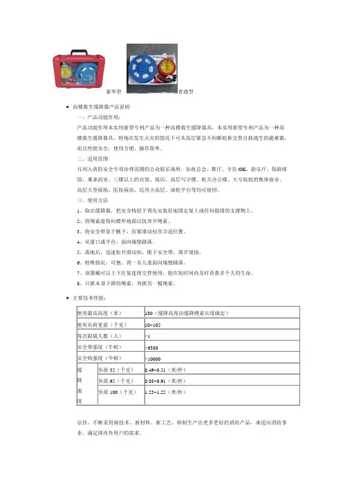
豪华型普通型∙高楼救生缓降器产品说明一、产品功能作用:产品功能作用本实用新型专利产品为一种高楼救生缓降器具,本实用新型专利产品为一种高楼救生缓降器具,特别在发生火灾的情况下可从高层紧急不间断轮换交替自救逃生的避难器,而且性能安全,使用方便,操作简单。
二、适用范围凡列入消防安全专项治理范围的公众娱乐场所,如夜总会、舞厅、卡拉OK、游乐厅、保龄球馆、桑拿浴室、三楼以上的宾馆、饭店、高层写字楼、机关办公楼、大专院校的集体宿舍、高层大型商场、医院病房、民用小高层、油轮平台等均可使用。
三、使用方法1、取出缓降器,把安全钩挂于预先安装好地固定架上或任何稳固的支撑物上。
2、将绳索盘投向楼外地面以抚养开绳索。
3、将安全带套于腋下,拉紧滑动扣至合适位置。
4、从窗口或平台,面向墙壁跳落。
5、落地后,迅速松开滑动扣,脱下安全带,离开现场。
6、特殊情况,可抱、背一名儿童面向墙壁跳落。
7、该器械可以上下往复连续交替使用,能在短时间内及时营救多个人的生命。
8、只抓本身下降的绳索,勿抓另一根绳索。
∙主要技术性能:宗旨,不断采用新技术、新材料、新工艺,研制生产出更多更好的消防产品,来适应消防事业,满足国内外用户的需求。
消防过滤式自救呼吸器一、概述火灾时必然产生有毒烟气,据消防权威部门统计,火灾死亡中,80%以上是因烟气中毒受伤或浓烟窒息后烧死,此时,佩戴可靠的防烟防毒呼吸器,利用疏散通道安全脱离险境,可以大大减少火灾死亡人数。
XHZLC40型和XHZLC60型消防过滤式自救呼吸器就是一种保护人体呼吸器官不受外界有毒气体伤害的专用呼吸器,它利用滤毒罐内的药剂、滤烟元件,将火场空气中的有毒成份过滤掉,使之变为较为清洁的空气,供逃生者呼吸用。
本产品按((中华人民共和国公共安全行业标准》GA209.1999的技术要求制造。
二、用途本呼吸器是宾馆、办公楼、商场、银行、邮电、电力、医院、公共娱乐场所住宅发生火灾事故时,必备的个人防火呼吸保护装置。
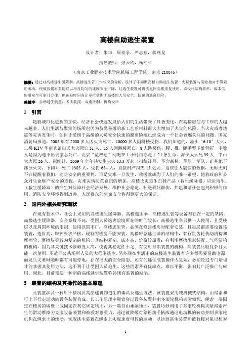
高楼自助逃生装置设计者:朱华,周柏争,严志翔,蒋燕龙指导教师:张云玲,杨红科(南京工业职业技术学院机械工程学院,南京210046)摘要:通过对高楼逃生缓降器、高楼逃生管工作状况的分析,设计了不间断高楼自助逃生装置,夹紧装置与滚轮相对于绳索的滚动,使被救援对象能够以相对均匀的速度安全下降,且逃生装置可再次返回高楼重复使用。
该设计结构简单,成本低,使用安全可靠且方便,能在短时间内让多位受困于高楼的人员安全、快速的逃离危险。
关键字:自助逃生装置;多次救援;双重控制;机构设计1引言随着城市化进程的加快,经济社会快速发展给人们的生活带来了显著变化,在高楼居住与工作的人越来越多,人们生活与聚集的场所也因为易燃易爆的新工艺新材料而大大增加了火灾的风险。
当火灾或者地震等灾害发生时,如何让受困于高楼的人员安全快速的脱离险境已经成为一个社会普遍关注的问题。
国家消防局报道,2005年有2000多人因火灾死亡,10000多人因跳楼受伤。
我们知道的,汕头“6.10”大火,二楼KTV华南宾馆白天大火死亡31人、15人因跳楼死亡,8人跳楼伤,腰、椎、腿手臂多处骨折,多数人是因为逃不出去窒息死亡。
北京“蓝极速”网吧在1小时内夺走了24条生命。
海宁大火死39人;中山大火死26人。
据统计,2009年全年共发生火灾13.3万起(指统计月,不含森林、草原、军队、矿井地下部分火灾,下同),死亡1385人,受伤684人,直接财产损失15亿元。
这些让人震惊的数据,无时无刻不在提醒着我们,消防安全的重要性。
可是灾难一旦发生,救援就成为了人们的唯一希望。
随着政府和公众对生命财产安全的重视,灾难灾情防范意识的增加,高楼火灾逃生自救产品(救生缓降器)应运而生。
(救生缓降器)的产生对保障社会经济发展、维护社会稳定、杜绝群死群伤,共建和谐社会起到积极的作用。
消防安全环境得到改善,人民群众的生命安全将得到更大的保证。
2国内外相关研究现状在现有技术中,社会上采用的高楼逃生缓降器、高楼逃生伞、高楼逃生管等设备都存在一定的缺陷。
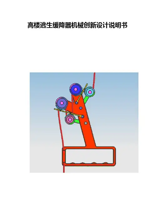
高楼逃生缓降器机械创新设计说明书摘要随着城镇居民的日益增多,高层建筑随处可见,当意外事故发生时,如何安全有效地从高楼逃生成为当前的一大社会难题。
目前的逃生器种类较多,但是大多结构复杂、价格昂贵、不方便使用。
本设计中采用常见的滑轮、连杆机构,设计了一款具有结构简单,使用方便,重量轻等特点的高楼逃生缓降器。
设计书中对逃生缓降器的结构方案、各部件尺寸进行了详细设计,在保证逃生器美观小巧的基础上,利用工程力学的相关知识进行了摩擦阻力计算以及强度校核,以保证设计方案的可靠性和安全性。
设计及验算结果表明,本设计中的高楼逃生缓降器小巧实用,具有广泛的应用前景。
关键词:高楼逃生缓降器创新设计摘要绪论第一章 (4)1.1 (5)第二章 (6)2.1 (6)2.2 (6)2.3 (7)2.4 (8)总结 (11)致谢 (12)附录 (13)参考文献 (17)随着社会的发展,城镇的人口越来越多,很多人居住在高层建筑里。
虽然高层建筑给我们生活带来了方便,但是在发生意外险情如火灾、地震、煤气泄漏等时,高楼逃生成了我们面对的一大难题。
根据调查,我国意外伤亡事故大部分都是由于高楼的防护措施不完善造成的。
目前,当意外险情发生的时候,人们大部分都是通过电梯或楼梯从高楼逃生,但是高楼中的楼梯和电梯都是有限的,而高楼里的居民相对较多,通过有限的电梯和楼梯逃生不可避免会出现拥挤的情况,甚至出现踩踏事件,这样就会造成不必要的人员伤亡。
鉴于此,我们经过认真讨论,设计了高楼缓降逃生器,旨在发生紧急情况时,给人们提供更多的逃生手段,使高楼逃生简便快捷,同时减少意外事故的发生。
众所周知,物体从高处下落,到达地面时速度会很大,因而设计高楼逃生器的关键在于如何保证逃生者以较小的速度到达地面。
目前市面上也有几种高楼救生器,大致可分为阻尼式和减速盘式,其结构分别由钢丝绳、金属外壳、绳轮、转轴、阻尼电机等和环形刹车片、胀力减速盘架、胀力减速拉杆、绳索引导滑轮、拉杆轴等组成,这些装置结构复杂,有的还需要配电机,导致重量过大,操作控制困难,且价格昂贵,不利于普及。
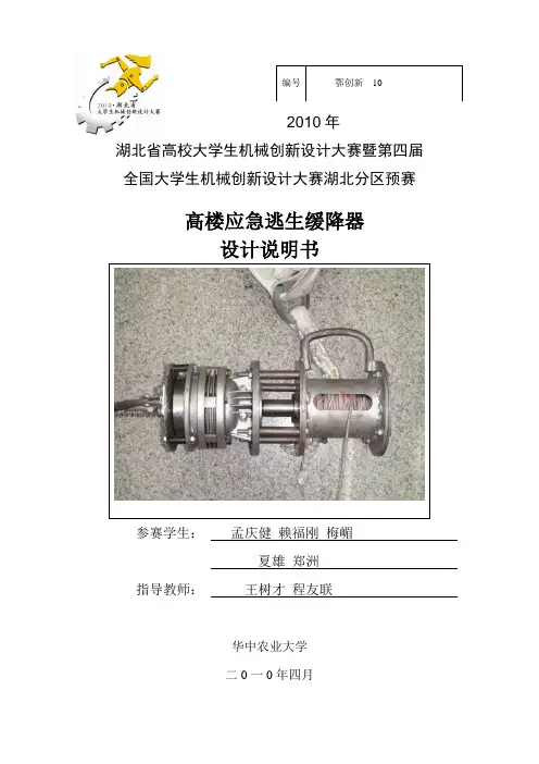
编号鄂创新---10---2010年湖北省高校大学生机械创新设计大赛暨第四届全国大学生机械创新设计大赛湖北分区预赛高楼应急逃生缓降器设计说明书参赛学生:孟庆健赖福刚梅嵋夏雄郑洲指导教师:王树才程友联华中农业大学二0一0年四月2010年湖北省高校大学生机械创新设计大赛暨第四届全国大学生机械创新设计大赛湖北分区预赛作品报名表目录一、研究背景 (3)二、设计目的 (4)三、工作原理 (4)四、机构设计 (5)五、基本参数确定 (6)六、设计计算 (6)1、离合器弹簧的设计与增速器传动比的确定 (6)2、钢丝绳的设计与校核 (8)3、绕线轴的设计与校核 (8)4、离合器轴的设计与校核 (9)5、增速器的设计与校核 (9)6、轴承的设计与校核 (11)7、螺栓的设计与校核 (12)8、联轴器处花键的强度校核 (12)七、创新点及优势 (13)参考文献 (14)附图(部分零件图) (14)高楼应急逃生缓降装置的设计与试验一:研究背景随着城市化进程的加快,高层建筑迅速增多,然而,当发生火灾、地震、恐怖袭击、煤气泄漏等突发事件时,正常的疏散通道不能使用,导致人员不能及时逃离高层建筑,易出现群死群伤的重大事故,因此我们必须设计一种用于高楼应急逃生的装置。
市场上已经存在多种用于高楼逃生的缓降装置,其主要原理包括以下几种:空降器:主要应用能量守恒及空气动力学原理,将救生者的下落时减小的势能转化为空降器旋转的动能,进而带动旋翼旋转,旋转的旋翼将提供一定的升力,以此来减缓救生者下降速率。
该缓降器的主要优点是能够大批量运载遇险人员,但成本较高,不利于推广。
(图1)图1空降器图2 索降救生器夹式高楼逃生装置:该装置主要通过杠杆、连杆双增力机构耒产生制控力来控制匚形槽中的动、定摩擦块夹住绳索并让其匀速下滑。
其主要优点是能够自动控制下降速度,但使用者不能自行控制速度大小,容易引起恐慌,且着地时速度不能及时减为零。
(图3)索降救生器:其原理为绳索纵穿一种缓速下降装置,并用护壳加以固定,利用摩擦原理起到落体减速作用。
《机械创新设计》论文《建筑救生缓降器》设计说明书前言一、创新背景 (3)二、装置作用简介 (3)三、缓降器原理方案 (3)四、缓降器的结构方案及尺寸规格 (4)(1)主要结构及结构参数 (4)(2)数据计算 (6)(3)缓降器适用标准 (7)五、缓降逃生特点 (7)六、结论 (8)一、创新背景:无意中看到一部电影,一个大楼失火,楼上上百人无处可逃,结果有的跳楼了,有的活活烧死了,很惨!如果他们又救生缓降器也许就可以跳楼逃生了,缓降器她和降落伞有些区别,但是很好用,缓降器解决了安全逃生的问题,好安置的特点,可以大范围使用;这样当火灾发生的时候我们就可以保证被困人员能够快速、有效地疏散、安全逃生。
二、装置作用简介:设计的缓降器主要作用是可以帮助人们迅速、平稳、安全的从高处降落至地面而逃生。
该装置主要由新型限速器、绳索卷盘、安全带、安全钩、挂环及连接钢丝绳等组成。
其性能优异,安全可靠。
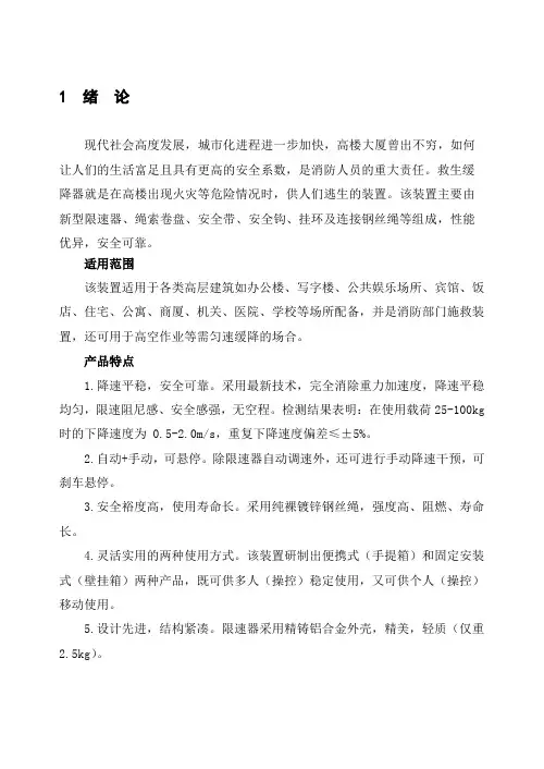
三、缓降器原理方案如图,为缓降器结构原理图救生缓降器为高楼逃生设备,其中摩擦阻尼型的市场份额较大,该缓降器由齿轮逃生器和安全绳索组成。
如图1所示,缓降器采用行星齿轮传动,即固定内齿圈,钢丝绳通过三个导向轮跨绕在绳轮的轮槽内,并将绳轮与行星架制成一体,内齿圈与外壳制成一体,摩擦面设在内齿圈上,两个摩擦块沿着太阳轮周向分布装在太阳轮上,使其同太阳轮一起旋转,并能在太阳轮上沿径向移动沿径向甩出,与制动盘发生旋转摩擦形成制动力,从而自动调节下降速度,实现匀速下降,保证人落地时无冲击感且工作过程无空程。
该缓降器使用了纯裸钢丝绳。
四、缓降器的结构方案及尺寸规格(1)主要结构及结构参数:外壳铸铁(HT350)厚度5~10/cm 最小抗拉强度(MPa)340摩擦滑块 45号钢耐磨耐高温齿轮传动比 1:2.5摩擦材料 45号钢-尼龙9(加30%玻璃纤维填充物)绳索钢丝(钢芯公称直径5mm 公称抗拉强度1670MPa 最小破断拉力14.9kN)安全带1、5—拉钩;2—调速器;3—绳索;4—套环。
International Conference on Modeling, Simulation and Big Data Analysis (MSBDA 2019)Design of a Simple High-Altitude Rescue Buffer DeviceShan Chen*, Junchun Ma and Baoming QiangXi’an Research Institute of High Technology, Xi’an, Shanxi, China, 710025*Corresponding authorKeywords: Buffer device, High-altitude, Rescue.Abstract. With the increasing number of high-rise buildings in cities, people have more and more chances to encounter dangers in high-rise buildings. How to escape safely and quickly has become a hot research issue. Based on this, this paper designs a hydraulic damped high-altitude rescue buffer device based on the principle of hydraulic transmission. On the premise of fully understanding the current market situation of the retarder, the design scheme of hydraulic damper type is put forward at first. Then, according to the five components of the hydraulic system, the overlap of the overall structure of the system is completed. Finally, the model is developed by SolidWorks, a three-dimensional aided design software, and the engineering drawings of the whole system components are designed.IntroductionWith the continuous development of science and technology in China and the continuous improvement of manufacturing industry capacity, the safety of high-rise buildings has been paid more and more attention. From the slower market, there are mainly the following types: Drum type retarder, screw type retarder, friction damper type retarder and hydraulic damper type retarder. From the current market, there are various kinds of retarders. At the same time, people are looking forward to the emergence of retarders which are easy to operate and can control the speed of descent by themselves. That is to say, the new type of retarder should embody more humanistic design ideas, take into account the factors of different weights, so that the trapped personnel can use it without complicated training, that is, it needs to have simple structure, easy installation, short setup time, fast evacuation personnel and so on.Overall Scheme DesignThe design of hydraulic damper retarder is mainly aimed at the situation that people are trapped and unable to use elevators, stairs or lifesaving passages normally when fire or danger occurs in high-rise buildings. Therefore, on the premise of safety, the design should make the structure of the device as simple as possible, the volume as small as possible, and the users can flee the dangerous zone quickly. The hydraulic damped retarder is composed of a hydraulic cylinder and a throttle valve. Its working principle is shown in Fig. 1 below.Figure 1. Schematic diagram of hydraulic damper retarderThe specific working process is as follows: The trapped people wearing safety life jackets fell because of their self-esteem. The wire rope connected to the human body then drives the drum to rotate, and the drum drives the crank-connecting rod mechanism at both ends to rotate. The function of crank-connecting rod mechanism is to convert the circular motion of the drum into the linear reciprocating motion of the double-acting hydraulic cylinder with double piston rods, and complete the conversion of motion. Because the crank connecting rod mechanism is connected with the hydraulic cylinder rod, the hydraulic cylinder, under the action of the crank, presses the hydraulic oil from one oil chamber to another. In order to control the descending speed of personnel, the flow of oil must be controlled by throttling device. By controlling the throttle orifice size of throttle valve, controlling the oil flow speed, and then through the internal feedback of the system, controlling the rotational speed of the drum, the purpose of controlling the descending speed of the personnel is achieved.Structural Design and Component SelectionHydraulic transmission system is generally composed of five parts: energy device, actuator, control throttle device, auxiliary device and transmission medium. In the specific design process, according to these five parts, the components of each part are selected, calculated and finalized in turn, and then the overall structure and function of the device are finalized.Selection of Energy DevicesIn the hydraulic transmission system, engineers usually use hydraulic pump as the energy device. Its advantages are obvious, such as smooth transmission, large load, step less speed regulation, etc. Its disadvantages also follow, such as complex structure, too large volume, heavy weight, lack of flexibility, inconvenient device movement, etc. Therefore, this paper adopts passive hydraulic system, does not use any mechanism driven by external power of energy as the energy device, and directly connects the two oil chambers of hydraulic cylinder through oil pipes, thus avoiding the heavy design problem of the device in principle.Selection of the ActuatorIn the hydraulic transmission device, the main actuators are hydraulic cylinder and hydraulic motor, whose main function is to convert hydraulic energy into mechanical energy. For the hydraulic damped retarder in this paper, its actuator is hoisting mechanism and hydraulic cylinder. First, the selection of hoisting mechanism. When high-level rescue of personnel or materials is carried out, the movement of rescued personnel and materials is in the vertical direction. Therefore, the hoisting mechanism is selected as the intermediate device, and the movement of the personnel in the vertical direction is converted into the circular motion of the drum through the drum, which drives the rotation of the drum and greatly extends the height of rescue. Secondly, the selection of hydraulic cylinder, because the hoist mechanism converts the movement of personnel into circular movement, at the same time considering that the passive system is composed of hydraulic cylinder and various auxiliary mechanisms. Therefore, as long as the circular motion of the drum is converted into the linear motion of the hydraulic rod, which drives the hydraulic rod to move in the linear direction, the mechanical motion conversion between the actuators can be realized, thus connecting the extension and retraction speeds of the hydraulic rod with the rising and falling speeds of personnel. Selection of Control Throttle DeviceIn a hydraulic transmission system, no matter how complex its functions and the number of components are, its oil circuit is composed of hydraulic components that control the direction, pressure and flow of oil in the hydraulic system. From the point of view of hydraulic damper, the function of the control device is to control the descending speed of the personnel. Belt brake and throttle valve are the ways to control speed. Finally, the control element--throttle valve is adopted in this paper. The following aspects are mainly considered: First of all, the belt brake is adopted, and thekey point of the whole system falls on the friction torque between the belt and the drum. To control the uniform speed, deceleration or stop of the personnel in the descending process, it is necessary to control the torque applicator, which will add additional control mechanisms and complicate the system structure. Moreover, the emergency rescue situation is full of uncertain factors, which will affect the application of friction torque in rainy days or humid environments, causing extremely easy slippage and limiting the time and scope of use. Secondly, from the cost point of view, the cost price of a single throttle valve is 30 to 40 RMB. Compared with the cost price of belt brake thousands RMB, its manufacturing cost is low, which is convenient for large-scale promotion.Selection of Auxiliary DevicesBracket: It is the basic frame and main bearing mechanism of the whole device. In order to ensure that the system can work steadily throughout the normal working process, the triangular structure is adopted in the design of the bracket. Crankshaft: It is a force transmission mechanism, which connects the hydraulic cylinder and the drum, and converts the circular motion of the drum into the linear motion of the hydraulic cylinder. Tee: It is the interface of the whole passive hydraulic system to replenish the oil. When it is necessary to replenish the oil to the system, the third interface is used to replenish the oil to the oil chambers on both sides of the hydraulic cylinder. When working normally, the third oil outlet is plugged with a plug to form a closed space and form a passive hydraulic transmission system.Selection of Transmission MediumCommonly used hydraulic oils are classified according to working pressure and viscosity: L-HL hydraulic oil, L-HM anti-wear hydraulic oil, L-HV low temperature anti-wear hydraulic oil, L-HS Low setting anti-wear hydraulic oil, L-HG hydraulic guide oil, fire-resistant hydraulic oil. Viscosity grades of hydraulic oils are divided into 22, 32, 46, 68, 100, etc. at 40 C, but their properties have their own characteristics. Because the hydraulic cylinder is used as the actuator, according to the relevant regulations of the state, the oil in the whole hydraulic circuit must be made of 46 at the same time, L-HL oil is selected because the working pressure of the system is less than 7MPa.Usage MethodFix the Descent control device on the balcony, ceiling, corridor and other places. When there is a fire, the evacuees should fasten their safety belts and then fasten the safety belts to the rope buckles of Descent control device. By adjusting the throttle opening to different positions, the oil flow through the throttle valve is different in unit time. According to the requirements, this Descent control device has designed three different downshifts and one emergency stop gear. The first gear is set within 50 Kg, the second gear is set within 50 kg to 70 Kg, the third gear is set above 70 kg, and the fourth gear is set for emergency stop.Modeling and SimulationIn this paper, the process of modeling needs to be continuously improved. First, the development of the model. SolidWorks is used to model the hydraulic damping Descent control device. As the actual size of Descent control device is completely uncertain before the product is completely finalized, the previous model development mainly verifies the feasibility of the scheme in terms of scheme, principle and structure. Secondly, the determination of component model. On the basis of the feasibility of the scheme, relevant calculations are carried out. According to specific national standards, the parameters of hydraulic components are integrated into standard parts as far as possible to reduce the cost of the whole system. Finally, the parameters are improved. The component size and installation size of the model initially developed in the early stage are improved, and the calculated parameters are kept consistent with the three-dimensional model as far as possible. Due to the limitation of space, the modeling process of hydraulic cylinder is introduced as an example.Previously, through market research, the model of hydraulic cylinder has been determined MOD30 *200-50, and the parameters of hydraulic cylinder have been checked and calculated. The components of each module have been clearly understood. According to the analysis idea, firstly, using the top-down analysis idea, according to the mastered principle, structure and composition, the hydraulic cylinder is divided into: rear end cover, cylinder barrel, piston, piston rod, front end cover, fastening connecting rod and sealing device.PistonThe diameter of the piston is 30mm and the diameter of the piston rod is 16mm, therefore, the piston and the piston rod are connected by threads. The entire piston thickness is 10 mm. The normal operation of the hydraulic cylinder depends on the sealing effect between the piston and the cylinder barrel to isolate the oil inlet chamber and the oil outlet chamber from each other. According to the needs, the sealing ring for the hole is selected, and OSI type piston special seal or UPI type piston and piston rod can be used.Piston RodThe two-way hydraulic cylinder is selected in the form of cylinder body fixation. The one-way stroke of the piston rod is 200mm, the total length of the piston rod is 400mm, and the total stroke of the hydraulic cylinder is 600 mm. In order to avoid oil leakage at the end of the hydraulic cylinder when the piston rod works, a sealing ring should be used for the shaft between the piston rod and the end cover. The sealing ring should be used for IDI type piston rod or UPI type piston and piston rod to strengthen the sealing performance of the device. When installing, pay attention to whether the hydraulic cylinder will touch the ground. As the hydraulic cylinder works unilaterally, an adjustable section of 50mm is left at one end, which is convenient for installation and debugging of the hydraulic cylinder. The model is shown in fig. 2.Front and Rear End CapsFront and rear end caps are fixed mechanisms of the whole device, which fix cylinder, piston rod and other parts together as a whole. At the same time, for the double-acting rod, front and rear end caps also play a guiding role, providing the basic direction of motion for the piston rod. The model is as follows Fig. 3 Show.Figure 2. Piston rod model Figure 3. Model of end cap(1) Drawing command, select up-looking datum plane, make piston diameter 30 mm, set end cap length 40 mm, width 40 mm, height 20 mm Rectangular block;(2) For stretching command, the front guide orifice is a cylindrical guide orifice with an outer diameter of 22 mm and a height of 6 mm.(3) For the first stretching excision, a cylinder with a diameter of 32 mm and a depth of 15 mm was excised by stretching.(4) The second stretching excision, in front of the base plane, stretching excision diameter of 18 mm through-hole cylinder;(5) Circumferential array, making four through holes with diameter of 8 mm, center distance of 30 mm, fastening the installation position of connecting rod;(6) Choose G1/4 threaded hole through hole, 8 mm from the base of end cap, which is the import and export of oil.The piston diameter of the hydraulic cylinder is 30mm. The cylinder with inner diameter 30mm, outer diameter 32mm and wall thickness 2mm is selected. The oil inlet and outlet at both ends are set as G1/4 threaded holes, and the center distance between the two holes is 186mm. The model is as follows Fig.4 shows.Fastening Connecting RodThe fastening connecting rod is a double-head bolt, which is easy to draw. You can either draw it by yourself or look for it in the standard parts library on Midi's secondary development platform. The design of double-headed bolt has been parameterized. You can choose the corresponding parameters. Here you can choose the thread M8. Model As shown in Fig.5.Improvement of the ModelThe hydraulic cylinder shall be installed from inside to outside and from left to right, and parts shall be assembled as far as possible according to its working position and structural distribution. It is mainly to add the constraint relation between each component, and the added constraint shall conform to the actual working conditions. After the installation is completed, the model shall be functionally checked. Firstly, the model is checked for coherence to detect whether there are too many constraints and unreasonable constraints in the assembly process and whether the assembled parts coincide with each other. Secondly, the motion simulation of the model is aimed at the physical simulation of the hydraulic components in the working process to observe whether each component can work normally under the given conditions. The model is shown in Fig.6 below.Figure 4. Cylinder model Figure 5. Fastener model Figure 6. Hydraulic cylinder model The above is the process of using SolidWorks software to model the hydraulic cylinder as an example. The other component models are similar to this process, and finally the device is obtained. The model is shown in Fig.7.Figure 7. Hydraulic damper modelBuffer and rescue devices in high-rise buildings are a direction of the development of safety products in public places, and they have a large market in today's high-rise buildings. In this paper, the design of the device is mainly based on the principle of hydraulic damper, and the main work is as follows: (1) Conception of the scheme. By collecting the products of the retarder on the market at present, the design scheme of hydraulic damper is put forward. (2) Overlapping of the overall structure of the system. According to the five components of the hydraulic system, the components of the system are determined one by one. (3) Selection of components. According to the requirement, the parameters of device components are selected. (4) Model development. The model is developed by SolidWorks, a three-dimensional aided design software, and the related dimensions are perfected. The engineering drawings of the whole system components are designed.Reference[1] Han Yuyong, Liu Yunhui and Li Ziguo. Design of Life Saving Descent control device Based on Dynamic Theory Analysis and Simulation[J]. Fire Science and Technology, 2015, (10): 1380-1386.[2] Wu Shuqin, Suo Shuangfu, Huang Tao, Zheng Wenjiao, Liu Xiangfeng and Wang Yuming. Research on Energy Dissipation of Self-cooling Friction Descent control device [J]. Mechanical Design, 2013, (03): 86-88+92.[3] Wang Wenkai, Song Haichao. Design of a Speed Regulation Braking System for a Multifunctional Escape Descent control device [J]. Hydraulic and Pneumatic, 2012, (11): 35-37.[4] Wei Jianjun. Research and Development of Centrifugal Friction High-rise Escape Descent control device [J]. Manufacturing Automation, 2012, (04): 90-92.[5] Lan Zimian, Zhong Qing. A Design of Escape Hydraulic Descent control device [J]. Hydraulic and Pneumatic, 2011, (12): 7-8.。
1 绪论现代社会高度发展,城市化进程进一步加快,高楼大厦曾出不穷,如何让人们的生活富足且具有更高的安全系数,是消防人员的重大责任。
救生缓降器就是在高楼出现火灾等危险情况时,供人们逃生的装置。
该装置主要由新型限速器、绳索卷盘、安全带、安全钩、挂环及连接钢丝绳等组成,性能优异,安全可靠。
适用范围该装置适用于各类高层建筑如办公楼、写字楼、公共娱乐场所、宾馆、饭店、住宅、公寓、商厦、机关、医院、学校等场所配备,并是消防部门施救装置,还可用于高空作业等需匀速缓降的场合。
产品特点1.降速平稳,安全可靠。
采用最新技术,完全消除重力加速度,降速平稳均匀,限速阻尼感、安全感强,无空程。
检测结果表明:在使用载荷25-100kg 时的下降速度为 0.5-2.0m/s,重复下降速度偏差≤±5%。
2.自动+手动,可悬停。
除限速器自动调速外,还可进行手动降速干预,可刹车悬停。
3.安全裕度高,使用寿命长。
采用纯裸镀锌钢丝绳,强度高、阻燃、寿命长。
4.灵活实用的两种使用方式。
该装置研制出便携式(手提箱)和固定安装式(壁挂箱)两种产品,既可供多人(操控)稳定使用,又可供个人(操控)移动使用。
5.设计先进,结构紧凑。
限速器采用精铸铝合金外壳,精美,轻质(仅重2.5kg)。
2 总体方案设计22 总体方案设计设计题目:缓降器性能试验机设计 设计要求:1)了解缓降器性能试验机的用途,主要构成;策划系统的总体结构和实现方案。
2)了解缓降器性能试验机的工作原理,设计缓降器性能试验机的机械结构。
3)完成缓降器性能试验机的电气部分设计。
包括:直流电机的加载原理,直流电机控制器的控制电路,拉力测量电路设计,线速度测量电路设计,微机计数卡的原理框图,控制软件流程图。
4)完成翻译译文,最少工作量为5000汉字。
5)针对本课题内容需要绘制4张0A 工作图,撰写2万字设计说明书。
设计参数:1、绳的直径:4mm 。
2、下降速度:1.5~2.0m/s 。
缓降器机械设计课程设计一、课程目标知识目标:1. 学生能理解缓降器的基本原理,掌握其机械结构设计的关键技术。
2. 学生能够运用物理知识,分析并计算缓降器的力学性能,如力矩、速度和稳定性等。
3. 学生了解并掌握材料力学在缓降器设计中的应用,能够合理选择材料和评估其耐用性。
技能目标:1. 学生能够独立完成缓降器机械设计的全过程,包括需求分析、方案设计、详细设计和计算校核。
2. 学生通过使用CAD软件,能够绘制出精确的缓降器部件图和装配图。
3. 学生能够运用工程手册和资料,进行必要的工程估算和数据分析。
情感态度价值观目标:1. 学生通过团队协作完成设计项目,培养合作精神和解决问题的能力。
2. 学生在设计过程中,能够体会到科技对生活的积极影响,增强创新意识和责任感。
3. 学生在项目实施中,学会尊重工程实践,形成严谨的科学态度和良好的工程素养。
课程性质分析:本课程为高年级工程技术类课程,旨在通过实际机械设计项目的开展,提升学生的理论应用能力和实践创新能力。
学生特点分析:高年级学生已具备一定的物理和工程基础知识,具有较强的逻辑思维能力和动手操作能力,能够承担较为复杂的工程设计任务。
教学要求:结合学生特点,课程要求学生在掌握理论知识的基础上,注重实践操作和团队协作,将所学知识应用于实际问题的解决中,确保学习成果的实用性和可操作性。
通过本课程的学习,学生应能够达到上述具体的学习成果。
二、教学内容1. 理论知识:- 缓降器原理及其在工程中的应用。
- 机械设计基础,包括机械制图、材料力学、力学性能计算等。
- 稳定性和可靠性分析的基本方法。
2. 实践技能:- 缓降器设计流程和方法,包括需求分析、方案设计、详细设计和计算校核。
- 使用CAD软件进行图纸绘制。
- 利用工程手册和资料进行材料选择、力学分析和工程估算。
3. 教学大纲:- 第一周:缓降器原理介绍,学习目标设定,分组讨论确定设计主题。
- 第二周:机械设计基础知识回顾,进行需求分析和方案设计。
说明书
一、设计名称:实用救生缓降机
二、设计背景:现代社会,随着建筑技术的不断发展,我们身边树起了一座又一座高楼,楼房的建设从一定程度上节省了土地资源,但是却随之而生一系列安全问题。
全国范围内楼房频发火灾,在这种情况下,人能够安全逃生显得尤为重要,但是楼房的高度给逃生带来困难。
针对这一情况,设计出一简单实用高楼逃生装置。
三、设计方案:
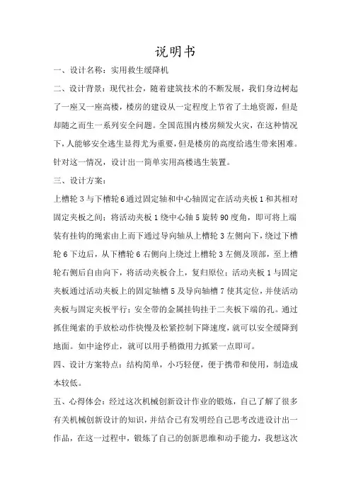
上槽轮3与下槽轮6通过固定轴和中心轴固定在活动夹板1和其相对固定夹板之间;将活动夹板1绕中心轴5旋转90度角,即可将上端装有挂钩的绳索由上而下通过导向轴从上槽轮3左侧向下,绕过下槽轮6下边后,从下槽轮6右侧向上绕过上槽轮3左侧及顶部,至上槽轮右侧后自由向下,将活动夹板合上,复归原位;活动夹板1与固定夹板通过活动夹板上的固定轴槽5及导向轴槽7使其定位,并使活动夹板与固定夹板平行;安全带的金属挂钩挂于二夹板下端的孔。
通过抓住绳索的手放松动作快慢及松紧控制下降速度,就可以安全缓降到地面。
如中途停止,就可以用手稍微用力抓紧一点即可。
四、设计方案特点:结构简单,小巧轻便,便于携带和使用,制造成本较低。
五、心得体会:经过这次机械创新设计作业的锻炼,自己了解了很多有关机械创新设计的知识,并结合已有发明经自己思考改进设计出一作品,在这一过程中,锻炼了自己的创新思维和动手能力,我想这次
锻炼将会对自己之后的学习生活产生积极地影响。