XCE限位开关选型指南2006
- 格式:pdf
- 大小:793.46 KB
- 文档页数:2


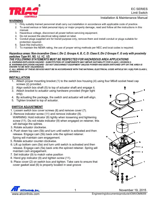
ELECTRICAL WIRING1. Remove switch box cover (7) and indicator (9). (See switch adjustment sections 1 and 2).2. Remove protection plugs from conduit entries and install conduit or plugs suitable for type of protection required.3. Engage wires in terminal strip (10) using a small screwdriver (1/8” blade).FOR WIRING DIAGRAM, REFER TO THE LABEL INSIDE OF THE HOUSING.A MAX OF THREE SWITCHES IS PROVIDED. ONLY A MAX OF TWO OUTPUTS CAN WORK SIMULTANEOUSLY; EACH OF THE OUTPUTS CAN BE CHARGED WITH FOLLOWING RATING, WHERE THE SUM SHOULD NOT EXCEED A MAXIMUM TOTAL OUTPUT 5 A:FOR ELECTRICAL RATINGS OF THE SWITCHES, REFER TO THE LABEL ON THE OUTSIDE OF THE HOUSING .A-T Controls product, when properly selected, is designed to perform its intended function safely during its useful life. However, the purchaser or user of A-T Controls products should be aware that A-T Controls products might be used in numerous applications under a wide variety of industrial service conditions. Although A-T Controls can provide general guidelines, it cannot provide specific data and warnings for all possible applications. The purchaser / user must therefore assume the ultimate responsibility for the proper sizing and selection, installation, operation, and maintenance of A-T Controls products. The user should read and understand the installation operation maintenance (IOM) instructions included with the product, and train its employees and contractors in the safe use of A-T Controls products in connection with the specific application.While the information and specifications contained in this literature are believed to be accurate, they are supplied for informative purposes only. Because A-T Controls is continually improving and upgrading its product design, the specifications, dimensions and information contained in this literature are subject to change without notice. Should any question arise concerning these specifications, the purchaser/user should contact A-T Controls.For product specifications go to /A-T Controls, Inc. • 9955 International Boulevard, Cincinnati, OH 45246 • Phone: (513) 530-5175 • Fax: (513) 247-5462 • Wiring Schematic for Type 0A, 0C, & 1D, N1, N3 Wiring Schematic for Types 1J & 1A, 1C。
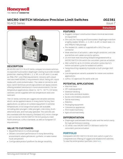
MICRO SWITCH Miniature Precision Limit Switches914CE SeriesDESCRIPTIONAll MICRO SWITCH 914CE Series compact enclosed switches incorporate fluorocarbon diaphragm sealing to provide reliable protection, meeting NEMA 1, 2, 3, 3R, 4, 6, 6P, and 13, as well as IP66, IP67, and IP68 requirements. Versions with a boot seal also meet NEMA 12 requirements (dust, falling dirt, liquid media with solid contaminates). The cable or connector and basic switch terminals are encapsulated in an epoxy sealant, offering excellent resistance in harsh environments. For low temperature applications (down to -40 °C, -40 °F), CE Series switches can be supplied with low temperature seals and lubricant.The CE Series switches are rugged and versatile switches which can be applied indoors in many harsh factory floor applications, as well as on outdoor equipment in extreme temperatures. A full range of actuators are available,including plain plungers, roller plungers, side rotary, multi-directional wire, and manually operated. The switches are also available with the industry standard, M12 micro-change 4-pin connector. MICRO SWITCH 914CE products meet North American, cURus standards, as well as European CE requirements.VALUE TO CUSTOMERS• Big performance in a small package• Delivers consistent performance in many demanding environments where petroleum, synthetic, or water based fluids are present• Configurable product platform for design versatilityFEATURES• Rugged, compact construction means minimal real estate on equipment• Die-cast zinc housing and fluorocarbon diaphragm maintain a tightly sealed, NEMA 1, 2, 3, 3R, 4, 6, 6P, 12 (boot seal), 13, and IP66/67/68 package• Pre-leaded (UL cable) or supplied with a M12 four-pin connector• Wide selection of actuators, cable length variations, and side and bottom exit cable/connector options• 25 mm hole-hole mounting footprint engineered with a MICRO SWITCH SM switch for consistent, precise actuation • Well suited for up to 10 million actuation cycles (Up to 5 million actuation cycles for wobble actuators)• Gang mounting capability to provide a multi-plunger limit switch• Low temperature variants available for indoor and outdoor applications• cURus, CE approvals for world-wide usePOTENTIAL APPLICATIONS• Machine tools• Off-road equipment • Material handling• Dock locks and dock levelers • Access and mobility solutions • Textile machinery • Robotics• Packaging equipment • Commercial appliances • Print trade machinery • Agricultural machineryDIFFERENTIATION• Diaphragm seal between the actuator and the switch cavity for high performance sealing• CE series uses MICRO SWITCH SM basic switch for consistent, precise actuationPORTFOLIOHoneywell’s MICRO SWITCH 914CE limit switch is part of a comprehensive offering of rugged and reliable limit switches. To view the entire product portfolio, click here .Sensing and Internet of Things002381Issue 7Table 1. SpecificationsTable 2. Electrical Ratings (in amperes)Model example Contacts Rating914CE* - * Silver contacts A914CE* - *G Gold contacts B914CE* -Q, -AQ, -AQ1, -Q2Silver contactsC with 4 pin connector2 SWITCHING AND LEAD IDENTIFICATION914CErow.BOTTOM EXIT OR SIDE EXIT ORIENTATIONThe CE Series has been designed with a pre-wired cable fittedin the bottom of the switch housing. Other variations are availa-ble with a side exit cable.GOLD CONTACT VERSIONSFor low energy applications (up to 30 Vdc, 1 A), gold contactversions of the 914CE switches can be supplied upon request.Sensing and Internet of Things 34 44 mm max.[1.73 in max.]25 mm [0.98 in]16 mm max.[0.63 in max.]40 mm max.[1.57 in max.]Max. free lengthOperating position (OP) 3 mm min. [0.12 in min.]8,0 mm [0.31 in]8,0 mm [0.32 in]7,6 mm [0.30 in]Pretravel (PT)Overtravel (OT)CABLE VERSIONTYPE Q OE Q2TYPE Q1M12thread1/2 x 20 UNF threadTwo (2) holes Ø 5.1 mm [Ø 0.2 in] dia. c/bore10,2 mm dia x 6 mm deep [0.40 in dia x 0.24 in deep](Both sides - option “A” only)GENERAL DIMENSIONS • ALL SWITCHESPRODUCT NOMENCLATURE914CESwitch Type29Actuator TypeOptions 1914CE Series Small Precision Limit Switch–3Cable LengthConnectorsBottom exit is standard.NOTE: not all combinations of model code are available.Please contact your Honeywell provider/representative for assistance.1More than one option may be permissible.PRODUCT SPECIFICATIONS AND LISTINGSContact your Honeywell rep or distributor for additional listingsSensing and Internet of Things 56 Note: part numbers are shown with 3 ft of cable. The -X indicates the number of feet of cable provided. 6-foot, 9-foot, and 12-foot lengths along with custom lengths, are also available.Sensing and Internet of Things 7Note: part numbers are shown with 3 ft of cable. The -X indicates the number of feet of cable provided. 6-foot, 9-foot, and 12-foot lengths along with custom lengths, are also available.8 m WARNINGPERSONAL INJURYDO NOT USE these products as safety or emergency stop devices or in any other application where failure of the product could result in personal injury.Failure to comply with these instructions could result in death or serious injury.m WARNINGMISUSE OF DOCUMENTATION• The information presented in this product sheet is for reference only. Do not use this document as a product installation guide.•Complete installation, operation, and maintenanceinformation is provided in the instructions supplied with each product.Failure to comply with these instructions could result in death or serious injury.ADDITIONAL MATERIALS• Product installation instructions • Product range guide • Product nomenclature tree• Product application-specific information– Limit and enclosed switches application information – Limit and enclosed switches operating characteristics – Limit and enclosed switches reference standards – Limit and enclosed switches typical applications – Product flyer: CE Family Miniature Limit SwitchesWarranty/RemedyHoneywell warrants goods of its manufacture as being free of defective materials and faulty workmanship during the appli-cable warranty period. Honeywell’s standard product warranty applies unless agreed to otherwise by Honeywell in writing; please refer to your order acknowledgment or consult your local sales office for specific warranty details. If warrantedgoods are returned to Honeywell during the period of coverage, Honeywell will repair or replace, at its option, without charge those items that Honeywell, in its sole discretion, finds defec-tive. The foregoing is buyer’s sole remedy and is in lieu of all other warranties, expressed or implied, including those of merchantability and fitness for a particular purpose. In no event shall Honeywell be liable for consequential, special, or indirect damages.While Honeywell may provide application assistance personally, through our literature and the Honeywell web site, it is buyer’s sole responsibility to determine the suitability of the product in the application.Specifications may change without notice. The information we supply is believed to be accurate and reliable as of this writing. However, Honeywell assumes no responsibility for its use.Viton ® is a registered trademark of DuPont Performance Elastomers L.L.C.002381-7-EN | 7 | 06/18© 2018 Honeywell International Inc. All rights reserved.For more informationHoneywell Sensing and Internet of Things services its customers through a worldwide network of sales offices and distributors. For application assistance, current specifications, pricing or the nearest Authorized Distributor, visit or call:Asia Pacific +65 6355-2828Europe +44 (0) 1698 481481USA/Canada+1-800-537-6945Honeywell Sensing and Internet of Things 9680 Old Bailes Road Fort Mill, SC 29707 www. 。
XC2006A位置控制仪RigourIII+ Ver4.0使用说明书无锡市迅成控制技术有限公司无锡市桐伟机械自动化有限公司已通过ISO9001:2000质量管理体系认证第一章系统概述§1.1产品简介XC2006位置控制仪是XC2005/XC2004的改进型,采用320×240大屏幕显示。
产品外观、安装尺寸以及端子台的排列与XC2005一致。
采用24点阵字体显示以便于观察机器的运转状态。
参数设置参照XC2005,兼顾易用性与灵活性,力求能覆盖大多数的应用机型同时操作上尽可能简单。
某些参数由系统指派,如果用户有其它要求也可人为设置。
采用独立的数字脉冲模块,提高了频率精度,使送料电机(以下简称:轴电机)的运行更加平稳,速度有所提高。
支持双轴机械(双步进或双伺服),并可采用双色标加浮动辊控制方式。
适用机型丰富,可不断扩充(而非修改)。
目前系统内部已集成了7种基本机型和4个机型选项,可组合成多种机型。
§1.2关于RigourIII+RigourII是XC2005系列位置控制仪系统软件的名称。
RigourII在应用中会不断地被修改与扩充,这是软件的一般规律。
为使这些修改具有可追溯性,必须对每一次修改分别命名,即软件版本号。
命名规则如下:RigourIII+ Ver1.0.0应用性修改*0或空白:标准版其它:特殊应用版,修改代号一般性修改*0:原始版本其它:修改代号升级代号名称*说明:一般性修改:针对软件的某些错误或不合理处的修改。
控制功能不变。
应用性修改:针对某一特殊应用要求所作的修改。
软件的控制功能改变。
版本确认:用户订货时,必须声明软件版本号,否则以标准版供应。
所有的应用性修改一旦被用户确认,该版本号会在操作界面中显示。
§1.3主要技术指标1.供电电源:220V (AC )±10%;50Hz/60Hz ; 2.外形尺寸:238mm(宽)×120mm(高) ×110mm(深); 3.开孔尺寸:242mm(宽)×124mm(高); 4.脉冲频率:200~9500Hz ; 5.显 示:LCD 128×64; 6.驱动支持:双轴;7.软 件:RigourIII + Ver4.0;第二章 操 作§2.1操作面板—霍尔— —色标— 运转 脱料 冲孔 色标 脉冲 GK1 GK2 GK3GK4图1 指示灯显示图2 运行显示§2.1.1 上电/运行显示无论主电机是否运转均称为‘运行状态’,以区别于‘设置状态’。
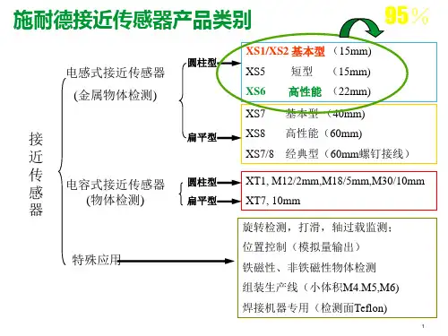
关于位置开关(行程开关和接近开关)选型及应用,一篇文章就够了位置开关在在自动化控制中用于设备的移动位置判断,比较常见的是行程开关(限位开关)和接近开关。
位置开关种类位置开关有接触式的行程开关(限位开关)和非接触式的接近开关两类。
1、行程开关(限位开关)行程开关(限位开关)属于接触式机械开关,是由设备运动部件的碰撞来发出控制命令的主令电器,常用于控制生产机械的运动方向、速度、行程大小或位置。
常见的如用于行车上用来改变运行方向的限位开关。
常见实物如图所示:2、接近开关接近开关属于非接触式无触点行程开关,当某种物体与接近开关接近到一定距离时,接近开关就发出动作信号,它不像机械行程开关那样需要施加机械力,而是通过其探头与被测物体间介质能量的变化来获取信号。
接近开关的应用极其广泛已经超出了限位和保护的范畴,常用的有用来测量速度,对液面位置的控制,检测金属体等等。
行程开关工作原理及优缺点行程开关(限位开关)的工作原理相对于比较简单,其内部有常开和常闭的触点,主要靠生产机械某些运动部件碰撞开关的连杆驱动开关的触点引起动作,使闭合的触点分断或者断开的触点闭合。
由开关触点状态的改变去控制电路和机构的动作。
◆ 行程开关优点①无论何种材质,只要接触的操作力达到一定值,就出发开关。
②采用接点输出方式,可以随外接电压不同而输出不同,无漏电现象。
③不受相邻传感器的影响,输出稳定。
◆ 行程开关缺点:①接触式行程开关会磨损和损伤检测对象物,精密物体不建议采用该方法②接触式行程开关机械寿命有限制。
在前面行程开关的缺点中提到了,行程开关会磨损和损伤被测对象,同时测量精度不高,使用寿命有限制等这些缺点。
而接近开关的出现很好的解决了这些问题,那么接近开关有那些优缺点呢?接近开关优缺点◆ 接近开关的优点①接近开关为非接触测量,不会磨损和损伤检测对象物。
②接近开关采用无触点输出方式,因此寿命延长,采用NPN/PNP输出,对触点的寿命无影响.③接近开关不受检测对象的污渍和油、水等的影响。
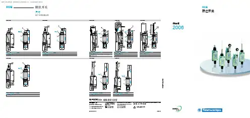
限位开关型号之触点模块:
根据用户的不同需求,可选择慢动触头或速动触头,选择肯定断开功能,选择不同的触点数。
限位开关型号之外壳:根据限位开关的负载不同,对于轻型和重型负载,外壳材料多采用塑料;对于中-重型负载、重型负载及超重型负载,外壳多采用金属。
选择合适的外形尺寸。
限位开关型号之进线模块:
提供符合不同标准的进线方式,除了直接成型电缆接入外,常用的有:ISO、DIN、NPT 等各种标准的电缆密封管形式,其区别仅在于由于制式的不同,引起限位开关进线口螺纹的内径尺寸和螺纹间距的不同。
限位开关型号之操作头:
根据检测目标的外形与运动方向的不同,选择不同的操作头,操作头的类型有直动式、滚轮直动式、滚轮推杆式、滚轮摇杆式、万向式等。
限位开关型号之最小力:触发所需的最小力,通常有最小力(N)和最小力矩(N.m)两种。
限位开关型号之操作速度:所允许的最大触发速度,若超出此速度,限位开关可能会由于受力过大而误动作或损坏。