KUKA机器人介绍KR16
- 格式:doc
- 大小:2.11 MB
- 文档页数:7
KUKA基础培训之机器人系统的结构和功能一. 机器人系统的概念机器人系统是由机器人、控制器、传感器、执行器以及其它相关设备组成的一种自动化装置,用于完成一定的生产任务。
机器人系统具有高度的智能化和灵活性,打破了传统生产线固定式的限制,可以灵活应对各种工作任务和生产需求。
二. KUKA 机器人系统简介KUKA机器人系统是一种高度智能化的自动化装置,由机器人本体、控制器、传感器、执行器、通信模块及其它相关设备组成。
KUKA机器人系统可以分为五大系统,分别是机械系统、传动系统、控制系统、传感器系统和应用软件系统。
2.1 机械系统KUKA机械系统包括机器人的本体和手臂,由铝合金、结构钢等制作而成。
机器人手臂的设计和结构具有绝对的创新性和先进性,具有高度的稳定性、刚性和精度。
2.2 传动系统KUKA传动系统通过电机、减速器、齿轮以及传动链条等组成。
KUKA机器人的传动系统具有精确的定位和运动控制功能,可以实现高度精密的运动控制和动作规划。
2.3 控制系统KUKA控制系统是一种高度智能化的控制系统,可以实现机器人运动的控制和规划。
控制系统包括控制器、通信模块和集成的软件,通过软硬件的集成,尽可能地优化了机器人的性能。
2.4 传感器系统KUKA机器人的传感器系统包括大量的传感器和感应器,用于实现机器人的感知和控制。
主要包括力传感器、视觉传感器、接触传感器等。
2.5 应用软件系统KUKA机器人的应用软件系统可以实现机器人系统的高度自动化和集成化,包括编程软件、仿真软件和其它各种软件组件,可以实现机器人的运动控制和规划等各种功能。
三. KUKA机器人系统的功能KUKA机器人系统具有高度的智能化和灵活性,具有以下主要功能:3.1 自动化生产功能KUKA机器人系统可以实现自动化生产,可以在不停机的情况下完成工件的生产和制造,显著提高了生产效率和产品质量。
3.2 精密加工功能KUKA机器人系统具有高度的精密加工能力,可以实现高精度的运动和定位控制,可以完成高精度的加工和组装等生产任务。
KUKA机器人操作嘿,朋友!今天咱们来聊聊 KUKA 机器人操作这档子事儿。
我先跟您唠唠我之前遇到的一件有趣的事儿。
有一回,我带着一群学生去参观一家工厂,那儿就有 KUKA 机器人在忙活着。
其中一个学生特别好奇,一个劲儿地往前凑,结果不小心碰到了一个按钮,那机器人突然就停下了动作,把大家都吓了一跳!还好有技术人员及时赶来,重新设置才让它继续工作。
从那以后,这个学生再也不敢随便乱动啦。
咱们言归正传,先来说说 KUKA 机器人操作的基础知识。
操作KUKA 机器人,您得先了解它的基本构造。
这就好比您要开一辆车,得先知道方向盘、刹车在哪儿是一个道理。
KUKA 机器人通常由机械本体、控制系统、驱动系统和传感器等部分组成。
机械本体就是它的“身体”,控制系统就像是它的“大脑”,驱动系统是“动力源泉”,传感器则是它的“眼睛”和“耳朵”。
要想让 KUKA 机器人乖乖听话,您得学会编程。
编程可不像咱们平时写作文那么简单,它需要您用特定的编程语言和指令来告诉机器人要做什么。
比如说,您想让它从 A 点移动到 B 点,您就得准确地告诉它移动的速度、路径还有停留的时间。
这要是弄错了一点点,那它可就不知道跑哪儿去啦!再说说操作界面。
KUKA 机器人的操作界面就像是一个神秘的控制面板,上面有各种各样的按钮、图标和参数设置。
一开始看着可能会觉得眼花缭乱,但是别担心,只要您多熟悉熟悉,就会发现其实也没那么复杂。
就像我刚开始接触的时候,也是一头雾水,但是经过一段时间的摸索,慢慢就上手了。
操作 KUKA 机器人的时候,安全可是重中之重!您可千万别小瞧这一点。
每次操作之前,都得检查一下周围环境,确保没有障碍物,也没有人员在危险区域。
记得有一次,我在操作的时候,旁边有个工具没放好,差点就被机器人碰到了,那可真是惊险万分!所以啊,一定要小心再小心。
还有啊,KUKA 机器人的维护也不能马虎。
就像咱们人需要定期体检一样,机器人也需要定期检查、保养。
KUKA企业介绍及机器人概况工作理念–行之有效的解决方案在德国奥格斯堡的库卡机器人公司总部与其它技术发明相比,机器人还比较年轻。
世界上第一个机器人诞生于二十世纪中叶。
1974 年,第一个用一个微处理器控制的电动机器人进入市场。
1996 年,库卡机器人集团的工业机器人开发取得质的飞跃。
当时第一台由库卡公司开发的采用PC 机的控制系统已投放市场。
由此开创了以软件、控制系统和机械设备完美结合为特征的“真正的”机电一体化时代。
也就是说,各个领域的资本货物和消费品稳定不变的高质量会因使用机器人而得以保证。
今天的机器人几乎无所不能:操作、堆垛、检验、抛光或者研磨。
结合新的抓夹技术和传感器技术,使过去无法想象的机器人应用成为现实。
创造力、活力和创新热情是使这些多功能和高技术应用得以实现不可缺少的前提,也是经济成功和市场领先的基础。
库卡机器人集团知道人和设备面临的挑战,他们了解客户的要求并据此提出行之有效的解决方案 - 工作理念。
每一项在自动化领域有影响的技术均来自库卡机器人集团。
机器人和控制技术的持续发展使机器人技术的应用范围日益广泛。
柔性机器人不仅在汽车零部件制造方面,而且在优化汽车生产工艺流程和汽车生产灵活性方面发挥越来越重要的作用。
在此多个机器人可以同步工作,为了例如一起加工零件以缩短循环时间,或者共同抬起重物。
另一个新方案是用于改进处于重叠工作空间内的人与机器人之间的配合关系,以到达最佳的自动化程度。
全盘优化的功能包变得日益重要。
在除汽车行业以外的一般工业中的发展,则以开发新市场,特别是物流、塑料、金属加工、铸造、医疗设备或娱乐业的市场为主要目标。
新功能包还为库卡机器人技术开辟了新的应用领域。
在此,物流(装货盘、卸货盘)、机场行李搬运、在折弯工艺时的搬运任务或者座椅检测机器人“Occubot”都成为焦点。
成功的前提-靠近客户为保证灵活性和创新能力,研发与安装之间的紧密联系至关重要。
让研发与制造紧密衔接,是进一步缩短新产品研发时间的决定性因素。

KUKA机器人介绍KR16KUKA机器人介绍KR16KR16是德国工业自动化巨头KUKA公司旗下的一款工业机器人。
作为KUKA机器人产品系列的一员,KR16具有出色的性能和卓越的可靠性,广泛应用于各个领域的自动化生产线中,如汽车工业、电子产品制造等。
外观设计方面,KR16采用了KUKA一贯的紧凑结构和精巧外观设计,机身颜色为橙色,金属外壳材质坚固耐用。
其工作区域内设置有多个关节,使得机器人可以进行各种运动,灵活度高,适应性强。
KR16机器人具有16kg的负载能力,可以在有限的空间内完成复杂的任务。
它的灵活性和高速运动能力,使得它成为了自动化生产线上的得力助手。
不仅可以完成标准的操作任务,如装配、搬运、焊接等,还可以根据需求进行编程,执行复杂的工艺过程。
其控制系统采用了KUKA自主研发的KRC4控制器,该控制器拥有强大的计算能力和多功能性,可以实时监测机器人的状态和运动轨迹,并根据反馈信息进行快速调整。
用户可以通过该控制器对机器人进行编程和监控,实现自动化生产的高效运行。
KR16机器人还可以配备各种附属设备,如传感器、摄像头等,以满足不同的应用需求。
传感器可以实时感知周围环境的变化,避免与人员或其他物体发生碰撞;摄像头可以进行视觉识别,实现更高精度的操作和监控。
在安全方面,KR16机器人配备了多重安全措施,以确保操作人员和设备的安全。
它具有自动识别和回避障碍物的能力,一旦检测到危险情况,机器人会立即停止运动,避免人员受伤和设备损坏。
由于KR16机器人的高可靠性和优良的性能,它在汽车工业的生产线上得到了广泛应用。
它可以完成汽车零部件的装配、焊接、涂装等工作,提高生产效率和产品质量。
同时,KR16机器人还在电子产品的制造、食品加工、医药生产等领域发挥着重要的作用。
总之,KUKAKR16是一款功能强大、性能优越的工业机器人。
其灵活性、高负载能力以及先进的安全措施,使其成为自动化生产线上的不可或缺的一员。
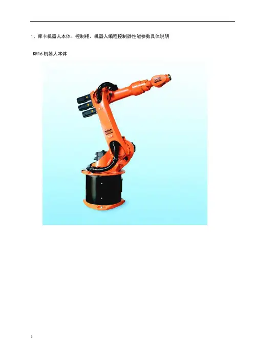
1、库卡机器人本体、控制柜、机器人编程控制器性能参数具体说明 KR16机器人本体KR16的外形尺寸及工作范围KR16性能参数负载(指第6轴最前端P点负载)16公斤手臂/第1轴转盘负载10/20 公斤总负载46公斤运动轴数6法兰盘(第6轴上)DIN ISO 9409-1-A50安装位置地面/墙壁/天花板重复精度+/控制器KRC2自重235公斤作业空间范围立方米每个轴的运动参数运动范围运动速度轴1+/-185°156°/s 轴2+35°/-155°156°/s 轴3+154°/ -130°156°/s 轴4+/-350°330°/s轴5+/-130°330°/s轴6+/-350°615°/s机器人控制器KRC2(1)机器人控制器KRC2外形尺寸控制柜采用高强材料作为结构框架,内部器件布置简洁明了,全部采用总线形式,维护方便、可靠;控制柜内的冷却按欧洲标准设计制造,元器件与冷却回路隔开,冷却可靠,外部灰层不会进入控制柜内部。
(2)KRC2性能参数库卡机器人特点库卡机器人由肘节式结构的机器人本体,KRC2控制柜、示教控制器KCP组成;铝合金机器人本体、高速运动曲线的动态模型优化,使得库卡机器人的加速性能比其它普通机器人高出25%,有利于提高系统寿命、优化工作节拍;KRC2控制柜采用熟悉的个人电脑WINDOWS操作界面,中英文多种语言菜单;标准的工业计算机,硬盘、光驱、软驱、打印接口、I/O信号、多种总线接口,远程诊断;KCP具有示教、编程、安全保护功能;控制系统具有绝对位置记忆、软PLC(选项)功能;事故间隔时间长达7万小时---这是其它机器人所无法比拟的。
库卡工业机器人优点描述:(1)标准六轴工业机器人本体:合理的机械结构和紧凑化设计6个自由度AC伺服马达绝对位置编码器所有轴都带有抱闸特定的负载和运动惯量的设计,使得速度和运动特性达到最优化臂部的附加负载对额定负载没有运动限制本体和控制器之间7m长电缆, 并可根据需要进行扩展特点描述:模块化的机械结构设计,任何部分都可迅速更换高精度电子零点标定,任何人在任何时间所作的零点标定都是相同的,标定后,程序无需重新校正即可进入生产状态。
机器人KR6; KR16 维护保养手册维护保养操作指导不含腕部轴发行发行::2008-02-20 版本 版本::05 1 of 17版权:KUKA机器人有限公司该文件或引用,在没有得到版权所有者的允许,不可以复制或透露给第三方;与维护无关的功能描述,没有体现在该文件中,在控制系统说明文件中可以找到;我们检查了该文件内容与所描述的软件、硬件的一致性;然而不排除有差异性,此文件信息受定期检查,必要的修正会在今后的版本中。
2 of 17目 录1 概述2 润滑油更换2.1 主轴齿轮变速箱润滑油更换2.1.1 第一轴齿轮变速箱润滑油更换2.1.2 第二轴齿轮变速箱润滑油更换2.1.3 第三轴齿轮变速箱润滑油更换3 其他维护4 清洁和预防性维护5 使用润滑油的安全防范措施3 of 17适合以下型号机器人的维护:必须遵守相关的安全准则!对于“EX”系列机器人,维护必须是在无爆炸危险的环境下进行!对于“CR”系列机器人,维护或清洁工作必须是在清洁室外进行,在维护前,所有可能妨碍维护工作的部件,都应该拆除;润滑脂的更换,是在特殊指定维护间隔时间,或机器人开始工作5年后进行,以先到时间为准。
正常维护间隔时间为机器人工作2万小时;第一次的维护(润滑油更换),是在机器人工作2万小时,或者机器人开始工作5年后进行,以先到时间为准。
规则:润滑脂的更换,每隔5年要进行一次;润滑油的密封圈也是如此。
在机器人的“技术台表”中,应该填写有关机器人的维护时间。
当机器人的使用环境与规定的不一致时(例如灰尘很大,湿度很高,环境温度很高),有关维护问题需要咨询KUKA的设计部门。
4 of 17符号说明维护位置维护位置,在图上可明显看到的维护位置,在图上被隐藏住的润滑油更换,指定的维护间隔时间标示更换润滑油的容积拧紧螺丝/螺母检查或更换齿形皮带目视检查可将维护方法描述分成几个步骤并标以数字顺序展示出来。
被标示“三角警示”或“手阻止符号”的维护命令,必需要紧随上一步骤明显地能被看见,这些特殊标示命令大多和上一步骤的操作有关。
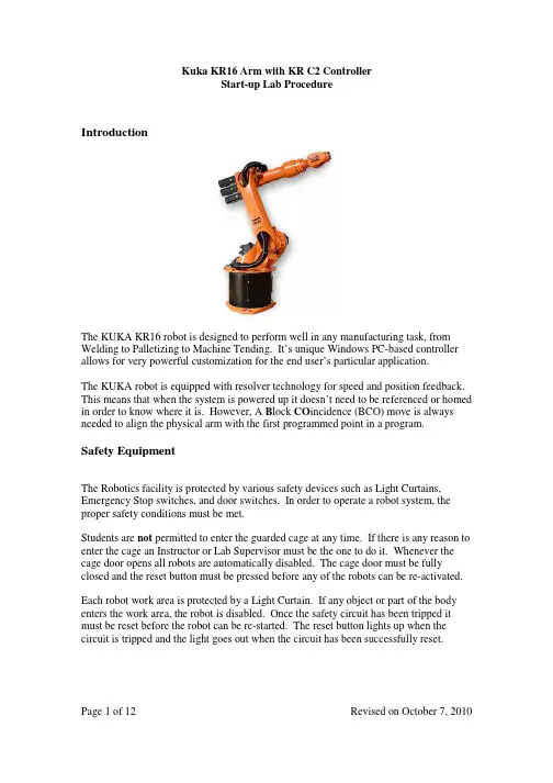
Start-up Lab ProcedureIntroductionThe KUKA KR16 robot is designed to perform well in any manufacturing task, from Welding to Palletizing to Machine Tending. It’s unique Windows PC-based controller allows for very powerful customization for the end user’s particular application.The KUKA robot is equipped with resolver technology for speed and position feedback. This means that when the system is powered up it doesn’t need to be referenced or homed in order to know where it is. However, A B lock CO incidence (BCO) move is always needed to align the physical arm with the first programmed point in a program.Safety EquipmentThe Robotics facility is protected by various safety devices such as Light Curtains, Emergency Stop switches, and door switches. In order to operate a robot system, the proper safety conditions must be met.Students are not permitted to enter the guarded cage at any time. If there is any reason to enter the cage an Instructor or Lab Supervisor must be the one to do it. Whenever the cage door opens all robots are automatically disabled. The cage door must be fully closed and the reset button must be pressed before any of the robots can be re-activated. Each robot work area is protected by a Light Curtain. If any object or part of the body enters the work area, the robot is disabled. Once the safety circuit has been tripped it must be reset before the robot can be re-started. The reset button lights up when the circuit is tripped and the light goes out when the circuit has been successfully reset.Start-up Lab ProcedureHuman-Machine InterfaceThe Kuka Control Panel (KCP2) handheld controller has many “Soft Keys” or “Programmable Keys”. These are buttons that are positioned around the display screen. The current function of each button is displayed on the screen and changes dynamically to suit the needs of the operation. The paragraphs below describe the physical layout of the KCP; refer to the screen shot of the display itself for an example of the types of function that could be shown on the screen.The top row keys are referred to as Menu Keys. They are used to open menus, while the Arrow keys and Enter key (lower right) are used to navigate through the menus.The keys on the left and right sides of the screen are Status Keys. They are used for selecting operating options, switching individual functions and setting values. Their current function is displayed on the screen.Start-up Lab ProcedureThe keys at the bottom of the screen are called Softkeys. They are used for a wide range of functions and operations.When selecting any key or function it may result in the display of a “popup” message window or menu window. The Escape key (yellow - top left) will usually close these windows. Use the Cursor arrow keys to select menu items and the Enter key to register your choice. Pressing Enter will sometimes complete an operation and sometime it will open a new menu window for further choices.The Window Selection key (blue – top left) is used to move the focus from one open window to the next. Usually the Softkeys and status keys will have different functions in different windows.Finally, there is a full QWERTY keyboard and Numeric keypad along the bottom of the handheld unit.Procedure to Turn OnTurn On1.Turn on the external computer (on top of the control cabinet.)2. Release three Emergency Stop buttons(one on the Robot Controller front panel,one on the Teach Pendant, and one on theSafety circuit control panel.) by turningthem and allowing them to pop out.3. Turn main power switch on4. The Windows Operating System will start.Even after the Display is on, wait for theMessage: “DSE – Boot Finished” to showin the message window.5. Press the bottom row Softkey “Ackn. All”6. If there is a message that says “ExternalEmergency Stop Pressed”, then reset the Safety Circuit (light curtain reset). 7.If there is a message that says“EMERGENCY STOP”, then reset the E-STOP buttons on the KRC2 controller or the KCP2 teach pendant (make sure they’repopped out).8. Press the bottom row Softkey “Ackn. All”If the message window is not focused andthis Softkey is not available, press the PageKey (blue) to select the message windowbefore “Ackn. All”.Start-up Lab ProcedureProcedure to Test Various Manual Motion Modes9. Press the blue Page key to select the main part of the window. This may show a current program being run or edited, or it may show a File Manager. 10. If a program is shown in Edit mode press“Close”, then “Yes” to save changes. If a program is shown in Run mode, press“NAVIGATOR”, then “Deselect”. Youshould now see the File Manager screen.Joint Mode1. Use the Mode Select key (directly under theJog Select key) to toggle between Run mode(picture of a runner) and Single Step Mode(picture of 2 walkers.) Leave the setting on Single Step .2. Use the Coordinate Select key (on the Right Side) to toggle between Joint, Tool, RobotBase, and World coordinate systems. Leavethe setting on Joint. 3. Hold the Enabling Switch (Live Man) on the back of the KCP. The I indicator on theMessage Window will turn Green when the drive contactor has been initialized.4. Use the +/- status keys to move the 6 axeslabelled A1, A2, A3, A4, A5 and A6.Press the Jog Select key (Top Left Status Key) to toggle between Key Jog, Mouse Jog and No Jog (Run Mode). Leave the setting on Key Jog . Set the key switch on the control panel to T2 mode. Set the Hand Override (HOV) speed to 30%.Start-up Lab ProcedureProcedure to create a New Job and teach a simple programWorld Mode1. Set the Coordinate Select key to WorldCoordinates.2. Hold the Enabling Switch.3. Use the +/- status keys to move the 6 coordinatedirections labelled X, Y, Z, A, B and C.4.The origin of the coordinate system is on the floorat the center of the robot base.Robot Base Mode 1. The Robot Base coordinate system is currently setexactly the same as the World Coordinates.Tool Mode1. Set the Coordinate Select key to Tool Coordinates.2. Hold the Enabling Switch.3. Use the +/- status keys to move the 6 coordinatedirections labelled X, Y, Z, A, B and C.4. Notice how the origin of the coordinates is the tipof the tool rather than the base of the robot. Create a New Job 1. Make sure the display shows the File Management screen. 2. Use the Page Key to Focus on the File Management screen. 3. Use the right cursor and left cursor buttons (arrow keys) to move the highlighted cursor between the Folder Window on the Left side and the FileWindow on the Right side. Leave the cursor in the File Window.4. Press the Softkey “New” at the bottom of the display.5. Use the keyboard keys to type in a program name and then press Enter.Start-up Lab ProcedureTeach a simple program (using newly created job)Press the Softkey “Select” at the bottom of the display. The program file will display in “Select” (Run) mode. VERY IMPORTANT: In Selectmode the robot can be moved, pointstaught and previous points revisited.Gripper commands can also be entered.However, program commands cannotbe entered in this mode. You mustswitch to Edit mode to entercommands for things like I/O and FlowControl.1. Using the Cursor (arrow) keys, place the cursor onthe first line that starts “PTP HOME...”2. Hold the Live Man switch and the green “RunForward” button. If the robot is moving too slowly,note that “Programming Override” (POV) appliesfor this type of motion.3. With the arm positioned at the HOME position, usethe Coordinate Select Key to switch to Joint mode.Rotate the A5 axis in the + direction until the gripperis oriented straight down.4. Press the Softkey “Motion” to start the process ofsaving a location.5. To navigate the “Inline Form” use the arrow keysand the “Option Select” Status key (bottom key onthe right side of the display.)6. For the first location use the following settingsa. PTP (point to point, or Joint-type Motion)b. P# (Location name, automatically indexes foreach saved location.) See Note about Framesdata.c. Blank (Options are CONT (continuous, lowaccuracy) or blank (full accuracy)).d. Vel = 100%e. PDAT# (do not change anything)Start-up Lab Procedure7.Press Enter to register the saved location. You canuse the Softkey “Change” at any time to recall theinline form and change the parameters.Operating the Gripper1.To operate the gripper manually, use the Status Key on the Left side of thedisplay. Note the Live-man switch must be activated to enable the gripperto operate.2.To insert gripper commands in the program, select the Technology Menu atthe top of the display, then select GripperTech, then select Gripper.e the following settings in the Inline Form:a.Gripper 1b.Select CLOSE or OPEN (use the Option Select Key again)c.Blank (the choices are CONT or blank)d.GDAT# (when the cursor is on GDAT, a new parameter windowwill open. Use the Page select key to focus on that window andchange the gripper delay time to about 2 seconds.)4.Press Enter to register the gripper command.AssignmentAfter creating the program initialization steps, save positions and gripper commands to simulate having the robot pick up a part from one location on the table and drop the part on a different location on the table.The assignment is to create a programmed sequence as follows:a.The robot moves from the Home or Reference position to a point inspace above an imaginary pickup positionb.Move down to the imaginary pickup positionc.Activate the gripper (closed)d.Move up to the same location saved previouslye.Move over to a point in space above an imaginary drop positionf.Move down to the imaginary drop positiong.De-activate the gripper (open)h.Move up to the same location saved previouslyi.Move back to the Reference location (program should start and endat the same location)This program must run in clear space. Do not attempt to use the fixtures provided for the robot until you are completing the second lab assignment!Kuka KR16 Arm with KR C2 Controller Start-up Lab ProcedureRun a Simple Program Step Mode1. Toggle Mode Select to Single Step mode2. Make sure the Screen is displaying the program inRun mode (selected).3. From the Program menu select “Reset Program”(the current step indicator arrow should be on theINI line.)4. Change the key switch on the controller to “Auto”mode.5. Clear all Emergency Stop messages.6. Press the “Drive On” button at the top of the KCP.The green “I” indicator should come on.7. Press the green “Run Forward” button and hold ituntil “Programmed Path Reached (BCO)” showsin the message window.8. Press and hold the Run Forward button for eachblock of the program.9. The program must be reset from the Program menubefore it can be run again.Automatic Mode10.Select Run Mode11.Follow all instructions as for Step Mode. 12. Press and hold the Run Forward button once to runthe entire program.13. The program must be reset from the Program menubefore it can be run again.Start-up Lab ProcedureSaving Jobs to Diskette or Flash DriveThe Kuka PC-Based controller is connected to an external computer using a Peer-to-peer network. The “Kuka Files” folder on the desktop is mapped to the X: drive in the Kuka File Manager. Because of limitations in the Kuka system, the external computer is sometimes not shown properly in the Kuka File Manager.IMPORTANT: The external computer must be turned on before the Kuka robot is powered up. This ensures that the File Manager displays the X: drive.When files are saved from the Kuka, they will appear in the Kuka Files folder on the external computer. From there they can be dragged to the Floppy Drive icon or the USB Key icon. Do not leave them on the computer – they will be erased!The following instructions are performed on the KCP handheld controller.To save files from the controller to your diskette1.Make sure the external computer is on and the WIN98 (X:\) drive is available2.In the Kuka File Manager, move the cursor to the file window containing yourprograms and use the SHIFT + Down Arrow keys to select files (save the .SRCand .DAT file for each program!)3.Select the EDIT menu at the top of the screen, then select COPY4.Select the WIN98 (X:\) drive, then move your cursor to the file window5.Select the EDIT menu, then select PASTETo bring files from your diskette back to the controller1.Transfer the files from your diskette or USB key to the Kuka Files folder on theexternal computer.2.Make sure the WIN98 (X:\) drive is available3.In the Kuka File Manager, Select the WIN98 (X:\) drive, then move your cursor tothe file window and use the SHIFT + Down Arrow keys to select files (remember to restore the .SRC and .DAT file for each program!)4.Select the EDIT menu at the top of the screen, then select COPY5.Move your cursor to Program folder, and then the file window6.Select the EDIT menu, then select PASTEStart-up Lab ProcedureSupplemental NotesProgramming different speedsOn the Kuka robot, the relative speed for each individual motion can be set as a percentage of total speed. In addition, there is a total speed override function that sets the maximum speed for all motions as a percentage of the actual highest speed. Example:PTP P1 Vel= 20% PDAT1 Tool[1] Base[1] sets the speed to 20% of the robot’s current top speed setting1.Move the cursor up or down to the line you wish to change2.Press the Softkey “Change” to open the inline form for the linee the arrow keys to select the speed setting4.Key in a new value for speed5.Press EnterProgramming the robot to check a sensorAn input device such as a Pushbutton Switch or a Sensor can be wired to a terminal in the robot control panel. When the sensor is activated the robot will receive a positive input. When the sensor is not activated the robot will not receive an input. The input terminals are numbered, starting at 1. The WAIT FOR command pauses the program until the specified input condition is met.Example:WAIT FOR $IN[1] pauses the program until Input #1 is ONWAIT FOR $IN[1] = = FALSE pauses the program until Input #1 is OFF1.Press the TECHNOLOGY Menu Key on the top right of the displaye the arrow keys to select HUMBER_CMDs then FREEFORM_COMMANDand finally FREEFORM3.Press Enter4.Type the command in the statement box5.Press Enter to insert the command in your programIn your program, the command will look like this:_Freeform_Command.Exec_ Statement: WAIT FOR $IN [1]Start-up Lab ProcedureProgramming a short delay in the robot programIn order to pause the robot program for a short amount of time, use the WAIT SEC command to wait for a specified number of seconds.Example:WAIT SEC 2 causes the program to pause for 2 seconds before continuing.1.Press the TECHNOLOGY Menu Key on the top right of the displaye the arrow keys to select HUMBER_CMDs then FREEFORM_COMMANDand finally FREEFORM3.Press Enter4.Type the command in the statement box5.Press Enter to insert the command in your programUsing Straight Line Path ControlArticulated Robots normally move more quickly and efficiently using Joint mode path control. However, this means that the path followed by the gripper is not a straight line. If the application requires a truly straight line, you must command the robot to move in a Straight Line (Linear) path.In the Kuka system, you command the arm to follow a straight line to a location by changing a motion type from PTP to LIN.1.Move the cursor up or down to the line you wish to change2.Press the Softkey “Change” to open the inline form for the linee the arrow keys to select the PTP/LIN settinge the “Option Select” Status key (bottom key on the right side of the display) tochange from PTP to LIN5.Adjust the speed setting if necessary6.Press EnterExample:LIN P1 Vel= 2m/s CDAT1 Tool[1] Base[1]Start-up Lab ProcedureUsing Continuous (CONT) Mode for Reduced Accuracy MotionsVery often the robot arm executes motions in the air on the way from one work point to another that do not require precision accuracy. Normally speed is more important for these motions. Changing the motion accuracy from blank to CONT tells the controller to “cut the corner” at the end of the motion, creating a quicker, but less accurate path.1.Move the cursor up or down to the line you wish to change2.Press the Softkey “Change” to open the inline form for the linee the arrow keys to select the blank / CONT settinge the “Option Select” Status key (bottom key on the right side of the display) tochange from blank to CONT5.Press Enter。

1、库卡机器人本体、控制柜、机器人编程控制器性能参数具体说明1.1 KR16机器人本体KR16的外形尺寸及工作范围KR16性能参数负载(指第6轴最前端P点负载)16公斤手臂/第1轴转盘负载10/20 公斤总负载46公斤运动轴数 6法兰盘(第6轴上)DIN ISO 9409-1-A50安装位置地面/墙壁/天花板重复精度+/-0.05mm控制器KRC2自重235公斤作业空间范围14.5立方米每个轴的运动参数运动范围运动速度轴1+/-185°156°/s轴2+35°/-155°156°/s轴3+154°/ -130°156°/s轴4+/-350°330°/s轴5+/-130°330°/s轴6+/-350°615°/s1.2机器人控制器KRC2(1)机器人控制器KRC2外形尺寸控制柜采用高强材料作为结构框架,内部器件布置简洁明了,全部采用总线形式,维护方便、可靠;控制柜内的冷却按欧洲标准设计制造,元器件与冷却回路隔开,冷却可靠,外部灰层不会进入控制柜内部。
(2)KRC2性能参数处理器 库卡(工业)计算机操作系统 微软WINDOWS XP编程及控制 库卡KCP设计生产标准DIN EN 292, DIN EN 418, DIN EN 614-1, DIN EN 775, DIN EN 954, DIN EN 50081-2, DIN EN 50082-2, DIN EN 60204-1保护等级 IP54 工作环境温度 0°-45° (如果工作环境温度超过45°,需加冷却设备)控制轴数 6-8个 自重 178公斤 输入电源 3x400V-10%∽3x415V+10% , 49-61赫兹负载功率 最大8KVA 保护熔断器 32A , 3只 (慢熔型)与外围设备通讯接口 Ether Net, DevicNet (Interbus, profibus 作为可选项)至机器人电缆总成 7米(可加长到 15米, 或 25、35、50米) 噪音等级(根据DIN 45635-1) 67dB性能参数尺寸(长x 高x 厚):330x260x35mm 保护等级:IP54 显示屏:640x480,256色LCD 彩显,VGA 模式 6D 空间鼠标,使示教动作容易操作 4种工作模式切换旋钮,方便操作与安全 3位人体学始能开关 中/英/德/法多种语言菜单切换容易 10米控制电缆 开始/停止/紧急停止按钮1.4 库卡机器人特点库卡机器人由肘节式结构的机器人本体,KRC2控制柜、示教控制器KCP组成;铝合金机器人本体、高速运动曲线的动态模型优化,使得库卡机器人的加速性能比其它普通机器人高出25%,有利于提高系统寿命、优化工作节拍;KRC2控制柜采用熟悉的个人电脑WINDOWS操作界面,中英文多种语言菜单;标准的工业计算机,硬盘、光驱、软驱、打印接口、I/O信号、多种总线接口,远程诊断;KCP具有示教、编程、安全保护功能;控制系统具有绝对位置记忆、软PLC(选项)功能;事故间隔时间长达7万小时---这是其它机器人所无法比拟的。
KUKA机器人介绍KR16嘿,朋友!今天咱们来聊聊这个超厉害的 KUKA 机器人 KR16 。
我记得有一次去一家工厂参观,那场景真的让我印象深刻。
一进车间,就看到 KR16 机器人在有条不紊地工作着。
它那灵活的机械臂,就像人类的手臂一样自如,但又比人类的手臂更加精准和有力。
KR16 机器人的外观设计就很酷炫。
它可不是那种笨笨的大块头,而是有着流畅线条和精致结构的“智能伙伴”。
它的主体颜色通常是醒目的工业橙或者稳重的灰色,给人一种专业又可靠的感觉。
KR16 的负载能力相当不错,能轻松应对各种任务。
比如说,它可以精准地抓取和搬运重物,而且速度还挺快,一点儿也不拖泥带水。
这就好比一个大力士,能举重若轻,轻松搞定那些对我们来说费劲的活儿。
再说说它的精度吧,那可真是一绝!我在参观的时候,亲眼看到它在组装零件,每个零件的安装位置都分毫不差,就像是被尺子量过一样准确。
这种精度,对于那些对质量要求极高的生产环节来说,简直是太重要了。
KR16 的灵活性也是值得一提的。
它能够在不同的工作场景中迅速适应,调整自己的动作和姿态。
就像一个优秀的舞者,能根据不同的音乐和舞台环境,跳出最完美的舞步。
而且,KR16 机器人的操作也不算太复杂。
工厂里的工人师傅们经过简单的培训就能上手,让它乖乖听话,按照指令完成各种任务。
这可给工厂节省了不少人力和时间成本呢。
KR16 还有着出色的稳定性。
在长时间的工作中,它很少出现故障,就像一个不知疲倦的“工作狂”,一直保持着高效的工作状态。
总之,KUKA 机器人 KR16 真的是个了不起的家伙。
它就像是工厂里的超级英雄,用自己的力量和智慧,为生产带来了更高的效率和更好的质量。
相信在未来,它会在更多的领域发挥作用,让我们的生活变得更加便捷和美好!回想那次参观,KR16 机器人工作的场景依然历历在目,也让我对科技的力量有了更深刻的认识。
库卡选型手册库卡选型手册一、引言本手册旨在向用户提供关于库卡的详细信息,帮助用户在选型过程中做出准确的决策。
本文档将介绍库卡的特点、技术规格、应用领域以及选型注意事项等内容。
二、库卡概述1.库卡的定义:库卡是一种自动化系统,能在工业生产线上完成各种任务,如物料搬运、装配、焊接等。
2.库卡的特点:高精度、高速度、可编程、安全性高、灵活性强等。
三、库卡技术规格1.类型:介绍不同类型的库卡,如SCARA、Delta、协作等。
2.载荷能力:能够承受的最大负载。
3.工作范围:的工作半径或工作空间尺寸。
4.重复定位精度:在重复动作过程中的定位精度。
5.运动速度:在不同轴向的最大运动速度。
6.控制系统:的控制器类型、通信接口等。
四、库卡应用领域1.汽车制造业:介绍库卡在汽车制造领域的应用,如焊接、喷涂、装配等。
2.电子制造业:介绍库卡在电子制造领域的应用,如半导体芯片的处理、电路板的组装等。
3.医疗行业:介绍库卡在医疗行业的应用,如手术辅助、药物分配等。
4.物流行业:介绍库卡在物流行业的应用,如包裹分拣、仓库管理等。
五、库卡选型注意事项1.任务需求:根据具体的应用需求,选择合适的类型和规格。
2.环境要求:考虑在工作环境中所需的温度、湿度、气体等环境因素。
3.安全性能:选型过程中需考虑的安全特性、安全设备等。
4.成本考虑:根据预算限制,选择成本适中的库卡。
附件:本文档附带以下附件:1.库卡技术规格表2.库卡应用案例集法律名词及注释:1.版权:指创作作品的著作权人对其作品享有的权利。
2.商标:指用于区分商品或服务的特殊标志、图形或文字。
3.专利:指对发明实施的独占权或独占权申请。
昆山华恒机器人焊接系统应用(二)昆山华恒焊接股份有限公司是国内领先的自动化焊接/切割系统供应商,作为国家级高新技术企业和江苏省焊接装备工程技术中心,华恒一直保持行业内的市场和技术领先地位,并以自身的技术实力和完善的服务保障体系服务于工程机械、机车车辆、煤矿机械、航空航天、军工、锅炉、石化、食品医药、管道建设、电力建设等行业。
华恒和世界著名的机器人厂商KUKA和FANUC强强合作,致力于中厚板结构件制造领域的机器人系统的应用和工艺推广,针对用户的具体情况量身定制,提供给用户性价比最高的焊接/切割机器人系统。
工程机械——挖掘机——马达座、导向座机器人焊接系统⏹8轴联动机器人焊接系统⏹KUKA-KR16机器人⏹两轴变位机最大负载1吨⏹量身定制的通用工装保证了最佳的完焊率⏹高效MIG/MAG焊接电源及完善的焊枪系统⏹完善的中厚板机器人焊接功能——焊缝寻位、电弧跟踪、多层多道、专家参数库、轨迹重现、TCP自动校正、多种横摆形式、坡口尺寸偏差修正、在线优化、三维模拟仿真、离线编程功能。
工程机械——挖掘机——油箱机器人焊接系统⏹8轴联动机器人焊接系统⏹KUKA-KR16机器人⏹两轴L型变位机负载1吨⏹量身定制的气动通用工装保证了最佳的完焊率⏹油箱焊缝一枪焊接完成,焊接过程不中断,极大的提升了产品质量⏹高效MIG/MAG焊接电源及完善的焊枪系统⏹完善的机器人焊接功能——焊缝寻位、电弧跟踪、专家参数库、轨迹重现、TCP自动校正、多种横摆形式、坡口尺寸偏差修正、在线优化、三维模拟仿真、离线编程功能。
工程机械——挖掘机——挖斗连结构件机器人焊接系统⏹8轴联动机器人焊接系统⏹FANUC-M-20ia机器人⏹两轴变位机负载500kg⏹量身定制的通用工装保证了最佳的完焊率⏹高效MIG/MAG焊接电源及完善的焊枪系统⏹完善的中厚板机器人焊接功能——焊缝寻位、电弧跟踪、多层多道、专家参数库、轨迹重现、TCP自动校正、多种横摆形式、坡口尺寸偏差修正、在线优化、三维模拟仿真、离线编程功能。
1、库卡机器人本体、控制柜、机器人编程控制器性能参数具体说明1.1 KR16机器人本体
KR16的外形尺寸及工作范围
KR16性能参数
负载(指第6轴最前端P点负载)16公斤
手臂/第1轴转盘负载10/20 公斤
总负载46公斤
运动轴数 6
法兰盘(第6轴上)DIN ISO 9409-1-A50
安装位置地面/墙壁/天花板
重复精度+/-0.05mm
控制器KRC2
自重235公斤
作业空间范围14.5立方米
每个轴的运动参数运动范围运动速度
轴1+/-185°156°/s
轴2+35°/-155°156°/s
轴3+154°/ -130°156°/s
轴4+/-350°330°/s
轴5+/-130°330°/s
轴6+/-350°615°/s
1.2机器人控制器KRC2
(1)机器人控制器KRC2外形尺寸
控制柜采用高强材料作为结构框架,内部器件布置简洁明了,全部采用总线形式,维护方便、可靠;控制柜内的冷却按欧洲标准设计制造,元器件与冷却回路隔开,冷却可靠,外部灰层不会进入控制柜内部。
(2)KRC2性能参数
1.4 库卡机器人特点
库卡机器人由肘节式结构的机器人本体,KRC2控制柜、示教控制器KCP组成;铝合金机器人本体、高速运动曲线的动态模型优化,使得库卡机器人的加速性能比其它普通机器人高出25%,有利于提高系统寿命、优化工作节拍;
KRC2控制柜采用熟悉的个人电脑WINDOWS操作界面,中英文多种语言菜单;标准的工业计算机,硬盘、光驱、软驱、打印接口、I/O信号、多种总线接口,远程诊断;
KCP具有示教、编程、安全保护功能;
控制系统具有绝对位置记忆、软PLC(选项)功能;
事故间隔时间长达7万小时---这是其它机器人所无法比拟的。
库卡工业机器人优点描述:
(1)标准六轴工业机器人本体:
⏹合理的机械结构和紧凑化设计
⏹6个自由度AC伺服马达
⏹绝对位置编码器
⏹所有轴都带有抱闸
⏹特定的负载和运动惯量的设计,使得速度和运动特性达到最优化
⏹臂部的附加负载对额定负载没有运动限制
⏹本体和控制器之间7m长电缆, 并可根据需要进行扩展
⏹特点描述:
●模块化的机械结构设计,任何部分都可迅速更换
●高精度电子零点标定,任何人在任何时间所作的零点标定都
是相同的,标定后,程序无需重新校正即可进入生产状态。
●可调机械手臂,更大的活动空间和柔韧性
●高速运动曲线中动态模型的优化,加速性能高于普通机器人25%,更利于
提高系统寿命、优化工作节拍。
(2). 库卡机器人控制器KRC2
●标准的工业控制计算机PENTIU处理器
●基于Windows平台的操作系统,可在线选择多种语言(包括中文)
●支持多种标准工业控制总线,包括:Interbus、Profibus、Devicenet、Canbus、
Controlnet、EtherNet、Remote I/O等;Devicenet、EtherNet为标准配置。
●标准的ISA、PCI插槽,方便扩展。
可直接插入各种标准Modem接入高速Internet,实
现远程监控和诊断。
●采用高级语言编程
●标准的控制软件功能包,可适应于各种应用
●6D运动控制鼠标,方便运动轨迹的示教
●断电自动重启,不需重新进入程序
●系统设示波器功能,可方便进行错误诊断和系统优化
◆库卡标准的工业控制PC
◆.基本配置:
CPU:2.0 GHZ
内存:512MB RAM
硬盘:20G
串口:COM1、COM2 、COM3,9针或15针
标准并口和打印机接口
主板:标准工业控制计算机主板,含PCI、ISA插槽
USB接口
标准CD-ROM和软驱
标准显卡,可外接显示器
◆优点:
●开放性好,能够直接和多种功能卡直接插接,方便扩展,通用性好
●程序可方便进行备份及恢复,而且可在短时间内完成
●可直接外接显示器、鼠标和键盘,方便程序的读写
●可随时进行系统的更新
●大容量硬盘,对程序指令基本无限制,并可长期存储相关操作和系统日志
●支持多种总线协议,与总线接口板连接方便,即插即用
●一旦出现系统错误,可在最短时间内恢复
●可方便进行联网,易于监控和管理
●拆卸方便、易于维护
(3) .库卡控制编程器
●LCD彩显,VGA模式,640X480, 256色
●6D空间鼠标,示教过程简单方便
●三位使能开关、易于安全操作
●四种工作模式,可根据实际需要任意选择
●通过Canbus 与PC通讯,实时性更强。