MAX6347UR34中文资料
- 格式:pdf
- 大小:159.68 KB
- 文档页数:8

3m6348技术参数
3m6348技术参数
3m6348是一款高性能的电子产品,其技术参数如下:
1. 尺寸:长100mm,宽50mm,高20mm
2. 重量:100g
3. 电池容量:2000mAh
4. 屏幕尺寸:3.5英寸
5. 屏幕分辨率:320*240
6. 操作系统:Android
7.0
7. 处理器:四核1.3GHz
8. 存储容量:16GB
9. 扩展存储:支持最大128GB的Micro SD卡
10. 摄像头:前置200万像素,后置500万像素
11. 网络支持:2G、3G、4G
12. Wi-Fi:支持802.11 b/g/n
13. 蓝牙:支持4.0
14. GPS:支持
15. 传感器:重力感应器、光线感应器、距离感应器、指纹识别器
16. 其他功能:支持FM收音、录音、音乐播放、视频播放、电子书阅读等
3m6348是一款功能齐全、性能优异的电子产品,其屏幕分辨率高、
处理器快速、存储容量大,能够满足用户对于高效、便捷、多功能的
需求。
同时,3m6348还支持多种网络和连接方式,如2G、3G、4G、Wi-Fi、蓝牙等,用户可以随时随地与外界保持联系。
此外,3m6348
还配备了多种传感器,如重力感应器、光线感应器、距离感应器、指
纹识别器等,能够为用户提供更加智能、便捷的使用体验。
总之,3m6348是一款功能强大、性能优异的电子产品,其技术参数的优越性能和多样化的功能,能够满足用户对于高效、便捷、多功能的需求,是一款值得推荐的电子产品。


目录产品特点: (2)应用: (2)描述: (2)规格: (3)引脚结构: (5)绝对最大额定值: (5)典型性能曲线:在T A = 25°C,V S =±15V,除非另有说明。
(6)应用信息: (9)输出电流: (9)热保护: (9)功耗: (10)输入特性: (10)带宽控制PIN: (10)提高运算放大器的输出电流: (10)高频应用: (11)封装形式 (14)产品特点:●高输出电流:250mA●转换速度:2000 v / μs●PIN所选带宽:30MHz到180MHz●低静态电流:1.5mA(30MHz的带宽)●电源范围:±2.25〜±18V●内部电流可限制●过热关断保护●8引脚DIP,SO-8,5引脚TO-220,5引脚DDPAK表面贴装应用:●阀驱动●电磁驱动器●运算放大器电流升压●线路驱动器●耳机驱动器●视频驱动程序●电机驱动器●测试设备●ATE引脚驱动器描述:BUF634是一种高速开环单位增益缓冲器,适用范围广的应用中建议。
它可用于运算放大器的反馈环路内,以增加输出电流,消除热反馈,并提高容性负载驱动。
对于低功耗应用,BUF634静态电流1.5mA具有250mA输出,2000V/μs摆率和30MHz 带宽。
V-和BW引脚之间连接一个电阻,可以调整带宽从30MHz到180MHz。
输出电路完全由内部电流限制和热关断,使其坚固耐用和易于使用的保护。
BUF634可在多种封装形式,以适应机械和功耗要求。
类型包括8引脚DIP,SO-8表面贴装,5引脚TO-220,采用5引脚DDPAK表面贴装塑料功率封装。
规格:(在T A = 25°C,V S =±15V,除非另有说明)引脚结构:绝对最大额定值:供应电压................................................ ..................................... ±18V 输入电压范围............................................... ................................ ±V S 输出短路(接地).......................................... .......连续工作温度................................................ ..... -40°C至125°C储存温度................................................ ........ -55°C至125°C结温................................................ ....................... 150°C铅温度(焊接,10s)........................................... ......... 300°C典型性能曲线:在T A = 25°C,V S =±15V,除非另有说明。


BusWorks900PB系列PROFIBUS / RS485网络I / O模块技术参考ACROMAG INCORPORATED电话:(248)624-154130765南威克瑟姆路传真:(248)624-9234邮政信箱BOX437威克瑟姆,MI48393-7037 U.S.A.版权所有2002年,Acromag,Inc.在美国印刷。
数据和规格如有变更,恕不另行通知。
8500-698-A02M000目录关于PROFIBUS。
(3)PROFIBUS DP从站状态机.. (7)电源开/复位状态 (7)参数状态.......................................。
7I / O配置状态.......................................。
7数据交换状态..........................................。
8故障安全操作..................... .. (8)看门狗................................. .. ..................... ..9GSD文件...........................................................10.... 需要的软件... .. .................. (13)传输的类型.................. (14)SRD和发送请求数据瓦特/确认...... ..14SDN发送数据瓦特/无应答....................14. .. PROFIBUS DP数据字符格式...............。
14数据的ProfiBus错误检查............。
............... ..15 PROFIBUS报文结构........................ ..15起始定界符............................................16.......。

6N134中⽂资料FeaturesDual Marked with Device Part Number and DSCC Drawing NumberManufactured and Tested on a MIL-PRF-38534 Certified LineQML-38534, Class H and K Five Hermetically Sealed Package Configurations Performance Guaranteed over -55°C to +125°C ? High Speed: 10 M Bit/sCMR: > 10,000 V/µs Typical 1500 Vdc Withstand Test Voltage2500 Vdc Withstand Test Voltage for HCPL-565X High Radiation Immunity 6N137, HCPL-2601, HCPL-2630/-31 Function Compatibility ? Reliability DataTTL Circuit CompatibilityApplicationsMilitary and SpaceHigh Reliability SystemsTransportation, Medical, and Life Critical SystemsLine ReceiverVoltage Level ShiftingIsolated Input Line Receiver Isolated Output Line Driver Logic Ground Isolation Harsh Industrial EnvironmentsIsolation for Computer,Communication, and Test Equipment SystemsDescriptionThese units are single, dual and quad channel, hermetically sealed optocouplers. The products are capable of operation and storage over the full military temperature range and can be purchased as either standard product or with full MIL-PRF-38534 Class Level H or K testing or from the appropri-ate DSCC Drawing. All devices are manufactured and tested on a MIL-PRF-38534 certified line and are included in the DSCC Quali-fied Manufacturers List QML-38534 for Hybrid Microcircuits.Quad channel devices areavailable by special order in the 16 pin DIP through hole packages.Truth Table(Positive Logic)Multichannel DevicesInput Output On (H)L Off (L)HFunctional DiagramMultiple Channel Devices AvailableSingle Channel DIP Input Enable Output On (H)H L Off (L)H H On (H)L H Off (L)LH*See matrix for available extensions.Hermetically Sealed, High Speed,High CMR, Logic Gate Optocouplers Technical Data6N134*81028HCPL-563X HCPL-663X HCPL-565X 5962-98001HCPL-268K HCPL-665X 5962-90855HCPL-560XCAUTION: It is advised that normal static precautions be taken in handling and assembly of this component to prevent damage and/or degradation which may be induced by ESD.V CC V OUTV E GNDThe connection of a 0.1 µF bypass capacitor between V CC and GND is recommended.Selection Guide–Package Styles and Lead Configuration OptionsPackage16 Pin DIP 8 Pin DIP 8 Pin DIP 8 Pin DIP 16 Pin Flat Pack 20 Pad LCCC Lead Style Through Hole Through Hole Through Hole Through Hole Unformed Leads Surface MountChannels 212242Common Channel V CC , GND None V CC , GND V CC , GND V CC , GND None WiringWithstand Test Voltage 1500 Vdc 1500 Vdc 1500 Vdc 2500 Vdc 1500 Vdc 1500 Vdc Agilent Part # & Options Commercial6N134*HCPL-5600HCPL-5630HCPL-5650HCPL-6650HCPL-6630MIL-PRF-38534, Class H 6N134/883BHCPL-5601HCPL-5631HCPL-5651HCPL-6651HCPL-6631MIL-PRF-38534, Class K HCPL-268K HCPL-560K HCPL-563K HCPL-665K HCPL-663K Standard Lead Finish Gold Plate Gold Plate Gold Plate Gold Plate Gold PlateSolder PadsSolder Dipped Option #200Option #200Option #200Option #200Butt Cut/Gold Plate Option #100Option #100Option #100Gull Wing/Soldered Option #300Option #300Option #300Class H SMD Part #Prescript for all below None 5962-None None None None Either Gold or Solder 8102801EX 9085501HPX 8102802PX 8102805PX 8102804FX 81028032XGold Plate 8102801EC 9085501HPC 8102802PC 8102805PC 8102804FCSolder Dipped 8102801EA 9085501HPA 8102802PA 8102805PA81028032A Butt Cut/Gold Plate 8102801UC 9085501HYC 8102802YC Butt Cut/Soldered 8102801UA 9085501HYA 8102802YA Gull Wing/Soldered 8102801TA 9085501HXA8102802ZA Class K SMD Part #Prescript for all below 5962-5962-5962-5962-5962-Either Gold or Solder 9800101KEX 9085501KPX 9800102KPX 9800104KFX 9800103K2XGold Plate 9800101KEC 9085501KPC 9800102KPC 9800104KFCSolder Dipped 9800101KEA 9085501KPA 9800102KPA 9800103K2AButt Cut/Gold Plate 9800101KUC 9085501KYC 9800102KYC Butt Cut/Soldered 9800101KUA 9085501KYA 9800102KYA Gull Wing/Soldered9800101KTA 9085501KXA 9800102KZA*JEDEC registered part.Each channel contains a GaAsP light emitting diode which isoptically coupled to an integrated high speed photon detector. The output of the detector is an open collector Schottky clamped transistor. Internal shields provide a guaranteed common mode transient immunityspecification of 1000 V/µs. For Isolation Voltage applications requiring up to 2500 Vdc, the HCPL-5650 family is also available. Package styles for these parts are 8 and 16 pin DIP through hole (case outlines P andE respectively), and 16 pin surface mount DIP flat pack(case outline F), leadless ceramic chip carrier (case outline 2).Devices may be purchased with a variety of lead bend and plating options. See Selection Guide Table for details. Standard Microcircuit Drawing (SMD)parts are available for each package and lead style.Because the same electrical die (emitters and detectors) are used for each channel of each device listed in this data sheet, absolute maximum ratings, recommended operating conditions, electrical specifications, and performance characteristics shown in the figures are identical for all parts.Occasional exceptions exist due to package variations and limitations,and are as noted. Additionally, the same package assembly processes and materials are used in all devices. These similarities give justification for the use of data obtained from one part torepresent other parts’ performance for reliability and certain limited radiation test results.Outline Drawings16 Pin DIP Through Hole, 2 ChannelsFunctional DiagramsNote: All DIP and flat pack devices have common V CC and ground. Single channel DIP has an enable pin 7. LCCC (leadless ceramic chip carrier) package has isolated channels with separate VCC and ground connections. All diagrams are “top view.”Leaded Device MarkingLeadless Device MarkingNOTE: DIMENSIONS IN MILLIMETERS (INCHES).COMPLIANCE INDICATOR,*DATE CODE, SUFFIX (IF NEEDED)COUNTRY OF MFR.Agilent CAGE CODE*Agilent DESIGNATORDSCC SMD*PIN ONE/ ESD IDENTAgilent P/N DSCC SMD** QUALIFIED PARTS ONLYCOMPLIANCE INDICATOR,*DATE CODE, SUFFIX (IF NEEDED)DSCC SMD*Agilent CAGE CODE*Agilent DESIGNATORCOUNTRY OF MFR.Agilent P/N PIN ONE/ ESD IDENTDSCC SMD** QUALIFIED PARTS ONLYOutline Drawings (continued)16 Pin Flat Pack, 4 Channels8 Pin DIP Through Hole, 2 Channels 2500 Vdc Withstand Test Voltage20 Terminal LCCC Surface Mount,2Channels8 Pin DIP Through Hole, 1 and 2 Channels0.36 (0.014)NOTE: DIMENSIONS IN MILLIMETERS (INCHES).2.29 (0.090) 2.79 (0.110)NOTE: DIMENSIONS IN MILLIMETERS (INCHES).NOTE: DIMENSIONS IN MILLIMETERS (INCHES).NOTE: DIMENSIONS IN MILLIMETERS (INCHES). SOLDER THICKNESS 0.127 (0.005) MAX.Hermetic Optocoupler OptionsRecommended Operating ConditionsParameterSymbol Min.Max.Units Input Current, Low Level, Each Channel I FL 0250µA Input Current, High Level, Each Channel*I FH 1020mA Supply Voltage, OutputV CC 4.55.5VFan Out (TTL Load) Each ChannelN6*Meets or exceeds DSCC SMD and JEDEC requirements.Absolute Maximum Ratings(No derating required up to +125°C)Storage Temperature Range, T S ...................................-65°C to +150°C Operating Temperature, T A..........................................-55°C to +125°C Case Temperature, T C ................................................................+170°C Junction Temperature, T J ...........................................................+175°C Lead Solder Temperature ...............................................260°C for 10 s Peak Forward Input Current, I F PK , (each channel,≤1 ms duration)......................................................................40 mA Average Input Forward Current, I F AVG (each channel)................20 mA Input Power Dissipation (each channel).....................................35 mW Reverse Input Voltage, V R (each channel).........................................5 V Supply Voltage, V CC (1 minute maximum)........................................7 V Output Current, I O (each channel)...............................................25 mA Output Power Dissipation (each channel). (40)mW Output Voltage, V O (each channel)..................................................7 V*Package Power Dissipation, P D (each channel)........................200 mW*Selection for higher output voltages up to 20 V is available.Single Channel Product OnlyEmitter Input Voltage, V E ...............................................................5.5 VNote enable pin 7. An external 0.01 µF to 0.1 µF bypass capacitor must be connected between V CC and ground for each package type.8 Pin Ceramic DIP Single Channel SchematicESD Classification(MIL-STD-883, Method 3015)HCPL-5600/01/0K ...............................................................(?), Class 16N134, 6N134/883B, HCPL-5630/31/3K, HCPL-5650/51, HCPL-6630/31/3K and HCPL-6650/51/5K.......................(Dot), Class 3Electrical Characteristics (T= -55°C to +125°C, unless otherwise specified)*Identified test parameters for JEDEC registered parts.**All typical values are at V CC = 5 V , T A = 25°C. Recommended Operating Conditions (cont’d.)Single Channel Product Only [10]ParameterSymbol Min.Max.Units High Level Enable Voltage V EH 2.0V CC V Low Level Enable VoltageV EL0.8VElectrical Characteristics, (Contd.) T= -55°C to +125°C unless otherwise specifiedSingle Channel Product Only Low Level I EL V CC = 5.5 V,1, 2, 3-1.45-2.0mA Enable Current V E = 0.5 V High Level V EH 1, 2, 3 2.0V10Enable Voltage Low Level V EL 1, 2, 30.8VEnable Voltage*Identified test parameters for JEDEC registered part.**All typical values are at V CC = 5 V , T A = 25°C.Typical Characteristics, T = 25°C, V = 5 VDual and Quad Channel Product Only Input-Input I I-I 0.5nA Relative Humidity = 45%4Leakage CurrentV I-I = 500 V, t = 5 s Resistance (Input-Input)R I-I 1012V I-I = 500 V 4Capacitance (Input-Input)C I-I0.55pF f = 1 MHz4Notes:1. Each channel.2. All devices are considered two-terminal devices; I I-O is measured between all input leads or terminals shorted together and alloutput leads or terminals shorted together.3. Measured between each input pair shorted together and all output connections for that channel shorted together.4. Measured between adjacent input pairs shorted together for each multichannel device.5. t PHL propagation delay is measured from the 50% point on the leading edge of the input pulse to the 1.5 V point on the leadingedge of the output pulse. The t PLH propagation delay is measured from the 50% point on the trailing edge of the input pulse to the1.5 V point on the trailing edge of the output pulse.6. The HCPL-6630, HCPL-6631, and HCPL-663K dual channel parts function as two independent single channel units. Use the singlechannel parameter limits for each channel.7. CM L is the maximum rate of rise of the common mode voltage that can be sustained with the output voltage in the logic low state(V O < 0.8 V). CM H is the maximum rate of fall of the common mode voltage that can be sustained with the output voltage in the logic high state (V O > 2.0 V).8. This is a momentary withstand test, not an operating condition.9. It is essential that a bypass capacitor (0.01 to 0.1 µF, ceramic) be connected from V CC to ground. Total lead length between bothends of this external capacitor and the isolator connections should not exceed 20 mm.10. No external pull up is required for a high logic state on the enable input.11. The t ELH enable propagation delay is measured from the 1.5 V point on the trailing edge of the enable input pulse to the 1.5 Vpoint on the trailing edge of the output pulse.12. The t EHL enable propagation delay is measured from the 1.5 V point on the leading edge of the enable input pulse tothe 1.5 Vpoint on the leading edge of the output pulse.13. Standard parts receive 100% testing at 25°C (Subgroups 1 and 9). SMD and 883B parts receive 100% testing at 25, 125, and-55°C (Subgroups 1 and 9, 2 and 10, 3 and 11, respectively).14. Parameters are tested as part of device initial characterization and after design and process changes. Parameters are guaranteedto limits specified for all lots not specifically tested.15. Not required for 6N134, 6N134/883B, 8102801, HCPL-268K and 5962-9800101 types.16. Required for 6N134, 6N134/883B, 8102801, HCPL-268K and 5962-9800101 types.17. Not required for HCPL-5650, HCPL-5651 and 8102805 types.18. Required for HCPL-5650, HCPL-5651 and 8102805 types only.Figure 1. High Level Output Currentvs. Temperature.5 VV O * C L INCLUDES PROBE AND STRAY WIRING CAPACITANCE. Figure 4. Test Circuit for t PHL and t PLH .*I +5 V OUTPUT V O MONITORING NODEFigure 7. Test Circuit for Common Mode Transient Immunity and Typical Waveforms.11OUTPUT V OMONITORINGNODET A = +125 °C* ALL CHANNELS TESTED SIMULTANEOUSLY.V CCI O = 25 mAFigure 10. Operating Circuit for Burn-In and Steady State Life Tests. Figure 8. Test Circuit for t EHL and t ELH.Figure 9. Enable Propagation Delayvs. Temperature.MIL-PRF-38534 Class H,Class K, and DSCC SMDTest ProgramAgilent’s Hi-Rel Optocouplers arein compliance with MIL-PRF-38534 Classes H and K. Class Hand Class K devices are also incompliance with DSCC drawings81028, 5962-90855 and 5962-98001.Testing consists of 100% screen-ing and quality conformanceinspection to MIL-PRF-38534./doc/4e2d970a03d8ce2f006623a8.htmlData subject to change.Copyright ? 1999 Agilent TechnologiesObsoletes 5968-4743E5968-9407E (10/00)。


54/74374八上升沿D触发器(3S,时钟输入有回环特性)简要说明:374为具有三态输出的八D边沿触发器,共有54/74S374和54/74LS374两种线路结构型式,其主要电器特性的典型值如下(不同厂家具体值有差别):型号f m P D54S374/74S374 100MHz 450mW54LS374/74LS374 50MHz 135mW374的输出端O0~O7可直接与总线相连。
当三态允许控制端OE为低电平时,O0~O7为正常逻辑状态,可用来驱动负载或总线。
当OE为高电平时,O0~O7呈高阻态,即不驱动总线,也不为总线的负载,但锁存器内部的逻辑操作不受影响。
当时钟端CP脉冲上升沿的作用下,O随数据D而变。
由于CP端施密特触发器的输入滞后作用,使交流和直流噪声抗扰度被改善400mV。
引出端符号:D0~D7 数据输入端OE 三态允许控制端(低电平有效)CP 时钟输入端O0~O7 输出端外部管腿图:逻辑图:真值表:极限值:电源电压 (7V)输入电压5.5V54/74S374…………………………….………….7V 54/74LS374…………………………………….输出高阻态时高电平电压 …………………………. 5.5V工作环境温度54XXX ………………………………….-55~125℃0~70℃74XXX ………………………………….存储温度 …………………………………………. -65~150℃推荐工作条件:54/74374 54/74LS374单位最小额定最大最小额定最大54 4.5 5 5.5 4.5 5 5.5V 电源电压Vcc74 4.75 5 5.25 4.75 5 5.25输入高电平电压V iH 2 2 V54 0.8 0.7V输入低电平电压V iL74 0.8 0.854 -2 -1mA输出高电平电流I OH74 -6.5 -2.654 20 12mA输出低电平电流I OL74 20 24CP(H) 6 15ns脉冲宽度t wCP(L) 7.3 15保持时间t H D 2↓0↓ns建立时间t set D 5↓20↓ns静态特性(TA 为工作环境温度范围)S374 LS374 参 数 测 试 条 件【1】最小 最大 最小 最大单位V IK 输入嵌位电压 Vcc=最小,I ik =-18mA-1.5 -1.5 V V OH 输出高电平电压 Vcc =最小,V IL =最大,V IH =2V ,I OH =最大2.4 2.4 V 54 0.5 0.4 V OL 输出低电平电压 Vcc=最小,V IL =最大,V IH =2V,I OL =最大74 0.5 0.5 V V I =5.5V 1 I I 最大输入电压时输入电流Vcc =最大 V I =7V 0.1 mA V IL =0.5V -0.25 I IL 输入低电平电流 Vcc =最大, V IL =0.4V -0.4mA I IH输入高电平电流 Vcc =最大,V IH =2.7V50 20 uA I OS 输出短路电流 Vcc =最大-40 -100 -30 -130 mA Icc 电源电流 Vcc =最大,OE 接4.5V140 40 mA V 0=2.4V 50 I OZH 输出高阻态时高电平电流 Vcc =最大,V IH =2V V 0=2.7V20 mA V 0=0.5V -50 I OZL 输出高阻态时低电平电流 Vcc =最大,V IH =2V V 0=0.4V-20 mA [1]: 测试条件中的“最小”和“最大”用推荐工作条件中的相应值。

查看文章常见运放型号2008-05-13 17:54CA3130 高输入阻抗运算放大器 Intersil[DATA]CA3140 高输入阻抗运算放大器CD4573 四可编程运算放大器 MC14573ICL7650 斩波稳零放大器LF347(NS[DATA]) 带宽四运算放大器 KA347LF351 BI-FET单运算放大器 NS[DATA]LF353 BI-FET双运算放大器 NS[DATA]LF356 BI-FET单运算放大器 NS[DATA]LF357 BI-FET单运算放大器 NS[DATA]LF398 采样保持放大器 NS[DATA]LF411 BI-FET单运算放大器 NS[DATA]LF412 BI-FET双运放大器 NS[DATA]LM124 低功耗四运算放大器(军用档) NS[DATA]/TI[DATA] LM1458 双运算放大器 NS[DATA]LM148 四运算放大器 NS[DATA]LM224J 低功耗四运算放大器(工业档) NS[DATA]/TI[DATA] LM2902 四运算放大器 NS[DATA]/TI[DATA]LM2904 双运放大器 NS[DATA]/TI[DATA]LM301 运算放大器 NS[DATA]LM308 运算放大器 NS[DATA]LM308H 运算放大器(金属封装) NS[DATA]LM318 高速运算放大器 NS[DATA]LM324(NS[DATA]) 四运算放大器 HA17324,/LM324N(TI)LM348 四运算放大器 NS[DATA]LM358 NS[DATA] 通用型双运算放大器 HA17358/LM358P(TI) LM380 音频功率放大器 NS[DATA]LM386-1 NS[DATA] 音频放大器 NJM386D,UTC386LM386-3 音频放大器 NS[DATA]LM386-4 音频放大器 NS[DATA]LM3886 音频大功率放大器 NS[DATA]LM3900 四运算放大器LM725 高精度运算放大器 NS[DATA]LM733 带宽运算放大器LM741 NS[DATA] 通用型运算放大器 HA17741MC34119 小功率音频放大器NE5532 高速低噪声双运算放大器 TI[DATA]NE5534 高速低噪声单运算放大器 TI[DATA]NE592 视频放大器OP07-CP 精密运算放大器 TI[DATA]OP07-DP 精密运算放大器 TI[DATA]TBA820M 小功率音频放大器 ST[DATA]TL061 BI-FET单运算放大器 TI[DATA]TL062 BI-FET双运算放大器 TI[DATA]TL064 BI-FET四运算放大器 TI[DATA]TL072 BI-FET双运算放大器 TI[DATA]TL074 BI-FET四运算放大器 TI[DATA]TL081 BI-FET单运算放大器 TI[DATA]TL082 BI-FET双运算放大器 TI[DATA]TL084 BI-FET四运算放大器 TI[DATA]AD824 JFET输入,单电源,低电压,低功耗,精密四运算放大器 MC33171 单电源,低电压,低功耗运算放大器AD826 低功耗,宽带,高速双运算放大器 MC33172 单电源,低电压,低功耗双运算放大器AD827 低功耗,高速双运算放大器 MC33174 单电源,低电压,低功耗四运算放大器AD828 低功耗,宽带,高速双运算放大器 MC33178 大电流,低功耗,低噪音双运算放大器AD844 电流反馈型,宽带,高速运算放大器 MC33179 大电流,低功耗,低噪音四运算放大器AD846 电流反馈型,高速,精密运算放大器 MC33181 JFET输入,低功耗运算放大器AD847 低功耗,高速运算放大器 MC33182 JFET输入,低功耗双运算放大器AD8531 COMS单电源,低功耗,高速运算放大器 MC33184 JFET输入,低功耗四运算放大器AD8532 COMS单电源,低功耗,高速双运算放大器 MC33201 单电源,大电流,低电压运算放大器AD8534 COMS单电源,低功耗,高速四运算放大器 MC33202 单电源,大电流,低电压双运算放大器AD9617 低失真,电流反馈型,宽带,高速,精密运算放大器 MC33204 单电源,大电流,低电压四运算放大器AD9631 低失真,宽带,高速运算放大器 MC33272 单电源,低电压,高速双运算放大器AD9632 低失真,宽带,高速运算放大器 MC33274 单电源,低电压,高速四运算放大器AN6550 低电压双运算放大器 MC33282 JFET输入,宽带,高速双运算放大器AN6567 大电流,单电源双运算放大器 MC33284 JFET输入,宽带,高速四运算放大器AN6568 大电流,单电源双运算放大器 MC33502 BIMOS,单电源,大电流,低电压,双运算放大器BA718 单电源,低功耗双运算放大器 MC34071A 单电源,高速运算放大器BA728 单电源,低功耗双运算放大器 MC34072A 单电源,高速双运算放大器CA5160 BIMOS,单电源,低功耗运算放大器 MC34074A 单电源,高速四运算放大器CA5260 BIMOS,单电源双运算放大器 MC34081 JFET输入,宽带,高速运算放大器CA5420 BIMOS,单电源,低电压,低功耗运算放大器 MC34082 JFET输入,宽带,高速双运算放大器CA5470 BIMOS单电源四运算放大器 MC34084 JFET输入,宽带,高速四运算放大器CLC400 电流反馈型,宽带,高速运算放大器 MC34181 JFET输入,低功耗运算放大器CLC406 电流反馈型,低功耗,宽带,高速运算放大器 MC34182 JFET输入,低功耗双运算放大器CLC410 电流反馈型,高速运算放大器 MC34184 JFET输入,低功耗四运算放大器CLC415 电流反馈型,宽带,高速四运算放大器 MC35071A 单电源,高速运算放大器CLC449 电流反馈型,宽带,高速运算放大器 MC35072A 单电源,高速双运算放大器CLC450 电流反馈型,单电源,低功耗,宽带,高速运算放大器 MC35074A 单电源,高速四运算放大器CLC452 单电源,电流反馈型,大电流,低功耗,宽带,高速运算放大器 MC35081 JFET输入,宽带,高速运算放大器CLC505 电流反馈型,高速运算放大器 MC35082 JFET输入,宽带,高速双运算放大器EL2030 电流反馈型,宽带,高速运算放大器 MC35084 JFET输入,宽带,高速四运算放大器EL2030C 电流反馈型,宽带,高速运算放大器 MC35171 单电源,低电压,低功耗运算放大器EL2044C 单电源,低功耗,高速运算放大器 MC35172 单电源,低电压,低功耗双运算放大器EL2070 电流反馈型,宽带,高速运算放大器 MC35174 单电源,低电压,低功耗四运算放大器EL2070C 电流反馈型,宽带,高速运算放大器 MC35181 JFET输入,低功耗运算放大器EL2071C 电流反馈型,宽带,高速运算放大器 MC35182 JFET输入,低功耗双运算放大器EL2073 宽带,高速运算放大器 MC35184 JFET输入,低功耗四运算放大器EL2073C 宽带,高速运算放大器 MM6558 低电压,低失调电压,精密双运算放大器EL2130C 电流反馈型,宽带,高速运算放大器 MM6559 低电压,低失调电压,精密双运算放大器EL2150C 单电源,宽带,高速运算放大器 MM6560 低电压,低失调电压,精密双运算放大器EL2160C 电流反馈型,宽带,高速运算放大器 MM6561 低功耗,低电压,低失调电压,精密双运算放大器EL2165C 电流反馈型,宽带,高速,精密运算放大器 MM6564 单电源,低电压,低功耗,低失调电压,精密双运算放大器EL2170C 单电源,电流反馈型,低功耗,宽带,高速运算放大器 MM6572 低噪音,低电压,低失调电压,精密双运算放大器EL2175C 电流反馈型,宽带,高速,精密运算放大器 NE5230 单电源,低电压运算放大器EL2180C 单电源,电流反馈型,低功耗,宽带,高速运算放大器 NE5512 通用双运算放大器EL2224 宽带,高速双运算放大器 NE5514 通用四运算放大器EL2224C 宽带,高速双运算放大器 NE5532 低噪音,高速双运算放大器EL2232 电流反馈型,宽带,高速双运算放大器 NE5534 低噪音,高速运算放大器EL2232C 电流反馈型,宽带,高速双运算放大器 NJM2059 通用四运算放大器EL2250C 单电源,宽带,高速双运算放大器 NJM2082 JFET输入,高速双运算放大器EL2260C 电流反馈型,宽带,高速双运算放大器 NJM2107 低电压,通用运算放大器EL2270C 单电源,电流反馈型,低功耗,宽带,高速双运算放大器 NJM2112 低电压,通用四运算放大器EL2280C 单电源,电流反馈型,低功耗,宽带,高速双运算放大器 NJM2114 低噪音双运算放大器EL2424 宽带,高速四运算放大器 NJM2115 低电压,通用双运算放大器EL2424C 宽带,高速四运算放大器 NJM2119 单电源,精密双运算放大器EL2444C 单电源,低功耗,高速四运算放大器 NJM2122 低电压,低噪音双运算放大器EL2450C 单电源,宽带,高速四运算放大器 NJM2130F 低功耗运算放大器EL2460C 电流反馈型,宽带,高速四运算放大器 NJM2132 单电源,低电压,低功耗双运算放大器EL2470C 单电源,电流反馈型,低功耗,宽带,高速四运算放大器 NJM2136 低电压,低功耗,宽带,高速运算放大器EL2480C 单电源,电流反馈型,低功耗,宽带,高速四运算放大器 NJM2137 低电压,低功耗,宽带,高速双运算放大器HA-2640 高耐压运算放大器 NJM2138 低电压,低功耗,宽带,高速四运算放大器HA-2645 高耐压运算放大器 NJM2140 低电压双运算放大器HA-2839 宽带,高速运算放大器 NJM2141 大电流,低电压双运算放大器HA-2840 宽带,高速运算放大器 NJM2147 高耐压,低功耗双运算放大器HA-2841 宽带,高速运算放大器 NJM2162 JFET输入,低功耗,高速双运算放大器HA-2842 宽带,高速运算放大器 NJM2164 JFET输入,低功耗,高速四运算放大器HA-4741 通用四运算放大器 NJM3404A 单电源,通用双运算放大器HA-5020 电流反馈型,宽带,高速运算放大器 NJM3414 单电源,大电流双运算放大器HA-5127 低噪音,低失调电压,精密运算放大器 NJM3415 单电源,大电流双运算放大器HA-5134 低失调电压,精密四运算放大器 NJM3416 单电源,大电流双运算放大器HA-5137 低噪音,低失调电压,高速,精密运算放大器 NJM4556A 大电流双运算放大器HA-5142 单电源,低功耗双运算放大器 NJM4580 低噪音双运算放大器HA-5144 单电源,低功耗四运算放大器 NJU7051 CMOS单电源,低功耗,低电压,低失调电压运算放大器HA-5177 低失调电压,精密运算放大器 NJU7052 CMOS单电源,低功耗,低电压,低失调电压双运算放大器HA-5221 低噪音,精密运算放大器 NJU7054 CMOS单电源,低功耗,低电压,低失调电压四运算放大器HA-5222 低噪音,精密双运算放大器 NJU7061 CMOS单电源,低功耗,低电压,低失调电压运算放大器HA-7712 BIMOS,单电源,低功耗,精密运算放大器 NJU7062 CMOS单电源,低功耗,低电压,低失调电压双运算放大器HA-7713 BIMOS,单电源,低功耗,精密运算放大器 NJU7064 CMOS单电源,低功耗,低电压,低失调电压四运算放大器HA16118 CMOS单电源,低电压,低功耗双运算放大器 NJU7071 CMOS单电源,低功耗,低电压,低失调电压运算放大器AD704 低偏置电流,低功耗,低失调电压,精密四运算放大器 MAX430 CMOS单电源运算放大器AD705 低偏置电流,低功耗,低失调电压,精密运算放大器 MAX432 CMOS单电源运算放大器AD706 低偏置电流,低功耗,低失调电压,精密双运算放大器 MAX4330 单电源,低电压,低功耗运算放大器AD707 低失调电压,精密运算放大器 MAX4332 单电源,低电压,低功耗双运算放大器AD708 低失调电压,精密双运算放大器 MAX4334 单电源,低电压,低功耗四运算放大器AD711 JFET输入,高速,精密运算放大器 MAX473 单电源,低电压,宽带,高速运算放大器AD712 JFET输入,高速,精密双运算放大器 MAX474 单电源,低电压,宽带,高速双运算放大器AD713 JFET输入,高速,精密四运算放大器 MAX475 单电源,低电压,宽带,高速四运算放大器AD744 JFET输入,高速,精密运算放大器 MAX477 宽带,高速运算放大器AD745 JFET输入,低噪音,高速运算放大器 MAX478 单电源,低功耗,精密双运算放大器AD746 JFET输入,高速,精密双运算放大器 MAX478A 单电源,低功耗,精密双运算放大器AD795 JFET输入,低噪音,低功耗,精密运算放大器 MAX479 单电源,低功耗,精密四运算放大器AD797 低噪音运算放大器 MAX479A 单电源,低功耗,精密四运算放大器AD8002 电流反馈型,低功耗,宽带,高速双运算放大器 MAX480 单电源,低功耗,低电压,低失调电压,精密运算放大器AD8005 电流反馈型,低功耗,宽带,高速双运算放大器 MAX492C 单电源,低功耗,低电压,精密双运算放大器AD8011 电流反馈型,低功耗,宽带,高速运算放大器 MAX492E 单电源,低功耗,低电压,精密双运算放大器AD8031 单电源,低功耗,高速运算放大器 MAX492M 单电源,低功耗,低电压,精密双运算放大器AD8032 单电源,低功耗,高速双运算放大器 MAX494C 单电源,低功耗,低电压,精密四运算放大器AD8041 单电源,宽带,高速运算放大器 MAX494E 单电源,低功耗,低电压,精密四运算放大器AD8042 单电源,宽带,高速双运算放大器 MAX494M 单电源,低功耗,低电压,精密四运算放大器AD8044 单电源,宽带,高速四运算放大器 MAX495C 单电源,低功耗,低电压,精密运算放大器AD8047 宽带,高速运算放大器 MAX495E 单电源,低功耗,低电压,精密运算放大器AD8055 低功耗,宽带,高速运算放大器 MAX495M 单电源,低功耗,低电压,精密运算放大器AD8056 低功耗,宽带,高速双运算放大器 MC1458 通用双运算放大器AD8072 电流反馈型,宽带,高速双运算放大器 MC1458C 通用双运算放大器AD812 电流反馈型,低电压,低功耗,高速双运算放大器 MC33071A 单电源,高速运算放大器AD817 低功耗,宽带,高速运算放大器 MC33072A 单电源,高速双运算放大器AD818 低功耗,宽带,高速运算放大器 MC33074A 单电源,高速四运算放大器AD820 JFET输入,单电源,低电压,低功耗,精密运算放大器 MC33078 低噪音双运算放大器AD822 JFET输入,单电源,低电压,低功耗,精密双运算放大器 MC33079 低噪音四运算放大器AD823 JFET输入,单电源,低电压,低功耗,精密,高速双运算放大器 MC33102 低功耗双运算放大器HA16119 CMOS单电源,低电压,低功耗双运算放大器 NJU7072 CMOS单电源,低功耗,低电压,低失调电压双运算放大器HFA1100 电流反馈型,宽带,高速运算放大器 NJU7074 CMOS单电源,低功耗,低电压,低失调电压四运算放大器HFA1120 电流反馈型,宽带,高速运算放大器 OP-07 低漂移,精密运算放大器HFA1205 电流反馈型,低功耗,宽带,高速双运算放大器 OP-113 BICMOS单电源,低噪音,低失调电压,精密运算放大器HFA1245 电流反馈型,低功耗,宽带,高速双运算放大器 OP-150 COMS,单电源,低电压,低功耗ICL7611 CMOS低电压,低功耗运算放大器 OP-160 电流反馈型,高速运算放大器ICL7612 CMOS低电压,低功耗运算放大器 OP-162 单电源,低电压,低功耗,高速,精密运算放大器ICL7621 CMOS低电压,低功耗双运算放大器 OP-177 低失调电压,精密运算放大器ICL7641 CMOS低电压四运算放大器 OP-183 单电源,宽带运算放大器ICL7642 CMOS低电压,低功耗四运算放大器 OP-184 单电源,低电压,高速,精密运算放大器ICL7650S 稳压器 OP-191 单电源,低电压,低功耗运算放大器LA6500 单电源,功率OP放大器 OP-193 单电源,低电压,低功耗,精密运算放大器LA6501 单电源,功率OP放大器 OP-196 单电源,低电压,低功耗运算放大器LA6510 2回路单电源功率OP放大器 OP-200 低功耗,低失调电压,精密双运算放大器"LA6512 高压,功率OP放大器双运算放大器 OP-213 BICMOS单电源,低噪音,低失调电压,精密双运算放大器LA6513 高压,功率OP放大器双运算放大器 OP-250 COMS,单电源,低电压,低功耗双运算放大器LA6520 单电源,功率OP放大器三运算放大器 OP-260 电流反馈型,高速双运算放大器LF356 JFET输入,高速运算放大器 OP-262 单电源,低电压,低功耗,高速,精密双运算放大器LF356A JFET输入,高速运算放大器 OP-27 低噪音,低失调电压,精密运算放大器LF411 JFET输入,高速运算放大器 OP-270 低噪声,低失调电压,精密双运算放大器LF411A JFET输入,高速运算放大器 OP-271 精密双运算放大器LF412 JFET输入,高速双运算放大器 OP-275 高速双运算放大器LF412A JFET输入,高速双运算放大器 OP-279 单电源,大电流双运算放大器LF441 低功耗,JFET输入运算放大器 OP-282 JFET输入,低功耗双运算放大器LF441A 低功耗,JFET输入运算放大器 OP-283 单电源,宽带双运算放大器LF442 低功耗,JFET输入双运算放大器 OP-284 单电源,低电压,高速,精密双运算放大器LF442A 低功耗,JFET输入双运算放大器 OP-290 单电源,低功耗,精密双运算放大器LF444 低功耗,JFET输入四运算放大器 OP-291 单电源,低电压,低功耗双运算放大器LF444A 低功耗,JFET输入四运算放大器 OP-292 BICMOS单电源,通用双运算放大器LM2902 单电源四运算放大器 OP-293 单电源,低电压,低功耗,精密双运算放大器LM2904 单电源双运算放大器 OP-295 BICMOS低功耗,精密双运算放大器LM324 单电源四运算放大器 OP-296 单电源,低电压,低功耗双运算放大器LM358 单电源双运算放大器 OP-297 低电压,低功耗,低漂移,精密双运算放大器LM4250 单程控、低功耗运算放大器 OP-37 低噪音,低失调电压,高速,精密运算放大器LM607 低失调电压,精密运算放大器 OP-400 低功耗,低失调电压,精密四运算放大器LM6118 宽带,高速双运算放大器 OP-413 BICMOS单电源,低噪音,低失调电压,精密四运算放大器。
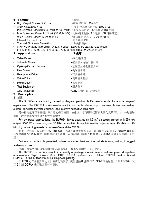
1 Feature 1特点•High Output Current: 250 mA•高输出电流:250毫安•Slew Rate: 2000 V/µs •摆率(电压转换速率):2000 V /µS•Pin-Selected Bandwidth: 30 MHz to 180 MHz •引脚选择带宽:30兆赫至180兆赫•Low Quiescent Current: 1.5 mA (30 MHz BW) •低静态输出电流:1.5毫安(30兆赫带宽)•Wide Supply Range: ±2.25 to ±18 V •宽电压供应范围:2.25至18伏•Internal Current Limit •内部电流限制•Thermal Shutdown Protection •热关机保护•8-Pin PDIP, SOIC-8, 5-Lead TO-220, 5-Lead DDPAK-TO-263 Surface-Mount•8引脚PDIP,SOIC - 8、5引脚TO - 220,5引脚ddpak-to-263表面贴装2 Applications 2应用•Valve Driver •阀门驱动器•Solenoid Driver•螺线管(电磁)驱动器•Op Amp Current Booster•运算放大器电流放大器•Line Driver•线路驱动器•Headphone Driver•耳机驱动器•Video Driver•视频驱动程序•Motor Driver •电机驱动•Test Equipment•测试设备•ATE Pin Driver•ATE自测引脚驱动程序3 Description3 描述The BUF634 device is a high speed, unity-gain open-loop buffer recommended for a wide range of applications. The BUF634 device can be used inside the feedback loop of op amps to increase output current, eliminate thermal feedback, and improve capacitive load drive.是一种高速开环增益缓冲器广泛的应用范围中的建议,它可用于运算放大器的反馈环路内,一起增加输出电流消除热反馈和改善容性负载驱动。

1/9July 2001IRF634IRF634FPN-CHANNEL 250V - 0.38Ω - 8A TO-220/TO-220FPMESH OVERLAY™ MOSFETs TYPICAL R DS (on) = 0.38 Ωs EXTREMELY HIGH dv/dt CAPABILITY s100% AVALANCHE TESTEDDESCRIPTIONUsing the latest high voltage MESH OVERLAY ™process, STMicroelectronics has designed an ad-vanced family of power MOSFETs with outstanding performance. The new patented STrip layout cou-pled with the Company’s proprietary edge termina-tion structure, makes it suitable in coverters for lighting applications.APPLICATIONSs HIGH CURRENT, HIGH SPEED SWITCHING s SWITH MODE POWER SUPPLIES (SMPS)s DC-DC CONVERTERS FOR TELECOM, INDUSTRIAL, AND LIGHTING EQUIPMENT s IDEAL FOR MONITOR’s B+ FUNCTIONABSOLUTE MAXIMUM RATINGS(•)Pulse width limited by safe operating areaTYPE V DSS R DS(on)I D IRF634IRF634FP250 V 250 V< 0.45 Ω< 0.45 Ω8 A 8 ASymbol ParameterValueUnit IRF634IRF634FPV DS Drain-source Voltage (V GS = 0)250VV DGR Drain-gate Voltage (R GS = 20 k Ω)250V V GS Gate- source Voltage± 20V I D Drain Current (continuos) at T C = 25°C 88(*)A I D Drain Current (continuos) at T C = 100°C 55(*)A I DM (q )Drain Current (pulsed)3232(*)A P TOT Total Dissipation at T C = 25°C 8030W Derating Factor0.640.24W/°C dv/dt (1)Peak Diode Recovery voltage slope 5V/ns V ISO Insulation Withstand Voltage (DC)-2000V T stg Storage Temperature–65 to 150°C T jMax. Operating Junction Temperature150°C(1) I SD ≤ 8A, di/dt ≤300 A/µs, V DD ≤ V (BR)DSS , Tj ≤T jMAX (*)Limited only by maximum temperature allowedIRF634/IRF634FP2/9THERMAL DATAAVALANCHE CHARACTERISTICSELECTRICAL CHARACTERISTICS (TCASE = 25 °C UNLESS OTHERWISE SPECIFIED)OFFON (1)DYNAMICTO-220TO-220FP Rthj-case Thermal Resistance Junction-case Max 1.564.11°C/W Rthj-ambThermal Resistance Junction-ambient Max62.5°C/W T lMaximum Lead Temperature For Soldering Purpose300°CSymbol ParameterMax ValueUnit I AR Avalanche Current, Repetitive or Not-Repetitive (pulse width limited by T j max)8A E ASSingle Pulse Avalanche Energy(starting T j = 25 °C, I D = I AR , V DD = 50 V)300mJSymbol ParameterTest ConditionsMin.Typ.Max.Unit V (BR)DSS Drain-sourceBreakdown Voltage I D = 250 µA, V GS = 0250V I DSS Zero Gate VoltageDrain Current (V GS = 0)V DS = Max Rating1µA V DS = Max Rating, T C = 125 °C 10µA I GSSGate-body Leakage Current (V DS = 0)V GS = ±20V±100nASymbol ParameterTest ConditionsMin.Typ.Max.Unit V GS(th)Gate Threshold Voltage V DS = V GS , I D = 250µA 234V R DS(on)Static Drain-source On ResistanceV GS = 10V, I D = 4 A0.380.45ΩSymbol ParameterTest ConditionsMin.Typ.Max.Unit g fs (1)Forward Transconductance V DS > I D(on) x R DS(on)max, I D =4A78S C iss Input Capacitance V DS = 25V, f = 1 MHz, V GS = 0770pF C oss Output Capacitance 118pF C rssReverse Transfer Capacitance48pF3/9IRF634/IRF634FPELECTRICAL CHARACTERISTICS (CONTINUED)SWITCHING ONSWITCHING OFFSOURCE DRAIN DIODENote: 1.Pulsed: Pulse duration = 300 µs, duty cycle 1.5 %.2.Pulse width limited by safe operating area.Symbol ParameterTest ConditionsMin.Typ.Max.Unit t d(on)Turn-on Delay Time V DD = 125 V, I D = 4 A R G =4.7Ω V GS = 10 V (see test circuit, Figure 3)13ns t r Rise Time 18ns Q g Total Gate Charge V DD = 200V, I D = 8 A,V GS = 10V3751.8nC Q gs Gate-Source Charge 5.2nC Q gdGate-Drain Charge14.8nCSymbol ParameterTest ConditionsMin.Typ.Max.Unit t d(Voff)t f Turn-off- Delay Time Fall TimeV DD = 125V, I D = 4 A, R G =4.7Ω, V GS = 10V (see test circuit, Figure 3)5116ns ns t r(Voff)t f t cOff-voltage Rise Time Fall TimeCross-over TimeV clamp = 200V, I D = 8 A, R G =4.7Ω, V GS = 10V (see test circuit, Figure 5)12.512.528ns ns nsSymbol ParameterTest ConditionsMin.Typ.Max.Unit I SD Source-drain Current 8A I SDM (2)Source-drain Current (pulsed)32A V SD (1)Forward On Voltage I SD = 8 A, V GS = 0 1.7V t rr Reverse Recovery Time I SD = 8 A, di/dt = 100A/µs V DD = 30V, T j = 150°C (see test circuit, Figure 5)198ns Q rr Reverse Recovery Charge 1.1µC I RRMReverse Recovery Current11.3AIRF634/IRF634FP4/9Output Characteristics5/9IRF634/IRF634FPIRF634/IRF634FP6/9Fig. 5: Test Circuit For Inductive Load Switching And Diode Recovery TimesFig. 4: Gate Charge test CircuitFig. 2: Unclamped Inductive WaveformFig. 1:Unclamped Inductive Load Test CircuitFig. 3: Switching Times Test Circuit ForResistive LoadIRF634/IRF634FP7/9IRF634/IRF634FP8/9IRF634/IRF634FPInformation furnished is believed to be accurate and reliable. However, STMicroelectronics assumes no responsibility for the consequencesof use of such information nor for any infringement of patents or other rights of third parties which may result from its use. No license is granted by implication or otherwise under any patent or patent rights of STMicroelectronics. Specification mentioned in this publication are subject to change without notice. This publication supersedes and replaces all information previously supplied. STMicroelectronics productsare not authorized for use as critical components in life support devices or systems without express written approval of STMicroelectronics.The ST logo is a trademark of STMicroelectronics© 2001 STMicroelectronics – Printed in Italy – All Rights ReservedSTMicroelectronics GROUP OF COMPANIESAustralia - Brazil - China - Finland - France - Germany - Hong Kong - India - Italy - Japan - Malaysia - Malta - Morocco -Singapore - Spain - Sweden - Switzerland - United Kingdom - U.S.A.9/9。

MAX3483,MAX3485,MAX3486,MAX3488,MAX3490以及MAX3491是用于RS-485与RS-422通信的3.3V,低功耗收发器,每个器件中都具有一个驱动器和一个接收器。
MAX3483和MAX3488具有限摆率驱动器,可以减小EMI,并降低由不恰当的终端匹配电缆引起的反射,实现最高250kbps的无差错数据传输。
MAX3486的驱动器摆率部分受限,可以实现最高2.5Mbps的传输速率。
MAX3485,MAX3490和MAX3491则可以实现最高10Mbps 的传输速率。
驱动器具有短路电流限制,并可以通过热关断电路将驱动器输出置为高阻状态,防止过度的功率损耗。
接收器输入具有失效保护特性,当输入开路时,可以确保逻辑高电平输出。
特性●半双工●速率:10Mbps●限摆率:NO●接收允许控制:YES●关断电流:2nA●引脚数:8参数暂无MAX3485的参数信息引脚图与功能MAX3485ESA品牌厂家:Maxim Integrated(美信),MAX3485ESA 渠道分销商:2家,现货库存数量:1542 PCS,MAX3485ESA价格参考:¥8.121元。
Maxim Integrated(美信)MAX3485ESA参数(SOIC 8Pin 3V 10Mbps,封装:SOIC),MAX3485ESA中文资料和引脚图及功能表说明书PDF下载(17页,409KB),您可以在MAX3485ESA接口芯片规格书Datesheet数据手册中,查到MAX3485ESA引脚图及功能的应用电路图电压和使用方法,MAX3485ESA典型电路教程。
MAX3485ESA可以用什么代替?代换型号如:MAX3485CSA+T、MAX3485CSA替代换,MAX3485ESA芯片系列中文手册中包含MAX3485ESA各引脚定义说明介绍及MAX3485ESA引脚功能图解,用户中文手册MAX3485ESA芯片手册PDF下载(17页,409KB)。

General DescriptionThe MAX6314 low-power CMOS microprocessor (µP)supervisory circuit is designed to monitor power supplies in µP and digital systems. The MAX6314’s RESET output is bidirectional, allowing it to be directly connected to µPs with bidirectional reset inputs, such as the 68HC11. It provides excellent circuit reliability and low cost by eliminating external components and adjustments. The MAX6314 also provides a debounced manual reset input.This device performs a single function: it asserts a reset signal whenever the V CC supply voltage falls below a preset threshold or whenever manual reset is asserted.Reset remains asserted for an internally programmed interval (reset timeout period) after V CC has risen above the reset threshold or manual reset is deasserted.The MAX6314 comes with factory-trimmed reset threshold voltages in 100mV increments from 2.5V to 5V. Preset timeout periods of 1ms, 20ms, 140ms,and 1120ms (minimum) are also available. The device comes in a SOT143 package.F or a µP supervisor with an open-drain reset pin, see the MAX6315 data sheet.________________________ApplicationsComputers ControllersIntelligent InstrumentsCritical µP and µC Power Monitoring Portable/Battery-Powered EquipmentFeatures♦Small SOT143 Package♦RESET Output Simplifies Interface to Bidirectional Reset I/Os♦Precision Factory-Set V CC Reset Thresholds:100mV Increments from 2.5V to 5V♦±1.8% Reset Threshold Accuracy at T A = +25°C ♦±2.5% Reset Threshold Accuracy Over Temp.♦Four Reset Timeout Periods Available: 1ms, 20ms, 140ms, or 1120ms (minimum) ♦Immune to Short V CC Transients ♦5µA Supply Current♦Pin-Compatible with MAX811MAX6314*68HC11/Bidirectional-CompatibleµP Reset Circuit________________________________________________________________Maxim Integrated Products1Pin ConfigurationTypical Operating Circuit19-1090; Rev 2; 12/05Ordering Information continued at end of data sheet.*Patents PendingFor pricing, delivery, and ordering information,please contact Maxim/Dallas Direct!at 1-888-629-4642, or visit Maxim’s website at .Ordering Information†The MAX6314 is available in a SOT143 package, -40°C to+85°C temperature range.††The first two letters in the package top mark identify the part,while the remaining two letters are the lot tracking code.Devices are available in both leaded and lead-free packaging.Specify lead-free by replacing “-T” with “+T” when ordering.M A X 631468HC11/Bidirectional-Compatible µP Reset Circuit 2_______________________________________________________________________________________ABSOLUTE MAXIMUM RATINGSELECTRICAL CHARACTERISTICS(V CC = +2.5V to +5.5V, T A = -40°C to +85°C, unless otherwise noted. Typical values are at T A = +25°C.)Stresses beyond those listed under “Absolute Maximum Ratings” may cause permanent damage to the device. These are stress ratings only, and functional operation of the device at these or any other conditions beyond those indicated in the operational sections of the specifications is not implied. Exposure to absolute maximum rating conditions for extended periods may affect device reliability.Note 1:The MAX6314 monitors V CC through an internal, factory-trimmed voltage divider that programs the nominal reset threshold.Factory-trimmed reset thresholds are available in 100mV increments from 2.5V to 5V (see Ordering and Marking Information ).Note 2:This is the minimum time RESET must be held low by an external pull-down source to set the active pull-up flip-flop.Note 3:Measured from RESET V OL to (0.8 x V CC ), R LOAD = ∞.V CC ........................................................................-0.3V to +6.0V All Other Pins..............................................-0.3V to (V CC + 0.3V)Input Current (V CC ).............................................................20mA Output Current (RESET )......................................................20mA Rate of Rise (V CC )...........................................................100V/µsContinuous Power Dissipation (T A = +70°C)SOT143 (derate 4mW/°C above +70°C).......................320mW Operating Temperature Range ...........................-40°C to +85°C Storage Temperature Range.............................-65°C to +160°C Lead Temperature (soldering, 10sec).............................+300°CMAX631468HC11/Bidirectional-CompatibleµP Reset Circuit_______________________________________________________________________________________3__________________________________________Typical Operating Characteristics(T A = +25°C, unless otherwise noted.)4.7k Ω PULL-UP 2V/divMAX6314 PULL-UP 2V/divINPUT 5V/div200ns/divPULLUP CHARACTERISTICS100pF4.7k Ω+5V74HC0574HC05V CCGNDMR 100pF+5VRESETMAX63146-50-303090SUPPLY CURRENT vs. TEMPERATURE215TEMPERATURE (°C)S U P P L Y C U R R E N T (µA )-101050347060135SUPPLY CURRENT vs. SUPPLY VOLTAGE215SUPPLY VOLTAGE (V)S U P P L Y C U R R E N T (µA )2344500-50-301090POWER-DOWN RESET DELAYvs. TEMPERATURE1040TEMPERATURE (°C)P O W E R -D O W N R E S E T D E L A Y (µs )-1020303050701.040.96-50-301090NORMALIZED RESET TIMEOUT PERIOD vs. TEMPERATURE (V CC RISING)0.970.981.021.001.03M A X 6314-05TEMPERATURE (°C)N O R M A L I Z E D R E S E T T I M E O U T P E R I O D -100.991.013050701.0060.994-50-301090NORMALIZED RESET THRESHOLD vs. TEMPERATURE (V CC FALLING)0.9960.9981.0041.000M A X 6314-06TEMPERATURE (°C)N O R M A L I Z E D R E S E T T H R E S H O L D-101.0023050701000101001000MAXIMUM TRANSIENT DURATION vs. RESET COMPARATOR OVERDRIVE20RESET COMP. OVERDRIVE, V TH - V CC (mV)M A X I M U M T R A N S I E N T D U R A T I O N (µs )4060806000-50-301090RESET PULLUP TIME vs. TEMPERATURE100200500300TEMPERATURE (°C)R E S E T P U L L -U P -T I M E (n s )-10400305070Figure 1. Functional Diagram M A X 631468HC11/Bidirectional-Compatible µP Reset Circuit 4_____________________________________________________________________________________________________________________________________________________Pin DescriptionSupply Voltage and Reset Threshold Monitor InputV CC4Manual Reset Input. A logic low on MR asserts reset. Reset remains asserted as long as MR is low, and for the reset timeout period (t RP ) after the reset conditions are terminated. Connect to V CC if not used.MR 3PIN Active-Low Complementary Output. In addition to the normal n-channel pulldown, RESET has a p-channel pullup transistor in parallel with a 4.7k Ωresistor to facilitate connection to µPs with bidirectional resets. See the Reset Output section.RESET2GroundGND 1FUNCTIONNAMEMAX631468HC11/Bidirectional-CompatibleµP Reset Circuit_______________________________________________________________________________________5Detailed DescriptionThe MAX6314 has a reset output consisting of a 4.7k Ωpull-up resistor in parallel with a P-channel transistor and an N-channel pull down (Figure 1), allowing this IC to directly interface with microprocessors (µPs) that have bidirectional reset pins (see the Reset Output section).Reset OutputA µP’s reset input starts the µP in a known state. The MAX6314 asserts reset to prevent code-execution errors during power-up, power-down, or brownout conditions. RESET is guaranteed to be a logic low for V CC > 1V (see the Electrical Characteristics table).Once V CC exceeds the reset threshold, the internal timer keeps reset asserted for the reset timeout period (t RP ); after this interval RESET goes high. If a brownout condition occurs (monitored voltage dips below its pro-grammed reset threshold), RESET goes low. Any time V CC dips below the reset threshold, the internal timer resets to zero and RESET goes low. The internal timer starts when V CC returns above the reset threshold, and RESET remains low for the reset timeout period.The MAX6314’s RESET output is designed to interface with µPs that have bidirectional reset pins, such as the Motorola 68HC11. Like an open-drain output, the MAX6314 allows the µP or other devices to pull RESET low and assert a reset condition. However, unlike a standard open-drain output, it includes the commonly specified 4.7k Ωpullup resistor with a P-channel active pullup in parallel.This configuration allows the MAX6314 to solve a prob-lem associated with µPs that have bidirectional reset pins in systems where several devices connect to RESET . These µPs can often determine if a reset was asserted by an external device (i.e., the supervisor IC)or by the µP itself (due to a watchdog fault, clock error,or other source), and then jump to a vector appropriate for the source of the reset. However, if the µP does assert reset, it does not retain the information, but must determine the cause after the reset has occurred.The following procedure describes how this is done with the Motorola 68HC11. In all cases of reset, the µP pulls RESET low for about four E-clock cycles. It then releases RESET , waits for two E-clock cycles, then checks RESET ’s state. If RESET is still low, the µP con-cludes that the source of the reset was external and,when RESET eventually reaches the high state, jumps to the normal reset vector. In this case, stored state information is erased and processing begins fromscratch. If, on the other hand, RESET is high after the two E-clock cycle delay, the processor knows that it caused the reset itself and can jump to a different vec-tor and use stored state information to determine what caused the reset.The problem occurs with faster µPs; two E-clock cycles is only 500ns at 4MHz. When there are several devices on the reset line, the input capacitance and stray capacitance can prevent RESET from reaching the logic-high state (0.8 x V CC ) in the allowed time if only a passive pullup resistor is used. In this case, all resets will be interpreted as external. The µP is guaranteed to sink only 1.6mA, so the rise time cannot be much reduced by decreasing the recommended 4.7k Ωpullup resistance.The MAX6314 solves this problem by including a pullup transistor in parallel with the recommended 4.7k Ωresis-tor (Figure 1). The pullup resistor holds the output high until RESET is forced low by the µP reset I/O, or by the MAX6314 itself. Once RESET goes below 0.5V, a com-parator sets the transition edge flip-flop, indicating that the next transition for RESET will be low to high. As soon as RESET is released, the 4.7k Ωresistor pulls RESET up toward V CC . When RESET rises above 0.5V,the active p-channel pullup turns on for the 2µs duration of the one-shot. The parallel combination of the 4.7k Ωpullup and the p-channel transistor on-resistance quickly charges stray capacitance on the reset line, allowing RESET to transition low to high with-in the required two E-clock period, even with several devices on the reset line (Figure 2). Once the one-shot times out, the p-channel transistor turns off. This process occurs regardless of whether the reset was caused by V CC dipping below the reset threshold, MR being asserted, or the µP or other device asserting RESET . Because the MAX6314 includes the standard 4.7k Ωpullup resistor, no external pullup resistor is required. To minimize current consumption, the internal pullup resistor is disconnected whenever the MAX6314asserts RESET .Manual Reset InputMany µP-based products require manual reset capabil-ity, allowing the operator, a test technician, or external logic circuitry to initiate a reset. A logic low on MR asserts reset. Reset remains asserted while MR is low,and for the reset active timeout period after MR returns high. To minimize current consumption, the internal 4.7k Ωpullup resistor on RESET is disconnected whenever RESET is asserted.M A X 631468HC11/Bidirectional-Compatible µP Reset Circuit 6_______________________________________________________________________________________MR has an internal 63k Ωpullup resistor, so it can be left open if not used. Connect a normally open momen-tary switch from MR to GND to create a manual reset function; external debounce circuitry is not required. If MR is driven from long cables or if the device is used in a noisy environment, connecting a 0.1µF capacitor from MR to ground provides additional noise immunity.__________Applications InformationNegative-Going V CC TransientsIn addition to issuing a reset to the µP during power-up,power-down, and brownout conditions, these devices are relatively immune to short-duration negative-going transients (glitches). The T ypical Operating Character-istics show the Maximum Transient Duration vs. Reset Threshold Overdrive, for which reset pulses are not generated. The graph was produced using negative-going pulses, starting at V RST max and ending below the programmed reset threshold by the magnitude indicated (reset threshold overdrive). The graph shows the maximum pulse width that a negative-going V CC transient may typically have without causing a reset pulse to be issued. As the amplitude of the transient increases (i.e., goes farther below the reset threshold),the maximum allowable pulse width decreases. A 0.1µF bypass capacitor mounted close to V CC provides addi-tional transient immunity.Ensuring a Valid RESET OutputDown to V CC = 0VWhen V CC falls below 1V, RESET no longer sinks current—it becomes an open circuit. Therefore, high-impedance CMOS-logic inputs connected to RESET can drift to undetermined voltages. This presents no problem in most applications, since most µP and other circuitry is inoperative with V CC below 1V. However, in applications where RESET must be valid down to V CC = 0V, adding a pull-down resistor to RESET will cause any stray leakage currents to flow to ground,holding RESET low (Figure 3). R1’s value is not critical;100k Ωis large enough not to load RESET and small enough to pull RESET to ground.Figure 2. MAX6314 Supports Additional Devices on the Reset BusFigure 3. RESET Valid to V CC = Ground CircuitMAX631468HC11/Bidirectional-CompatibleµP Reset Circuit_______________________________________________________________________________________7Figure 4. RESET Timing Diagram†The MAX6314 is available in a SOT143 package, -40°C to +85°C temperature range.††The first two letters in the package top mark identify the part, while the remaining two letters are the lot tracking code.†††Sample stocks generally held on the bolded products; also, the bolded products have 2,500 piece minimum-order quantities.Non-bolded products have 10,000 piece minimum-order quantities. Contact factory for details.Devices are available in both leaded and lead-free packaging. Specify lead-free by replacing “-T” with “+T” when ordering.Note:All devices available in tape-and-reel only. Contact factory for availability.___________________________________________Ordering Information (continued)M A X 631468HC11/Bidirectional-Compatible µP Reset Circuit Maxim cannot assume responsibility for use of any circuitry other than circuitry entirely embodied in a Maxim product. No circuit patent licenses are implied. Maxim reserves the right to change the circuitry and specifications without notice at any time.8_____________________Maxim Integrated Products, 120 San Gabriel Drive, Sunnyvale, CA 94086 408-737-7600©2005 Maxim Integrated ProductsPrinted USAis a registered trademark of Maxim Integrated Products, Inc._____________________________Ordering and Marking Information (continued)†The MAX6314 is available in a SOT143 package, -40°C to +85°C temperature range.††The first two letters in the package top mark identify the part, while the remaining two letters are the lot tracking code.†††Sample stocks generally held on the bolded products; also, the bolded products have 2,500 piece minimum-order quantities.Non-bolded products have 10,000 piece minimum-order quantities. Contact factory for details.Devices are available in both leaded and lead-free packaging. Specify lead-free by replacing “-T” with “+T” when ordering.Note:All devices available in tape-and-reel only. Contact factory for availability.Chip InformationTRANSISTOR COUNT: 519Package InformationFor the latest package outline information, go to /packages .。

MAX471/MAX472的特点、功能美国美信公司生产的精密高端电流检测放大器是一个系列化产品,有MAX471/MAX472、MAX4172/MAX4173等。
它们均有一个电流输出端,可以用一个电阻来简单地实现以地为参考点的电流/电压的转换,并可工作在较宽电压内。
MAX471/MAX472具有如下特点:●具有完美的高端电流检测功能;●内含精密的内部检测电阻(MAX471);●在工作温度范围内,其精度为2%;●具有双向检测指示,可监控充电和放电状态;●内部检测电阻和检测能力为3A,并联使用时还可扩大检测电流范围;●使用外部检测电阻可任意扩展检测电流范围(MAX472);●最大电源电流为100μA;●关闭方式时的电流仅为5μA;●电压范围为3~36V;●采用8脚DIP/SO/STO三种封装形式。
MAX471/MAX472的引脚排列如图1所示,图2所示为其内部功能框图。
表1为MAX471/MAX472的引脚功能说明。
MAX471的电流增益比已预设为500μA/A,由于2kΩ的输出电阻(ROUT)可产生1V/A的转换,因此±3A时的满度值为3V.用不同的ROUT电阻可设置不同的满度电压。
但对于MAX471,其输出电压不应大于VRS+。
对于MAX472,则不能大于。
MAX471引脚图如图1所示,MAX472引脚图如图2所示。
MAX471/MAX472的引脚功能说明引脚名称功能MAX471MAX47211SHDN关闭端。
正常运用时连接到地。
当此端接高电平时,电源电流小于5μA2,3-RS+内部电流检测电阻电池(或电源端)。
“+”仅指示与SIGN输出有关的流动方向。
封装时已将2和3连在了一起-2空脚88OUT 电流输出,它正比于流过TSENSE被测电路的幅度,在MAX741中,此引脚到地之间应接一个2kΩ电阻,每一安培被测电流将产生大小等于1V的电压OUT端为电流幅度输出端,而SIGN端可用来指示输出电流的方向。

General DescriptionThe MAX6326/MAX6327/MAX6328/MAX6346/MAX6347/MAX6348 microprocessor (µP) supervisory circuits moni-tor the power supplies in µP and digital systems. These devices provide excellent circuit reliability and low cost by eliminating external components and adjustments when used with 2.5V, 3V, 3.3V, and 5V powered circuits.These circuits perform a single function: they assert a reset signal whenever the V CC supply voltage declines below a preset threshold, keeping it asserted for at least 100ms after V CC has risen above the reset threshold.The only difference between the devices is their output.The MAX6326/MAX6346 (push-pull) and MAX6328/MAX6348 (open-drain) have an active-low reset output.The MAX6327/MAX6347 have an active-high push-pull reset output. All of these parts are guaranteed to be in the correct state for V CC down to 1V. The reset compara-tor is designed to ignore fast transients on V CC . Reset thresholds are factory-trimmable between 2.2V and 4.63V, in approximately 100mV increments. Twenty-one standard versions are available. Contact the factory for availability of nonstandard versions.Ultra-low supply currents (1µA max for the MAX6326/MAX6327/MAX6328) make these parts ideal for use in portable equipment. All six devices are available in space-saving SOT23 and SC70 packages.ApplicationsComputers Intelligent Instruments Controllers AutomotiveCritical µP and µC Portable/Battery-Powered Power MonitoringEquipmentFeatures♦Ultra-Low 1µA (max) Supply Current (MAX6326/MAX6327/MAX6328)♦Precision Monitoring of 2.5V, 3V, 3.3V, and 5V Power-Supply Voltages♦Reset Thresholds Available from 2.2V to 4.63V ♦Fully Specified Over Temperature♦100ms (min) Power-On Reset Pulse Width ♦Low Cost♦Available in Three Versions: Push-Pull RESET ,Push-Pull RESET, and Open-Drain RESET ♦Power-Supply Transient Immunity ♦No External Components ♦3-Pin SC70/SOT23 Packages♦Pin Compatible with MAX803/MAX809/MAX810MAX6326/MAX6327/MAX6328/MAX6346/MAX6347/MAX63483-Pin, Ultra-Low-Power SC70/SOTµP Reset Circuits________________________________________________________________Maxim Integrated Products 1Pin Configuration19-1294; Rev 4; 12/05†The MAX6326/MAX6327/MAX6328/MAX6346/MAX6347/MAX6348 are available in factory-set V CC reset thresholds from 2.2V to 4.63V, in approximately 0.1V increments. Choose the desired reset-threshold suffix from Table 1 and insert it in the blank spaces following “R.”There are 21 standard versions with a required order increment of 2500 pieces. Sample stock is gen-erally held on the standard versions only (see the SelectorGuide). Required order increment is 10,000 pieces for nonstan-dard versions (Table 2). Contact factory for availability. All devices available in tape-and-reel only.Devices are available in both leaded and lead-free packaging.Specify lead-free by replacing “-T” with “+T” when ordering.Selector Guide appears at end of data sheet.For pricing, delivery, and ordering information,please contact Maxim/Dallas Direct!at 1-888-629-4642, or visit Maxim’s website at .M A X 6326/M A X 6327/M A X 6328/M A X 6346/M A X 6347/M A X 63483-Pin, Ultra-Low-Power SC70/SOT µP Reset Circuits 2_______________________________________________________________________________________ABSOLUTE MAXIMUM RATINGSELECTRICAL CHARACTERISTICS(V CC = full range, T A = -40°C to +85°C, unless otherwise noted. Typical values are at T A = +25°C and V CC = 3V.) (Note 1)Stresses beyond those listed under “Absolute Maximum Ratings” may cause permanent damage to the device. These are stress ratings only, and functional operation of the device at these or any other conditions beyond those indicated in the operational sections of the specifications is not implied. Exposure to absolute maximum rating conditions for extended periods may affect device reliability.Terminal Voltage (with respect to GND)V CC ...........................................................................-0.3V to +6V RESET, RESET (push-pull).........................-0.3V to (V CC + 0.3V)RESET (open drain)..................................................-0.3V to +6V Input Current (V CC ).............................................................20mA Output Current (RESET, RESET ).........................................20mA Rate of Rise (V CC )...........................................................100V/µsContinuous Power Dissipation (T A = +70°C)3-Pin SC70 (derate 2.7mW/°C above +70°C)...............174mW 3-Pin SOT23 (derate 4mW/°C above +70°C)................320mW Operating Temperature Range ...........................-40°C to +85°C Storage Temperature Range.............................-65°C to +150°C Lead Temperature (soldering, 10s).................................+300°CNote 1:Overtemperature limits are guaranteed by design and not production tested.MAX6326/MAX6327/MAX6328/MAX6346/MAX6347/MAX63483-Pin, Ultra-Low-Power SC70/SOTµP Reset Circuits_______________________________________________________________________________________3__________________________________________Typical Operating Characteristics(T A = +25°C, unless otherwise noted.)00.30.20.10.40.50.60.70.80.91.0-400-2020406080SUPPLY CURRENT vs. TEMPERATURE TEMPERATURE (°C)S U P P L Y C U R R E N T(µA)050100150200-400-2020406080POWER-DOWN RESET DELAY vs. TEMPERATURE TEMPERATURE (°C)R E S E T D E L A Y(µs)130150140160170180190200210-400-2020406080POWER-UP RESET TIMEOUT vs. TEMPERATURE M A X6326-03TEMPERATURE (°C)P O W E R-U P R E S E T T I M E O U T(m s)500011001000MAXIMUM TRANSIENT DURATION vs. RESET THRESHOLD OVERDRIVE (SC70)100300400200M A X6326-04RESET THRESHOLD OVERDRIVE,V TH - V CC (mV)M A X I M U M T R A N S I E N T D U R A T I O N(µs)10______________________________________________________________Pin DescriptionM A X 6326/M A X 6327/M A X 6328/M A X 6346/M A X 6347/M A X 63483-Pin, Ultra-Low-Power SC70/SOT µP Reset Circuits 4___________________________________________________________________________________________________Applications InformationInterfacing to µPs with Bidirectional Reset PinsSince the RESET output on the MAX6328/MAX6348 is open drain, these devices interface easily with micro-processors (µPs) that have bidirectional reset pins,such as the Motorola 68HC11. Connecting the µP supervisor’s RESET output directly to the microcon-troller’s (µC’s) RESET pin with a single pull-up resistor allows either device to assert reset (Figure 1).Negative-Going V CC TransientsIn addition to issuing a reset to the µP during power-up,power-down, and brownout conditions, these devices are relatively immune to short-duration, negative-going V CC transients (glitches).The Typical O perating Characteristics show the Maxi-mum Transient Duration vs. Reset Threshold Overdrive graph, for which reset pulses are not generated. The graph shows the maximum pulse width that a negative-going V CC transient may typically have when issuing a reset signal. As the amplitude of the transient increas-es, the maximum allowable pulse width decreases.Figure 1. Interfacing to µPs with Bidirectional Reset PinsTable 1. Factory-Trimmed Reset Thresholds ‡‡Factory-trimmed reset thresholds are available in approximately 100mV increments with a 1.5% room-temperature variance.MAX6326/MAX6327/MAX6328/MAX6346/MAX6347/MAX63483-Pin, Ultra-Low-Power SC70/SOTµP Reset Circuits_______________________________________________________________________________________5Table 1. Factory-Trimmed Reset Thresholds‡(continued)‡Factory-trimmed reset thresholds are available in approximately 100mV increments with a 1.5% room-temperature variance.Table 2. Device Marking Codes and Minimum Order IncrementsM A X 6326/M A X 6327/M A X 6328/M A X 6346/M A X 6347/M A X 63483-Pin, Ultra-Low-Power SC70/SOT µP Reset Circuits 6__________________________________________________________________________________________________________Chip InformationTRANSISTOR COUNT: 419Table 2. Device Marking Codes and Minimum Order Increments (continued)Selector Guide(standard versions*)*Sample stock is generally held on all standard versions.Package Information MAX6326/MAX6327/MAX6328/MAX6346/MAX6347/MAX63483-Pin, Ultra-Low-Power SC70/SOTµP Reset Circuits_______________________________________________________________________________________ (The package drawing(s) in this data sheet may not reflect the most current specifications. For the latest package outline information,go to /packages.)7M A X 6326/M A X 6327/M A X 6328/M A X 6346/M A X 6347/M A X 63483-Pin, Ultra-Low-Power SC70/SOT µP Reset Circuits Maxim cannot assume responsibility for use of any circuitry other than circuitry entirely embodied in a Maxim product. No circuit patent licenses are implied. Maxim reserves the right to change the circuitry and specifications without notice at any time.8_____________________Maxim Integrated Products, 120 San Gabriel Drive, Sunnyvale, CA 94086 408-737-7600©2005 Maxim Integrated ProductsPrinted USAis a registered trademark of Maxim Integrated Products, Inc.Package Information (continued)(The package drawing(s) in this data sheet may not reflect the most current specifications. For the latest package outline information,go to /packages .)。

美格—64使用说明书尊敬的用户您好!感谢您选用美格64系列产品。
本控制器功能超级一流,性能卓越优异,界面赏心悦目,软件操作设定及选项全中文设计;液晶屏采用蓝底白字四行八位显示模式,比黄绿屏更为美观大方。
高低级功能选择让您的控制方式更加灵活自主,直观的操作方式无须说明书片刻即可轻松完成设定。
简述其功能特点如下:1.专家自整定+模糊控制方式,更符合供水控制特点。
2.高低级功能设置,特殊场合亦可满足复杂要求。
3.界面美观,操作直观。
全中文显示,无底层代码,无说明书也能自如设定应用。
4.实时时间、目标值、频率、各泵状态、型号均可同步显示;定时换泵倒计时、巡检倒计时、公司信息、电话、消防、变频故障等等一目了然。
5.超压保护、断线报警可选;稳压巡检、无压巡检可选,控制更为安全。
6.双恒压可选,可通过开关量设定稳压值。
7.多达八时段压力控制,且每时段内均可进行任意压力设定控制及实现定时开关机功能。
8.节能智能休眠模式,主泵、小泵皆可休眠,小泵变量亦可休眠。
压力提升休眠模式,并可控制小泵进休眠状态时间。
9.大小泵优先选项,定时换泵,正负反馈功能。
10.灵活的消防及巡检组合方式,自动显示消防型号。
11.消防泵巡检间隔及时长可随意设定,消防泵故障后自动转工频运引,符合公安部最新302标准。
12.自动抑制表头抖动及系统振荡,让系统更稳定,模拟输出增益更宽可调。
13.故障记忆功能,自动记录当前10条故障信息。
14.真正的在线编程功能,擦写随意,设定时无需掉电确认。
15.软件锁及数据初始化功能。
16.超压输出设专用接点,巡检泄压阀设专用接点,方便简化外部应用电路设计。
17.独一无二的软着陆功能。
即便在循环软起的系统当中,也可获得减速停车的平稳效果。
有效抑制水锤。
18 独一无二的传感器短路错线指示功能。
接线更为安全19 个性化设计可满足用户的特殊需求。
20.强大的密匙预约功能,免除您的后顾之忧。
面板及操作说明1.面板显示分为上排数码管及下排液晶屏显示两部分。
General DescriptionThe MAX6326/MAX6327/MAX6328/MAX6346/MAX6347/MAX6348 microprocessor (µP) supervisory circuits moni-tor the power supplies in µP and digital systems. These devices provide excellent circuit reliability and low cost by eliminating external components and adjustments when used with 2.5V, 3V, 3.3V, and 5V powered circuits.These circuits perform a single function: they assert a reset signal whenever the V CC supply voltage declines below a preset threshold, keeping it asserted for at least 100ms after V CC has risen above the reset threshold.The only difference between the devices is their output.The MAX6326/MAX6346 (push-pull) and MAX6328/MAX6348 (open-drain) have an active-low reset output.The MAX6327/MAX6347 have an active-high push-pull reset output. All of these parts are guaranteed to be in the correct state for V CC down to 1V. The reset compara-tor is designed to ignore fast transients on V CC . Reset thresholds are factory-trimmable between 2.2V and 4.63V, in approximately 100mV increments. Twenty-one standard versions are available. Contact the factory for availability of nonstandard versions.Ultra-low supply currents (1µA max for the MAX6326/MAX6327/MAX6328) make these parts ideal for use in portable equipment. All six devices are available in space-saving SOT23 and SC70 packages.ApplicationsComputers Intelligent Instruments Controllers AutomotiveCritical µP and µC Portable/Battery-Powered Power MonitoringEquipmentFeatures♦Ultra-Low 1µA (max) Supply Current (MAX6326/MAX6327/MAX6328)♦Precision Monitoring of 2.5V, 3V, 3.3V, and 5V Power-Supply Voltages♦Reset Thresholds Available from 2.2V to 4.63V ♦Fully Specified Over Temperature♦100ms (min) Power-On Reset Pulse Width ♦Low Cost♦Available in Three Versions: Push-Pull RESET ,Push-Pull RESET, and Open-Drain RESET ♦Power-Supply Transient Immunity ♦No External Components ♦3-Pin SC70/SOT23 Packages♦Pin Compatible with MAX803/MAX809/MAX810MAX6326/MAX6327/MAX6328/MAX6346/MAX6347/MAX63483-Pin, Ultra-Low-Power SC70/SOTµP Reset Circuits________________________________________________________________Maxim Integrated Products 1Pin Configuration19-1294; Rev 4; 12/05†The MAX6326/MAX6327/MAX6328/MAX6346/MAX6347/MAX6348 are available in factory-set V CC reset thresholds from 2.2V to 4.63V, in approximately 0.1V increments. Choose the desired reset-threshold suffix from Table 1 and insert it in the blank spaces following “R.”There are 21 standard versions with a required order increment of 2500 pieces. Sample stock is gen-erally held on the standard versions only (see the SelectorGuide). Required order increment is 10,000 pieces for nonstan-dard versions (Table 2). Contact factory for availability. All devices available in tape-and-reel only.Devices are available in both leaded and lead-free packaging.Specify lead-free by replacing “-T” with “+T” when ordering.Selector Guide appears at end of data sheet.For pricing, delivery, and ordering information,please contact Maxim/Dallas Direct!at 1-888-629-4642, or visit Maxim’s website at .M A X 6326/M A X 6327/M A X 6328/M A X 6346/M A X 6347/M A X 63483-Pin, Ultra-Low-Power SC70/SOT µP Reset Circuits 2_______________________________________________________________________________________ABSOLUTE MAXIMUM RATINGSELECTRICAL CHARACTERISTICS(V CC = full range, T A = -40°C to +85°C, unless otherwise noted. Typical values are at T A = +25°C and V CC = 3V.) (Note 1)Stresses beyond those listed under “Absolute Maximum Ratings” may cause permanent damage to the device. These are stress ratings only, and functional operation of the device at these or any other conditions beyond those indicated in the operational sections of the specifications is not implied. Exposure to absolute maximum rating conditions for extended periods may affect device reliability.Terminal Voltage (with respect to GND)V CC ...........................................................................-0.3V to +6V RESET, RESET (push-pull).........................-0.3V to (V CC + 0.3V)RESET (open drain)..................................................-0.3V to +6V Input Current (V CC ).............................................................20mA Output Current (RESET, RESET ).........................................20mA Rate of Rise (V CC )...........................................................100V/µsContinuous Power Dissipation (T A = +70°C)3-Pin SC70 (derate 2.7mW/°C above +70°C)...............174mW 3-Pin SOT23 (derate 4mW/°C above +70°C)................320mW Operating Temperature Range ...........................-40°C to +85°C Storage Temperature Range.............................-65°C to +150°C Lead Temperature (soldering, 10s).................................+300°CNote 1:Overtemperature limits are guaranteed by design and not production tested.MAX6326/MAX6327/MAX6328/MAX6346/MAX6347/MAX63483-Pin, Ultra-Low-Power SC70/SOTµP Reset Circuits_______________________________________________________________________________________3__________________________________________Typical Operating Characteristics(T A = +25°C, unless otherwise noted.)00.30.20.10.40.50.60.70.80.91.0-400-2020406080SUPPLY CURRENT vs. TEMPERATURE TEMPERATURE (°C)S U P P L Y C U R R E N T(µA)050100150200-400-2020406080POWER-DOWN RESET DELAY vs. TEMPERATURE TEMPERATURE (°C)R E S E T D E L A Y(µs)130150140160170180190200210-400-2020406080POWER-UP RESET TIMEOUT vs. TEMPERATURE M A X6326-03TEMPERATURE (°C)P O W E R-U P R E S E T T I M E O U T(m s)500011001000MAXIMUM TRANSIENT DURATION vs. RESET THRESHOLD OVERDRIVE (SC70)100300400200M A X6326-04RESET THRESHOLD OVERDRIVE,V TH - V CC (mV)M A X I M U M T R A N S I E N T D U R A T I O N(µs)10______________________________________________________________Pin DescriptionM A X 6326/M A X 6327/M A X 6328/M A X 6346/M A X 6347/M A X 63483-Pin, Ultra-Low-Power SC70/SOT µP Reset Circuits 4___________________________________________________________________________________________________Applications InformationInterfacing to µPs with Bidirectional Reset PinsSince the RESET output on the MAX6328/MAX6348 is open drain, these devices interface easily with micro-processors (µPs) that have bidirectional reset pins,such as the Motorola 68HC11. Connecting the µP supervisor’s RESET output directly to the microcon-troller’s (µC’s) RESET pin with a single pull-up resistor allows either device to assert reset (Figure 1).Negative-Going V CC TransientsIn addition to issuing a reset to the µP during power-up,power-down, and brownout conditions, these devices are relatively immune to short-duration, negative-going V CC transients (glitches).The Typical O perating Characteristics show the Maxi-mum Transient Duration vs. Reset Threshold Overdrive graph, for which reset pulses are not generated. The graph shows the maximum pulse width that a negative-going V CC transient may typically have when issuing a reset signal. As the amplitude of the transient increas-es, the maximum allowable pulse width decreases.Figure 1. Interfacing to µPs with Bidirectional Reset PinsTable 1. Factory-Trimmed Reset Thresholds ‡‡Factory-trimmed reset thresholds are available in approximately 100mV increments with a 1.5% room-temperature variance.MAX6326/MAX6327/MAX6328/MAX6346/MAX6347/MAX63483-Pin, Ultra-Low-Power SC70/SOTµP Reset Circuits_______________________________________________________________________________________5Table 1. Factory-Trimmed Reset Thresholds‡(continued)‡Factory-trimmed reset thresholds are available in approximately 100mV increments with a 1.5% room-temperature variance.Table 2. Device Marking Codes and Minimum Order IncrementsM A X 6326/M A X 6327/M A X 6328/M A X 6346/M A X 6347/M A X 63483-Pin, Ultra-Low-Power SC70/SOT µP Reset Circuits 6__________________________________________________________________________________________________________Chip InformationTRANSISTOR COUNT: 419Table 2. Device Marking Codes and Minimum Order Increments (continued)Selector Guide(standard versions*)*Sample stock is generally held on all standard versions.Package Information MAX6326/MAX6327/MAX6328/MAX6346/MAX6347/MAX63483-Pin, Ultra-Low-Power SC70/SOTµP Reset Circuits_______________________________________________________________________________________ (The package drawing(s) in this data sheet may not reflect the most current specifications. For the latest package outline information,go to /packages.)7M A X 6326/M A X 6327/M A X 6328/M A X 6346/M A X 6347/M A X 63483-Pin, Ultra-Low-Power SC70/SOT µP Reset Circuits Maxim cannot assume responsibility for use of any circuitry other than circuitry entirely embodied in a Maxim product. No circuit patent licenses are implied. Maxim reserves the right to change the circuitry and specifications without notice at any time.8_____________________Maxim Integrated Products, 120 San Gabriel Drive, Sunnyvale, CA 94086 408-737-7600©2005 Maxim Integrated ProductsPrinted USAis a registered trademark of Maxim Integrated Products, Inc.Package Information (continued)(The package drawing(s) in this data sheet may not reflect the most current specifications. For the latest package outline information,go to /packages .)。