sla7042m
- 格式:pdf
- 大小:126.25 KB
- 文档页数:9

M Series Reverse Osmosis ProcessorWith Built-in Pre-treatment and Membrane FlushFor Models:M- 450M-1000M-2400M-4800M-9600Installation, Operation&Maintenance ManualBefore installing and/or operating Watts M-Series Reverse Osmosis system, read this manual completely. Keep this manual available for future reference. Further information is available by contacting your local Watts distributor. Phone: (623)505-1511Pressure TankAtmospheric TankTABLE OF CONTENTSSpecifications Specifications Chart (4)InstallationMembrane installation (5)Inlet Connection (6)Permeate Line Connection (7)Pressure Tank Connection (8)Atmospheric Storage Tank (9)Plumb to Drain (10)OperationStart Up (11)Alarms (12)MaintenanceQuarterly Maintenance (13)Annual Maintenance (14)WarrantyWarranty (15)Glossary of Terms (17)Specifications Complete System PackagesSPECIFICATIONS M-450 M-1000 M-2400 M-4800 M-9600 DRY WEIGHT lbs. 300 310 350 650 750 WET WEIGHT lbs 550 1700 1750 4000 4100 FEED WATERCOLD/Temp ½”/35°-70° ½”/35°-70° ½”/35°-70° ¾”/35°-70° ¾”/35°-70° HOT/ Temp ½”/70°-140° ½”/70°-140° ½”/70°-140° ¾”/70°-140° ¾”/70°-140° FLOW RATE 2 GPM 4 GPM 8 GPM 12 GPM 24 GPM MAX.HARDNESS 17 Grains 17 Grains 17 Grains 17 Grains 17 Grains MAX. TDS 2500 PPM 2500 PPM 2500 PPM 2500 PPM 2500 PPM MAX. IRON 0.1 MGL 0.1 MGL 0.1 MGL 0.1 MGL 0.1 MGL MAX. PSIG 80 80 80 80 80 MIM. PSIG 25 25 25 25 25 DRAINCONNECTIONFLOOR SINK MIM.w/in 10 ft ofprocessor1/ ¼” 1/ ¼” 1/ ¼” 1/ ¼” 1/ ¼”ELECTRICALREQUIRMENTS VOLTS/AMPS VOLTS/AMPS VOLTS/AMPS VOLTS/AMPS VOLTS/AMPSRO PROCESSOR OPTIONAL 220V 115/7.2 115/7.2 115/11.0220/8.8115/23220/11.5220/11.5DELIVERY PUMP N/A 115/8.8 115/12.4 115/12.4 115/12.4 KDF FILTER N/A N/A N/A 115/2 115/2Membrane InstallationMembraneROFEED WATER MIN/MAX PSIGPIPE SIZE FLOW RATE M-450 25/80 psig ½” 2 GPM M-100 25/80 psig ½” 4 GPM M-240025/80 psig ½” 8 GPMM-4800 25/80 psig 1” 12 GPM M-960025/80 psig 1 ¼”24 GPMInlet ConnectionRequired fittings for Bulkhead & Tank M450 ½” MPT x 3/8C . M1000 ½” MPT x 3/8C M2400 ½” MPT x ½”CM4800 ¾” MPT x ¾” Female Slip Schedule 40 PVC M9600 1” MPT x 1” Female Slip Schedule 40 PVCBall Valve used with Pressure Tank applications.Note: Fittings are included with systems ordered as complete packages only!Permeate Line ConnectionM-450 – M2400½” Tubing or PVC pipe M4800 – M9600 ¾” PVC Schedule 40 pipePressure Tank ConnectionRecommended tubing sizeFrom bulkhead on unit to tank .Note: Fittings are included with Systems ordered as complete packages only!Note: Copper pipe is UNSUITABLE for any plumbing from RO Storage Tank!Recommended materials include: Braided Stainless Steel Tubing, Hard Stainless. Schedule 80 PVC or Poly Propylene is acceptable, if not being connected to boiler or heating system.M-4503/8” M-1000 3/8” M-2400 3/8”M-4800 ¾” M-9600¾”Atmospheric Storage TankBulkhead & Fitting SystemsNote: Copper pipe is UNSUITABLE for any plumbing from RO Storage tank! Recommended materials include: Braided Stainless Steel Tubing, Hard Stainless. Schedule 80 PVC or Poly Propylene, if not being connected to boiler or heating system.M-450 3/8” M-1000 3/8” M-2400 3/8” M-4800 3/4 “ M-96003/4”If the M-Series was ordered with the atmospheric storage tank, the three tank float switches have been installed at the factory. Check to insure the tank floats have not been damaged. 1. Connect the gray electrical cable containing four (4) wires from the M-Series control box to the corresponding electrical connection on the atmospheric tank.Plumb to DrainM-450M-1000M-2400M-4800M-9600Bulkhead Connection 1/2” Poly1/2” Poly1/2” Poly½” PVC¾” PVCDrain Size Min.1 ¼” 1 ¼” 1 ¼’ 1 ¼’ 1 ¼”Start Upü Ensure power switch (located on top of control Box). (#1) is in the OFF position.ü Plug the unit into an appropriate power supply.ü If installing a pressure Tank system, open the BallValve (#2) on the Bulkhead.ü Turn the Blending Valve to coldest setting [90°]. (#3) ü Fully open the Concentrate Needle (#4) Valve by turning it counter clockwise.ü Fully close Recirculate Needle Valve (#5) by turning it clockwise.ü Turn the incoming water supply on the RO processor to the “ON” position.ü Turn the Power Switch (#1) to “ON” position. • The Water inlet solenoid valve will open.• There will be a 5 second delay before the pump starts.• The system may cycle on and off automatically during initial start up as air is purged from system.• Allow the unit to run for 5 minutes while excess air is being purged from system.ü Close the Concentrate Needle Valve (#4) until the Feed Pressure Gauge(#6) reaches a max. of 150 psig. ü Open the Recirculation Needle Valve (#5) until the unit Feed Pressure Gauge (#6) drops to 140 psig.ü Close the Concentrate Needle Valve (#4) until 150 psig is again achieved on the Pump Feed Pressure Gauge (#6).Repeat underlined sequence until both flow meters read equal flows and feed pressure gauge reads 150 psi. At this point the RO processor is operating at its maximum efficiency potential.If using a Pressure Tank, system will continue to operate until Tank Pressure Gauge reads 60 psig or Float Tank, upper float switch is triggered by the water level.674105ALARMSM-Series processors are equipped with audible alarms.1. The Constant Tone signals lack of incoming water pressure.(-------------------------------------------------------- Constant Tone)•Check incoming feed pressure to ensure a minimum of 20 psi.•Water pressure below 20 psi will trigger alarm. Incoming feed waterpressure must be raised.2. One second intermittent beeping signals systems is in Auto –Bypass.(-- -- -- -- -- -- -- -- -- -- -- -- -- -- One second intermittent tone).•During initial start up with empty tank, the system will automatically be inAuto-Bypass until the tank has completely filled. The Auto by pass will only betriggered if the tank pressure drops below 5 psi (Pressure tank systems). Floatswitch controlled Atmospheric tank systems with float switches, remain on untiltank is full and processor has turned off automatically.3. Two second intermittent beeping indicates possible wiring problem orproblem with installation of Float Switches.(---- ---- ---- ---- ---- ---- Two second intermittent tone.)Solution:•Check to ensure labeledelectrical cables are connectedto corresponding floatswitches.•Check conductivity of wire toensure no broken wire cablesexist.•Verify Float position perdrawing to the right.MaintenanceQuarterly Preventive Maintenance for Systems with complete Pre and Post treatment.The M-Series RO processor requires quarterly preventive maintenanceconsisting of replacing (3) pre-filters and postFilters if supplied.1. Pre-filters are located on left side of ROprocessor.5. Unplug unit from Power Supply.6. Place bucket under pre-filters to catch the waterfrom the filter housings.7. Using supplied filter wrench, loosen filter housingstarting on the left.8. Replace with new 5 micron Sediment Filter and replace filterhousing using wrench to tighten securely.(O-rings and Bowls need to be lubricated with a watersoluble lubricant such as KY Jelly).9. Follow the above sequence with remaining filters.and Post Filters if supplied.10. Replace Calcite Feeder located on right hand side of unit usingsupplied filter housing wrench.(Calcite feeder is only needed on units feeding boilers).Follow “START UP” procedures on page 11Annual Preventive MaintenanceNote: If using pliers to remove NEW membrane for any reason, protect end of membrane with cloth, to prevent teeth marks which could result in leaks.Annual Preventive MaintenanceWARRANTYWHAT YOUR WARRANTY COVERS:If any part of your Premier Water Treatment Device is defective in workmanship (excluding replacement filter elements), return the unit within 1 year of date of original purchase. PREMIER will repair or, at PREMIER’S option, replace it at no charge.HOW TO OBTAIN WARRANTY SERVICE:Contact WATTS PREMIER’S customer service department (1-800-752-5582) to obtain a Return Goods Authorization Number (RGA#). Model and Serial Number are required for obtaining an RGA #. For warranty service, ship your water treatment device wit h the RGA # printed on the Shipping Label to PREMIER, freight and insurance prepaid, with proof of original purchase date. PREMIER will repair or replace the water treatment device and ship it back to you prepaid.WHAT YOUR WARRANTY DOES NOT COVER:This warranty does not cover defects resulting from improper installation, customer abuse, misuse, misapplication, improper maintenance, neglect, alteration, accidents, casualties, fire, flood, freezing, heat, environmental factors or acts of nature.This warranty will be voided if defects occur due to failure to observe the following conditions:1. The water treatment device must be hooked up to a potable municipal water supply.2. The pH of incoming water must not be lower than 6.0 or higher than 8.5.3. The incoming water pressure must be between 25 psi and 80 psi. If water pressure exceeds 80 psi a pressure regulator must be installed.4. Incoming water temperature cannot exceed 100° F (40° C).This warranty does not cover any equipment that has been relocated from the site of its original installation.This warranty does not cover equipment that is installed outside North America.LIMITATIONS AND EXCLUSIONS:PREMIER WILL NOT BE RESPONSIBLE FOR ANY IMPLIED WARRANTIES, INCLUDING THOSE OF MERCHANTABILITY AND FITNESS FOR A PARTICULAR PURPOSE.PREMIER WILL NOT BE RESPONSIBLE FOR ANY INCIDENTAL OR CONSEQUENTIAL DAMAGES, INCLUDING TRAVEL EXPENSES, TELEPHONE CHARGES, LOSS OF REVENUE, LOSS OF TIME, INCONVENIENCE, LOSS OF USE OF THE EQUIPMENT, AND DAMAGES CAUSED BY THE EQUIPMENT AND ITS FAILURE TO FUCTION PROPERLY.THIS WARRANTY SETS FORTH ALL OF PREMIER’S RESPONSIBILITIES REGARDING THIS EQUIPMENT.OTHER CONDITIONS: IF PREMIER chooses to replace the equipment, PREMIER may replace it with reconditi o ned equipment. Parts used in repairing or replacing the equipment will be warranted for 90 days from the date the equipment is returned to you or for the remainder of the original warranty period, whichever is longer. This warranty is not assignable or transferable.YOUR RIGHTS UNDER STATE LAW:Some states do not allow limitations on how long an implied warranty lasts and some states do not allow the exclusion or limitation of incidental or consequential damages, so the above limitations or exclusions may not apply to you. This warranty gives you specific legal rights. You may have other legal rights, which vary from state to state.GLOSSARY OF TERMSAtmospheric tank: A storage container requiring additional delivery system to distribute stored water.Typically constructed of polyurethane or stainless steel. Used in situations where greater storagecapacity is needed than offered by conventional pressure tanks.Auto By-Pass: A feature that allows tap water to be delivered to downstream demands in the event the RO processor is unable to meet demand.Brine Seal: A black “O-ring type seal located on one end of membrane that seals the membrane to the vessel preventing cross contamination of process water and feed-water.Calcite Feeder: Calcite is a naturally occurring mineral used to raise the Total Dissolved Solids (TDS) in the water to promote conductivity in the final product water. Used in situations where conductivity isneeded for proper equipment function i.e. conductivity probes.Carbon Block: Acid washed carbon is used to absorb VOC’s (Volatile Organic Chemicals) such as herbicides, pesticides and chlorine, which will damage RO membranes.Concentrate needle valve: A needle valve located on the right side flow meter that controls the concentrate (drain water) water flow to the drain.Concentrate: Water being rinsed to drain after it has been rejected by the membrane.Concentrate Line: Tubing or pipe used to transport concentrated waste water to a suitable drain.Feed pressure: Referring to the water pressure being supplied to the RO processor before it has entered the pre-filter. Raw water.Feed pressure gauge: The upper most gauge on the control panel that indicates the water pressure the membrane is receiving.Flow meter: A meter that reads water flow in gallons/liters per minuteGPM: Gallons per minuteGPD: Gallons per dayHardness: Total quantity of CaCO3 (Calcium/magnesium) present in water.1 gr. = 17.1 TDS in ppm per U.S. gallonIron: A naturally occurring mineral that has detrimental effects on a membranes ability to produce water.Reduced by ion exchange (water softening) or KDF media.KDF Media Filter: A proprietary blend of metals and other substances that help reduce Iron and CaC03 (hardness). Used as pretreatment on some models of high production RO systems.L Copper pipe: A high grade of copper pipe that will withstand water temperatures up to 160 degrees Fahrenheit.Membrane: A thin sheet or surface film, either natural or man-made, of microporus structure that performs as an efficient filter of particles down to the size rang of chemical molecules and ions. Such membranes are termed “semi-permeable” because some substances will pass through but others will not. Usually small ions, water, solvents, gases, and other very small molecules can pass through a membrane, but other ions and macromolecules such as proteins and colloids are barred form passage. Membranes are used in reverse osmosis.GLOSSARY OF TERMS (Continued)Permeate: That portion of the feed water which passes through the membrane to become product water. Permeate Line: Tubing or pipe used to transport purified (RO processed) water from processor to the storage tank.Pressure tank: A water storage device using a pressurized bladder that provides delivery pressure to down stream uses.Purge: The act of flushing out. A term to describe the purging of entrained air in a systemRecirculation Valve: A needle control valve used to blend concentrate water past the membrane again to scavenge water molecules.Recirculation Ratio: The ratio in which concentrate water is reticulated past the membrane in order to osmoisize more water molecules and reduce the wasted ratio of water. Typical recirculation ratio is 1:1(1 gallon permeate: 1 gallon concentrateReverse Osmosis: A water treatment process that removes undesirable material from water by using pressure to force the water molecules through a semi-permeable membrane. This process is called“reverse” osmosis because the pressure forces the water to flow in the reveres direction (from theconcentrated solution to the dilute solution) to the flow direction (from the dilute to the concentrated) in the process of natural osmosis. RO removes ionized salts, colloids, and organic molecules down to a molecular weigh of 100. May be called hyper-filtration.RO: Reverse OsmosisRO Processor: The system main stand, that consists of the main frame, pump, electrical controls, flow meters and pressure gauges. A term used to signify a specific piece of the overall system.Sediment Filter: A filter used to trap and reduce rust, dirt and sand. Typically made from spun poly.TDS: Total Dissolved Solids, the total weight of dissolved matter present in water that does not constitute pure water molecules. Measured in the form of resistively and or conductivity equated into TDS in ppm(parts per million per 1 U.S. gallon)VOC: Volatile Organic Chemicals, synthetic organic chemicals that turn into vapor at relativelyZero Soft Water: Water produced by Reverse Osmosis measuring less than 1/0 grain per U.S. gallon (17.1 ppm or 17.1 mg/L) as calcium carbonate.。


通信建设工程预算定额第三册无线通信设备安装工程中华人民共和国工业和信息化部二00八年五月工业和信息化部文献工信部规[2023]75号有关公布《通信建设工程概算预算编制措施》及有关定额旳告知各省、自治区、直辖市通信管理局,中国电信集团企业、中国网络通信集团企业、中国移动通信集团企业、中国联合通信有限企业、中国卫星通信集团企业、中国铁通集团有限企业:为适应通信建设发展需要,合理和有效控制工程建设投资,规范通信建设概算、预算旳编制与管理,根据国家法律、法规及有关规定,我部修订了《通信建设工程概算、预算编制措施及费用定额》(邮部【1995】626号)以及通信建设工程预算定额等原则。
新修订旳通信建设工程概算、预算定额配套文献包括:《通信建设工程概算、预算编制措施》,《通信建设工程费用定额》,《通信建设工程施工机械、仪器仪表台班定额》,《通信建设工程预算定额》(共五册:第一册通信电源设备安装工程、第二册有线通信设备安装工程、第三册无线通信设备安装工程、第四册通信线路工程、第五册通信管道工程)。
现予公布,自2008年7月1日起实行。
自实行之日起原邮电部《有关公布<通信建设工程概算、预算编制措施及费用定额>等原则旳告知》(邮部【1995】626号)以及《有关公布<通信建设工程施工机械台班费用定额>等2项定额原则旳告知》(邮部【1996】528号)同步废止。
附件:1.通信建设工程概算、预算编制措施2.通信建设工程费用定额3.通信建设工程施工机械、仪器仪表台班定额4.通信建设工程预算定额中华人民共和国工业和信息化部(章)二00八年五月二十四日(附件另发)主题词:邮电通信建设预算告知抄送:国家发展和改革委员会,财政部,住房和城镇建设部。
工业和信息化部办公厅2008年5月27日印发总说明一、通信建设工程预算定额(如下简称本定额)系通信行业原则。
二、本定额按通信专业工程分册,包括:第一册通信电源设备安装工程(册名代号TSD)第二册有线通信设备安装工程(册名代号TSY)第三册无线通信设备安装工程(册名代号TSW)第四册通信线路工程(册名代号TXL)第五册通信管道工程(册名代号TGD)三、本定额是编制通信建设项目投资估算、概算、预算和工程量清单旳基础。

线性低密度聚乙烯牌号及性能KG\KI\KW\ZB\带开口剂,含爽滑剂AA\XV\YB\AA不带开口剂牌号熔体流动速率g/10min 密度g/cm3开口剂上海赛科0220AA 2.4 0.92○0220KJ 2.4 0.921 ●0209AA 0.9融流比2.8 0.920 ○0209KJ 0.9 0.920 ●6209AA 0.9 0.920 ○0432 开车料北星双峰FB2230 1.0 0.923FB2310 0.9 0.931台塑322442022 2.01.9 膜污,开口剂含量高0.921●L42009 0.8融流比3.0 透光率94.9雾度27.4 ●天津联化粉料908590869088 膜硬9028920NT0.80.811.7融流比50.770.918透光率94.1%,雾度21.80.9190.918●膜吃温高,生产时提温度○704770851.01.00.918○9020900435A2.02.02.1 融流比3.00.9220.924燕山石化和天津分公司联合研制●18201875天津6085料211○●埃克森FL1001xvFL2001KWFL2001XV1001KW 1.022(无开口剂)10.918 ○●○●1002kw 1002YB 2.02(无开口剂)0.918 ●○马来西亚0209SA高爽滑1.0 0.92 ●南韩149M 1.8 0.919 ○沙特118N118W 1.01.00.9180.918○●218W 218N 120W 518N 118WF222wt 2.02.01.00.51.1融流比3.11.90.920.9180.9180.9180.922●○●高机械强度及抗穿刺性韧性抗穿刺性高拉伸强度1001XV 1.0 0.918 ○巴西118/21 1.0 ●218/21 2.0英国BP0220KJ 2.4 ●0209KJ 1.0 ●0220AA 2.0 ○6910AA 1.0 ○美国陶氏化学0118D 1.02045 2049G 0.93 融流比2.80.98 融流比2.70.92●利比亚181N60011.1 融流比2.5 可做喷涂膜,但不及天津9085 ○美国美国维马1020CC膜雾度大5010 高爽滑,带抗氧剂5011(高添加剂)5011B(无添加剂)5020(中爽滑,带开口剂)0.9料粒子污,地膜拉力好1.83膜雾度大1.85亮度好于50111.9地膜拉力不如50100.918 膜太污0.918 膜太污0.918 膜太污0.918 膜太污●●摩擦系数大于2.1摩擦系数大于0.6摩擦系数大于0.6摩擦系数小于0.2加拿大0118D 1 ●0118F膜雾度小1 0.918 ○0218D带开口剂,膜雾度大2 0.924 ●大庆70477042120.918 ○●大庆7042粉 2齐鲁7042QLLP017042粉F20F30 1.912220.92 ●●不带开口剂开口性不如7042吉化70427042粉7047 220.918 ○7047 1 0.918 ○南韩04S 1.0●149M414(膜透明度好,且柔软)1.82膜拉力好●韩国韩洋3224 2 0.918 ○扬子180118027042 122○●●上海赛克0209AA0209KJ0220AA0220KJ 1122 0.921●○●○新疆独山子0209AA70420.81.85 融流比2.7 料滑,膜污,带开口剂●濮阳7050708570529050k 2221.7 融流比30.918生产0.008地膜,透明度可以●●福建联合118NF118WF118LF101XV201xv201KW7080副牌7042S 10.86 融流比2.910.98 融流比321.6 融流比33.8 产品无拉力,不能用透光率95.1雾度24.9膜透明度可以透光率95.0雾度25.9透光率94.5雾度300.008产品,雾度大,同218D拉力可以2*0.05农膜●●●●●扬子7042YLF1801YLF1802 212●○●西班牙92010s 0.92 透光率94.5雾度19.4 ○日本住友F36HSA111 21 副品薄膜透明度可以,稍带开口剂薄膜透明度可以,稍带开口剂,晶点稍多3401FS150A(SA111)正品0.130.970.938融流比4.6膜污,透明度不好○英国3910 1 膜脆,压折线开裂。

线型低密度聚乙烯(LLDPE)产品介绍:茂名石化线型低密度聚乙烯产品是采用美国Univation公司的Unipol流化床工艺,是以乙烯和α-烯烃为单体在催化剂作用下进行聚合反应制得,具有较高的拉伸强度、冲击强度,优异的耐穿刺性及耐低温冲击性能。
线型低密度聚乙烯是由乙烯与高级α-烯烃(如丁烯-1、己烯-1)在低压下聚合而获得的合成树脂,是含短支链的中低密度聚乙烯,产品分子量分布较窄。
主要用于制作薄膜、管材、注塑成型制品、中空吹塑容器、旋转成型制品及电线电缆包覆材料等。
1.滚塑料—线性低密度聚乙烯料:产品简介:茂名石化线型低密度聚乙烯滚塑料为无毒、无味、无臭的白色颗粒,加工性能优良,具有强度高、韧性好、热稳定性好的优点,并且有良好的耐环境应力开裂性能和耐低温冲击性能,制品翘曲较小。
产品用途:线型低密度聚乙烯滚塑料产品主要应用于制作滚塑成型制品,用于制造大型户外玩具、储罐、隔离路障等。
2.注塑料—线性低密度聚乙烯:产品简介:茂名石化线型低密度聚乙烯注塑料为无毒、无味、无臭的白色颗粒,具有流动性好、强度高、韧性好等优点。
产品用途:线型低密度聚乙烯注塑料产品主要用于制作塑料桶、塑料周转箱及大件注塑等日用制品,还可用于制作色母粒及其它功能母粒料3.薄膜料—线性低密度聚乙烯:产品简介:茂名石化线型低密度聚乙烯薄膜料为无毒、无味、无臭的白色颗粒,具有强度高、韧性好、刚性强、耐热、耐寒等优点,有良好的耐环境应力开裂、耐冲击、耐撕裂性能及抗穿刺性能,加工性能优良,薄膜制品的透明性和耐老化性能优异,并可耐酸、碱和有机溶剂。
产品用途:线型低密度聚乙烯薄膜料产品用于制作薄膜制品,如各种农膜、地膜、日用包装袋、垃圾袋,也可用于容器衬里、涂层、农用小口径排水管材等。
高密度聚乙烯产品概述:高密度聚乙烯是由乙烯与少量-烯烃单体共聚而成的高结晶非极性合成树脂,是在较低压力下合成,故又称“低压聚乙烯”。
其分子结构主要为线型结构,分子中支链少,结晶度高,密度大,具有较高的使用温度、硬度和机械强度,耐化学性能好。


LLDPE DFDA-7042物性表中石化扬子石油化工股份有限公司EV A 265 美国杜邦ELV AX 265 物性表EVA 265 美国杜邦 ELVAX 265 物性表美国杜邦265应用价格厂家(产地) 美国杜邦牌号265类型标准料断裂伸长率 900 规格级别热熔级拉伸强度29密度0.951 熔体流动速率3硬度83 用途鞋类,玩具,油管,体育用品,食品包装挤压,发泡,注塑成型产品参数性能项目试验条件[状态] 测试方法测试数据数据单位密度ASTM D-792 0.951 g/cm3 熔体流动速率190℃/2.16kg ASTM D-1238 3 g/10min VA含量28 %拉伸强度ASTM D-1708 29 MPa断裂伸长率ASTM D-1708 800-1000 %拉伸模量ASTM D-1708 28 MPa邵氏硬度ASTM D-2240 83熔点ASTM D-3418 73维卡软化点ASTM D-1525 49环球软化点ASTM E-28 171云点石蜡66ELVAX EV A 460 美国杜邦ELVAX EVA 460 美国杜邦美国杜邦460溶体流动速率2.5 VA含量18厂家(产地) 美国杜邦牌号460类型标准料规格级别薄膜级密度0.941 熔体流动速率2.5维卡软化点64 用途鞋类,玩具,油管,体育用品,食品包装挤压,发泡,注塑成型产品参数性能项目试验条件[状态] 测试方法测试数据数据单位VA含量18 %密度ASTM D-1505 0.941 g/cm3 熔体流动速率190℃/2.16kg ASTM D-1238 2.5 g/10min 维卡软化点ASTM D-1525 64 ℃熔点DSC ASTM D-3418 88 ℃EV A 40W 美国杜邦ELV AX 40W 物性表EVA 40W 美国杜邦 ELVAX 40W 物性表美国杜邦40W厂家厂家(产地) 美国杜邦牌号40w类型标准料用途复合,挤出,粘合剂,密封剂和蜡的混合物产品参数性能项目试验条件[状态] 测试方法测试数据数据单位密度ASTM D-792/ISO 1183 0.965 g/cm3熔体流动速率190/2.16kg ASTM D-1238/ISO 1133 52 g/10minVA含量40 %熔点(DSC) ASTM D-3418/ISO 3146 47(117) ℃(F)冰点(DSC) ASTM D-3418/ISO 3146 27(81) ℃(F)。

塑料原料牌号表塑料工艺2021-02-21 11:58:36 阅读109 评论0 字号:大中小通用塑料低密度聚乙烯LDPE型号产地熔指g/10min 特性及用途LDPE-普通膜类LD100AC LD100 燕山石化用于农膜、收缩膜、透明膜、层压膜、共挤出多层膜及医用包装、各种包装袋、LLDPE 的掺混料、注塑料;可用硅烷、过氧化物进行交联,用于动力电缆绝缘LD155 燕山石化一般用途包装膜LD662 燕山石化适用于农膜、收缩膜、透明膜、层压膜、共挤出多层膜及医用包装、各种包装袋和LLDPE的掺混料LD600 燕山石化2适用于农膜、收缩膜、透明膜、层压膜、共挤出多层膜及医用包装、各种包装袋和LLDPE的掺混料LD617 燕山石化2适用于农膜、收缩膜、透明膜、层压膜、共挤出多层膜及医用包装、各种包装袋和LLDPE的掺混料LD160 LD160AS 燕山石化3-5适用于衬里、透明膜、层压膜、超薄膜、铸膜、各种包装袋及注塑LD160BW 燕山石化2 掺混,用于通用膜产品2102TN26 齐鲁石化通用膜料,适用于制作轻包装膜、农地膜等2436H 大庆石化2 高透明薄膜、复合薄膜2426H 中海/扬巴大庆/兰化2含爽滑剂、开口剂,可用作层压膜、深冷包装膜及购物袋等日用包装农用薄膜〔棚膜〕2426K 中海/扬巴大庆/兰化4 含爽滑剂、开口剂,可用作日用包装3026H 扬巴大庆/兰化用于收缩薄膜、层压膜FD0274 卡塔尔具有优秀的光泽度,用于生产低中强度的挤出膜,含有爽滑剂和开口剂。
LDPE-透明膜类LD104 燕山石化用于收缩膜、透明膜、层压膜、共挤出多层膜及购物袋、包装袋、医用包装并可用硅烷交联作动力电缆绝缘LD105 燕山石化2在LD104根底上改良。
用于收缩膜、透明膜、层压膜、共挤出多层膜及购物袋、包装袋、医用包装并可用硅烷交联作动力电缆绝缘QLT-04 齐鲁石化高透明包装膜Q281 上海石化用于吹塑、高透明轻膜5320 韩国韩华2 用于薄膜、轻包装膜F222 日本宇部2 用于一般包装薄膜、复合膜、冷冻膜200GG 马来西亚2 用于一般包装用膜F210-6 新加坡TPC2 用于一般包装薄膜.530G 韩国三星用于一般用途包装膜、收缩膜、农膜FD0474 卡塔尔4 高透明度包装膜展示膜,洗涤膜,透明度优异,优异的加工性及延展性FB3000 韩国LG 3 用于一般包装用薄膜LDPE-收缩膜/重包装膜类LD163 燕山石化用于收缩膜LD165 燕山石化用于大棚膜、收缩膜及衬里、用硅烷交联动力电缆绝缘、通讯电缆外套、吹塑、管材LD150 燕山石化用于农膜、收缩膜、重包装膜、层压膜、共挤出多层膜及购物袋、冷冻袋、包装袋和用硅烷交联的动力电缆绝缘2100TN00 齐鲁石化用于重包装膜、收缩膜、大棚膜及电缆料2420D 中海/扬巴大庆/兰用于小型吹塑、农膜、重包装化1810D 扬巴/茂名大庆/兰化用于管道涂覆、电缆料、内衬、农膜、重载膜和重载收缩膜等1810E 大庆石化重包装、收缩、吹塑2423D 大庆石化重包装、农用薄膜2420F 中海/扬巴大庆/兰化用于小型吹塑、日用包装2426F 中海/扬巴大庆/兰化含爽滑剂、开口剂,可用作日用包装3020D 扬巴用于收缩膜、层压膜FB0300 韩国LG 用于重包装膜FB3003 卡塔尔用于生产重包装膜,不含任何添加剂LDPE-注塑及薄膜类18D 18D0 大庆石化适用于各种薄膜及小型制品1I2A 燕山石化2 注塑级,可用作管材,板材,吹塑2420H 中海/扬巴大庆/兰化2 注塑级,用作日用包装2420K 中海/扬巴大庆/兰化4 注塑级,用作日用包装3025K 大庆石化2 薄膜、复合薄膜1810H 扬-巴注塑级,用作医药包装及外表保护膜1816H 扬-巴注塑级,用作内衬2420H 中海/扬巴大庆/兰化注塑级,用作收缩薄膜、层压膜及购物袋3020H 中海/扬巴大庆/兰化注塑级,用作收缩薄膜、层压膜、外表保护膜及管道涂覆、医药包装3020K 中海/扬巴大庆/兰化注塑级,用作收缩薄膜、层压膜、外表保护膜及医药包装3026K 中海/扬巴大庆/兰化注塑级,用作收缩薄膜、层压膜及医药包装2420K 中海/扬巴大庆/兰化注塑级,用作收缩薄膜EB-853/72 巴西OPP注塑级,一般包装用薄膜LDPE-高熔指注塑类LD615 燕山石化12-18 用于注塑、母料基料1810S 中海/扬巴大庆/兰化17-22 用于注塑2410T 中海/扬巴大庆/兰化33-39 用于注塑2410T 中海壳牌大庆石化36 用于注塑1I50A 燕山石化50 用于人造花、盆景LD400 燕山石化20-30冰箱食品搁架、公路、铁路护栏粉末涂料原料、母粒用载体树脂MG70 卡塔尔70 具有优异的流动性和加工性,用于注塑生产及色母料制做LDPE-发泡类1F7B 燕山石化7 用于生产各种薄膜、农地膜、水果网套、母料基料LD605 燕山石化用于发泡、注塑及薄膜LD607/608 燕山石化5-7 用于发泡、注塑及薄膜15803 俄罗斯用于壁厚为3mm以上的大型制品,如10升以上的容器和一般用途的薄膜及发泡产品10803 俄罗斯用于棚膜、小型注塑产品、发泡产品LDPE-电缆料类2102-TN00 齐鲁石化适用于制作轻包装膜、发泡片材、电线电缆.LD100BW /LD200BW 燕山石化用于电缆料18E 大庆石化用于电缆或发泡DJ210 上海石化挤出级,用作交联电缆料DJ200A 上海石化2 注塑级,用作交联电缆料2210H 大庆石化2 中压电缆绝缘料2220H 扬-巴注塑级,用作电缆料LDPE-涂层类1C10A 燕山石化10 用于涂层、编织袋及牛皮纸的涂覆等1C7A 燕山石化7 用于涂层、纺织袋的涂覆等1C7A-1 燕山石化可用于食品、药品以及液体无菌包装等领域。

聚丙烯,英文名称:Polypropylene,简称:PP.分子式:C3H6nCAS 登录号:9003-07-0简称:PP由丙烯聚合而制得的一种热塑性树脂。
按甲基排列位置分为等规聚丙烯(isotaeticPolyProlene)、无规聚丙烯(atacticPolyPropylene)和间规聚丙烯(syndiotaticPolyPropylene)三种。
主要分类:工程用聚丙烯纤维双向拉伸聚丙烯薄膜汽车用改性聚丙烯家用电器用聚丙烯管材用聚丙烯一:PP粉料牌号定义PP粉料的命名是按照相应的国家标准的命名方法命名的,目前PP粉料牌号的基本模式是由三个特征单元组成,特征单元之间用连字符(—)连接,若有一个特征单元不用,应用两个连字符(——)连接。
牌号命名形式为:特征单元1—特征单元2—特征单元3。
特征单元1:聚丙烯的缩写代号为英文字母PP,聚合物的类型按下表代号表示,聚台物类型代号写在PP后面,中间空一个字的位置。
不过PP粉料目前都是均聚物,所以用H表示。
特征单元2:表示PP粉料主要用途和加工方法以及重要性能等相应的英文字母作代号。
表示主要用途或加工方法写在第1位,主要性能在第2位。
第1第2特征单位3命名举例:目前市场上粉料牌号的表示一般只用特征单元3的熔指代号表示,特征单元1、特征单元2均省略。
二、PP粉料的主要用途PP粉料按用途主要分为四大类:1、挤出管材、型材、片材以及改性。
常用牌号: 000、001、PP H-ED-012。
可用做生产管材、片材以及改性。
2、通用类,包含拉丝、注塑。
常用牌号: PP H-XD-045、PP H-XD-075、PP H-XD-140。
045牌号主要用做生产编织袋、透明袋等。
075、140可用做注塑制品,包括容器、家庭日用品、玩具、一次性塑料制品等。
3、涂覆类。
常用牌号:PP H-HD-225、PP H-HD-3004、纺丝类。
常用牌号:PP H-YD-225、PP H-YD-300、PP H-YD-425。
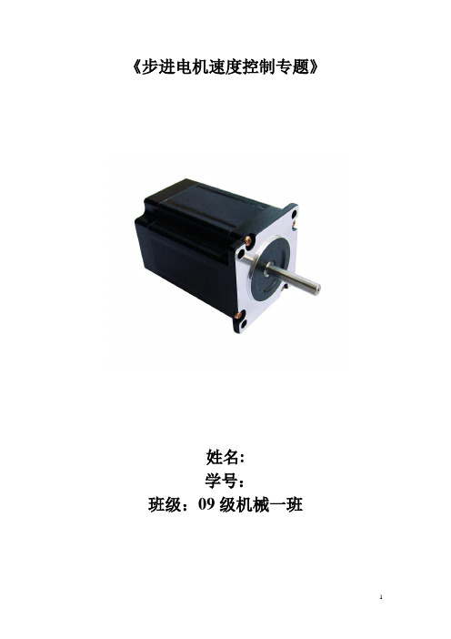
《步进电机速度控制专题》姓名:学号:班级:09级机械一班步进电机的速度控制步进电机区别于其他控制用途电机的最大特点是,它可接受数字控制信号(电脉冲信号)并转化成与之相对应的角位移或直线位移,因而本身就是一个完成数字模拟转化的执行元件。
而且它能进行开环位置控制,输入一个脉冲信号就得到一个规定的位置增量。
这样的增量位置控制系统与传统的直流伺服系统相比,其成本明显降低,几乎不必进行系统调整。
因此,步进电机广泛应用于数控机床、机器人、遥控、航天等领域,特别是微型计算机和微电子技术的发展,使步进电机获得更为广泛的应用。
步进电机的速度特性步进电机的转速取决于脉冲频率、转子齿数和拍数。
其角速度与脉冲频率成正比,而且在时间上与脉冲同步。
因而在转子齿数和运行拍数一定的情况下,只要控制脉冲频率即可获得所需速度。
由于步进电机是借助它的同步转矩而启动的,为了不发生失步,启动频率是不高的。
特别是随着功率的增加,转子直径增大,惯量增大,启动频率和最高运行频率可能相差10倍之多。
为了充分发挥电机的快速性能,通常使电机在低于启动频率下启动,然后逐步增加脉冲频率直到所希望的速度,所选择的变化速率要保证电机不发生失步,并尽量缩短启动加速时间。
为了保证电机的定位精度,在停止以前必须使电机从最高速度逐步减小脉冲率降到能够停止的速度(等于或稍大于启动速度)。
因此,步进电机拖动负载高速移动一定距离并精确定位时,一般来说都应包括“启动-加速-高速运行(匀速)-减速-停止”五个阶段,速度特性通常为梯形,如果移动的距离很短则为三角形速度特性示。
步进电机控制系统结构PC机在适当的时刻通过对硬件控制电路上的8253计数器0赋初值,设置好加减速过程的频率变化(即速度、加速度变化),以防止失步。
例如,在点位控制中设置好速度曲线图,在起动和升速时,使步进电机产生足够的转矩驱动负载,跟上规定的速度和加速度;在减速时,下降特性使负载不产生过冲,停止在规定的位置。

7042聚乙烯的参数7042聚乙烯是一种具有很高韧性和耐磨性的聚乙烯材料。
它是由乙烯单体聚合而成的,具有低密度和高分子量的特点。
7042聚乙烯在工业和日常生活中有广泛的应用,例如包装材料、管道、电线绝缘材料等。
本文将从物理性质、化学性质、应用领域等方面介绍7042聚乙烯的参数。
一、物理性质7042聚乙烯具有低密度、高韧性和耐磨性。
其密度约为0.92 g/cm³,相对分子质量约为70.2 kg/mol。
这种聚乙烯具有较高的柔软性和弹性,能够承受较大的拉伸力而不易破裂。
此外,7042聚乙烯还具有较好的耐磨性,能够在摩擦和磨损的条件下保持其完整性和性能。
二、化学性质7042聚乙烯是一种相对稳定的聚合物材料,具有较好的耐化学性。
它能够耐受一定浓度的酸、碱和有机溶剂的侵蚀,但在一些强氧化剂和强酸碱的作用下可能会出现降解或损坏。
此外,7042聚乙烯还对紫外线具有一定的抵抗能力,能够在一定程度下抵御紫外线的照射。
三、应用领域1. 包装材料:由于7042聚乙烯具有较好的柔软性和弹性,常被用于制作塑料袋、塑料薄膜等包装材料。
7042聚乙烯制成的包装材料具有较好的抗拉伸性和耐磨性,能够保护包装物品免受外界因素的损害。
2. 管道:7042聚乙烯制成的管道具有良好的耐腐蚀性和耐磨性,常被用于输送液体、气体或固体颗粒的管道系统。
这种管道材料不仅具有较长的使用寿命,而且还能够降低能源消耗和维护成本。
3. 电线绝缘材料:7042聚乙烯由于具有较好的电绝缘性能和耐热性能,常被用作电线绝缘材料。
它能够有效地阻隔电流的流动,同时还能够在一定温度范围内保持其性能稳定。
4. 其他应用:7042聚乙烯还常被用于制作塑料容器、塑料家具等日常用品。
由于其良好的耐磨性和韧性,7042聚乙烯制成的产品具有较长的使用寿命和较好的使用体验。
7042聚乙烯作为一种具有低密度、高韧性和耐磨性的材料,在包装材料、管道、电线绝缘材料等领域有广泛的应用。

iso 7042标准ISO 7042标准。
ISO 7042标准是指用于工业自动化系统和集成的术语和定义。
该标准的目的是为了提供一个统一的术语系统,以便在工业自动化领域中进行交流和理解。
ISO 7042标准的制定是为了解决不同国家、不同行业之间术语混乱、定义不清晰的问题,从而促进国际间的合作与交流。
ISO 7042标准的内容主要包括术语的定义和分类。
在工业自动化系统中,术语的准确性和一致性对于确保系统的顺利运行至关重要。
因此,ISO 7042标准对于术语的定义非常严谨,避免了歧义和误解的发生。
此外,ISO 7042标准还对术语进行了分类,将其按照不同的功能和特性进行了归类,便于工程师和技术人员在实际工作中进行使用和理解。
ISO 7042标准的重要性不言而喻。
在全球化的今天,不同国家、不同地区的企业和机构之间经常需要进行合作与交流。
而工业自动化系统作为生产和制造的重要基础设施,其术语和定义的一致性对于合作的顺利进行至关重要。
ISO 7042标准的出台,为全球范围内的工业自动化领域提供了统一的术语和定义,为合作与交流提供了坚实的基础。
ISO 7042标准的实施对于企业和机构来说也是一项重要的管理工作。
在实际的工程项目中,术语和定义的混乱往往会导致沟通不畅、工作效率低下甚至是工程质量的下降。
而遵循ISO 7042标准,使用统一的术语和定义,可以有效地避免这些问题的发生,提高工作效率,保证工程质量。
总之,ISO 7042标准的出台和实施对于工业自动化领域来说具有重要的意义。
它不仅为全球范围内的合作与交流提供了统一的基础,也为企业和机构提供了重要的管理工具。
因此,我们应该充分认识ISO 7042标准的重要性,遵循并严格执行这一标准,以推动工业自动化领域的健康发展。


704胶的抗拉强度704胶是一种常用的工业胶水,具有很高的抗拉强度。
在各种工业领域中,704胶都有着广泛的应用,例如汽车制造、船舶制造、飞机制造、建筑工程等等。
那么,这种胶水的抗拉强度到底有多强呢?下面就来详细介绍一下。
首先,我们需要了解什么是抗拉强度。
抗拉强度是指材料在受力时抵抗拉伸的能力,通常用来描述材料的强度。
在工业生产中,抗拉强度是一个非常重要的指标,因为它能够决定材料是否适合用于某种特定的工作环境。
那么,704胶的抗拉强度具体有多少呢?根据相关资料显示,704胶的抗拉强度可以达到100MPa以上。
这个数值相当于每平方毫米的受力能够承受100兆帕的压力,这是一个非常惊人的数字。
可以说,在各种工业领域中,704胶的抗拉强度都是非常优秀的。
那么,如何保证704胶的抗拉强度呢?其实,在生产过程中,704胶的抗拉强度是可以通过一系列措施来保证的。
首先,生产厂家需要选择优质的原材料,确保胶水本身的质量。
其次,在生产过程中需要控制各种参数,例如温度、湿度、压力等等,以确保产品的稳定性和一致性。
最后,在产品质量检验过程中,需要对704胶进行严格的测试和检验,以确保它的抗拉强度符合标准要求。
除了抗拉强度外,704胶还有很多其他的优点。
例如,它具有很好的耐化学性和耐热性,在各种恶劣环境下都能够保持稳定性。
此外,704胶还具有很好的粘接性能,可以牢固地粘合各种材料。
总之,704胶作为一种优秀的工业胶水,在各种工业领域中都有着广泛的应用。
其抗拉强度非常优秀,可以达到100MPa以上,这是一个非常惊人的数字。
在生产过程中,需要通过一系列措施来保证产品质量和稳定性。
相信在未来,704胶还会有更广泛的应用前景。
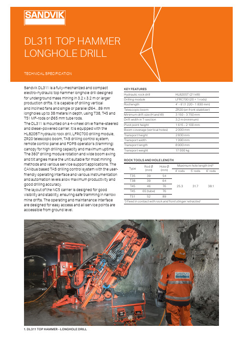
KEY FEATURES Hydraulic rock drill HL820ST (21 kW)Drilling module LFRC700 (20 + 1 rods)Rod length4’ - 6’ (1 220 - 1 830 mm)Telescopic boomZR20 (on front stabilizer)Minimum drift size (H and W) 3 150 - 3 750 mm Drift width in T-section 3.2 m (minimum)Pivot point height 1 615 - 2 100 mmBoom coverage (vertical holes)2 000 mm Transport height 2 830 mm Transport width1 990 mm Transport length8 900 mmTransport weight17 000 kg ROCK TOOLS AND HOLE LENGTHType Rod Ø (mm)Hole Ø (mm)Maximum hole length (m)*4’ rods5’ rods6’ rodsT35395425.331.738.1T383964T454676T4565 (tube)76T515289*) Feed in contact with rock and front stinger retractedSandvik DL311 is a fully-mechanized and compact electro-hydraulic top hammer longhole drill designed for underground mass mining in 3.2 x 3.2 m or larger production drifts. It is capable of drilling vertical and inclined fans and single or parallel Ø64…89 mm longholes up to 38 meters in depth, using T38, T45 and T51 MF-rods or Ø65 mm tube rods.The DL311 is mounted on a 4-wheel drive frame-steered and diesel-powered carrier. It is equipped with the HL820ST hydraulic rock drill, LFRC700 drilling module, ZR20 telescopic boom, TAS drilling control system, remote control panel and FOPS operator’s (tramming) canopy for high drilling capacity and maximum uptime. The 360° drilling module rotation and wide boom swing and tilt angles make the unit suitable for most mining methods and various service support applications. The CANbus based TAS drilling control system with the user-friendly operating interface and various instrumentation and automation levels allow maximum productivity and good drilling accuracy.The layout of the NC5 carrier is designed for goodvisibility and stability, ensuring safe tramming in narrow mine drifts. The operating and maintenance interface are designed for easy access and all service points areaccessible from ground level.DRILLING MODULE Type of drilling module LFRC700 (TS2-341)Rod length1 220 - 1 830 mm (4’ - 6’ )Storing capacity20 + 1 rods (all threads)Retaining centralizer Pito 7Cuttings diverter CC705Set-off from stope face 530 mm (minimum)Feed force31 kNFeed and return speed0.3 m/s (fast feed)Front stinger extension2 000 mmHYDRAULIC SYSTEM Type of hydraulic system TPC LHOperating principle Electric pilot control Power packHPP875 (75 kW)Filtration (pressure / return)20 µ / 10µOil tank volume 180 litersCooler for hydraulic oil OW45 oil-to-water (45 kW)Low oil level indicationLow oil level switchHYDRAULIC ROCK DRILL Type of rock drill HL820ST (TS2-301)Percussion power 21 kW Percussion pressureUp to 200 bar Percussion rate 42 - 52 Hz Stabilizer Sleeve typeRotation speed 0 - 180 rpm (OMT200)Rotation torque1 095 Nm (OMT200) Weight260 - 305 kg Length with shank adapter 1 241 mmOPERATOR’S SAFETY CANOPY FOPS safety canopy FOPS (ISO3449)Unit height in tramming 2 830 mmSound pressure level EN 791Canopy < 97 dB(A) Emitted 115 dB(A)Operator’s seatErgonomic T-back seatLONGHOLE BOOM Telescopic boom ZR20 (TS2-287)Boom swing Left 38° / right 38°Boom (fan) tiltBack 45° / Forward 30°Drilling module roll-over 360°Boom extension485 mmDrilling module travel985 mm (4' rods)1 050 mm (5’ rods)1 200 mm (6’ rods)Boom coverage (vertical holes) 2 000 mmPivot point height (boom vertical)1 615 - 2 100 mm Rear stingerMounted on feed cradle Rear stinger extension1 500 mmLaser distance from drill center 880 mm (vertical holes)ELECTRIC SYSTEM Standard voltages 380 - 690 V (50 or 60 Hz)Total installed power92 kW Main switch gear MSE / MSC IP-classification Specification TS2-132Allowed voltage fluctuation ± 10%Starting method Star-Delta (380 - 690 V)Automatic cable reel TCR1Cable reel remote control At operator station and cable reel Front and rear lights8 x 50 W (24 V) LED Pedestal lights2 x 50 W (24 V) LED Carrier positioning lights 2 x Laser type Sealed AGM batteries2 x 12 V (85 Ah)AIR AND WATER SYSTEM Flushing of holes By waterWater booster pump type WBP2 (4 kW / 50 Hz)Water pump capacity 100 l/min at 15 bar (inlet pressure = 4 bar)Water pump inlet pressure 2 - 7 bar Flushing water pressure 10 - 20 barAir compressorCTN10 (1.0 m³/min at 7 bar)Shank lubrication deviceSLU1 (air / oil mist)Rock drill air consumption 200 - 300 l/min Rock drill oil consumption 250 - 550 g/hAir cleaner for external air supplyIP5 including connectionDRILLING CONTROL SYSTEM Type of control system TASOperating principle CANbusControl panelPortable remote panel Cable length 20 m Adjustable parametersFull percussion CollaringRotation / Threading Feed / Anti-jamming Flushing Rotation pressure controlled feed With One-hole / Fan automation Diagnostics systemInteractiveDRILLING MODULE DIMENSIONS Type Rod length Total length LFRC704 1 220 mm 2 940 mm LFRC705 1 525 mm3 240 mm LFRC7061 830 mm 3 550 mmCARRIERType of carrierNC5 (frame-steered)Carrier articulation ± 40ºRear axle oscillation± 10ºGround clearance 320 mmDiesel engine Deutz TCD2012 (74 kW, Tier 3)Exhaust catalyzerStandard Transmission Hydrostatic Axles Spicer 112 and 123Tires12.00–20Service brakesHydraulically applied disc brakes Parking / emergency brakes SAHR fail safe type wet disc brakesTramming speedHorizontal (0%): 12 km/h 8°=1:7=14%: 5 km/h Gradeability / sideways tilt Max. 15° / 5°Carrier stabilization 2 x hydraulic outriggers (front) 2 x hydraulic jacks (rear)Fuel tank 80 liters Tramming oil tank55 liters Filling pump for hydraulic oil ElectricHand held fire extinguisher 7.7 or 9 kg (type ABC)Brake release By manual hand pump Tramming alarmStandardTrammin cameras Front, side and rear Knowledge Box™Connectivity solution (TS2-535)Colour schemeSandvikDocumentation1 x Operator’s manual 1 x Maintenance manual1 x Technical manual (in English only) 1 x Parts manual (in English only)2 x Toolman USB keyOPTIONAL ITEMSElectric system *Voltage optionDewatering pump outlet readinessElectric cablesGround fault and overcurrent unit Outlet on carrier 110 V Outlet on carrier 230 V Amber flashing light Battery jump start1 000 V (50 or 60 Hz) with DOL starterSite voltage 380 - 690 V (8 kW), excluding USA/CAN Specification TS2-121 VYK (excluding USA/CAN) 16 A, single phase, 1.6 kW 16 A, single phase, 2 kW LED (24 V) CATAir and water system *Air compressor Air mist flushing kit Compressed air outlet2 x 60 liters air receiversHooks and water hose Water hose reel and hoseCT28 (2.8 m³/min, 18.5 kW)For external air and water supply Quick coupling for pneumatic toolsFor end-of-hole flushing (requires CT28)Ø38 mm hose (lg: 30 m)THR and Ø38 mm hose (lg: 60 m)Fire suppression systemSpare hand held fire extinguisher Automatic fire suppression system Manual or automatic system 1 x 7.7 kg or 9 kg (type ABC Sandvik Eclipse™ Ansul (6 nozzles)Carrier*Foam filled tiresFast filling and evacuation system Wheel chocks and holders4 pcsWiggins (complete) 2 pcsExtra items Spare rock drillSpare wheel assembly Special tools for rock drill Warranty extension DocumentationPackage: Country specific options Package: Harsh waterPackage: Onboard air and water supplyHL820ST or HL710SStandard or foam filled tires Field kit or complete set One year (excl. Kazakhstan) Extra manualsLAM, CAN, USC, AUS, EUR Basic or Advanced (TS2-049) Specification TS2-328*) Replaces standard featureOPTIONAL ITEMSDrilling system *HL710S rock drill *Drilling module sideways swing Drilling module wear parts kit *Power extractor With 55 kW or 75 kW power pack ZR32P boom (TS2-289) For alternative tools For HL820ST and HL710S InstrumentationAccess detector or protector Drilling instrument TMS Spirit level angle indicators Teleremote drilling operation Proximity detectionMandatory in Europe (TS2-211) For DL300-series (TS2-122) 2 pcs (on feed and boom)Including data transfer (USB/WLAN) Interface to external system (TS2-381)AutomationRod handler sequence control One-hole automation Fan automationData transfer USB/WLAN (incl. DrillConnect mobile app)Specification TS2-197 Including TMS (TS2-198) Including TMS (TS2-199)Connectivity through Knowledge box™ for easy data transfer to and from the rigCleaning system Low pressure system with reel High pressure system with reelUp to 15 bar (TS2-343) Up to 220 bar (TS2-343)Greasing systems Automatic systemCarrier centralized greasing pointsManual systemLincoln (for carrier, boom and rod handler)Specification TS2-463Specification TS2-4631 8308 90015°15°3202 1452 51030°15°T S 2-243:09/E N G /M E T R I C © S a n d v i k M i n i n g a n d R o c k S o l u t i o n s 2022 S A N D V I K i s a r e g i s t e r e d t r a d e m a r k o w n e d b y S a n d v i k I n t e l l e c t u a l P r o p e r t y A B i n S w e d e n a n d o t h e r c o u n t r i e s .Sandvik Mining and Rock Solutions reserves the right to make changes to the information on this data sheet without prior notification to users. Please contact a Sandvik representative for clarification on specifications and options.ROCKTECHNOLOGY .SANDVIK。

VOLTAGE DETECTORFunction of this IC is accurately resetting the system afterdetecting voltage at the time of switching power on and instantaneous power off in various CPU systems and other logic systems.FEATURESCurrent Consumption is Low. I CCL =300A Typ. I CCH =30A Typ.Resetting Output Minimum Guarantee Voltage is Low 0.8V Typ.Hysteresis Voltage is Provided. 50mV Typ.Reset Signal Generation Starting Voltages :KIA7019 1.9V Typ. KIA7033 3.3V Typ.KIA7021 2.1V Typ. KIA7034 3.4V Typ. KIA7023 2.3V Typ. KIA7035 3.5V Typ. KIA7025 2.5V Typ. KIA7036 3.6V Typ.KIA7027 2.7V Typ. KIA7039 3.9V Typ.KIA7029 2.9V Typ. KIA7042 4.2V Typ.KIA7031 3.1V Typ. KIA7045 4.5V Typ.KIA7032 3.2V Typ. Taping Type is also Available.APPLICATIONS(1) As Control Circuit of Battery-Backed Memory.(2) As Measure Against Erroneous Operations at Power ON-OFF.(3) As Measure Against System Runaway at Instantaneous Break of Power Supply etc.(4) As Resetting Function for the CPU-Mounted Equipment, such as Personal Computers, Printers, VTRs and so forth.V CC OUTGNDEQUIVALENT CIRCUITELECTRICAL CHARACTERISTICS (V CC =5V, V EE =GND, Ta=25)MAXIMUM RATINGS (Ta=25)-0.3+15.0KIA7019AP 45AP400KIA7019AF 45AF KIA7019AT 45AT-30+75-55+150=200OL0.4V=200=15V A Vs =200mV Vs/T=2000.01%/IccL =Vsmin.-0.05V 300A IccH =5.25V A =200, V OL 0.4VV =1.0k , C =100pF s =1.0k, C =100pFs =Vsmin.-0.05V, Tc=25mA =Vsmin.-0.05V, Tc=-30+75mATEST CIRCUIT 1.CC V 5VV 5VV (NOTE)(1) Connecting of LED and R2 obtains a voltage drop indicator.(2) Connecting of C1 and selection of time constant with C1 and R1 set the power on delay time.PRECAUTION FOR USESOLDERINGFlat Package (SOT-89 Package)Elements mounting styles of electronic devices are gaining in further diversification over recent years, and needs for components are all the more expanding in varieties. Especially, surface mounting is steadily penetrating into industrialsegments as a world-wide popular technical trend. Although exposure to high temperature is inevitable during soldering we recommend limiting the soldering temperature to low levels as shown in figure for the sake of retaining inherentexcellent reliability.(a) When employing solder reflow methodAtmospheric temperature around resin surfaces must be less than 240, not exceeding the time length of 10 sec.Recommend temperature profile Precautions on heating methodWhen resin in kept exposed to high temperature for a long time, device reliability may be marred.Therefore, it is essential to complete soldering in the shortest time possible to prevent temperature of resin from rising.(b) When employing halogen lamps or infrared-ray heatersWhen halogen lamps or infrared-ray heaters are used, avoid direct irradiation onto resin surfaces; such devices cause extensive localized temperature rise.Please keep a reflow solder operating when SOT-89 package's soldering.。
The SLA7042M and SLA7044M are designed for high-efficiency and high-performance microstepping operation of 2-phase, unipolar stepper motors. Microstepping provides improved resolution without limiting step rates, and provides much smoother low-speed motor operation. An automated, innovative packaging technology combined with power NMOS FETs and monolithic CMOS logic/control circuitry advances power multi-chip modules (PMCMs™) toward the complete integration of motion control. Each half of these stepper motor control-ler/drivers operate independently. The 4-bit shift registers are serially loaded with motor phase information and output current-ratio data (eight levels). The combination of user-selectable current-sensing resistor,linearly adjustable reference voltage, and digitally selected outputcurrent ratio provides users with a broad, variable range of of full, half,and microstepping motor control (I OUT ≈ [V REF /3 • R S ] • Current Ratio).Each PMCM is rated for a maximum motor supply voltage of 46 V and utilizes advanced NMOS FETs for the high-current, high-voltage driver outputs. The avalanche-rated (≥100 V) FETs provide excellent ON resistance, improved body diodes, and very-fast switching. The multi-chip ratings and performance afford significant benefits andadvantages for stepper drives when compared to the higher dissipation and slower switching speeds associated with bipolar transistors. Highly automated manufacturing techniques provide low-cost and exception-ally reliable PMCMs suitable for controlling and directly driving a broad range of 2-phase, unipolar stepper motors. The SLA7042M and SLA7044M are identical except for r DS(on) and output current plete applications information is given on the following pages.PWM current is regulated by appropriately choosing current-sensing resistors, a voltage reference, and digitally programmable current ratio.Inputs are compatible with 5 V logic and microprocessors.BENEFITS AND FEATURESs Cost-Effective, Multi-Chip Solution s ‘Turn-Key’ Motion-Control Module s Motor Operation to 3 A and 46 V s 3rd Generation High-Voltage FETs s 100 V, Avalanche-Rated NMOS s Low r DS(on) NMOS Outputss Advanced, Improved Body Diodes s Microstepping Unipolar Drives High-Efficiency, High-Speed PWMAlways order by complete part number: SLA7042M .Data Sheet 28202A*s Independent PWM Current Control (2-Phase)s Digitally Programmable PWM Current Controls Low Component-Count PWM Drive s Low Internal-Power Dissipation s Electrically Isolated Power Tab s Logic IC- and µP-Compatible Inputss Machine-Insertable Package™MOTOR CONTROLLER/DRIVERS115 Northeast Cutoff, Box 15036Worcester, Massachusetts 01615-0036 (508) 853-5000™FUNCTIONAL BLOCK DIAGRAMNote that channels A and B are electrically isolated.25151050TEMPERATURE in °C20Dwg. GK-018-1A L L O W AB L E P AC K A G E P O W E RD I S S I P A T I O N i n W A T T SALLOWABLE PACKAGEPOWER DISSIPATIONDwg. FK-006CONTROL SUPPLYOUT OUT CHANNEL A PIN NUMBERS CHANNEL B PIN NUMBERSCopyright © 1995, 1998 Allegro MicroSystems, Inc.DC ELECTRICAL CHARACTERISTICS at T A = +25°C, V DD = 5 V unless otherwise noted.Limits Characteristic Symbol Test Conditions Min Typ Max UnitsFET Leakage Current IDSS VDS= 100 V—— 4.0mAFET ON Voltage VDS(ON)SLA7042M, IOUT= 1.2 A——800mVSLA7044M, IOUT= 3 A——855mVFET ON Resistance rDS(on)SLA7042M, IOUT= 1.2 A——0.67ΩSLA7044M, IOUT= 3 A——0.285ΩBody Diode Forward Voltage VSD SLA7042M, IOUT= –1.2 A—— 1.2VSLA7044M, IOUT= –3 A—— 1.6VControl Supply Voltage VDDOperating 4.5 5.0 5.5VControl Supply Current IDD Each controller, VDD= 5.5 V——7.0mALogic Input Voltage VIN(1)3.5——VVIN(0)—— 1.5VLogic Input Current IIN(1)VIN(1)= VDD—— 1.0µAIIN(0)VIN(0)= 0——–1.0µAREF/ENABLE Input Voltage VREF/ENDATA, CLOCK, STROBE, and OUT Enabled0.4— 2.5VDATA, CLOCK, STROBE, and OUT Disabled VDD- 1——V REF/ENABLE Input Current I REF/EN0 V ≤ V REF/EN≤ 5 V——±1.0µA Step Reference SRCR DATA Input = 000X—0—% Current Ratio DATA Input = 001X—20—%DATA Input = 010X—40—%DATA Input = 011X—55.5—% First Bit Entered (X) = Phase DATA Input = 100X—71.4—% Second Bit Entered = LSB DATA Input = 101X—83—% Last Bit Entered = MSB DATA Input = 110X—91—%DATA Input = 111X—100—% NOTE: Negative current is defined as coming out of (sourcing) the specified device pin.TYPICAL AC CHARACTERISTICS at T A = +25°C, V DD = 5 V, I OUT = 1 A, Logic Levels are V DD and GroundPWM OFF Time DATA Input = 001X.................................................................7 µsDATA Input = 010X.................................................................7 µsDATA Input = 011X.................................................................9 µsDATA Input = 100X.................................................................9 µsDATA Input = 101X.................................................................9 µsDATA Input = 110X................................................................11 µsDATA Input = 101X................................................................11 µs Output RiseTime t r10% to 90%...........................................................................0.5 µsOutput Fall Time t f90% to 10%...........................................................................0.1 µsStrobe-to-Output Switching Time t pd50% to 50%...........................................................................0.7 µs MOTOR CONTROLLER/DRIVERSMOTOR CONTROLLER/DRIVERS115 Northeast Cutoff, Box 15036Worcester, Massachusetts 01615-0036 (508) 853-5000™Dwg. WK-002SERIAL PORT TIMING CONDITIONS(T A = +25°C, Logic Levels are V DD and Ground)A. Minimum Data Active Time Before Clock Falling Edge (Data Set-Up Time)........... 150 nsB. Minimum Data Active Time After Clock Falling Edge (Data Hold Time).................. 150 nsC. Minimum Data Pulse Width...................................................................................... 350 nsD. Minimum Clock Pulse Width .................................................................................... 350 nsE. Minimum Time Between Clock and Strobe Falling Edges ....................................... 650 nsF. Minimum Strobe Pulse Width...................................................................................500 nsAPPLICATIONS INFORMATIONThe SLA7042M and SLA7044M modules integrate two CMOS controller ICs and four NMOS FETs. Each half of the device operates independently, although the CLOCK inputs may be connected together and the STROBE inputs may be connected together. Pulling V REF/EN low (<2.5 V) allows the 4-bit shift registers to be serially loaded with motor phase and output currrent ratioing data.The first bit selects the motor phase (logic high = Output A or B, logic low = Output A or B); the next three bits determine the motor current ratio (eight steps, 0% to 100%). The internal D/A converter, in conjunction with a current-sensing resistor and input reference voltage, completes the microstepping current control.Pulling V REF/EN high (within 1 V of V DD ) resets the shift register and latches to turn the MOS drivers OFF and inhibits the serial DATA input.FIGURE 2.␣ PWM CONTROL (RUN MODE)V V SERIAL DATASERIAL DATA INPUT ENABLEIn a minimum-component application, a voltage divider provides V REF/EN and an npn transistor provides the required pull-down to enable the serial data input as shown in Figure 2.I OUT max ≈R 2•V b R 1 + R 23 •R SµP STEPPER MOTOR CONTROLAlternative REFERENCE/ENABLE input configura-tions provide for more complete motor control. A tri-state logic element and a voltage divider allows a fixed refer-ence voltage, with both output disable and data enable functions. Complete µP control is usually accomplished with a D/A converter as shown in Figure 3. Here, digital control provides an output disable (>V DD - 1 V), V REF , and V EN (<2.5 V).MOTOR CONTROLLER/DRIVERSDwg. WK-001PHASE APHASE AIOUTREGULATING THE PWM OUTPUT CURRENTThe output current (and motor coil current) waveform is illustrated in Figure 1. Setting the maximum PWM current trip point to meet the specified full-step running current for the motor, I OUT max (DATA input = 111X =100% ratio), requires only a current-sensing resistor, R S ,and an input reference voltage, V REF/EN , between 0.4 V and 2.5 V.I OUT max ≈V REF/EN 3 •R SFIGURE 1.␣ PHASE A COIL CURRENT WAVEFORMMOTOR CONTROLLER/DRIVERS115 Northeast Cutoff, Box 15036Worcester, Massachusetts 01615-0036 (508) 853-5000™V V FIGURE 3. ␣C OMPLETE CONTROLSERIAL DATA INPUTThe serial DATA input port is enabled (active low) by the REFERENCE/ENABLE input. When V REF/EN is be-tween 0.4 V and 2.5 V, information on the DATA input is read into the shift register on each high-to-low transition of the CLOCK.There are four bits: the first bit entered controls theFIGURE 4. ␣T IMING RELATIONSHIPSmotor phase — a high level enables OUT A or OUT B , a low level enables OUT A or OUT B . The next three bits set the step reference voltage ratio and PWM OFF time as shown in the Characteristics Tables — the least-significant bit first and the most-significant bit last.Data written into the serial data port is latched and becomes active on a high-to-low transition at STROBE.Dwg. WK-003REFERENCE/ENABLE INPUTThe serial DATA input port is enabled (active low) by the REFERENCE/ENABLE input when V REF/EN is between 0.4 V and 2.5 V. With V REF/EN greater than V DD - 1 V, the serial DATA input port is disabled, the outputs are OFF,and the controller/driver will not be affected by changes at the DATA, CLOCK, or STROBE inputs.With V REF/EN between 0.4 V and 2.5 V, the output current limit is a linear function of V REF and the step reference current ratio.I OUT ≈ V REF•SRCR3 •R S In a typical (SLA7042M) application where V DD = 5 V,a V REF/EN between 0.4 V and 2.5 V, and a maximumallowable load current of 1.2 A, the maximum value of R S is 0.69 Ω and I OUT min is 0.11 A when SRCR is 100%(DATA input = 111X).POWER DISSIPATION CALCULATIONSThe SLA7042/44M normally do not require special heat sinking except under unusual circumstances (two phases operating near maximum output current and T A >65°C). However, as with all power drivers, the basic constituents of power dissipation should be evaluated.Conduction losses (internal power dissipation) include:(a)FET output power dissipation (I OUT 2 • r DS(on) or I OUT • V DS(ON)),(b)FET body diode power dissipation (V SD • I OUT ), and (c)control circuit power dissipation (V DD • I DD ).PACKAGE RATINGS/DERATING FACTORSThermal calculations must also consider the tempera-ture effects on the output FET ON resistance. The appli-cable thermal ratings for the 18-lead power-tab SIP PMCM package are:R θJA = 28°C/W (junction to ambient with no heat sink)or 4.5 W at +25°C and a derating factor of -36 mW/°C for operation above +25°C.R θJM = 5°C/W (junction to mounting surface).TEMPERATURE EFFECTS ON FET r DS(on)Analyzing safe, reliable operation includes a concern for the relationship of NMOS ON resistance to junction temperature. Device package power calculations must include the increase in ON resistance (producing higher output ON voltages) caused by higher operating junction temperatures. Figure 5 provides a normalized ON resis-tance curve, and all thermal calculations should consider increases from the given +25°C limits, which may be caused by internal heating during normal operation.FIGURE 5.␣ NORMALIZED ON RESISTANCEvs TEMPERATURE 2.01.0-40+80+1600.5JUNCTION TEMPERATURE in °CN O R M A L I Z E D F E T O N R E S I S T A N C EDwg. GK-0171.52.5+40+120The power MOSFET outputs of these devices are similar to the International Rectifier type IRL510(SLA7042M) and IRL520 (SLA7044M). These devices feature an excellent combination of fast switching, rugged-ized device design, low on-resistance, and cost effective-ness.SLA7042M AND SLA7044M MICROSTEPPING,UNIPOLAR PWM, HIGH-CURRENT MOTOR CONTROLLER/DRIVERSSLA7042M AND SLA7044M MICROSTEPPING,UNIPOLAR PWM, HIGH-CURRENTMOTOR CONTROLLER/DRIVERS115 Northeast Cutoff, Box 15036Worcester, Massachusetts 01615-0036 (508) 853-5000™±NOTES: 1. Exact body and lead configuration at vendor’s option within limits shown.2. Recommended mounting hardware torque: 4.34 – 5.79 lbf•ft (6 – 8kgf•cm or 0.588 – 0.784 Nm).3. The shaded area is exposed (electrically isolated) heat spreader.4. Recommend use of metal-oxide-filled, alkyl-degenerated oil base,silicone grease (Dow Corning 340 or equivalent).±Dimensions in Inches (for reference only)Dimensions in Millimeters (controlling dimensions)The products described here are manufactured in Japan by Sanken Electric Co.,Ltd. for sale by Allegro MicroSystems, Inc.Sanken Electric Co., Ltd. and Allegro MicroSystems, Inc. reserve the right to make, from time to time, such departures from the detail specifications as may be required to permit improvements in the design of their products.The information included herein is believed to be accurate and reliable.However, Sanken Electric Co., Ltd. and Allegro MicroSystems, Inc. assume no responsibility for its use; nor for any infringements of patents or other rights of third parties which may result from its use.This datasheet has been download from: Datasheets for electronics components.。